BEI Electronics 7EPTX-STX60 60W LPFM Broadcast Transmitter User Manual Exhibit D Users Manual per 2 1033 c3
BEI Electronics, LLC 60W LPFM Broadcast Transmitter Exhibit D Users Manual per 2 1033 c3
UserManual.wiki
>
BEI Electronics
>
7EPTX STX60 User Manual
Exhibit D Users Manual per 2 1033 c3
Navigation menu
Upload a User Manual
Namespaces
Wiki Guide
HTML
PDF
Info
Views
User Manual
Discussion / Help
Navigation


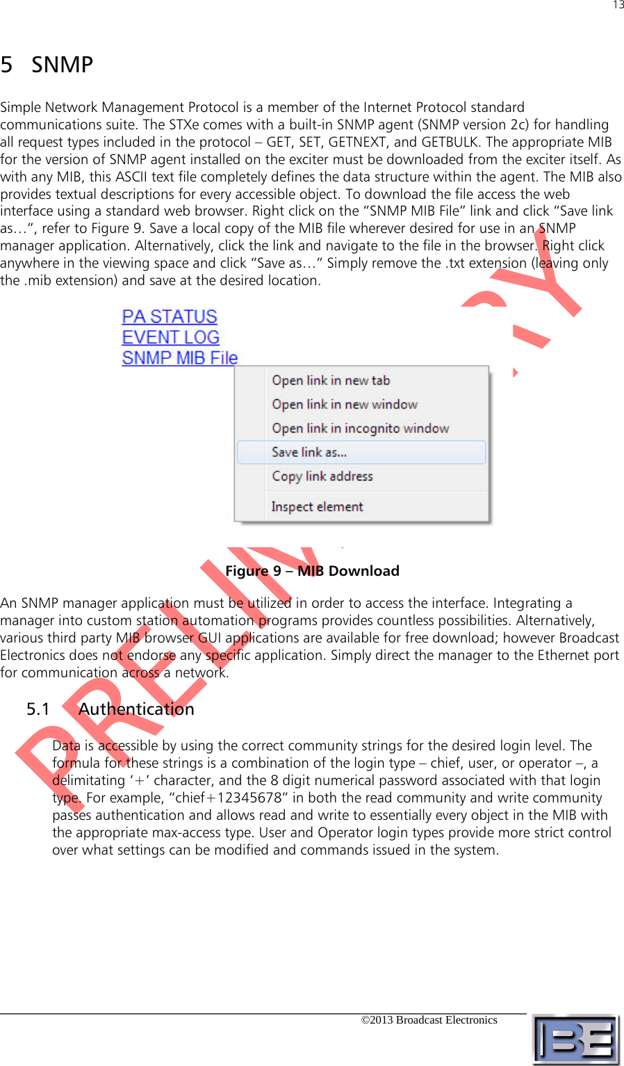
![12 ©2013 Broadcast Electronics Figure 7 – Web Interface PA Page Figure 8 – Web Interface Events Page To check the current web page version, simply point a web browser to [IP Address]/rev.html](https://usermanual.wiki/BEI-Electronics/7EPTX-STX60/User-Guide-2051660-Page-24.png)