BEI Electronics 7EPTX-STX60 60W LPFM Broadcast Transmitter User Manual Exhibit D Users Manual per 2 1033 c3
BEI Electronics, LLC 60W LPFM Broadcast Transmitter Exhibit D Users Manual per 2 1033 c3
Exhibit D Users Manual per 2 1033 c3
Broadcast Electronics
4100 North 24th Street, Quincy, Illinois 62305 USA • Phone (217) 224-9600 • Fax (217) 224-9607 • www.bdcast.com • bdcast@bdcast.com
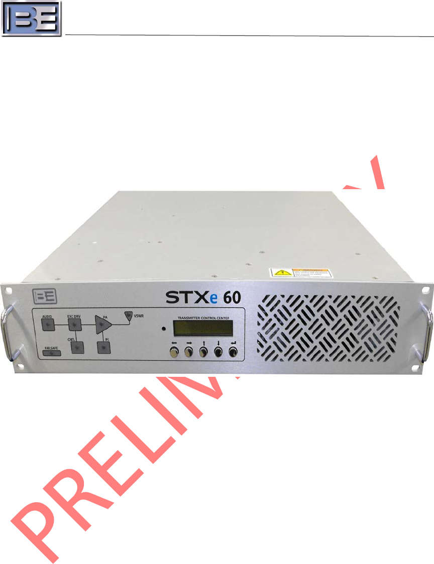
STXe – 60 Watt FM Exciter
Operation Manual
597-4062
Revision A
July 23, 2013

STXe – 60 Watt FM Exciter
Operation Manual
©2013 Broadcast Electronics all rights reserved.
The information in this publication is subject to improvement and change without notice. Although
every effort is made to ensure the accuracy of the information in this manual, Broadcast Electronics
accepts no responsibility for any errors or omissions. Broadcast Electronics reserves the right to
modify and improve the design and specifications of the equipment in this manual without notice.
Any modifications shall not adversely affect performance of the equipment so modified.
Proprietary Notice
This document contains proprietary data of Broadcast Electronics. No part of this publication may be
reproduced, transmitted, transcribed, stored in a retrieval system, translated into any other language
in any form or by any means, electronic or mechanical, including photocopying or recording, for any
purpose, without the express written permission of Broadcast Electronics.
Trademarks
Broadcast Electronics and the BE logo are registered trademarks of Broadcast Electronics.
Marti Electronics and the Marti logo are registered trademarks of Broadcast Electronics.
All other trademarks are property of their respective owners.
Copyright
Copyright laws protect artwork depicting circuitry in this manual.
Information in this manual is subject to change without notice and does not represent a
commitment on the part of Broadcast Electronics.
Broadcast Electronics may make improvements and/or changes in this manual or in the product
described herein at any time.
This product could include technical inaccuracies or typographical errors.

i
©2013 Broadcast Electronics
Broadcast Electronics Product Warranty (Two-Year Limited)
BE hereby warrants all new products manufactured by BE against any defects in material or
workmanship at the time of delivery thereof, or that develop under normal use within a period of
two (2) years from the date of shipment.
BE reserves the right to repair equipment under warranty with new or refurbished equipment or
parts. BE’s sole responsibility with respect to any equipment or parts not conforming to this warranty
is to replace or repair such equipment upon the return thereof F.O.B. to BE’s factory in Quincy,
Illinois, U.S.A. In the event of replacement pursuant to the foregoing warranty, only the unexpired
portion of the warranty from the time of the original purchase will remain in effect for any such
replacement.
This warranty shall exclude the following products, component parts and/or assemblies:
(a) Transmitter power output tubes shall only carry the original manufacturers’ or
suppliers’ standard warranty in effect on their original shipment date.
(b) All computers, computer peripherals, cables, hard disk drives, etc., shall only carry
the manufacturers’ or suppliers’ standard warranty in effect on their original
shipment date.
(c) “Components”, defined as separate and individual parts (e.g. transistors, integrated
circuits, capacitors, resistors, inductors, fans, etc), resold by BE from another
manufacturer or supplier, shall only carry a 90 day warranty, effective the date of
shipment. Any such ‘Components’ being returned for warranty claim must be (1)
returned in their original packaging and (2) must be in new, unused condition. BE is
unable to process or resolve component defects or performance concerns on
components that have been soldered, installed, wired or in any way altered from
new their new condition.
(d) “Resale Equipment”, defined as equipment purchased from another manufacturer
or supplier, then resold by BE, shall only carry such manufacturer’s or supplier’s
standard warranty in effect as of the original shipment date. All warranty claims
against any and all ‘resale equipment’ sold by BE must be filed directly with the
original equipment manufacturer. BE is unable to process or resolve equipment
defects or performance concerns on products or services not manufactured by BE.
This warranty shall not extend to claims resulting from any acts of God, terrorism, war, defects or
failures caused by Purchaser or user abuse or misuse, operator error, or unauthorized attempts to
repair or alter the equipment in any way.
Under no circumstances shall BE be responsible for indirect, incidental or consequential damages,
including, but not limited to transportation costs, non-authorized repair or service costs, downtime
costs, costs for substituting equipment or loss of anticipated profits or revenue, incurred by
Purchaser, whether based in contract, tort or for negligence or breach of statutory duty or otherwise.
The terms of the foregoing warranty shall be null and void if the equipment has been altered or
repaired without specific written authorization from BE, or if not installed according to BE’s
instruction manuals, including, but not limited to, the absence of proper grounding, surge (TVSS)
protection on the AC circuit panel or proper lightning protection/grounding on all output circuits, or
if equipment is operated under environmental conditions or circumstances other than those
specifically described in BE’s product literature or instruction manual which accompany the
equipment.
The warranty shall be voided if the product or subassembly is equipped with a tamper
seal and that tamper seal is broken.
BE shall not be liable for any expense of any nature whatsoever
incurred by the original user without prior written consent of BE. The warranty provided herein shall
terminate at the end of the period set forth above.
This warranty extends only to the original
Purchaser and is not transferable.
There are no third party beneficiaries of any of the provisions of

ii
©2013 Broadcast Electronics
this warranty. If the equipment is described as “used” equipment, it is sold as is and where is and no
warranty applies unless authorized in writing. .
EXCEPT AS SET FORTH HEREIN, AS TO TITLE AND AS SPECIFICALLY REQUIRED BY LAW, THERE ARE
NO OTHER WARRANTIES, OR ANY AFFIRMATIONS OF FACT OR PROMISES BY BE, WITH REFERENCE
TO THE EQUIPMENT, OR TO MERCHANTABILITY, FITNESS FOR A PARTICULAR APPLICATION, SIGNAL
COVERAGE, INFRINGEMENT, OR OTHERWISE, WHICH EXTEND BEYOND THE DESCRIPTION OF THE
EQUIPMENT ON THE FACE HEREOF.

iii
©2013 Broadcast Electronics
IMPORTANT INFORMATION
EQUIPMENT LOST OR DAMAGED IN TRANSIT
When delivering the equipment to you, the truck driver or carriers’ agent will present a receipt for
your signature. Do not sign it until you have:
1) Inspected the containers for visible signs of damage and 2) Counted the containers and compared
with the amount shown on the shipping papers. If a shortage or evidence of damage is noted, insist
that notation to that effect be made on the shipping papers before you sign them.
Further, after receiving the equipment, unpack it and inspect thoroughly for concealed damage. If
concealed damage is discovered, immediately notify the carrier, confirming the notification in
writing, and secure an inspection report. This item should be unpacked and inspected for damage
WITHIN 15 DAYS after receipt. Claims for loss or damage will not be honored without proper
notification of inspection by the carrier.
RF PRODUCT TECHNICAL ASSISTANCE, REPAIR SERVICE, PARTS -
Technical assistance is available from Broadcast Electronics by letter, prepaid telephone or E-mail.
Equipment requiring repair or overhaul should be sent by common carrier, prepaid, insured, and well
protected. If proper shipping materials are not available, contact the RF Technical Services
Department for a shipping container. Do not mail the equipment. We can assume no liability for
inbound damage, and necessary repairs become the obligation of the shipper. Prior arrangement is
necessary. Contact the RF Technical Services Department for a Return Authorization.
Emergency and warranty replacement parts may be ordered from the following address. Be sure to
include the equipment model number, serial number, part description, and part number. Non-
emergency replacement parts may be ordered directly from the Broadcast Electronics stock room at
the number shown below.
RF TECHNICAL SERVICES
Telephone: +1 (217) 224-9617
E-Mail: rfservice@bdcast.com
Fax: +1 (217) 224-6258
FACILITY CONTACTS
Broadcast Electronics, - Quincy Facility
4100 N. 24th St. P.O. BOX 3606
Quincy, Illinois 62305
Telephone: +1 (217) 224-9600
Fax: +1 (217) 224-6258
General E-Mail: bdcast@bdcast.com
Web Site: www.bdcast.com
PARTS
Telephone: +1 (217) 224-9617
E-Mail: parts@bdcast.com

iv
©2013 Broadcast Electronics
RETURN, REPAIR, AND EXCHANGES
Do not return any merchandise without our written approval and Return Authorization. We will
provide special shipping instructions and a code number that will assure proper handling and
prompt issuance of credit. Please furnish complete details as to circumstances and reasons when
requesting return of merchandise. All returned merchandise must be sent freight prepaid and
properly insured by the customer.
MODIFICATIONS
Broadcast Electronics, reserves the right to modify the design and specifications of the equipment in
this manual without notice. Any modifications shall not adversely affect performance of the
equipment so modified.

v
©2013 Broadcast Electronics
SAFETY PRECAUTIONS
PLEASE READ AND OBSERVE ALL SAFETY PRECAUTIONS
ALL PERSONS WHO WORK WITH OR ARE EXPOSED TO POWER TUBES, POWER
TRANSISTORS, OR EQUIPMENT WHICH UTILIZES SUCH DEVICES MUST TAKE PRECAUTIONS
TO PROTECT THEMSELVES AGAINST POSSIBLE SERIOUS BODILY INJURY. EXERCISE EXTREME
CARE AROUND SUCH PRODUCTS. UNINFORMED OR CARELESS OPERATION OF THESE
DEVICES CAN RESULT IN POOR PERFORMANCE, DAMAGE TO THE DEVICE OR PROPERTY,
SERIOUS BODILY INJURY, AND POSSIBLY DEATH.
DANGEROUS HAZARDS EXIST IN THE OPERATION OF POWER TUBES AND
POWER TRANSISTORS
The operation of power tubes and power transistors involves one or more of the following hazards,
any one of which, in the absence of safe operating practices and precautions, could result in serious
harm to personnel.
A. HIGH VOLTAGE - Normal operating voltages can be deadly. Additional information
follows.
B. RF RADIATION - Exposure to RF radiation may cause serious bodily injury possibly
resulting in Blindness or death. Cardiac pacemakers may be affected. Additional
information follows.
C. HOT SURFACES - Surfaces of air-cooled radiators and other parts of tubes can reach
temperatures of several hundred degrees centigrade and cause serious burns if touched.
Additional information follows.
D. RF BURNS - Circuit boards with RF power transistors contain high RF potentials. Do
not operate an RF power module with the cover removed.

vi
©2013 Broadcast Electronics
HIGH VOLTAGE
Many power circuits operate at voltages high enough to kill through electrocution. Personnel should
always break the primary AC Power when accessing the inside of the transmitter.
RADIO FREQUENCY RADIATION
Exposure of personnel to RF radiation should be minimized, personnel should not be permitted in the
vicinity of open energized RF generating circuits, or RF transmission systems (waveguides, cables,
connectors, etc.), or energized antennas. It is generally accepted that exposure to “high levels” of
radiation can result in severe bodily injury including blindness. Cardiac pacemakers may be affected.
The effect of prolonged exposure to “low level” RF radiation continues to be a subject of
investigation and controversy. It is generally agreed that prolonged exposure of personnel to RF
radiation should be limited to an absolute minimum. It is also generally agreed that exposure should
be reduced in working areas where personnel heat load is above normal. A 10 mW/cm2 per one
tenth hour average level has been adopted by several U.S. Government agencies including the
Occupational Safety and Health Administration (OSHA) as the standard protection guide for
employee work environments. An even stricter standard is recommended by the American National
Standards Institute which recommends a 1.0 mW/cm2 per one tenth hour average level exposure
between 30 Hz and 300 MHz as the standard employee protection guide (ANSI C95.1-1982).
RF energy must be contained properly by shielding and transmission lines. All input and output RF
connections, such as cables, flanges and gaskets must be RF leak proof. Never operate a power tube
without a properly matched RF energy absorbing load attached. Never look into or expose any part
of the body to an antenna or open RF generating tube or circuit or RF transmission system while
energized. Monitor the tube and RF system for RF radiation leakage at regular intervals and after
servicing.
HOT SURFACES
The power components in the transmitter are cooled by forced-air and natural convection. When
handling any components of the transmitter after it has been in operation, caution must always be
taken to ensure that the component is cool enough to handle without injury.

vii
©2013 Broadcast Electronics
Table of Contents
1 Overview.............................................................................................................................. 1
2 Front Panel Features ............................................................................................................ 2
2.1 FAILSAFE ............................................................................................................................. 2
2.2 AUDIO ................................................................................................................................. 2
2.3 EXC DRV .............................................................................................................................. 2
2.4 CNTL.................................................................................................................................... 3
2.5 PA ....................................................................................................................................... 3
2.6 PS ........................................................................................................................................ 3
2.7 VSWR .................................................................................................................................. 3
2.8 TRANSMITTER CONTROL CENTER ......................................................................................... 3
3 Transmitter Control Center ................................................................................................. 4
3.1 Contrast Control .................................................................................................................. 4
3.2
Left Button ...................................................................................................................... 4
3.3
Right Button .................................................................................................................... 4
3.4
Up Button ........................................................................................................................ 4
3.5
Down Button .................................................................................................................... 5
3.6
Return Button ................................................................................................................. 5
4 Web Page .......................................................................................................................... 11
5 SNMP ................................................................................................................................. 13
5.1 Authentication................................................................................................................... 13
5.2 Objects .............................................................................................................................. 14
6 Backup Control Modes ...................................................................................................... 18
6.1 Emergency Control Mode .................................................................................................. 18
6.2 Standby System Control and Exciter ................................................................................... 18
7 Troubleshooting ................................................................................................................ 19
7.1 Event Log .......................................................................................................................... 19
7.2 Standby ............................................................................................................................. 19
7.3 Failsafe .............................................................................................................................. 19
7.4 Mute ................................................................................................................................. 20
7.5 Internal Exciter Diagnostics ................................................................................................ 20
7.6 Power Amplifier Diagnostics .............................................................................................. 20

viii
©2013 Broadcast Electronics
Figures
Figure 1 – Main Assembly Front Panel ........................................................................................... 2
Figure 2 – Transmitter Control Center ........................................................................................... 4
Figure 3 – Transmitter Control Center Menus Sheet 1 ................................................................... 7
Figure 4 – Transmitter Control Center Manus Sheet 2 ................................................................... 9
Figure 5 – Web Interface Main Page ........................................................................................... 11
Figure 6 – Web Interface Authentication ..................................................................................... 11
Figure 7 – Web Interface PA Page ............................................................................................... 12
Figure 8 – Web Interface Events Page ......................................................................................... 12
Figure 9 – MIB Download ........................................................................................................... 13
Figure 10 – STXe60 System Block Diagram .................................................................................. 23
Tables
Table 1 – SNMP Object Access .................................................................................................... 14
Table 2 – Exciter Diagnostics Details ............................................................................................ 20
Table 3 – PA Diagnostics Details .................................................................................................. 20

1
©2013 Broadcast Electronics
Overview 1
The STXe FM exciter series is designed to provide a cost effective solution for FM broadcast.
Every STXe exciter is tested at the factory for quality and reliability. Technicians will use settings given
to sales representatives at the time of purchase. In the absence of this information, the following
default settings are used:
• Frequency – 98.5 MHz
• Operating Mode – FM Only
• Total Output Power – Set to model name (1 kW Model - 1000 W, etc.)
• Emergency Output Power – 0 W
• 100% Modulation – 75 kHz
• Pre-emphasis – 75 µs
• Pilot Injection – On, 10%
• Mono/Stereo Mode - Stereo
• Audio Input – AES
• AES Injection Level – 100% at -2dBfs
• Analog L/R Injection Level – 100% with 3.5 Vpp at 400 Hz
• SCA1 Injection – Off, 10% with 3.5 Vpp at 67 kHz
• SCA2 Injection – Off, 10% with 3.5 Vpp at 92 kHz
• RDS Injection – Off, 10% with 3.5 Vpp at 53 kHz
• Real Time Clock – Central Standard Time. Note: The internal real time clock will stop
keeping time and reset to 2000-01-01 00:00:00 when the system has no AC power for
a few days. This is highly likely when the exciter is shipped.
• Ethernet
o DHCP - Disabled
o I.P. – 10.2.4.110
o Subnet Mask – 255.255.0.0
o Gateway – 10.2.1.1
• Passwords
o Chief – 12345678
o User – 22222222
o Operator – 11111111
For installation instruction, please see the STXe FM Exciter Installation and Maintenance Application
Guide. A copy can be found in the front of the binder containing this manual that is shipped with all
STXe exciters. For electronic copies of any technical documentation please visit
http://www.bdcast.com/information-center/ and follow navigation on the left side of the page –
authorized login is required for download of technical documents.
2
©2013 Broadcast Electronics
Front Panel Features 2
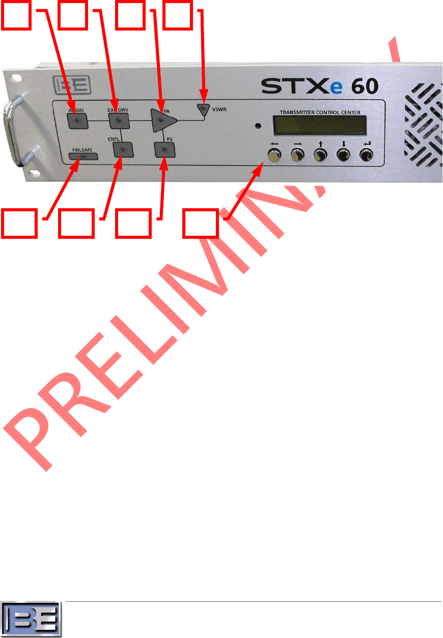
The main assembly front panel contains LED indicators for the system controller, internal
exciter, internal power amplifier, and an LCD user interface.
Figure 1 – Main Assembly Front Panel
2.1 FAILSAFE
The failsafe LED is coupled directly to the failsafe input on the back panel. Green indicates
the failsafe is connected for normal operation. If red the failsafe is not connected and RF
power will not turn on.
2.2 AUDIO
The audio LED indicates the status of the current primary audio source. If an audio peak
silence condition is detected, this LED turns red. The LED remains green until a failure is
detected. Check the exciter diagnostics for details on what alarms or faults may be active.
2.3 EXC DRV
The exciter drive LED indicates the status of any alarms or faults related to the exciter. Green
indicates that the exciter has settled into normal operating conditions. Orange indicates an
alarm condition. Red shows when the exciter has a fault condition. See Table 2 – Exciter
Diagnostics Details in section 7.5 for more information.
Note that there is overlap between internal exciter and internal PA status for drive detection.
An exciter drive alarm indication may originate from the PA. The exciter must also establish
frequency lock as it powers up. These are intended to indicate conditions that prevent full
operation whether the conditions are expected or not. Check the exciter and PA diagnostics
for details on what alarms or faults may be active.
2
3
5
7
6
4
1
8

3
©2013 Broadcast Electronics
2.4 CNTL
The system control LED shows the status of the system controller. Green indicates normal
control operation. Red indicates a loss of communication between the front panel and the
system controller.
2.5 PA
The power amplifier LED shows status of the internal PA. Green indicates normal power
control. Orange indicates an alarm condition. Red indicates a fault and PA shutdown
condition. Check PA diagnostics for details on what alarms or faults may be active.
2.6 PS
The power supply LED shows the status of the RF power supply module. Green indicates
normal operation. Orange indicates a self-reported alarm. Red indicates a determined fault.
Check PA diagnostics for details on what alarms or faults may be active in the supply
connected to the PA.
Note that these power supplies are on the same communications node as the PA they are
connected to. A communication fault will illuminate red on both the PA and the PS LEDs.
2.7 VSWR
The voltage standing wave ratio LED shows the status of the internal PA output in terms of
measured reflected power. Green indicates normal operation into an acceptable load.
Orange indicates active foldback protection. Red indicates a fault and shutdown condition.
Check PA diagnostics for details on what alarms or faults may be active in the PA.
2.8 TRANSMITTER CONTROL CENTER
This front panel LCD interface can be used for control and monitoring of all features in the
system. Use the five buttons below the screen to navigate and make modifications. See
section 3 - Transmitter Control Center for details on how to use this interface.

4
©2013 Broadcast Electronics
Transmitter Control Center 3
Initial system setup after installation requires interfacing with the LCD display and buttons on the
front of the main assembly. Once initial setup is complete, almost all configurations accessible on this
control center can be modified remotely via Ethernet interfaces.
Figure 2 – Transmitter Control Center
3.1 Contrast Control
A potentiometer tuning tool can be used to adjust the contrast on the LCD screen if desired.
Turning the potentiometer clockwise reduces contrast, and turning it counter-clockwise
increases contrast.
3.2
Left Button
The context dependent left button performs two primary functions. When navigating
between screens it allows a return to the main screen from any other navigation screen.
When an editing screen is entered this button moves the cursor one space to the left.
3.3
Right Button
The context dependent right button performs two primary functions. When navigating
between screens it allows a return to the first screen of the submenu tree. When an editing
screen is entered this button moves the cursor one space to the right.
3.4
Up Button
The context dependent up button performs various functions. When navigating between
screens through the trunk it selects a new submenu tree. After entering a submenu screen it
either selects different branches or cycles through options. When an editing screen is
entered this button modifies the object located at the cursor.
1
2
3
4
5
6

5
©2013 Broadcast Electronics
3.5
Down Button
The context dependent down button performs various functions. When navigating between
screens through the trunk it selects a new submenu tree (in the opposite direction as the up
button). After entering a submenu screen it either selects different branches or cycles
through options. When an editing screen is entered this button modifies the object located
at the cursor.
3.6
Return Button
The context dependent down button performs two primary functions. When navigating
between screens through the trunk it enters the next level in the menu. This can lead to
submenu screens, options selection, or field editing. Once an editing function has been
made this saves the field and returns to the first screen in the submenu tree.

6
©2013 Broadcast Electronics
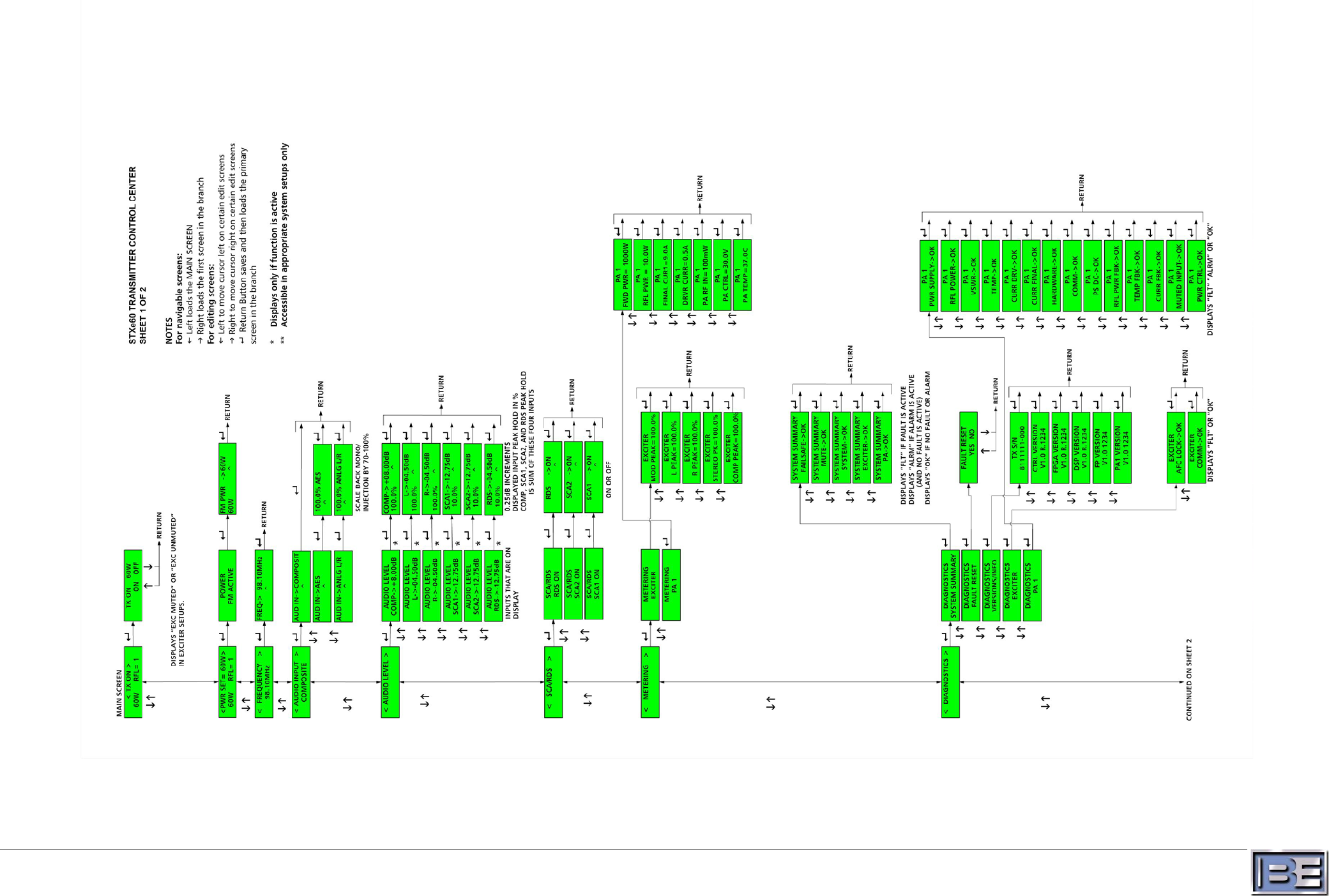
7
©2013 Broadcast Electronics
Figure 3 – Transmitter Control Center Menus Sheet 1
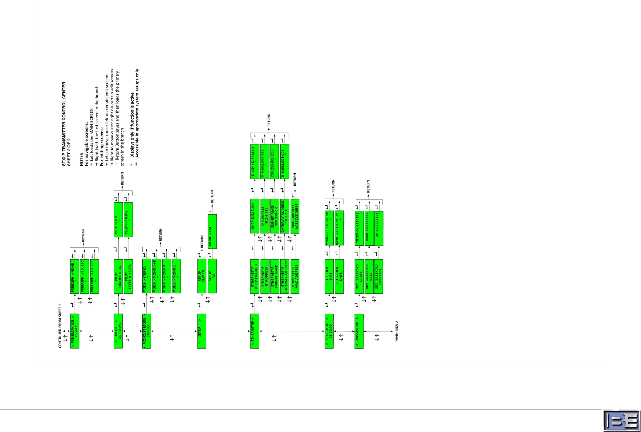
©2013 Broadcast Electronics
Figure 4 – Transmitter Control Center Manus Sheet 2

11
©2013 Broadcast Electronics
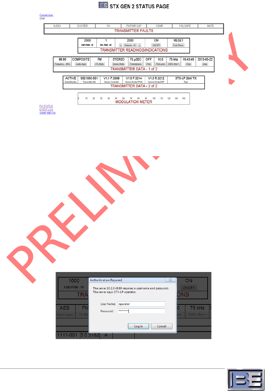
Web Page 4
The STXe comes standard with a built in HTTP web server. To load the web page, simply direct a
standard web browser to the IP assigned to the Ethernet port on the system.
Figure 5 – Web Interface Main Page
The basic settings and monitoring fields in the system are shown above in Figure 5 – Web Interface.
To cycle through the active user selection click the “Current User” link in the upper left. To access PA
monitoring information or the event log click on “PA STATUS” or “EVENT LOG” links respectively.
These can be seen in Figure 7 and Figure 8.
Posting any settings to the exciter requires an appropriate login. The graphic button objects are
disabled for user types that do not have permission to modify exciter settings. Once an adequate user
selection is made, the buttons can be clicked to display any additional options. When the change is
attempted a dialog box will pop up, which can be seen in Figure 8. Simply enter the active user type
and the correct 8-digit numerical password that goes with it to save the setting. Note: password
entry times out after 10 seconds and must be entered on the next new settings change attempt.
Valid login is remembered for the active session.
Figure 6 – Web Interface Authentication
12
©2013 Broadcast Electronics
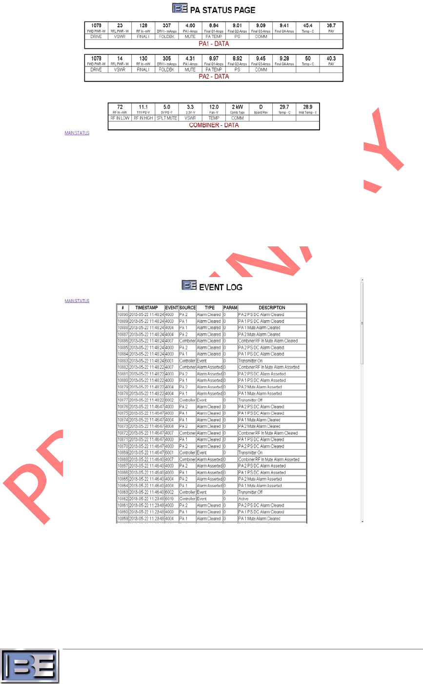
Figure 7 – Web Interface PA Page
Figure 8 – Web Interface Events Page
To check the current web page version, simply point a web browser to [IP Address]/rev.html
13
©2013 Broadcast Electronics
SNMP 5
Simple Network Management Protocol is a member of the Internet Protocol standard
communications suite. The STXe comes with a built-in SNMP agent (SNMP version 2c) for handling
all request types included in the protocol – GET, SET, GETNEXT, and GETBULK. The appropriate MIB
for the version of SNMP agent installed on the exciter must be downloaded from the exciter itself. As
with any MIB, this ASCII text file completely defines the data structure within the agent. The MIB also
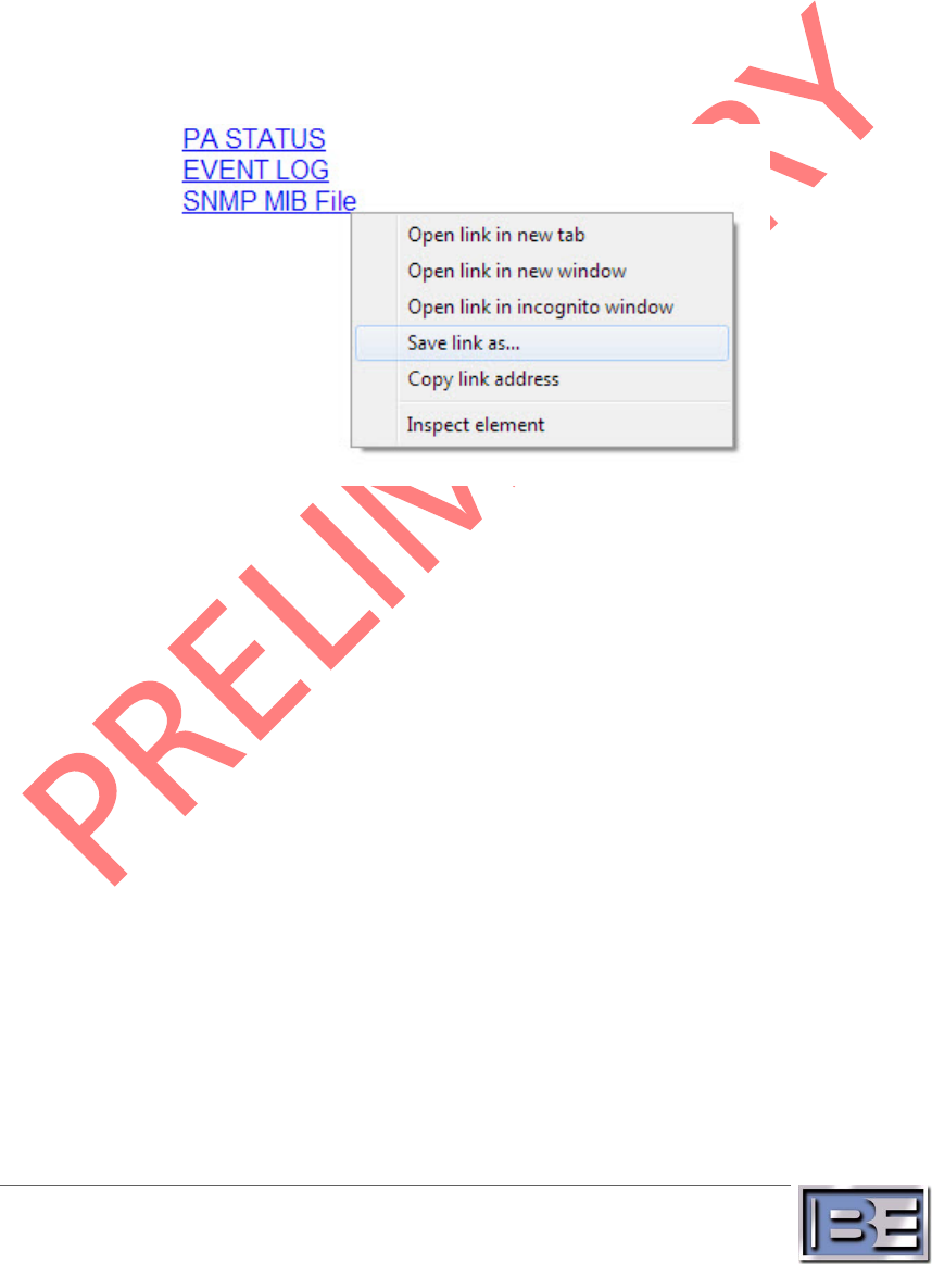
provides textual descriptions for every accessible object. To download the file access the web
interface using a standard web browser. Right click on the “SNMP MIB File” link and click “Save link
as…”, refer to Figure 9. Save a local copy of the MIB file wherever desired for use in an SNMP
manager application. Alternatively, click the link and navigate to the file in the browser. Right click
anywhere in the viewing space and click “Save as…” Simply remove the .txt extension (leaving only
the .mib extension) and save at the desired location.
Figure 9 – MIB Download
An SNMP manager application must be utilized in order to access the interface. Integrating a
manager into custom station automation programs provides countless possibilities. Alternatively,
various third party MIB browser GUI applications are available for free download; however Broadcast
Electronics does not endorse any specific application. Simply direct the manager to the Ethernet port
for communication across a network.
5.1 Authentication
Data is accessible by using the correct community strings for the desired login level. The
formula for these strings is a combination of the login type – chief, user, or operator –, a
delimitating ‘+’ character, and the 8 digit numerical password associated with that login
type. For example, “chief+12345678” in both the read community and write community
passes authentication and allows read and write to essentially every object in the MIB with
the appropriate max-access type. User and Operator login types provide more strict control
over what settings can be modified and commands issued in the system.

14
©2013 Broadcast Electronics
5.2 Objects
The SNMP interface utilizes tables wherever it makes sense to communicate data in an
indexed fashion. To accommodate a scalable transmitter product design almost all PA data is
structured as tables by using the PA number as the index. This works by appending “.1” to
the object indicating the single 60W Pa in the system. Note that a normal “leaf” node is
accessed by appending “.0” as in …38118.2.2.2.0 for system forward power.
Table 1 – SNMP Object Access
Object ID
User Access
Operator Access
Chief Access
transmitterType
Read
Read
Read/Write
serialNumber
Read
Read
Read
activeStandby
Read
Read
Read
primarySecondary
Read
Read
Read
frequency
Read
Read
Read/Write
time
Read
Read
Read/Write
date
Read
Read
Read/Write
macAddress
Read
Read
Read
useDHCP
Read
Read
Read/Write
keyTypeSNMPv3
Read
Read
Read/Write
requireSNMPv3
Read
Read
Read/Write
requireHTTPDigestAuth
Read
Read
Read/Write
ipAddress
Read
Read
Read
subnetMask
Read
Read
Read
gatewayAddress
Read
Read
Read
staticIPAddress
Read
Read
Read/Write
staticSubnetMask
Read
Read
Read/Write
staticGatewayAddress
Read
Read
Read/Write
userPassword
Read/Write
Read/Write
Read/Write
operatorPassword
None
Read/Write
Read/Write
chiefPassword
None
None
Read/Write
transmitterIsOn
Read
Read
Read
systemForwardPower
Read
Read
Read
systemReflectedPower
Read
Read
Read
transmitterOnOff
Read
Read/Write
Read/Write
currentPowerMode
Read
Read
Read
autoPowerMode
Read
Read
Read
defaultPowerMode
Read
Read
Read/Write
setpointCurrent
Read
Read/Write
Read/Write
setpointFM
Read
Read/Write
Read/Write
setpointFmDigital
Read
Read/Write
Read/Write
setpointDigital
Read
Read/Write
Read/Write
setpointCurrentMin
Read
Read
Read
setpointFMMin
Read
Read
Read
setpointFmDigitalMin
Read
Read
Read
setpointDigitalMin
Read
Read
Read
setpointCurrentMax
Read
Read
Read
setpointFMMax
Read
Read
Read
setpointFmDigitalMax
Read
Read
Read
setpointDigitalMax
Read
Read
Read

15
©2013 Broadcast Electronics
Object ID
User Access
Operator Access
Chief Access
inputSelect
Read
Read
Read/Write
peakModulationDeviation
Read
Read
Read/Write
preemphasis
Read
Read
Read/Write
monoStereoMode
Read
Read
Read/Write
modulationPeakHold
Read
Read
Read
stereoGeneratorPeakHold
Read
Read
Read
compositeAdjust
Read
Read
Read/Write
compositeDB
Read
Read
Read
compositePeakHold
Read
Read
Read
analogLAdjust
Read
Read
Read/Write
analogLDB
Read
Read
Read
analogLPeakHold
Read
Read
Read
analogRAdjust
Read
Read
Read/Write
analogRDB
Read
Read
Read
analogRPeakHold
Read
Read
Read
sca1OnOff
Read
Read
Read/Write
sca1Adjust
Read
Read
Read/Write
sca1DB
Read
Read
Read
sca2OnOff
Read
Read
Read/Write
sca2Adjust
Read
Read
Read/Write
sca2DB
Read
Read
Read
rdsOnOff
Read
Read
Read/Write
rdsAdjust
Read
Read
Read/Write
rdsDB
Read
Read
Read
analogLRLevel
Read
Read
Read/Write
aesLevel
Read
Read
Read/Write
pilotOnOff
Read
Read
Read/Write
pilotLevel
Read
Read
Read/Write
clock10MhzStatus
Read
Read
Read
clock10MhzLock
Read
Read
Read
clock1PPS
Read
Read
Read
afcLock
Read
Read
Read
afcUnlock
Read
Read
Read
modulationSilence
Read
Read
Read
audioInputSilence
Read
Read
Read
audioSilenceThreshold
Read
Read
Read/Write
audioSilencePeriod
Read
Read
Read/Write
exciterCommunications
Read
Read
Read
paForwardPower
Read
Read
Read
paReflectedPower
Read
Read
Read
paPowerSetpoint
Read
Read
Read/Write
paRfInPower
Read
Read
Read
paAlarmStatus
Read
Read
Read
paAlarmPowerSupplyDC
Read
Read
Read
paAlarmFoldbackReflectedPower
Read
Read
Read
paAlarmFoldbackTemperature
Read
Read
Read
paAlarmFoldbackCurrent
Read
Read
Read
paAlarmMutedInput
Read
Read
Read
paAlarmRailed
Read
Read
Read

16
©2013 Broadcast Electronics
Object ID
User Access
Operator Access
Chief Access
paFaultStatus
Read
Read
Read
paFaultPowerSupply
Read
Read
Read
paFaultReflectedPower
Read
Read
Read
paFaultVSWR
Read
Read
Read
paFaultTemperature
Read
Read
Read
paFaultCurrentDriver
Read
Read
Read
paFaultCurrentIPA
Read
Read
Read
paFaultCurrentFinal1
Read
Read
Read
paFaultCurrentFinal2
Read
Read
Read
paFaultCurrentFinal3
Read
Read
Read
paFaultCurrentFinal4
Read
Read
Read
paFaultHardware
Read
Read
Read
paFaultCommunication
Read
Read
Read
paTemperature
Read
Read
Read
paPsVoltage
Read
Read
Read
paDriveCurrent
Read
Read
Read
paIPACurrent
Read
Read
Read
paFinal1Current
Read
Read
Read
paFinal2Current
Read
Read
Read
paFinal3Current
Read
Read
Read
paFinal4Current
Read
Read
Read
paTotalCurrent
Read
Read
Read
combinerForwardPower
Read
Read
Read
combinerReflectedPower
Read
Read
Read
splitterRFInputPower
Read
Read
Read
splitterConfigID
Read
Read
Read
splitterBoardRev
Read
Read
Read
splitterAlarmInputMute
Read
Read
Read
splitterAlarmInputOverdrive
Read
Read
Read
splitterAlarmOutputMuted
Read
Read
Read
combinerFaultReflectedPower
Read
Read
Read
combinerFaultVSWR
Read
Read
Read
combinerFaultTemperature
Read
Read
Read
combinerFaultConfig
Read
Read
Read
combinerFaultHardware
Read
Read
Read
combinerFaultCommunication
Read
Read
Read
splitterCombinerPs11V
Read
Read
Read
splitterCombinerPs5V
Read
Read
Read
splitterCombinerPs3_3V
Read
Read
Read
combinerFan
Read
Read
Read
combinerTemperatureInternal
Read
Read
Read
combinerTemperatureInlet
Read
Read
Read
failsafe
Read
Read
Read
muteInput
Read
Read
Read
fmMode
Read
Read
Read
fmDigitalMode
Read
Read
Read
digitalMode
Read
Read
Read
systemReflectedPowerOutput
Read
Read
Read
paTotalCurrentOutput
Read
Read
Read
paTemperatureOutput
Read
Read
Read

17
©2013 Broadcast Electronics
Object ID
User Access
Operator Access
Chief Access
systemFaultOutput
Read
Read
Read
vswrSystemOutput
Read
Read
Read
transmitterOnOutput
Read
Read
Read
transmitterOffOutput
Read
Read
Read
muteOutput
Read
Read
Read
afcLockOutput
Read
Read
Read
paPsFaultOutput
Read
Read
Read
paFaultOutput
Read
Read
Read
paForwardPowerOutput
Read
Read
Read
paReflectedPowerOutput
Read
Read
Read
systemForwardPowerOutput
Read
Read
Read
paVoltageOutput
Read
Read
Read
controllerSoftware
Read
Read
Read
controllerHardware
Read
Read
Read
splitterCombinerSoftware
Read
Read
Read
splitterCombinerHardware
Read
Read
Read
paSoftware
Read
Read
Read
paHardware
Read
Read
Read
frontPanelSoftware
Read
Read
Read
frontPanelHardware
Read
Read
Read
systemFaultReset
Read
Read/Write
Read/Write
failsafeStatus
Read
Read
Read
mute
Read
Read
Read
systemAlarm
Read
Read
Read
systemFault
Read
Read
Read
exciterAlarm
Read
Read
Read
exciterFault
Read
Read
Read
paAlarm
Read
Read
Read
paFault
Read
Read
Read
paPsFault
Read
Read
Read
splitterCombinerAlarm
Read
Read
Read
splitterCombinerFault
Read
Read
Read
vswrFault
Read
Read
Read
eventTimestamp
Read
Read
Read
eventType
Read
Read
Read
eventSource
Read
Read
Read
eventCode
Read
Read
Read
eventParam
Read
Read
Read
eventLogEntryOldest
Read
Read
Read
eventLogEntryNext
Read
Read
Read
eventLogClear
Read
Read
Read/Write

18
©2013 Broadcast Electronics
Backup Control Modes 6
STXe systems come equipped with two backup control methods. Emergency control mode is
integrated standard with all systems and simply allows the system to continue functioning in the
event of a system controller failure. The backup system control and exciter feature utilizes an entire
STXe system to also allow for full control interfacing with an identical standby exciter.
6.1 Emergency Control Mode
In the event of a loss in communications with the system controller, all sub-systems enter
emergency control mode. Behavior when in this mode depends on user specified emergency
power levels. This must be set to the desired emergency power level in order to enable the
feature, which comes from the factory set at 0 W and is effectively disabled. The system will
continue to function at full emergency power as long as the exciter maintains drive to the
power amplifier. The power amplifier can only enter emergency power mode from a working
state, so it will not unmute or initialize in the emergency power state.
6.2 Standby System Control and Exciter
For complete exciter redundancy an exciter switcher kit can be acquired. These kits supply all
required hardware for utilization of standby STXe systems. The switcher system is then
paired with a second fully functional two rack unit STXe system.
Detailed information including installation and operation of this optional configuration are
contained in an Application Guide. A copy is included in standard kits and/or inserted in the
front of the binder containing this manual if shipped as part of the same order. For
electronic copies of this and any other technical documentation please visit
http://www.bdcast.com/information-center/ and follow navigation on the left side of the
page – authorized login is required.

19
©2013 Broadcast Electronics
Troubleshooting 7
Some basic information and troubleshooting steps are included below. If problems persist after basic
troubleshooting steps are taken, please contact RF Technical Services. Contact information is located
on our website at www.bdcast.com and on page iii in the front of this manual.
A fault in any part of the system indicates a complete disruption in normal operation of at least one
part of the system. A fault reset command should always be issued through diagnostics in any user
interface to correct fault conditions once the problem has been identified. If the reset is not
successful or a condition that caused a fault still remains, the fault will re-assert.
An alarm typically indicates an abnormal condition that is expected or should resolve itself. Alarms in
unexpected situations could indicate serious conditions. Alarms that persist for long periods of time
or unexpectedly appear on a regular basis should not be ignored. To get a good feel for what alarms
are expended under which conditions, see the alarm details in the sections that follow.
7.1 Event Log
The system event log can be accessed through the web interface log page or in its raw form
through the eventLog tree in SNMP. An event is defined by its index starting with the first
saved event at index 1, a timestamp from the system’s internal real time clock, an event
identification number, and the sub-system where the event triggered. Some events also have
context-based parameters that are embedded in the description of the event.
7.2 Standby
The STXe Exciter comes with built-in functionality for a standby controller and exciter – see
section 6.2 Standby System Control and Exciter. A system that is in standby is muted and not
actively controlling the transmitter. This mode is not intended in a setup that has a single
system controller and exciter. Standby system control and exciter setups should also be able
to have no more than one unit active at a time.
If a system is stuck in standby mode, this typically indicates a setup problem. Single system
controller and exciter setups require a stub 949-4130 that activates the transmitter. This
must be attached to the BE Interface jack, please see the appropriate section in the
installation and maintenance guide. Dual system controller and exciter setups require a
switcher system, such as our FW Exciter Switcher product series, that connects to both
assemblies through this interface. The switcher must be operated to activate one
controller/exciter.
7.3 Failsafe
An asserted failsafe input on the remote station interface is required for operation of the
system. The intended usage of this input is to make a loop that passes through safety relays
in all critical transmission system components. When any part of the transmission system
becomes unsafe, the circuit should open and de-assert the failsafe on the transmitter. When
a failsafe condition is active, check all systems that are wired into the failsafe circuit.

20
©2013 Broadcast Electronics
7.4 Mute
A mute refers to a lack of an RF source in some part of the system, and the affected part
depends on the context of the notification. Mute indications can happen at various stages
for different reasons, and details in system sections below should be considered.
Transmitter mute conditions typically refer to the FM exciter. In internal exciters this
commonly occurs when:
• There is no power to the exciter
• The transmitter is turned off
• The mute input pin on the remote station interface is asserted
• Failsafe input is not asserted
• The BE Interface active input is not asserted
7.5 Internal Exciter Diagnostics
Table 2 – Exciter Diagnostics Details
Fault/Alarm
Description
AFC Unlock Alarm
Automatic frequency control system does not yet have lock.
Modulation Silence
Alarm
This alarm activates when a silence condition is detected in
exciter modulation.
Audio Input Silence
Alarm
This alarm activates when a silence condition is detected at the
exciter input.
Communication Fault
This fault occurs when communication between the system
controller and the internal exciter is nonfunctional.
7.6 Power Amplifier Diagnostics
Table 3 – PA Diagnostics Details
Fault/Alarm
Description
RF Power Supply Fault
This fault activates when a power source failure is detected.
Reflected Power Fault
This fault activates when a sudden increase in reflected power
is detected by hardware in the power amplifier.
VSWR Fault
This fault activates when the measured VSWR is greater than
the maximum VSWR rating of the system any power level
Temperature Fault
This fault actives when the measured internal heat sink
temperature exceeds the safe limit
Current Fault
There is current monitoring on the final stage RF amplifiers. The
PA shuts down when measured current on any of these solid
state amplifiers exceeds the safe limit.
Hardware Fault
This is an internal self-report of problems in PA control
hardware.
Communication Fault
This fault occurs when communication between the system
controller and the PA is lost.
Power Supply DC Alarm
This is a direct connection to a self-reported DC level issue in
any power supply. This asserts when the voltage is too far from
nominal. This is normal behavior when the PA is turned off for
any reason.
Reflected Power
During FM only operation, the PA attempts to lower its output

21
©2013 Broadcast Electronics
Fault/Alarm
Description
Foldback Alarm
power when reflected power approaches dangerous levels. This
keeps the transmitter running at reduced power in order to
prevent a reflected power fault.
Temperature Foldback
Alarm
During FM only operation, the PA attempts to lower its output
power when the internal heat sink temperature approaches
dangerous levels. This keeps the transmitter running at reduced
power in order to prevent a temperature fault.
Current Foldback Alarm
During FM only operation, the PA attempts to lower its output
power when the final power transistor current approaches
dangerous levels. This keeps the transmitter running at reduced
power in order to prevent a current fault.
Muted Input Alarm
This alarm activates as a hardware failsafe mechanism when
the measured exciter drive input is below the minimum
threshold for safe operation. The approximately 10 mW
threshold is only for FM-only mode.
Railed Alarm
During FM only operation this indicates a condition where
automatic power control has reached its highest or lowest
possible control value indicating a lack of proper controllability.

22
©2013 Broadcast Electronics
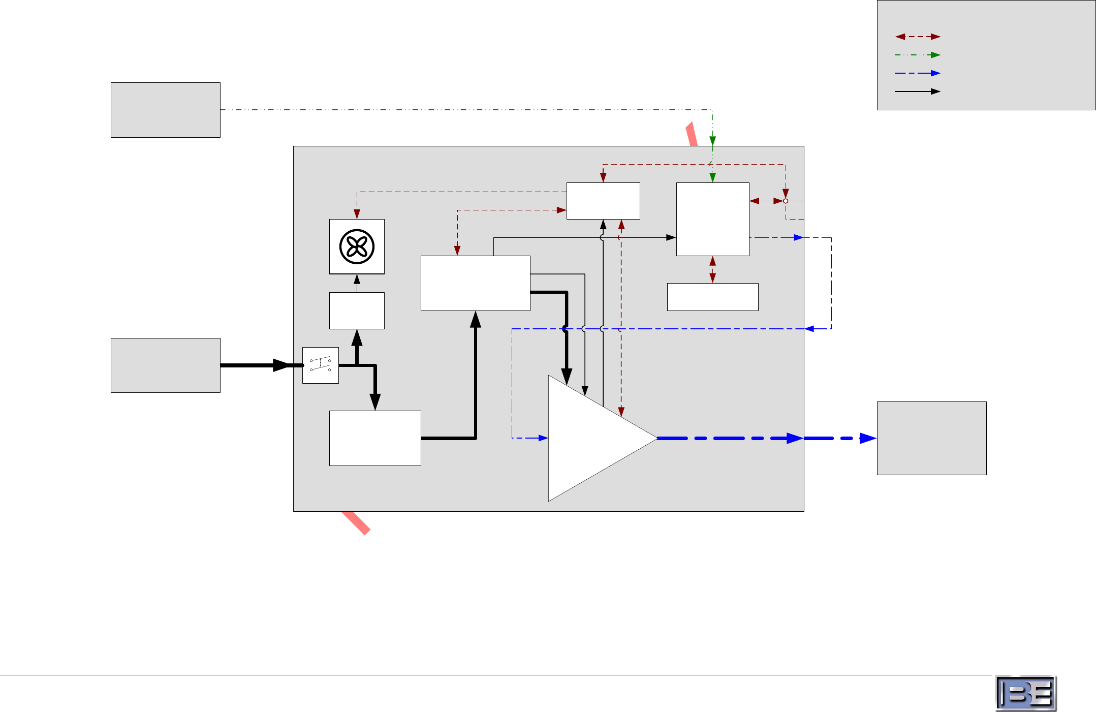
23
©2013 Broadcast Electronics
AC POWER SOURCE
ANTENNA/
TRANSMITTER
PROGRAM SERVICE
SOURCE(S)
STXe60 ASSEMBLY
RF POWER
AMPLIFIER
PA CONTROL
CONTROL
INTERFACES
SYSTEM
CONTROLLER/
EXCITER
CONTROL
COMMUNICATIONS
AUDIO CHANNEL(S)
RF PATH
AC OR DC POWER
KEY
FAN
POWER
SUPPLY
POWER REGULATOR
MAIN POWER
SUPPLY
Figure 10 – STXe60 System Block Diagram