BEI Electronics RPU-60W-150S RPU Transmitter User Manual SRPT 30
BEI Electronics, LLC RPU Transmitter SRPT 30
UserManual.wiki
>
BEI Electronics
>
RPU-60W-150S User Manual
>
Revised Manual
Contents
1.
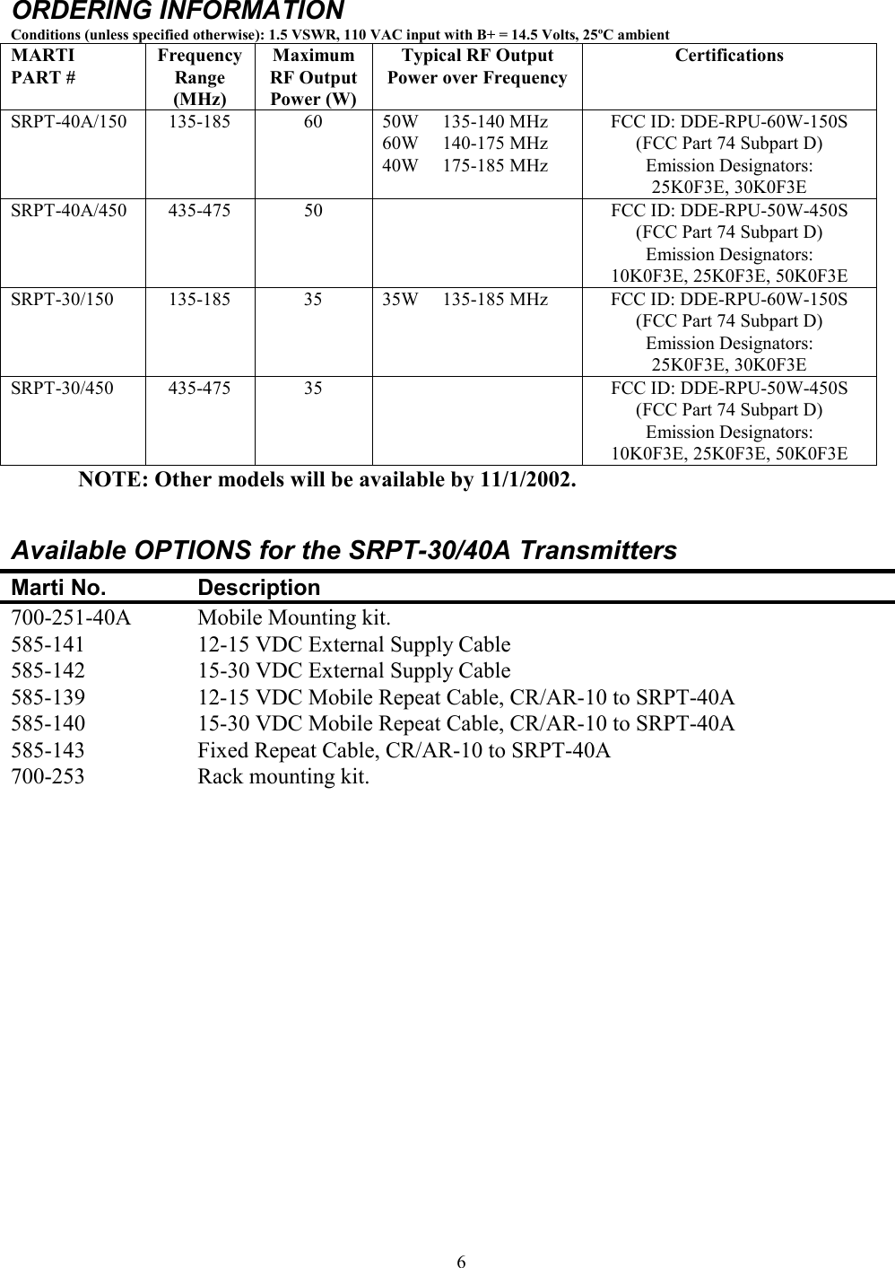
MANUAL
2.
Revised Manual
3.
Corrected rf exp manual statement
Revised Manual
Navigation menu
Upload a User Manual
Namespaces
Wiki Guide
HTML
PDF
Info
Views
User Manual
Discussion / Help
Navigation
![iiWARNINGTHIS EQUIPMENT MUST BE OPERATED WITH A 3-PRONGGROUNDED OUTLET RECEPTACLE. FAILURE TO USE APROPERLY GROUNDED OUTLET MAY RESULT IN IMPROPEROPERATION OR SAFETY HAZARD!LIMITED WARRANTYThe Seller warrants that, at the time of shipment, the products manufactured by the Seller are free from defects inmaterial and workmanship. The Seller's obligation under this warranty is limited to replacement or repair of suchproducts which are returned to Marti at its factory, transportation prepaid and properly insured, provided:a. Notice of the claimed defect is given to Marti within one (1) year [two (2) years for STL systems] from date oforiginal shipment and goods are returned in accordance with Marti instructions.b. Equipment, accessories, tubes and batteries not manufactured by Marti are subject to only such adjustments asMarti may obtain from the supplier thereof.c. This warranty does not apply to equipment which has been altered, improperly handled, or damaged in any way.The Seller is in no event liable for consequential damages, installation cost or other costs of any nature as a result of theuse of the products manufactured or supplied by the Seller, whether used in accordance with instructions or not.This warranty is in lieu of all others, either expressed or implied. No representative is authorized to assume for the Sellerany other liability in connection with Seller's products.MAILING & SHIPPING ADDRESS:Broadcast ElectronicsMARTI Electronics Division4100 North 24th StreetQuincy, IL 62301The United States of AmericaCOPYRIGHT NOTICE©2001 All Rights ReservedMarti Electronics1st printing, June 2001No part of this manual may be reproduced, transmitted, transcribed, stored in a retrieval system , or translated into anylanguage, natural or computer, in any form or by any means, without the prior written permission of Marti Electronics.](https://usermanual.wiki/BEI-Electronics/RPU-60W-150S.Revised-Manual/User-Guide-274074-Page-3.png)