BEST 40H Door 4 Part.p65 Installation 45HW & 47HW Electrified Mortise Locks H15 T81163a
User Manual: BEST Installation 45HW & 47HW Electrified Mortise Locks Installation
Open the PDF directly: View PDF ![]() .
.
Page Count: 2
Rev date Template
number
Rev
Title
To ensure accurate door preparation, use only factory-printed templates. Do not use copies or facsimilies. T81163/Rev A 1904683 ER-7991-42 July 2006
BacksetSeries Trim style Door thickness
BEST ACCESS SYSTEMS
Installation Template for 45H & 47H Mortise Locks
and 45HW & 47HW Electrified Mortise Locks
H, J, M,
N, R, S 7/2006 H15H15
H15H15
H15 AA
AA
A
2 3/4”
45H & 47H
45HW & 47HW 1 3/4”
Select, mark, and
drill holes
1 Refer to the Holes by Function
table and the figure below to
determine the holes to be
drilled for the lock function and
trim combination.
2 Determine the inside and
outside, hand, and bevel of the
door.
3 Position one of the door edge
templates on the door, making
sure that the lock case mortise
shown on the template aligns
with the mortise pocket
prepared in the door. Tape the
template to the door.
Note: For metal doors, see the
H16 Template (T81166) or the
H19 Template (T81611).
4 Using the centerlines on the
door edge template as a guide,
position the appropriate door
template on each side of the
door. You need to take the bevel
into account. Tape the
templates to the door.
5 Center punch the appropriate
drill points.
6 Drill the holes. See the
Installation Instructions for 45H &
47H Mortise Locks (T81162) or
the Installation Instructions for
45HW & 47HW Electrified Mortise
Locks (T81612).
Note: For electrified locks that
require concealed wiring, a 3/8”
diameter channel through the
door is required.
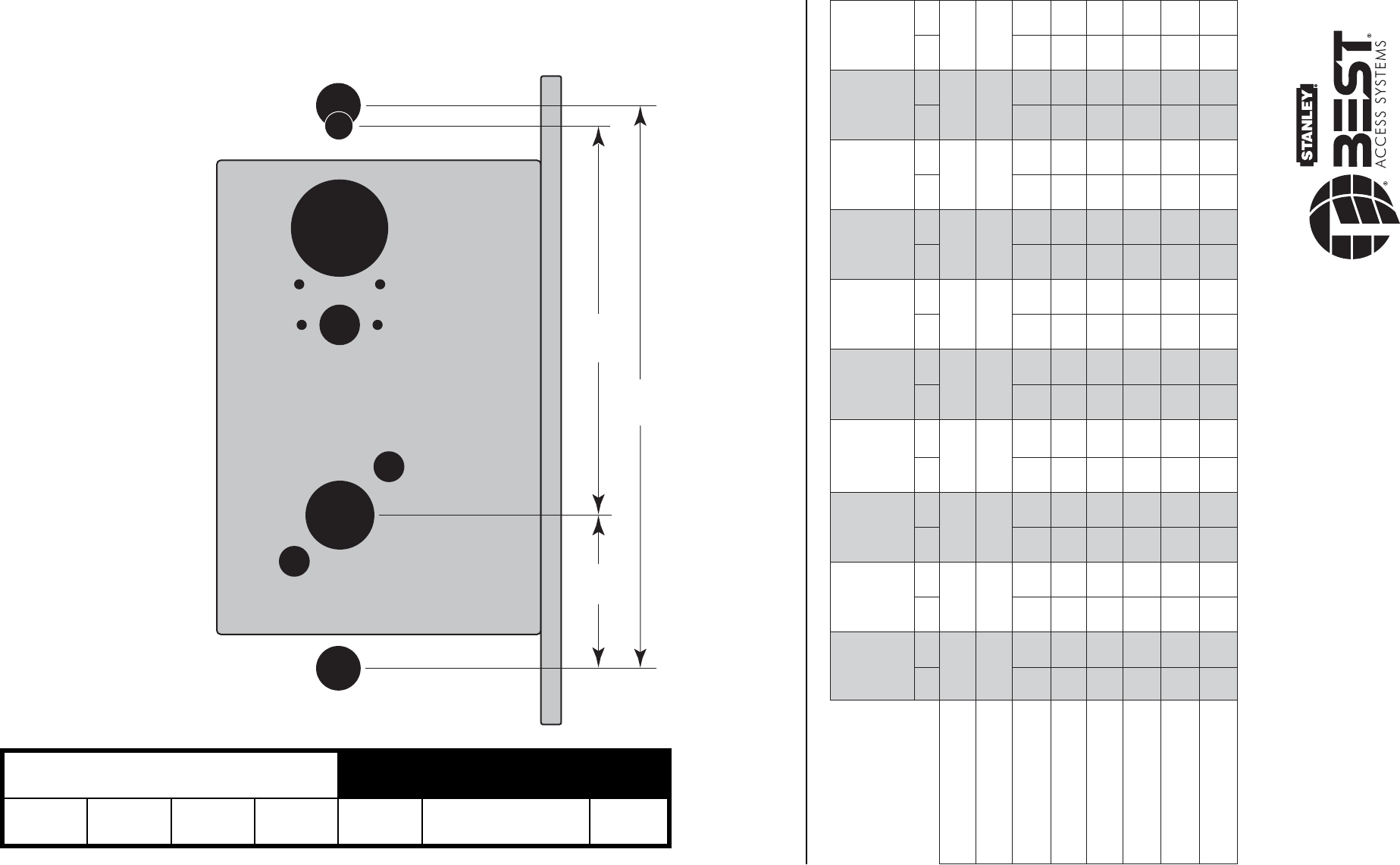
Holes by Function
1 49/64 in
(44.8 mm)
6
59
/
64
in
(175.8 mm)
4 7/8 in
(123.8 mm)
A
B
C / D
EE
F
G
G
H
A
JJ
snoitcnuF
,R,D,A
,5B,BHR
UED,LED
,B,TA,BA
,JH,WB,AB
,DT,AT,T
UEDT,LEDT
DA
,G,BHC,C
,S,LNI,DNI
,LEWT,7B,W
,LEW,UEWT
,UEW
H,TL,BL,L
UEL,LEL
,XN,N
UEXN,LEXN DW,DR DY TD2,TD1
llirdotseloH
S/I S/OS/IS/O S/I S/OS/IS/O S/I S/OS/IS/O S/I S/OS/IS/O S/I S/OS/IS/O
A
mirtdegrofN&M
)seloh2( *
hguorhT
rood
hguorhT
rood
hguorhT
rood
hguorhT
rood
hguorhT
rood
hguorhT
rood
hguorhT
rood
hguorhT
rood
hguorhT
rood
hguorhT
rood
†
B
mirtJ *hguorhT
rood
hguorhT
rood
hguorhT
rood
hguorhT
rood
hguorhT
rood
hguorhT
rood
hguorhT
rood
†
C
D
rednilycdradnatS ro
rednilycytiruceshgiH
‡
■■■■ ■ ■■■ ■
E
nrutbmuhtmirtS&,R,H
)seloh2(wercsgnitnuom *
■ ■ ■ ■
F
/yekycnegremE
sseccanrutbmuht
■ ■ ■ ■■■
G
)seloh2(gnitnuommirT
††
■■■■ ■■■■■■■ ■ ■
†
■
H
reveL
††
■■■■ ■■■■■■■ ■
J
rotacidnilausivmirtR&H
)seloh2(wercsgnitnuom *
■
*.epytmirtnodesabselohmirtenimreteD
sahcus(snoitcnufylnoedisnimirtdna)RZdnaDZsahcus(snoitcnufylnoedist
uomirtroF
.dedeensaroodehtfoedismirtehtnoselohmirttnuomecafruseraperp,)RXdnaDX
†
.detacidnistniopretnecehttaroodehtotniyawflahseloh)mm11(.ni46/7llird,TD1roF
‡
.rednilyc4J7E1ehtdnanoehctucseMehtesu,gnitsilytiruceshgih734LUehtrofyfilauqoT
yfilauqtonseodtub,mirtla
noitcesromirtMrehtiehtiwesurofelbaliavasirednilyc4K7E1ehT
.skcolnoitcnufJHdnaHrofelbaliavatonsinoitpos
ihT.gnitsilytiruceshgih734LUehtrof
††
ebelohhcaetahtdednemmocersiti,tekcopesitromehthguorhtssapselohesehtesuaceB
.hguorhtthgiartsnahtrehtary
letarapesdellird
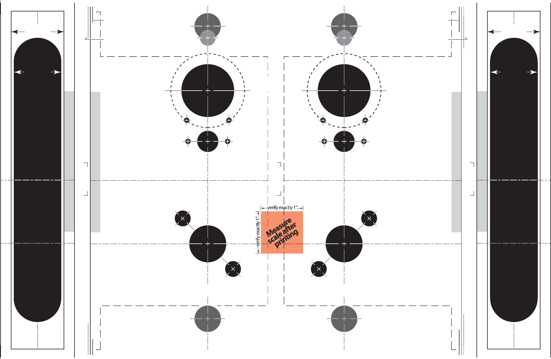
To ensure accurate door preparation, use only factory-
printed templates. Do not use copies or facsimilies.
Vertical centerline
of lever
H
G
A
Horizontal centerline
of lock
G3/8 in
10 mm
7/8 in
23 mm
3/8 in
10 mm
5/8 in
16 mmA
B
DC
1 3/4 in
45 mm
1 1/4 in
32 mm
EF
1/8 in
3 mm
1/2 in
13 mm
E
Horizontal centerline
of lever
3/8 in
10 mm
Vertical centerline
of lever
Horizontal centerline
of lock
5/8 in
16 mmA
B
DC
1 3/4 in
45 mm
1 1/4 in
32 mm
G3/8 in
10 mm
H7/8 in
23 mm
G
A
Horizontal centerline
of lever
1 1/8 in
29 mm
1 1/4 in
32 mm
Horizontal centerline
of lock
Vertical
centerline
of lock
Lock case mortise
1 1/4 in
32 mm
1 1/8 in
29 mm
Horizontal centerline
of lock
Lock case mortise
Vertical
centerline
of lock
Horizontal centerline
of lever
Horizontal centerline
of lever
Align to edge of door.
Low edge (narrow side)
High edge (wide side)
Hole Descriptions
AM & N forged
trim (2)
BJ trim (1)
CCylinder (1)
DHigh security
cylinder (1)
EH, R, & S trim
thumb turn
mounting screw (2)
FEmergency key /
thumb turn
access (1)
GTrim mounting (2)
HLever (1)
JH & R trim
visual indicator
mounting screw (2)
Note: Use this template for the inside of a
LH or LHRB door or the outside (keyed
side) of a RH or RHRB door. For metal
doors, see the H16 Template—Installation
Specifications for 45H & 47H Mortise Locks
(T81166) or the H19 Template—Installation
Specifications for 45HW & 47HW Electrified
Mortise Locks (T81611).
Note: Use this template for the inside of a
RH or RHRB door or the outside (keyed
side) of a LH or LHRB door. For metal
doors, see the H16 Template—Installation
Specifications for 45H & 47H Mortise Locks
(T81166) or the H19 Template—Installation
Specifications for 45HW & 47HW Electrified
Mortise Locks (T81611).
Detach here
Detach here
Detach here
Align to edge of door.
Low edge (narrow side)
High edge (wide side)
Strike lip
Strike lip
Strike lip
Strike lip
Hole Descriptions
AM & N forged
trim (2)
BJ trim (1)
CCylinder (1)
DHigh security
cylinder (1)
EH, R, & S trim
thumb turn
mounting screw (2)
FEmergency key /
thumb turn
access (1)
GTrim mounting (2)
HLever (1)
JH & R trim
visual indicator
mounting screw (2)
JJ1/8 in
3 mm
EF
1/8 in
3 mm
1/2 in
13 mm
E
JJ1/8 in
3 mm
