BEST 40H Series Service Manual T81602b40H
H Service Manual 40_H_Service_ManualT81602b Service Manual
User Manual: BEST 40H Series Service Manual Installation
Open the PDF directly: View PDF ![]() .
.
Page Count: 196 [warning: Documents this large are best viewed by clicking the View PDF Link!]
- Contents
- Figures
- 1 Getting Started
- 2 Introducing the 40H Lock
- 3 Lock Functions
- 4 Mortise Case Parts
- A function case-office lock
- AT function case-office lock R function case-classroom lock C function case-public entrance lock W function case-storeroom lock
- D function case-storeroom lock ZD function case-storeroom lock
- INL function case-intruder lock XR function case-classroom lock
- LT function case-privacy lock
- N function case-passage lock
- NX function case-exit lock
- CHB function case-holdback lock
- RHB function case-classroom holdback lock
- AB function case-office lock
- B function case-entrance lock
- BA function case-entrance lock
- S function case-storeroom lock
- BW function case-entrance lock
- G function case-communicating lock
- B5 function case-entrance lock
- B7 Function case-entrance lock
- H function case-hotel lock
- HJ function case-hotel lock
- TD function case-dormitory lock
- IND function case-intruder lock
- T function case-dormitory lock
- L function case-privacy lock
- LB function case-privacy lock
- TA function case-dormitory lock
- AD function case-deadlock
- WD function case-deadlock
- YD function case-deadlock
- RD function case-classroom deadlock
- DEL function case-Electrically locked fail safe lock
- DEU function case-Electrically unlocked fail secure
- WEL function case-Electrically unlocked fail safe
- WEU function case-Electrically unlocked fail secure
- NXEL function case-electrically locked fail safe lock
- NXEU function case-electrically unlocked fail secure lock
- TDEL function case-Electrically locked fail safe lock
- TDEU function case-Electrically unlocked fail secure
- TWEL function case-Electrically locked fail safe lock
- TWEU function case-Electrically unlocked fail secure
- LEL function case-Electrically locked fail safe lock
- LEU function case-Electrically unlocked fail secure
- Case only locks
- 5 Trim Parts
- 6 Service and Maintenance
- 7 48H & 49H Locks
- A Glossary
- B Installation Instructions
- 45H & 47H Mortise Locks
- Contents
- Finishing the door preparation
- Configuring & installing the mortise case
- Installing the trim
- 9 Install trim mounting plates
- 10 Install concealed cylinder (N trim only)
- 11 Install roses or escutcheons
- 12 Install thumb turn or emergency access plate (if necessary)
- 13 Install visual indicator trim (H or R sectional trim)
- 14 Install standard or high security cylinder (if necessary)
- 15 Install inside and outside levers
- Finishing the installation
- Using the latch holdback feature
- 45HW & 47HW Electrified Mortise Locks
- Contents
- Finishing the door preparation
- 1 Identify holes to drill
- 2 Align templates
- 3 Center punch and drill holes
- 4 Drill wire channel through door
- 5 Prepare door for door status switch (optional for deadbolt function locks)
- 6 Determine wire gauge for power wiring
- 7 Prepare door for wire transfer hinge and run field wiring
- 8 Install door status switch (optional for deadbolt function locks)
- Configuring & installing the mortise case
- Installing the trim
- Finishing the installation
- 48H & 49H Mortise Locks
- 45H & 47H Mortise Locks
- C Index
CREDITS/COPYRIGHT
Copyright ©2006–2007 Stanley Security Solutions, Inc. and Stanley Logistics, Inc. All
rights reserved. Printed in the United States of America.
Information in this document is subject to change without notice and does not
represent a commitment on the part of Stanley Security Solutions, Inc. The software
described in this document are furnished under a license agreement or nondisclosure
agreement.
This publication is intended to be an accurate description and set of instructions
pertaining to its subject matter. However, as with any publication of this complexity,
errors or omissions are possible. Please call your BEST® distributor or Stanley Security
Solutions, Inc., Best Access Systems at (317) 849-2250 if you see any errors or have any
questions. No part of this manual and/or databases may be reproduced or transmitted
in any form or by any means, electronic or mechanical, including photocopying,
recording, or information storage and retrieval systems, for any purpose, without the
express written permission of Stanley Security Solutions, Inc.
This document is distributed as is, without warranty of any kind, either express or
implied, respecting the contents of this book, including but not limited to implied
warranties for the publication’s quality, performance, merchantability, or fitness for any
particular purpose. Neither Stanley Security Solutions, Inc., nor its dealers or
distributors shall be liable to the user or any other person or entity with respect to any
liability, loss, or damage caused or alleged to be caused directly or indirectly by this
publication.
The Life Safety Code is a registered trademark of the National Fire Protection
Association.
Written and designed by Stanley Security Solutions, Inc. and Avalon Group, Inc.,
Indianapolis, Indiana.
T81602 Rev B 1922545 ER-7991-6 March 2007

40H Series Service Manual iii
CONTENTS
FIGURES 1–IX
GETTING STARTED 1–1
Introduction 1–1
Certifications and standards 1–1
45H & 47H overview 1–2
Lock characteristics 1–2
Lock dimensions 1–2
45HW & 47HW overview 1–4
Lock characteristics 1–4
Lock dimensions 1–4
48H & 49H overview 1–6
Lock characteristics 1–6
Lock dimensions 1–6
Documentation package 1–8
Technical support 1–8
Support services 1–8
Telephone technical support 1–8

CONTENTS
iv 40H Series Service Manual
INTRODUCING THE 40H LOCK 2–1
Overview 2–1
Ways to order 2–1
Function-specific locks 2–1
Universal locks 2–2
Three-part locks 2–2
The advantage of kits 2–2
Working with universal functions 2–2
Working with trim kits 2–3
Trim one side locks 2–5
LOCK FUNCTIONS 3–1
45H & 47H Functions by ANSI designation & lock function quick reference 3–2
45HW & 47HW lock function quick reference 3–3
Function descriptions 3–4
Single-keyed functions 3–5
Double-keyed functions 3–8
Deadlocked functions 3–10
Non-keyed functions 3–11
Special functions 3–13
Electrified functions 3–14
MORTISE CASE PARTS 4–1
A function case—office lock 4–2
AB function case—office lock 4–14
AD function case—deadlock 4–34
AT function case—office lock 4–4
B function case—entrance lock 4–16
B5 function case—entrance lock 4–22
B7 Function case—entrance lock 4–22
BA function case—entrance lock 4–18
BW function case—entrance lock 4–20
C function case—public entrance lock 4–4
CHB function case—holdback lock 4–12
D function case—storeroom lock 4–4
DEL function case—Electrically locked fail safe lock 4–38
DEU function case—Electrically unlocked fail secure 4–40
G function case—communicating lock 4–22
H function case—hotel lock 4–24
HJ function case—hotel lock 4–24
IND function case—intruder lock 4–26

CONTENTS
40H Series Service Manual v
INL function case—intruder lock 4–4
L function case—privacy lock 4–28
LB function case—privacy lock 4–30
LEL function case—Electrically locked fail safe lock 4–58
LEU function case—Electrically unlocked fail secure 4–60
LT function case—privacy lock 4–6
N function case—passage lock 4–8
NX function case—exit lock 4–10
NXEL function case—electrically locked fail safe lock 4–46
NXEU function case—electrically unlocked fail secure lock 4–48
R function case—classroom lock 4–4
RD function case—classroom deadlock 4–36
RHB function case—classroom holdback lock 4–12
S function case—storeroom lock 4–18
T function case—dormitory lock 4–26
TA function case—dormitory lock 4–32
TD function case—dormitory lock 4–24
TDEL function case—Electrically locked fail safe lock 4–50
TDEU function case—Electrically unlocked fail secure 4–52
TWEL function case—Electrically locked fail safe lock 4–54
TWEU function case—Electrically unlocked fail secure 4–56
W function case—storeroom lock 4–4
WD function case—deadlock 4–34
WEL function case—Electrically unlocked fail safe 4–42
WEU function case—Electrically unlocked fail secure 4–44
XR function case—classroom lock 4–4
YD function case—deadlock 4–34
ZD function case—storeroom lock 4–4
Case only locks 4–62
How to order standard mortise locks 4–62
How to order electrified mortise locks 4–63
Case only components 4–64
TRIM PARTS 5–1
Outside trim kits 5–2
How to order 5–2
Kit components 5–3
Inside trim kits 5–6
How to order 5–6
Kit components 5–7

CONTENTS
vi 40H Series Service Manual
Strike packages 5–10
How to order 5–10
Strike packages 5–11
Lever sets 5–12
How to order 5–12
Lever sets 5–13
Faceplate kits 5–15
How to order 5–15
Faceplate kits 5–15
Replacement spindles 5–16
How to order 5–16
Replacement spindles 5–17
Screw kits 5–18
How to order 5–18
Screw kits 5–19
Cylinders and cams 5–20
How to order 5–20
Cylinders by door thickness 5–21
Cylinder ring lengths 5–21
Escutcheon assemblies 5–23
J trim outside escutcheons 5–23
J trim inside escutcheons 5–24
M & N trim outside escutcheons 5–25
M & N trim inside escutcheons 5–26
Roses and rose rings 5–27
Dummy trim 5–27
Visual indicator trim 5–28
Service equipment 5–29
Driver bits 5–30
Accessories for electrified locks 5–31
SERVICE AND MAINTENANCE 6–1
Changing the hand 6–2
Changing hand quick reference 6–2
Changing handing for the mortise case 6–2
To rotate the latchbolt: 6–2
To change the position of the hub toggles: 6–3
Changing the function for universal cases 6–5
Changing the function for UNR cases 6–5
To adjust the shuttle screw positions: 6–5
To change the position of the hub toggles: 6–6
Changing the function for UNAB cases 6–6
Changing the function for UNT cases 6–6
Troubleshooting 6–7

CONTENTS
40H Series Service Manual vii
48H & 49H LOCKS 7–1
Function quick reference 7–1
Function descriptions 7–2
48H & 49H Mortise case parts 7–2
K function case—cylinder deadlock 7–3
L function case—cylinder deadlock 7–3
M function case—cylinder deadlock 7–3
R function case—classroom deadlock 7–4
48H Trim parts 7–5
49H High security deadbolt trim parts 7–6
Strikes and strike boxes 7–7
Troubleshooting 7–8
GLOSSARY A–1
INSTALLATION INSTRUCTIONS B–1
INDEX C–1

CONTENTS
viii 40H Series Service Manual

40H Series Service Manual ix
FIGURES
GETTING STARTED
45H & 47H mortise case and strike dimensions 1–3
45HW & 47HW mortise case and strike dimensions 1–5
48H & 49H mortise case and strike dimensions 1–7
LOCK FUNCTIONS
Understanding function drawings 3–4
MORTISE CASE PARTS
A function case exploded diagram 4–2
AT, C, D, INL, R, W, ZD, XR function case exploded diagram 4–4
LT function case exploded diagram 4–6
N function case exploded diagram 4–8
NX function case exploded diagram 4–10
CHB, RHB function case exploded diagram 4–12
AB function case exploded diagram 4–14
B function case exploded diagram 4–16
BA, S function case exploded diagram 4–18
BW function case exploded diagram 4–20
G, B5, B7 function case exploded diagram 4–22
H, HJ, TD function case exploded diagram 4–24
IND, T function case exploded diagram 4–26
L function case exploded diagram 4–28
LB function case exploded diagram 4–30
TA function case exploded diagram 4–32
AD, WD, YD function case exploded diagram 4–34

Figures
x40H Series Service Manual
RD function case exploded diagram 4–36
DEL function case exploded diagram 4–38
DEU function case exploded diagram 4–40
WEL function case exploded diagram 4–42
WEU function case exploded diagram 4–44
NXEL function case exploded diagram 4–46
NXEU function case exploded diagram 4–48
TDEL function case exploded diagram 4–50
TDEU function case exploded diagram 4–52
TWEL function case exploded diagram 4–54
TWEU function case exploded diagram 4–56
LEL function case exploded diagram 4–58
LEU function case exploded diagram 4–60
Case only lock – faceplate and case for AB function shown 4–64
TRIM PARTS
OS1 – Outside lever only 5–4
OS2 – Outside lever & cylinder 5–4
OS3 – Outside lever & access plate 5–5
OS4 – Outside cylinder only 5–5
IS1 – Inside lever only 5–8
IS2 – Inside lever & thumb turn 5–8
IS3 – Inside lever & cylinder 5–8
IS4 – Inside cylinder only 5–9
IS5 – Inside thumb turn only 5–9
Lip to center dimension 5–10
Strike kit 1– Universal strike package 5–11
Strike kit 4– Strike box only 5–11
Strike kit 1– Universal strike package with flat-lipped option 5–11
Strike kit 5– Magnetic strike box only 5–11
Solid tube / return (style 3) 5–14
Knob (style 4) 5–14
Curved return (style 14) 5–14
Contour/angle return (style 15) 5–14
Curve / no return (style 16) 5–14
Faceplate kits 5–15
Spindle kit 2 – Standard replacement spindle 5–17
Spindle kit 4 – Hook replacement spindle 5–17
Screw kit components 5–19

Figures
40H Series Service Manual xi
Cylinders 5–21
Cylinder rings 5–22
Cylinder cams 5–22
Outside J trim escutcheons 5–23
Inside J trim escutcheons 5–24
Outside M & N trim escutcheons 5–25
Inside M & N trim escutcheons 5–26
Roses & rose rings 5–27
Dummy trim parts 5–27
Keyed visual indicator trim 5–28
Privacy visual indicator trim 5–28
Service equipment 5–29
Driver bits 5–30
Accessories for electrified locks 5–31
SERVICE AND MAINTENANCE
Explanation of the hand and bevel of the door 6–2
Rotating the latchbolt 6–3
Positioning the hub toggles 6–4
Positioning the shuttle screws and stop screw 6–6
48H & 49H LOCKS
Understanding function drawings 7–2
K, L, M function case 7–3
R function case 7–4
Deadbolt trim 7–5
High security deadbolt trim 7–6
Strikes and strike box 7–7

Figures
xii 40H Series Service Manual

40H Series Service Manual 1–1
1GETTING STARTED
INTRODUCTION
The 40H Series Service Manual contains essential
information to help you maintain your 40H Series
Locks.
CERTIFICATIONS AND STANDARDS
■The 40H Series Locks are listed by Underwriters
Laboratories (U.S. and Canada) for use on 3 hr.,
Alabel doors.
■The 40H Series Locks with deadbolt are certified
by Miami-Dade County Code Compliance Office
for use in applications requiring a design pressure
rating of ± 100 PSF for single doors and ± 50 PSF
for double door openings.
■The 40H Series Locks without deadbolt are
certified by Miami-Dade County Code
Compliance Office for use in applications
requiring a design pressure rating of ± 60 PSF for
single doors and ± 35 PSF for double door
openings.
■The 45HW and 47HW Locks are UL listed for
GYQS electrically controlled single point locks or
latches.
■The 45HW and 47HW Locks are approved by the
California State Fire Marshall (CSFM) pursuant to
section 13144.1 of the California Health and
Safety Board.

Getting Started
1–2 40H Series Service Manual
■The 45HW and 47HW locks are approved by the city of New York
Board of Standards and Appeals under calendar number 49-88-SA.
See CSFM listing number 4136-1175:101.
■45H Locks meet or exceed ANSI A156.13, Series 1000, Grade 1
Operational and Grade 2 Security standards, when used with the
1CD core.
■47H Locks meet or exceed ANSI A156.13, Series 1000, Grade 1
Operational and Grade 1 Security standards.
■47H Locks conform to UL437 Standard for Key Locks, referencing
Door Locks.
■49H Locks conform to ANSI 156.5, Grade 1 standards.
■The 1E7J4 cylinder used in 47H Locks conforms to UL437 Standard
for Key Locks, referencing High Security Cylinders, and is listed for
Canada as well as the United States.
■The lock case and faceplate dimensions fit the standard door
preparation as specified in ANSI A115.1.
■The strike fits the standard door frame cutout as specified in
ANSI A115.1.
■Lever styles 3, 14 and 15 conform to California Administrative Code
Title 19 and Title 24.
45H & 47H OVERVIEW
Lock
characteristics
All 45H & 47H Mortise Locks have the following characteristics:
Lock
dimensions
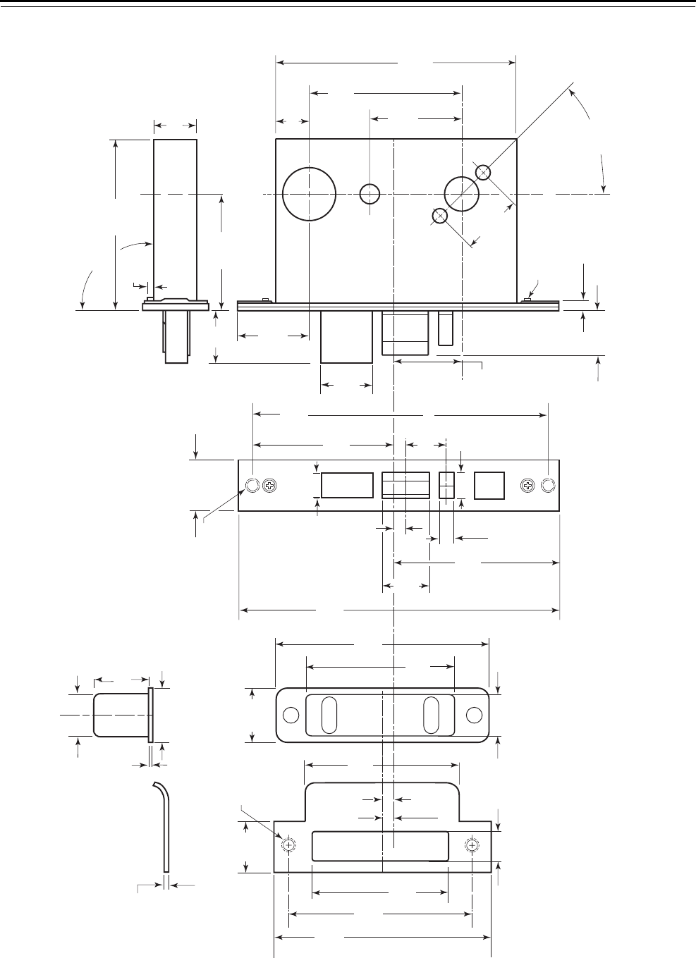
The following diagram shows the dimensions for the 45H & 47H
mortise case and strike.
Feature Dimensions
Case size 5 7/8″ × 4 1/4″ × 1″
Backset 2 3/4″
Door thickness range 1 3/4″ standard–up to 5″†
†. All mortise functions, except trim one side only functions,
can be installed on 5″ thick doors if the mortise is centered
in the door. Trim one-side-only functions can be installed
on doors up to 2 1/2″ thick if the mortise is centered in the
door.
Getting Started
40H Series Service Manual 1–3
Figure 1.1 45H & 47H mortise case and strike dimensions
3/32 in
(2.4 mm)
Strike plate —
overhead view
1 7/32 in
(31.0 mm)
31/32 in (24.6 mm)
3/64 in
(1.2 mm)
1 1/32 in
(26.2 mm)
Strike box —
overhead view
3 3/64 in
(77.4 mm)
3 3/8 in
(85.7 mm)
1 1/4 in
(31.8 mm)
3 21/64 in
(84.5 mm)
4 7/8 in
(123.8 mm)
4 1/8 in
(104.8 mm)
11/16 in
(17.5 mm)
Centerline
of lock
Centerline
of strike
40HS1
Strike plate
2 x #12–24 screw
Note 5
3/8 in
(9.5 mm)
Strike box
15/16 in
(23.8 mm)
1 7/32 in
(31.0 mm)
4 25/32 in
(121.4 mm)
1 1/8 in
(28.6 mm)
1 in (25.4 mm)
4 i n
(101.6 mm)
9/16 in
(14.3 mm)
11/32 in
(8.7 mm)
5/8 in
(15.9 mm)
8 i n
(203.2 mm)
7 1/4 in
(184.2 mm)
1 1/4 in
(31.8 mm)
Faceplate
2 x #12-24 screw
7/32 in
(5.6 mm)
3 5/8 in
(92.1 mm) 1 3/16 in
(30.2 mm)
1 7/8 in
(47.6 mm)
3/4 in
(19.1 mm)
1 1/2 in
(38.1 mm)
Centerline
of lever to
centerline
of lock
1 11/16 in
(42.9 mm)
7/32 in (5.6 mm)
13/16 in (20.6 mm)
2 27/64 in
(61.5 mm)
3 5/8 in
(92.1 mm)
5 7/8 in
(149.2 mm)
45 degrees
Clear for screws
1/16 in (1.6 mm) deep
2 3/4
in (69.9 mm)
backset
1 i n
(25.4 mm)
1/8 in
(3.2 mm)
4 1/4 in
(108.0 mm)
Mortise case — overhead view
Adjusts 90 degrees ± 3 ½ degrees
7/8 in (22.2 mm)
Mortise case — side view

Getting Started
1–4 40H Series Service Manual
45HW & 47HW OVERVIEW
Lock
characteristics
All 45HW & 47HW Mortise Locks have the following characteristics:
Lock
dimensions
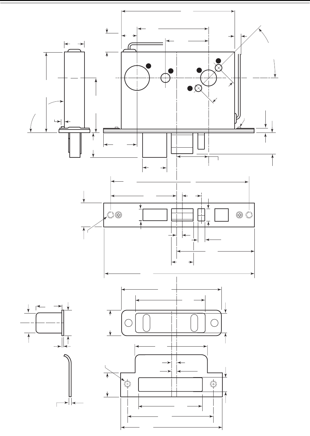
The following diagram shows the dimensions for the 45HW & 47HW
mortise case and strike.
Feature Dimensions
Case size 5 7/8″ × 4 1/4″ × 1″
Backset 2 3/4″
Door thickness range 1 3/4″ standard–up to 5″†
†. All mortise functions, except trim one side only functions,
can be installed on 5″ thick doors if the mortise is centered
in the door. Trim one-side-only functions can be installed
on doors up to 2 1/2″ thick if the mortise is centered in the
door.
Getting Started
40H Series Service Manual 1–5
Figure 1.2 45HW & 47HW mortise case and strike dimensions
3/32 in
(2.4 mm)
Strike plate —
overhead view
1 7/32 in
(31.0 mm)
31/32 in (24.6 mm)
3/64 in
(1.2 mm)
1 1/32 in
(26.2 mm)
Strike box —
overhead view
3 3/64 in
(77.4 mm)
3 3/8 in
(85.7 mm)
1 1/4 in
(31.8 mm)
3 21/64 in
(84.5 mm)
4 7/8 in
(123.8 mm)
4 1/8 in
(104.8 mm)
11/16 in
(17.5 mm)
Centerline
of lock
Centerline
of strike
40HS1
Strike plate
2 x #12–24 screw
3/8 in
(9.5 mm)
Strike box
15/16 in
(23.8 mm)
1 7/32 in
(31.0 mm)
1 1/8 in
(28.6 mm)
1 in (25.4 mm)
4 i n
(101.6 mm)
9/16 in
(14.3 mm)
11/32 in
(8.7 mm)
5/8 in
(15.9 mm)
8 i n
(203.2 mm)
7 1/4 in
(184.2 mm)
1 1/4 in
(31.8 mm)
Faceplate
2 x #12-24 screw
7/32 in
(5.6 mm)
3 5/8 in
(92.1 mm)
1 in (25.4 mm)
min. clearance
for wires
1 3/16 in
(30.2 mm)
1 7/8 in
(47.6 mm)
3/4 in
(19.1 mm)
1 1/2 in
(38.1 mm)
Centerline
of lever to
centerline
of lock
1 11/16 in
(42.9 mm)
7/32 in (5.6 mm)
13/16 in (20.6 mm)
2 27/64 in
(61.5 mm)
3 5/8 in
(92.1 mm)
5 7/8 in
(149.2 mm)
45 degrees
Clear for screws
1/16 in (1.6 mm) deep
3/8 in (9.5 mm)
clearance for wires
4 25/32 in
(121.4 mm)
2 3/4 in (69.9 mm)
backset
1 i n
(25.4 mm)
1/8 in
(3.2 mm)
4 1/4 in
(108.0 mm)
Mortise case — overhead view
Adjusts 90 degrees ± 3 ½ degrees
7/8 in (22.2 mm)
C
F
G
H
G
Mortise case — side view

Getting Started
1–6 40H Series Service Manual
48H & 49H OVERVIEW
Lock
characteristics
All 48H & 49H Mortise Locks have the following characteristics:
Lock
dimensions
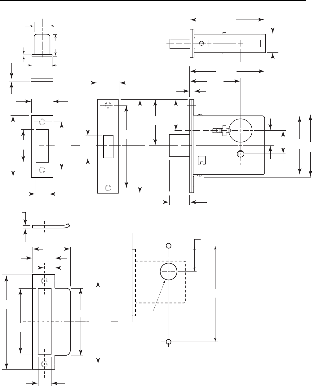
The following diagram shows the dimensions of the 48H & 49H mortise
case and strike.
Feature Dimensions
Case size 4 3/16″ × 3 5/8″ × 1″
Backset 2 3/4″
Door thickness range 1 3/4″ standard–up to 5″†
†. All mortise functions, except R and trim one side only
functions, can be installed on 5″ thick doors if the mortise
is centered in the door.
Getting Started
40H Series Service Manual 1–7
Figure 1.3 48H & 49H mortise case and strike dimensions
31/32 in
Centerline
1 1
/32 in
1 7
/32 in
3
/64 in
3
/32 in
2 1
/2 in
3 1
/2 in
1 1
/2 in
11/16 in
3
/32 in
1 1
/8 in
1 7
/8 in
1 1
/4 in
5
/8 in
3 3
/16 in
4
7
/8 in
3 3
/8 in
4 1
/8 in
Centerline
11/16 in
6 59/64 in
1 3
/4 in Dia.
1 17/32 in Dia.
1 3
/16 in
1 7
/32 in
1 27/32 in
5 3
/8 in
2 11/16 in
4 5
/8 in
1 in
4 3
/16 in
2 3
/4 in
7
/32 in
4 3
/16 in
1 in
3 3
/8 in
3 5
/8 in
1 3
/16 in
27/32 in
Strike box —
overhead view
Mortise case —
overhead view
Faceplate
Case
Strike plate —
overhead view
48HS2 Strike plate
48HS1 Strike plate

Getting Started
1–8 40H Series Service Manual
DOCUMENTATION PACKAGE
The following documentation is available to help you with the
installation, start-up, and maintenance of your 40H Series Locks.
The installation and assembly instructions also can be ordered
separately:
The templates required for lock installations also can be ordered
separately:
TECHNICAL SUPPORT
Support
services
When you have a problem with a 40H Series Lock, your first resource
for help is the 40H Series Service Manual. If you cannot find a
satisfactory answer, contact your local BEST Representative.
Telephone
technical
support
A factory-trained Certified Product Specialist (CPS) is available in your
area whenever you need help. Before you call, however, please make
sure you are where the hardware is located, and that you are prepared
to give the following information:
■what happened and what you were doing when the problem arose
■what you have done so far to fix the problem.
Best Access Systems Representatives provide telephone technical
support for all 40H Series products. You may locate the Representative
nearest you by calling (317) 849-2250 Monday through Friday, between
7:00 a.m. and 4:00 p.m. eastern standard time; or visit the web page
www.BestAccess.com.
Document Title Doc. No.
Installation Instructions for 45H & 47H Mortise Locks T81162
Installation Instructions for 45HW & 47HW Electrified
Mortise Locks
T81612
Installation Instructions for 48H & 49H Mortise Locks T81175
Installation Instructions for the Mortise Lock Cylinder T61972
Document Title Doc. No.
H15 Template; Installation Template for
45H & 47H and 45HW & 47HW Mortise Locks
T81163
H16 Template; Installation Specifications for
45H & 47H Mortise Locks
T81166
H18 Template; Installation Template for
48H & 49H Mortise Locks
T81184
H17 Template; Installation Specifications for
48H & 49H Mortise Locks
T81183
H19 Template; Installation Specifications for
45HW & 47HW Electrified Mortise Locks
T81611
E01 Template for 1E Cylinders T61965
E06 Template for 1E7J4 and 1E7K4 Cylinders T61970

40H Series Service Manual 2–1
2INTRODUCING THE 40H LOCK
OVERVIEW
The 40H Series Lock was designed to be easy to use,
while at the same time maintaining the strength,
durability, and dependability expected of a BEST
mortise lock. In addition to the ability to quickly
change the lock handing, the universal case design of
the 40H Series Lock provides the ability to
reconfigure a lock into many different functions
easily and quickly, often by rearranging existing
parts without opening the lock case. The 40H Series
Lock lets you postpone decisions about how the lock
will be configured all the way up to the point of
installation, making it one of the most flexible and
user-friendly mortise locks available.
WAYS TO ORDER
There are three ways to order 40H Series Locks—
function-specific locks, universal locks, and three-
part locks.
Function-specific
locks
If you know exactly what you need in a mortise lock
and are confident these needs will not change, order
your 40H Series Locks in the traditional manner by
specifying the exact function, trim, finish, and
handing. The lock will be built to work exactly as
specified, so it may not have the ability to be
converted to another function.

Introducing the 40H Lock
2–2 40H Series Service Manual
Universal locks Order a universal lock to allow for the option of changing functions to
meet future needs. Three universal functions are available that can be
configured to a variety of common functions, all without opening the
lock case. When any of the universal functions are ordered as a
complete lock, all necessary parts (including trim) are provided to
configure any of the functions in that group. Universal locks can only be
ordered with sectional (rose) trim. If escutcheon (J/M/N) trim is
needed, order a three-part lock as described below.
Three-part locks For maximum flexibility, a 40H Series Lock can be ordered in three
parts—inside trim, case only, and outside trim. The kits associated with
each of the three parts are designed so that when combined, all
necessary components of a 40H Series Lock are present. This method of
ordering is ideal for customers who want to stock a variety of trim
designs with a minimal number of lock cases.
THE ADVANTAGE OF KITS
Often a service manual is nothing more than a parts catalog. With
40H Series Locks, we’ve raised the bar regarding the ease of ordering,
installing, and maintaining the lock. This service manual reflects this
streamlined approach.
When you order a part kit, rather than individual components, you get
peace of mind knowing that the manufacturer has already gone through
the work of matching up the right parts to ensure they all work
together and, more importantly, that you get all the pieces you’ll need.
Through the use of nomenclature, you specify what you need based on
the required application, and the factory assembles the appropriate
parts to fill that need.
WORKING WITH UNIVERSAL FUNCTIONS
The universal case design allows a number of common functions to be
configured starting from three universal functions. Some functions can
be configured using the parts provided when ordering the complete
lock. Others require additional or different trim that is applied to the
universal case assembly. Also, some of the functions normally included
in the universal locks have unnecessary internal parts that are removed
when the lock is ordered as a specific function, limiting their ability to
be converted to other functions.

Introducing the 40H Lock
40H Series Service Manual 2–3
The table below summarizes the conversion capabilities of the
40H Universal Function Locks.
The following functions must always be ordered by their specific
function letters and require the case to be opened when converting to a
different function:
■B■BW ■LT
■B5 ■CHB ■RHB
■B7 ■G■S
■BA ■LB
WORKING WITH TRIM KITS
A 40H trim kit is half of a complete trim package. An outside trim kit
must be matched with the appropriate inside trim kit to operate with a
lock. Each kit includes all parts, including fasteners, required for
installation of the trim on one side of the door.
Because many lock functions share a common case assembly and differ
only in trim, using trim kits is an easy and efficient way to convert
between functions. The table below shows how to match the
appropriate inside trim kit and outside trim kit with each function. For
information about how to order 45 & 47H trim kits, see Trim Parts on
page 5-1.
UNR UNT UNAB
What is the default function for the universal
lock?
RTAB
Which functions can be configured when
ordering a universal lock?
A, AT,
D, N,
NX, R
L, T AB, TA,
TD
Which functions can be built from a universal
case, but require additional or different trim?
C, INL,
ZD, XR,
W
IND H, HJ
Which functions found in universal locks have
parts removed when they are ordered as specific
functions, limiting their ability to be converted?
A, N,
NX
LTA, TD

Introducing the 40H Lock
2–4 40H Series Service Manual
Function
Outside trim kit Inside trim kit
OS1 OS2 OS3 OS4 IS1 IS2 IS3 IS4 IS5
A†
†. Function can be created using a UNR case assembly.
■■
AB‡
‡. Function can be created using a UNAB case assembly.
■■
AD ■■
AT†■■
B■■
BA ■■
BW ■■
D†■■
DEL ■■
DEU ■■
G■■
HJ ■■
IND ■■
INL ■■
L††
††.Function can be created using a UNT case assembly.
■■
LB ■■
LEL ■■
LEU ■■
LT ■■
N†■■
NX†■■
NXEL ■■
NXEU ■■
R†■■
RHB ■■
S■■
T†† ■■
TA‡ ■■
TD‡ ■■
TDEL ■■
TDEU ■■
TWEL ■■
TWEU ■■
W■■
WD ■■
WEL ■■
WEU ■■
YD ■

Introducing the 40H Lock
40H Series Service Manual 2–5
The following functions, as well as any trim one side only applications,
cannot use trim kits because they contain specialized trim components:
■1DT ■CHB
■2DT ■H
■B5 ■RD
■B7 ■XR
■C■ZD
TRIM ONE SIDE LOCKS
Occasionally an application calls for a commonly-used lock function
with either the inside or outside trim removed. These specialized
configurations require a special letter designation to be appended to the
function letter.
■If the inside trim is removed, a “Z” is added to the standard function
letter.
■If the outside trim is removed, an “X” is added to the standard
function letter.
The following table shows common applications with their
corresponding speciality function designation.
Although only XR and ZD functions are included in this manual, nearly
all 40H functions can be configured as X or Z functions. Contact your
local BEST Representative for more details.
All trim one side locks use the special hook spindle to attach the
remaining lever to the lock. See page 5–17 for more information about
the hook spindle.
Application Standard
function
Specialty
function Description
Classroom R XR R function less outside trim
Storeroom D XD D function less outside trim
Utility D ZD D function less inside trim
Closet R ZR R function less inside trim

Introducing the 40H Lock
2–6 40H Series Service Manual


Lock Functions
3–2 40H Series Service Manual
45H
&
47H FUNCTIONS
BY
ANSI DESIGNATION
&
LOCK FUNCTION QUICK
REFERENCE
45H & 47H
Function
35H–37H
Function†
†. With the introduction of the 40H Series Lock, BEST changed the mortise
function letter designations to align them with the BEST cylindrical lock
functions. This column shows the old 30H function designation for each.
Description
page number
Diagram
page number
1DT 1DT See page 3–12
2DT 2DT See page 3–12
A E See page 3–5 See page 4–2
AB AW See page 3–5 See page 4–14
AD P See page 3–10 See page 4–34
AT See page 3–5 See page 4–4
B B See page 3–5 See page 4–16
BA A See page 3–6 See page 4–18
BW BW See page 3–6 See page 4–20
B5‡B4/B5 See page 3–13 See page 4–22
B7‡B6/B7 See page 3–13 See page 4–22
C G See page 3–8 See page 4–4
CHB GHB See page 3–8 See page 4–12
D EW See page 3–6 See page 4–4
G C See page 3–8 See page 4–22
H HF See page 3–6 See page 4–24
HJ HJ See page 3–6 See page 4–24
IND IND See page 3–8 See page 4–26
INL INL See page 3–9 See page 4–4
L LF See page 3–11 See page 4–28
LB L See page 3–11 See page 4–30
LT See page 3–11 See page 4–6
N N See page 3–11 See page 4–8
NX Y See page 3–11 See page 4–10
R J See page 3–7 See page 4–4
RD R See page 3–10 See page 4–36
RHB JHB See page 3–7 See page 4–12
S W See page 3–9 See page 4–18
T FW See page 3–7 See page 4–26
TA F See page 3–7 See page 4–32
TD FD See page 3–7 See page 4–24
W WW See page 3–9 See page 4–4
WD T See page 3–10 See page 4–34
XR See page 3–13 See page 4–4
YD S See page 3–10 See page 4–34
ZD See page 3–13 See page 4–4
UNR
UNT
UNAB
‡. The only difference between the 35H–37H B4 versus B5 functions and the
B6 versus B7 functions was the cylinder retaining screw. The B4 and B5
functions have been combined into the 45H & 47H B5 function. The B6
and B7 functions have been combined into the 45H & 47H B7 function.
ANSI No.
45H & 47H
Function
F01 N
F02 LB
F04 A, AT
F05 R
F06 RHB
F07 D
F08 BA
F09 C
F10 BA
F12 TA
F13 T
F14 G
F15 H, HJ
F16 YD
F17 AD
F18 WD
F19 L
F20 AB
F21 B
F29 RD
F30 W
F31 NX
F32 INL
F33 IND
F35 S

Lock Functions
40H Series Service Manual 3–3
45HW
&
47HW LOCK FUNCTION QUICK REFERENCE
45HW & 47HW
Function
35HW & 37HW
Function
Description
page number
Diagram
page number
DEL EWEL See page 3–14 See page 4–38
DEU EWEU See page 3–14 See page 4–40
LEL See page 3–14 See page 4–58
LEU See page 3–14 See page 4–60
NXEL YEL See page 3–15 See page 4–46
NXEU YEU See page 3–15 See page 4–48
TDEL See page 3–15 See page 4–50
TDEU See page 3–15 See page 4–52
TWEL See page 3–16 See page 4–54
TWEU See page 3–16 See page 4–56
WEL WWEL See page 3–16 See page 4–42
WEU WWEU See page 3–16 See page 4–44
Lock Functions
3–4 40H Series Service Manual
FUNCTION DESCRIPTIONS
This section includes function descriptions grouped by the following
function types:
■single-keyed (page 3–5)
■double-keyed (page 3–8)
■deadlocked (page 3–10)
■non-keyed (page 3–11)
■special (page 3–13)
■electrified (page 3–14)
Note: If the function is ANSI defined, the ANSI designation appears by
the function name.
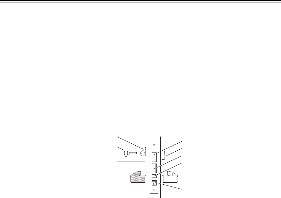
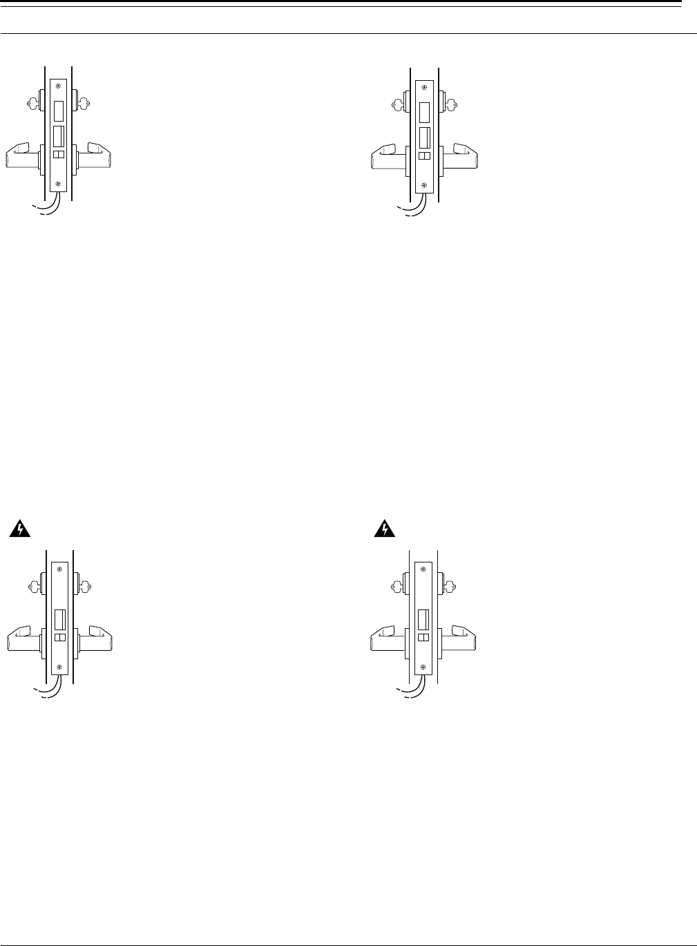
Figure 3.1 Understanding function drawings
Outside Inside
Shading indicates that
the lever is fixed.
Deadbolt
Thumb turn
Latchbolt
Auxiliary latch
Locking toggle
Emergency key
Keyed cylinder
Visual indicator
Lock Functions
40H Series Service Manual 3–5
Single-keyed
functions
The following lists describe how the latchbolt, deadbolt, outside lever,
and inside lever operate for each single-keyed 45H & 47H function.
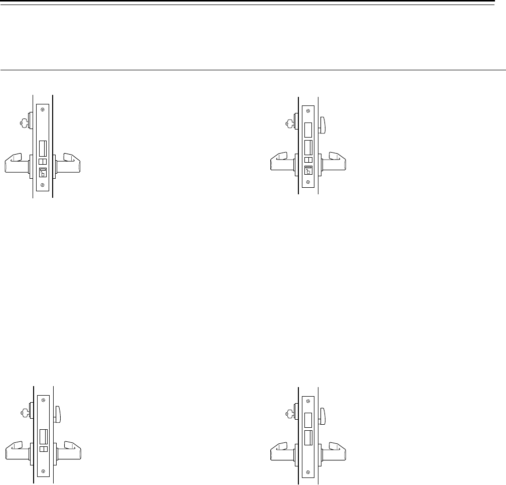
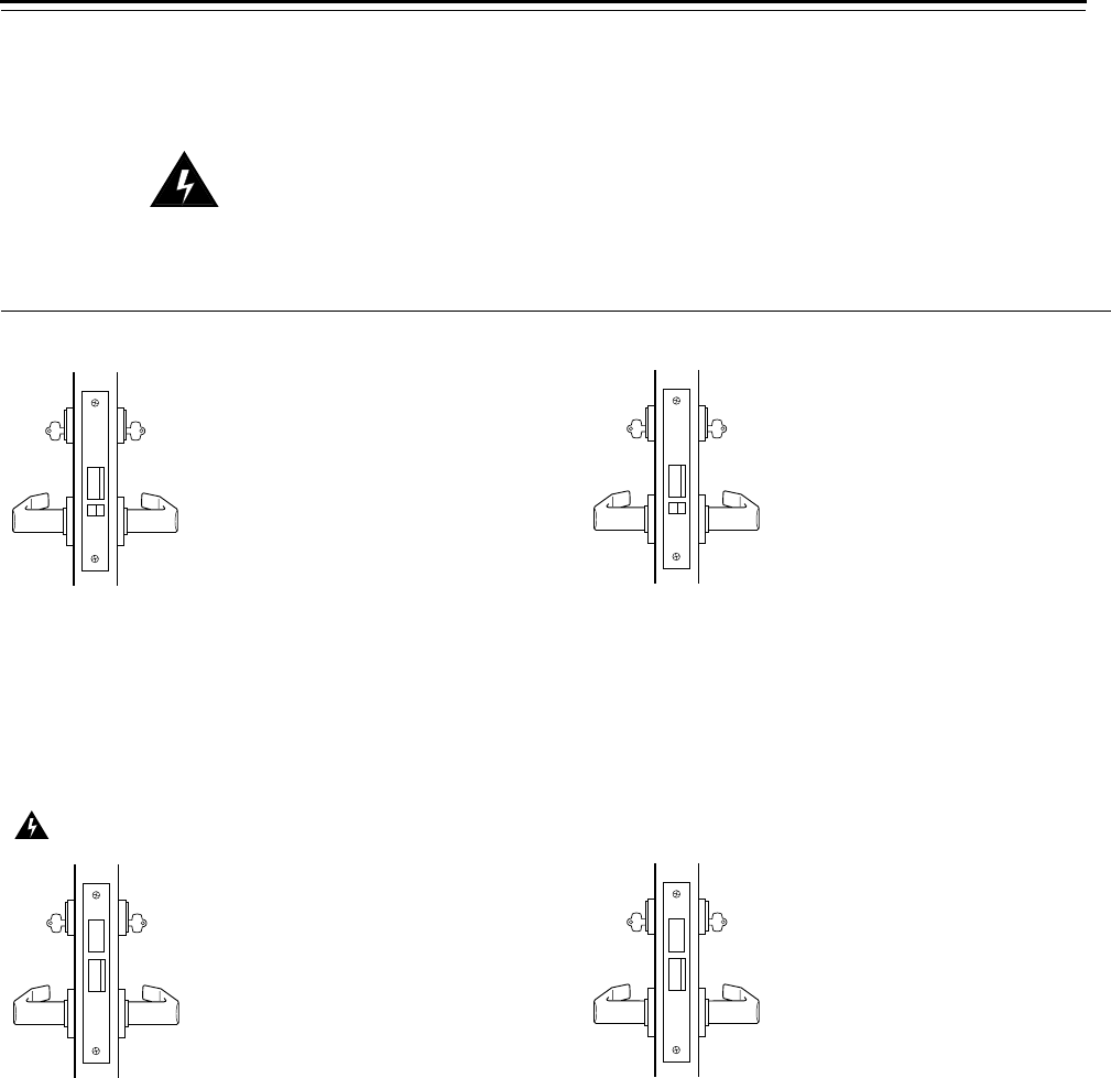
A–Office lock (ANSI F04) AB–Office lock (ANSI F20)
Latchbolt operated by:
■outside key
■outside lever when the locking
toggle is in the unlocked
position
■inside lever
Latchbolt is deadlocked by an
auxiliary latch
Outside lever locked by:
■placing the locking toggle in the
locked position
Outside lever unlocked by:
■placing the locking toggle in the
unlocked position
Inside lever is always unlocked
Latchbolt operated by:
■outside key
■outside lever when the locking
toggle is in the unlocked
position
■inside lever
Latchbolt is deadlocked by an
auxiliary latch
Deadbolt operated by:
■outside key
■inside thumb turn
■inside lever retracts the deadbolt
and latchbolt simultaneously
Outside lever locked by:
■placing the locking toggle in the
locked position
■extending the deadbolt
Outside lever unlocked by:
■placing the locking toggle in the
unlocked position
Inside lever is always unlocked
AT–Office lock (ANSI F04) B–Entrance lock (ANSI F21)
Latchbolt operated by:
■outside key
■outside lever when unlocked by
outside or thumb turn
■inside lever
Latchbolt is deadlocked by an
auxiliary latch
Outside lever locked by:
■outside key
■inside thumb turn
Outside lever unlocked by:
■outside key
■inside turn knob
Inside lever is always unlocked
Latchbolt operated by:
■outside key
■outside lever when the deadbolt
is retracted
■inside lever when the deadbolt is
retracted
Deadbolt operated by:
■outside key
■inside thumb turn
Inside and outside lever locked
by:
■extending the deadbolt
Lock Functions
3–6 40H Series Service Manual
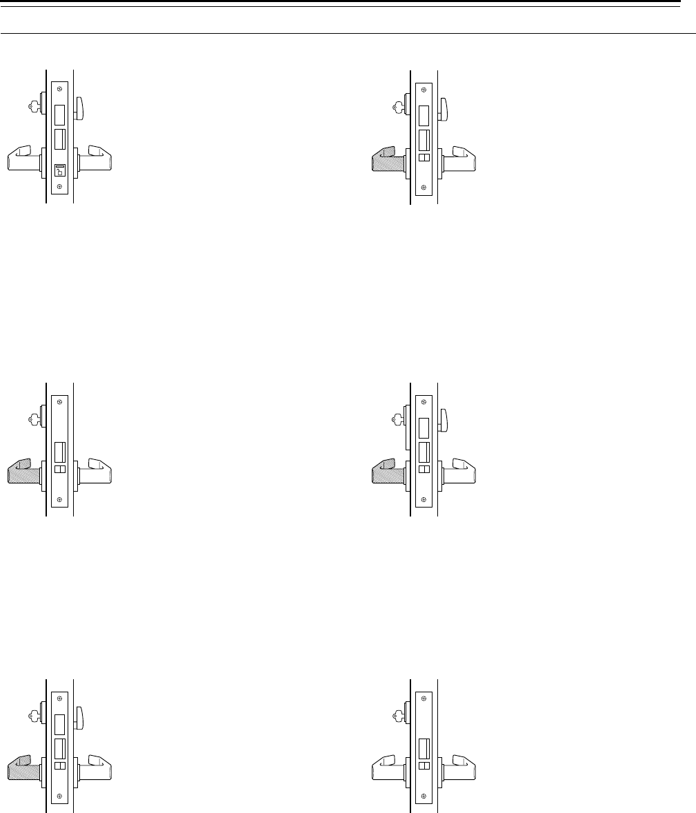
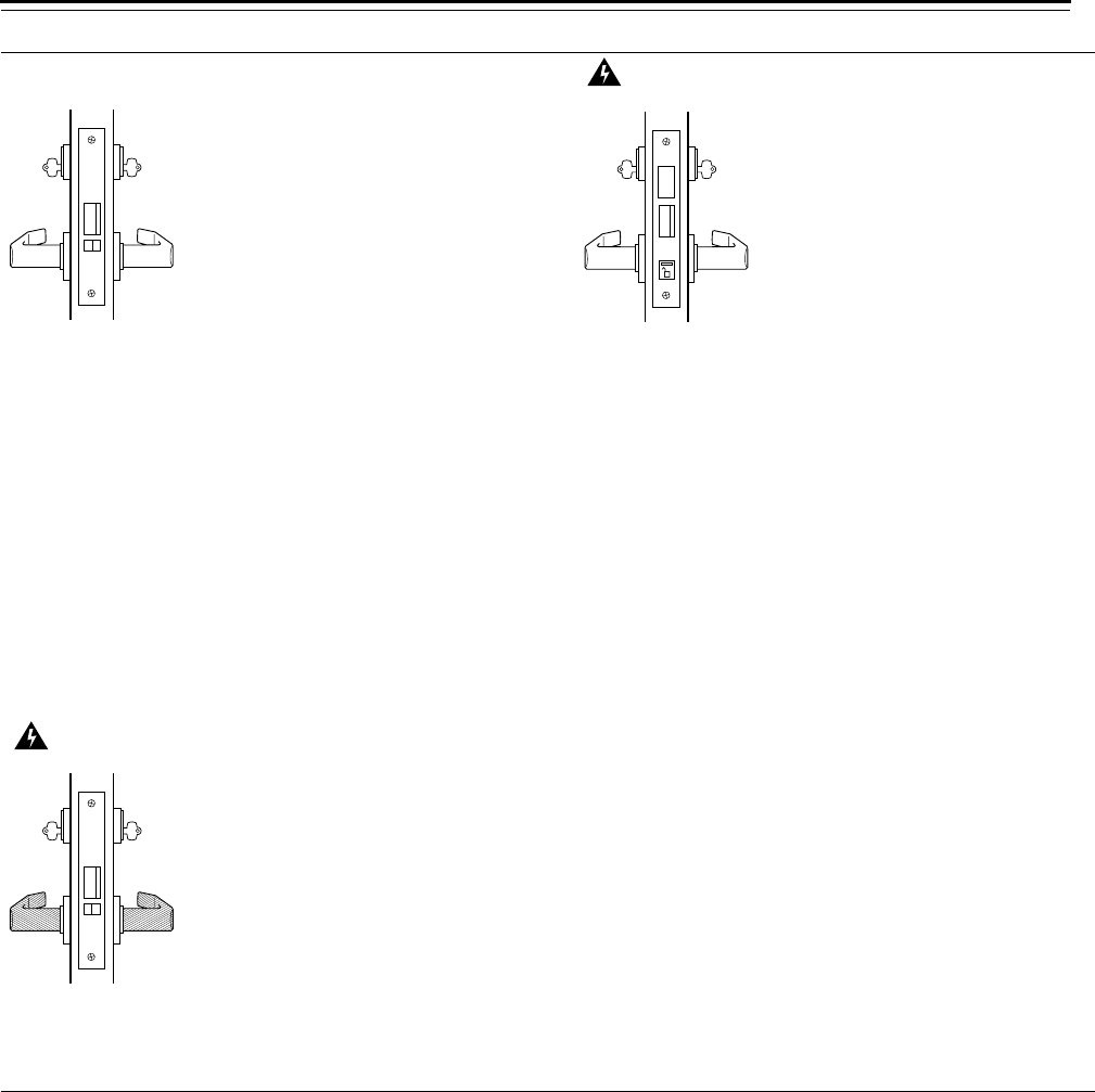
BA–Entrance lock (ANSI F08) BW–Entrance or storeroom lock
Latchbolt operated by:
■outside key
■outside lever when the locking
toggle is in the unlocked
position
■inside lever when the deadbolt is
retracted
Deadbolt operated by:
■outside key
■inside thumb turn
Outside lever locked by:
■extending the deadbolt
■placing the locking toggle in the
locked position
Inside lever locked by:
■extending the deadbolt
Latchbolt operated by:
■outside key
■inside lever when the deadbolt is
retracted
Latchbolt is deadlocked by an
auxiliary latch
Deadbolt operated by:
■outside key
■inside thumb turn
Outside lever is always fixed
Inside lever locked by:
■extending the deadbolt
D–Storeroom lock (ANSI F07) H–Hotel lock (ANSI F15)
Latchbolt operated by:
■outside key
■inside lever
Latchbolt is deadlocked by an
auxiliary latch
Outside lever is always fixed
Inside lever is always unlocked
Latchbolt operated by:
■outside key
■inside lever
Latchbolt is deadlocked by an
auxiliary latch
Deadbolt operated by:
■outside special master key
■inside thumb turn
■inside lever retracts the deadbolt
and latchbolt simultaneously
Outside lever is always fixed
Inside lever is always unlocked
Note 1: When the deadbolt is extended, the visual
indicator shows the locked icon.
Note 2: Available for 45H Locks only.
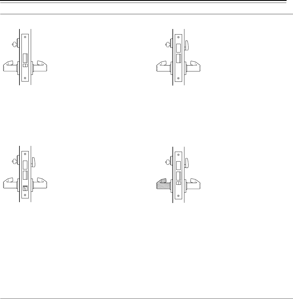
HJ–Hotel lock (ANSI F15) R–Classroom lock (ANSI F05)
Latchbolt operated by:
■outside key
■inside lever
Latchbolt is deadlocked by an
auxiliary latch
Deadbolt operated by:
■outside special master key
■inside thumb turn
■inside lever retracts the deadbolt
and latchbolt simultaneously
Outside lever is always fixed
Inside lever is always unlocked
Latchbolt operated by:
■outside key
■outside lever when unlocked by
the outside key
■inside lever
Latchbolt deadlocked by an
auxiliary latch
Outside lever locked and
unlocked by:
■outside key
Inside lever is always unlocked
Note: Available for 45H Locks only.
Lock Functions
40H Series Service Manual 3–7
RHB–Classroom holdback (ANSI F06) T–Dormitory lock (ANSI F13)
Latchbolt operated by:
■outside key/lever
■outside lever except when
locked by the outside key
■inside lever
Latchbolt is deadlocked by an
auxiliary latch
Latchbolt stays retracted after:
■turning the inside lever up and
then rotating the outside key
Outside lever locked and
unlocked by:
■outside key
Inside lever is always unlocked
Latchbolt operated by:
■outside lever when deadbolt is
retracted
■inside lever
Deadbolt operated by:
■outside key
■inside thumb turn
■inside lever retracts the deadbolt
and latchbolt simultaneously
Outside lever locked by:
■extending the deadbolt
Outside lever unlocked by:
■retracting the deadbolt
Inside lever is always unlocked
TA–Dormitory lock (ANSI F12) TD–Dormitory lock
Latchbolt operated by:
■outside key
■outside lever when the locking
toggle is in the unlocked
position and the deadbolt is
retracted
■inside lever
Deadbolt operated by:
■outside key
■inside thumb turn
■inside lever retracts the deadbolt
and latchbolt simultaneously
Outside lever locked by:
■placing the locking toggle in the
locked position
■extending the deadbolt
Outside lever unlocked by:
■outside key and placing the
locking toggle in the unlocked
position
Inside lever is always unlocked
Latchbolt operated by:
■outside key
■inside lever
Latchbolt is deadlocked by an
auxiliary latch
Deadbolt operated by:
■outside key
■inside thumb turn
■inside lever retracts the deadbolt
and latchbolt simultaneously
Outside lever is always fixed
Inside lever is always unlocked
Lock Functions
3–8 40H Series Service Manual
Double-keyed
functions
The following lists describe how the latchbolt, deadbolt, outside lever,
and inside lever operate for each double-keyed
45H & 47H function.
Warning!
Locks that secure both sides of the door are controlled by
building codes and the Life Safety Code®. In an emergency exit
situation, failure to quickly unlock the door could be hazardous,
or even fatal.
C–Public entrance (ANSI F09) CHB–Holdback
Latchbolt operated by:
■outside key
■outside lever except when
locked by inside key
■inside lever
Latchbolt is deadlocked by an
auxiliary latch
Outside lever locked and
unlocked by:
■inside key
Inside lever is always unlocked
Latchbolt operated by:
■outside key
■outside lever except when
locked by inside key
■inside lever
Latchbolt stays retracted after:
■turning the inside lever up and
then rotating the inside key
Latchbolt is deadlocked by an
auxiliary latch
Outside lever locked and
unlocked by:
■inside key
Inside lever is always unlocked
Note: The inside cylinder may be combinated to
operate by the master key only.
G–Communicating lock (ANSI F14) IND–Intruder lock (ANSI F33)
Latchbolt operated by:
■inside lever when deadbolt is
retracted
■outside lever when deadbolt is
retracted
Deadbolt operated by:
■outside key
■inside key
Outside lever locked by:
■extending the deadbolt
Inside lever locked and
unlocked by:
■inside key
■outside key
Latchbolt operated by:
■outside key
■inside key
■outside lever when deadbolt is
retracted
■inside lever
Deadbolt operated by:
■outside key
■inside key
■inside lever retracts the deadbolt
and latchbolt simultaneously
Outside lever locked by:
■extending the deadbolt
Outside lever unlocked by:
■retracting the deadbolt
Inside lever is always unlocked
Lock Functions
40H Series Service Manual 3–9
INL–Intruder lock (ANSI F32) S–Storeroom lock (ANSI F35)
Latchbolt operated by:
■outside and inside key
■outside lever when not locked
by inside or outside key
■inside lever
Latchbolt is deadlocked by an
auxiliary latch
Outside lever locked and
unlocked by:
■outside key and inside key
Inside lever is always unlocked
Latchbolt operated by:
■outside and inside key
■outside lever when the locking
toggle is in the unlocked
position
■inside lever when the deadbolt is
retracted
Deadbolt operated by:
■outside key
■inside key
Outside lever locked by:
■placing the locking toggle in the
locked position
Outside lever unlocked by:
■retracting the deadbolt and
placing the locking toggle in the
unlocked position
Inside lever locked by:
■extending the deadbolt
Inside lever unlocked by:
■retracting the deadbolt
W–Storeroom lock (ANSI F30)
Latchbolt operated by:
■inside key
■outside key
Latchbolt is deadlocked by an
auxiliary latch
Outside lever is always fixed
Inside lever is always fixed
Note: When required, the inside cylinder may be
combinated to operate by master key only.
Lock Functions
3–10 40H Series Service Manual
Deadlocked
functions
The following lists describe how the deadbolt operates for each
deadlocked 45H & 47H function.
Warning!
Locks that secure both sides of the door are controlled by
building codes and the Life Safety Code®. In an emergency exit
situation, failure to quickly unlock the door could be hazardous,
or event fatal.
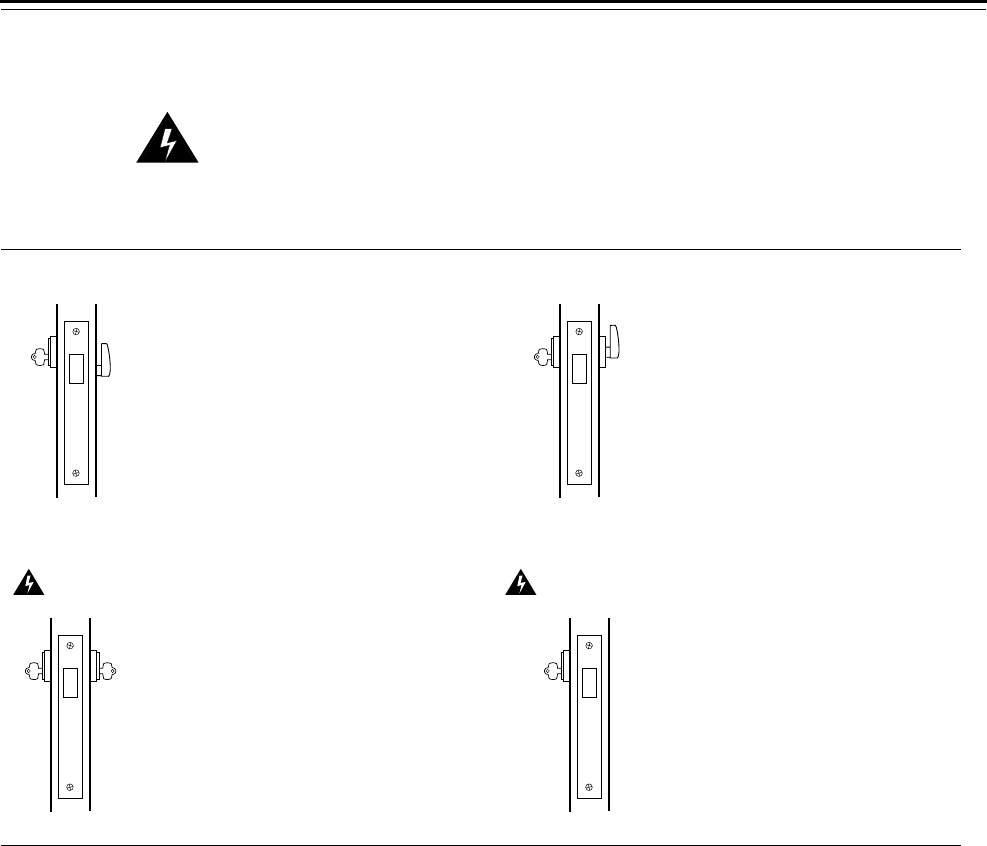
AD–Deadlock (ANSI F17) RD–Classroom deadlock (ANSI F29)
Deadbolt extended by:
■outside key
Deadbolt retracted by:
■inside thumb turn
Deadbolt extended by:
■outside key
Deadbolt retracted by:
■outside key
■inside thumb turn
Note: Specify the hand of the door.
WD–Deadlock (ANSI F16) YD–Deadlock (ANSI F18)
Deadbolt operated by:
■outside key
■inside key
Deadbolt operated by:
■outside key
Lock Functions
40H Series Service Manual 3–11
Non-keyed
functions
The following lists describe how the latchbolt, deadbolt, outside lever,
and inside lever operate for each non-keyed 45H function.
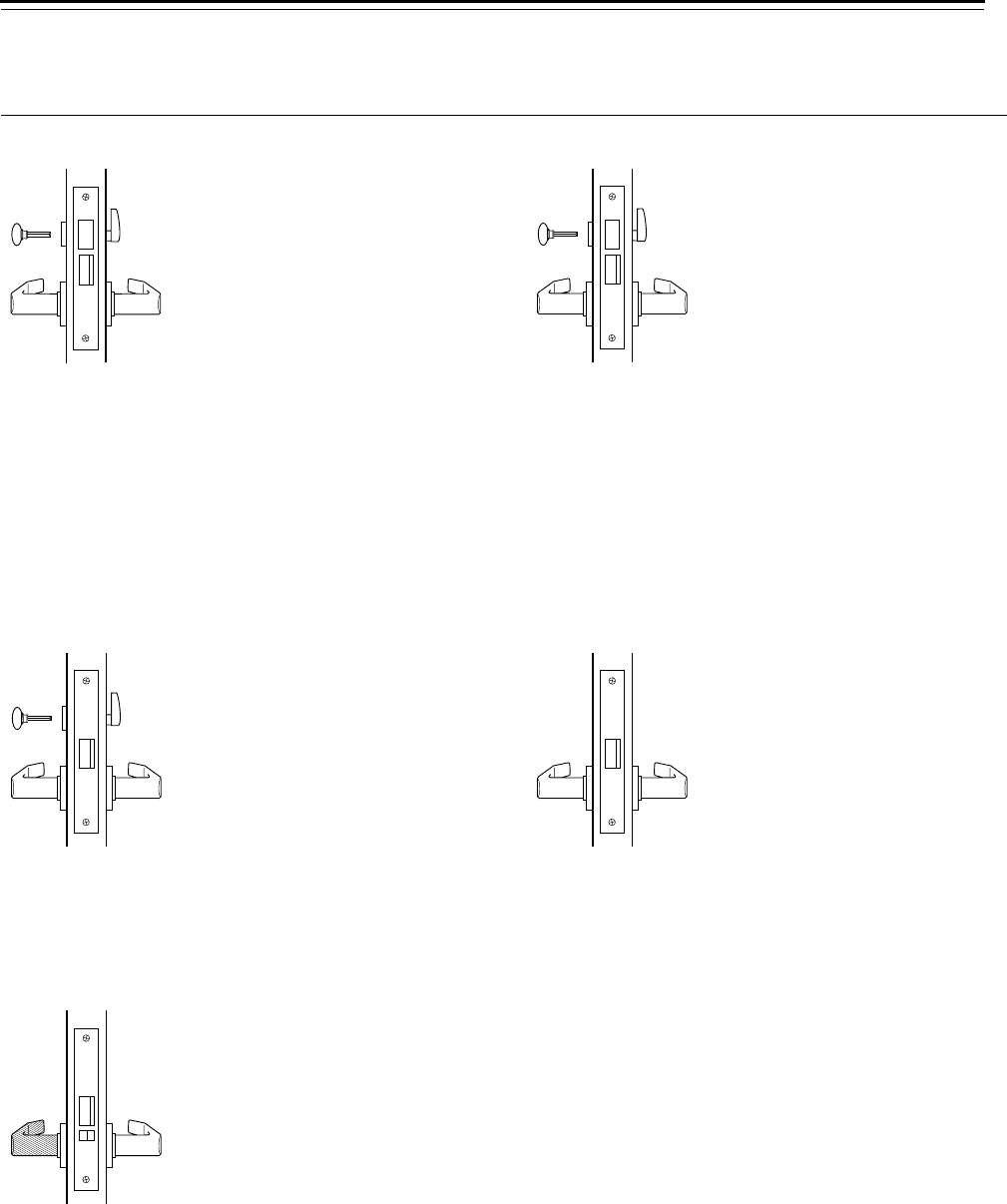
L–Privacy lock (ANSI F19) LB–Privacy lock (ANSI F02)
Latchbolt operated by:
■outside lever when the deadbolt
is retracted
■inside lever
Deadbolt operated by:
■outside emergency key
■inside thumb turn
■inside lever retracts the deadbolt
and latchbolt simultaneously
Outside lever locked by:
■outside emergency key
■inside thumb turn
Outside lever unlocked by:
■outside emergency key
■inside thumb turn
■inside lever
Inside lever is always unlocked
Latchbolt operated by:
■outside lever when the deadbolt
is retracted
■inside lever when the deadbolt is
retracted
Deadbolt operated by:
■outside emergency key
■inside thumb turn
Inside and outside lever locked
by:
■extending the deadbolt
Inside and outside lever
unlocked by:
■retracting the deadbolt
LT–Privacy lock N–Passage lock (ANSI F01)
Latchbolt operated by:
■outside lever when thumb turn is
unlocked
■inside lever
Outside lever locked by:
■outside emergency key
■inside thumb turn
Outside lever unlocked by:
■outside emergency key
■inside thumb turn
■inside lever
Inside lever is always unlocked
Latchbolt operated by:
■outside lever
■inside lever
Inside and outside levers are
always unlocked
NX–Exit lock (ANSI F31)
Latchbolt operated by:
■inside lever
Latchbolt is deadlocked by an
auxiliary latch
Outside lever is always fixed
Inside lever is always unlocked
Lock Functions
3–12 40H Series Service Manual
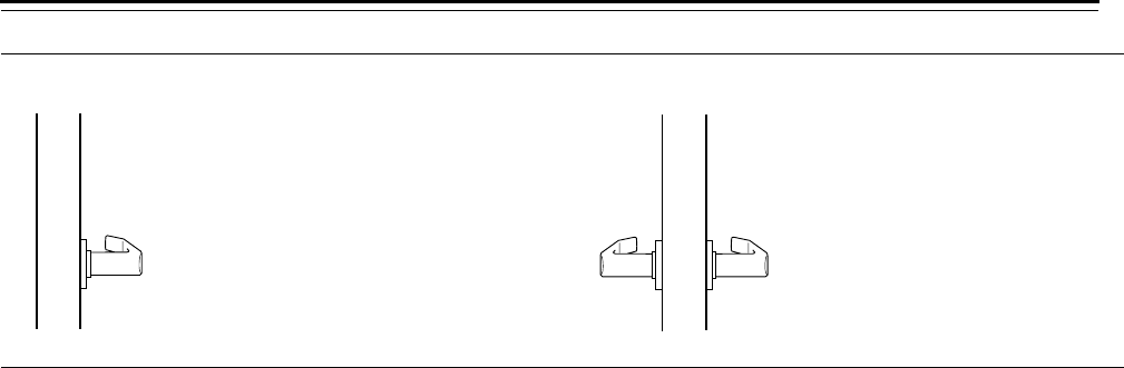
1DT–Single dummy trim 2DT–Double dummy trim
This product is a single, surface
mounted lever for an inactive door
or a non-latching door.
This product is a through-bolt
mounted pair of matching levers
for an inactive door or a
non-latching door.
Lock Functions
40H Series Service Manual 3–13
Special
functions
The following lists describe how the latchbolt, deadbolt, outside lever,
and inside lever operate for each special 45H & 47H function.
Warning!
Locks that secure both sides of the door are controlled by
building codes and the Life Safety Code®. In an emergency exit
situation, failure to quickly unlock the door could be hazardous,
or even fatal.
B5–Entrance lock B7–Entrance lock
Latchbolt operated by:
■outside key
■outside lever when the deadbolt
is retracted
■inside lever when the deadbolt is
retracted
Deadbolt operated by:
■outside key
Inside and outside lever locked
by:
■extending the deadbolt
Latchbolt operated by:
■inside key
■outside key
■outside lever when the deadbolt
is retracted
■inside lever when the deadbolt is
retracted
Deadbolt operated by:
■outside key
■inside key
Inside and outside lever locked
by:
■extending the deadbolt
Note 1: Trim is removable from the outside only.
Note 2: The only difference between the 35H–37H B4
and B5 functions was the cylinder retaining screw. The
B4 and B5 functions have been combined into the
45H & 47H B5 function.
Note 1: Trim is removable from the outside only.
Note 2: The only difference between the 35H–37H B6
and B7 functions was the cylinder retaining screw. The
B6 and B7 functions have been combined into the
45H & 47H B7 function.
XR–Classroom lock ZD–Storeroom lock
Latchbolt operated by:
■outside key
■inside lever
Inside lever is always unlocked
Latchbolt operated by:
■outside key
Latchbolt is deadlocked by an
auxiliary latch
Outside lever is always locked
Lock Functions
3–14 40H Series Service Manual
Electrified
functions
The following lists describe how the latchbolt, deadbolt, outside lever,
and inside lever operate for each electrified 45HW & 47HW function.
Warning!
Locks that secure both sides of the door are controlled by
building codes and the Life Safety Code®. In an emergency exit
situation, failure to quickly unlock the door could be hazardous,
or even fatal.
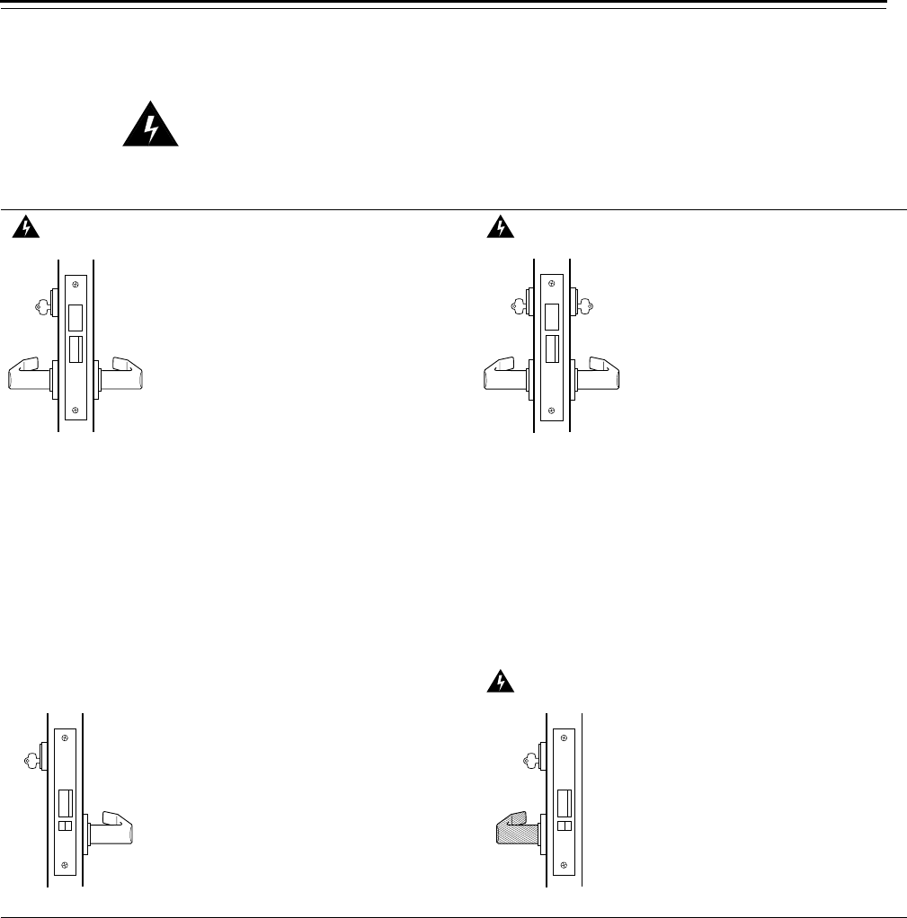
DEL–Electrically locked–Fail safe lock DEU–Electrically unlocked–Fail secure lock
Latchbolt operated by:
■outside lever when power is
removed from the solenoid
■outside key
■inside lever
Latchbolt is deadlocked by an
auxiliary latch
Outside lever locked by:
■applying power to solenoid;
remains locked while power is
continuously applied
Outside lever unlocked by:
■removing power from the
solenoid
Inside lever is always unlocked
Latchbolt operated by:
■outside lever when power is
applied to the solenoid
■outside key
■inside lever
Latchbolt is deadlocked by an
auxiliary latch
Outside lever locked by:
■removing power from solenoid
Outside lever unlocked by:
■applying power to the solenoid;
remains unlocked while power is
continuously applied
Inside lever is always unlocked
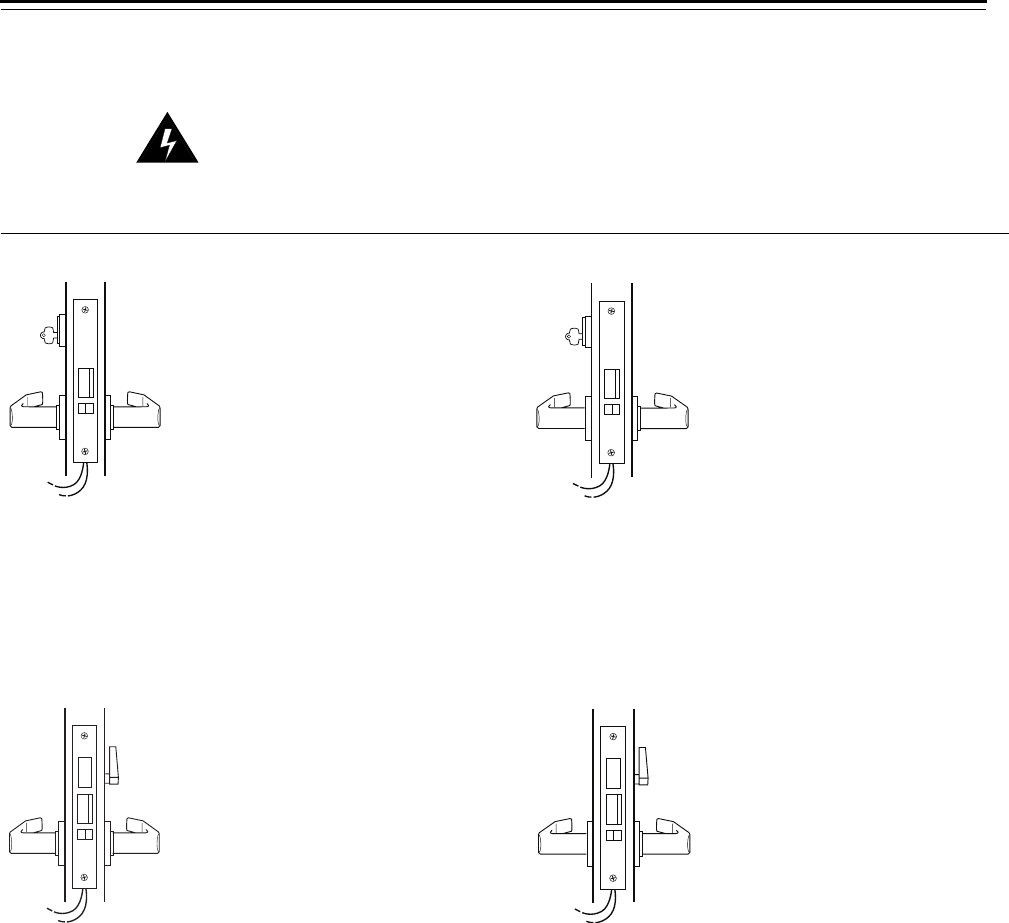
LEL–Electrically locked–Fail safe lock LEU–Electrically unlocked–Fail secure lock
Latchbolt operated by:
■outside lever when power is
removed from the solenoid
■inside lever
Latchbolt is deadlocked by an
auxiliary latch
Deadbolt extended by:
■inside thumb turn
Deadbolt retracted by:
■inside thumb turn
■inside lever retracts the deadbolt
and latchbolt simultaneously
■outside lever when power is
removed
Outside lever locked by:
■applying power to the solenoid;
remains locked while power is
continuously applied
Outside lever unlocked by:
■removing power from the
solenoid
Inside lever is always unlocked
Latchbolt operated by:
■outside lever when power is
applied to the solenoid
■inside lever
Latchbolt is deadlocked by an
auxiliary latch
Deadbolt extended by:
■inside thumb turn
Deadbolt retracted by:
■inside thumb turn
■inside lever retracts the deadbolt
and latchbolt simultaneously
■outside lever when power is
applied
Outside lever locked by:
■removing power from the
solenoid
Outside lever unlocked by:
■applying power to the solenoid;
remains unlocked while power is
continuously applied
Inside lever is always unlocked
Lock Functions
40H Series Service Manual 3–15
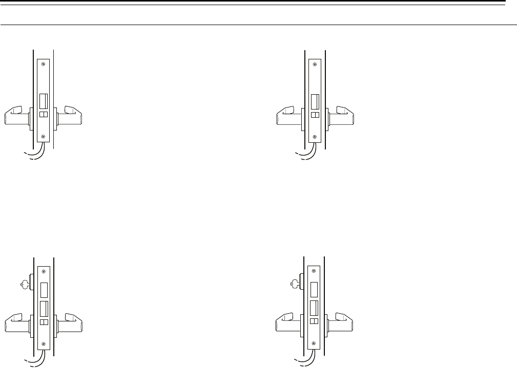
NXEL–Electrically locked–Fail safe lock NXEU–Electrically unlocked–Fail secure lock
Latchbolt operated by:
■outside lever when power is
removed from the solenoid
■inside lever
Latchbolt is deadlocked by an
auxiliary latch
Outside lever locked by:
■applying power to the solenoid;
remains locked while power is
continuously applied
Outside lever unlocked by:
■removing power from the
solenoid
Inside lever is always unlocked
Latchbolt operated by:
■outside lever when power is
applied to the solenoid
■inside lever
Latchbolt is deadlocked by an
auxiliary latch
Outside lever locked by:
■removing power from the
solenoid
Outside lever unlocked by:
■applying power to the solenoid;
remains unlocked while power is
continuously applied
Inside lever is always unlocked
TDEL–Electrically locked–Fail safe lock TDEU–Electrically unlocked–Fail secure lock)
Latchbolt operated by:
■outside key
■outside lever when power is
removed from the solenoid
Latchbolt is deadlocked by an
auxiliary latch
Deadbolt operated by:
■outside key
Outside lever locked by:
■applying power to the solenoid;
remains locked while power is
continuously applied
Outside lever unlocked by:
■removing power from the
solenoid
Inside lever is always unlocked
Deadbolt and latchbolt
retracted simultaneously by:
■inside lever
■outside lever when power is
removed
Latchbolt operated by:
■outside key
■outside lever when power is
applied to the solenoid
Latchbolt is deadlocked by an
auxiliary latch
Deadbolt operated by:
■outside key
Outside lever locked by:
■removing power from the
solenoid
Outside lever unlocked by:
■applying power to the solenoid;
remains unlocked while power is
continuously applied
Inside lever is always unlocked
Deadbolt and latchbolt
retracted simultaneously by:
■inside lever
■outside lever when power is
applied
Lock Functions
3–16 40H Series Service Manual
TWEL–Electrically locked–Fail safe lock TWEU–Electrically unlocked–Fail secure lock
Latchbolt operated by:
■outside and inside key
■outside and inside lever when
power is removed from the
solenoid
Latchbolt is deadlocked by an
auxiliary latch
Deadbolt operated by:
■outside key
■inside key
■outside and inside lever when
power is removed from the
solenoid
Outside lever locked by:
■applying power to the solenoid;
remains locked while power is
continuously applied
Outside lever unlocked by:
■removing power from the
solenoid
Inside lever locked by:
■applying power to the solenoid;
remains locked while power is
continuously applied
Inside lever unlocked by:
■removing power from solenoid
Latchbolt operated by:
■outside and inside key
■outside and inside lever when
power is applied to the solenoid
Latchbolt is deadlocked by an
auxiliary latch
Deadbolt operated by:
■outside key
■inside key
■outside and inside lever when
power is applied to the solenoid
Outside lever locked by:
■removing power from the
solenoid
Outside lever unlocked by:
■applying power to the solenoid;
remains unlocked while power is
continuously applied
Inside lever locked by:
■removing power from the
solenoid
Inside lever unlocked by:
■applying power to the solenoid;
remains locked while power is
continuously applied
WEL–Electrically locked–Fail safe lock WEU–Electrically unlocked–Fail secure lock
Latchbolt operated by:
■inside lever when power is
removed from the solenoid
■outside lever when power is
removed from the solenoid
■inside key
■outside key
Latchbolt is deadlocked by an
auxiliary latch
Outside lever locked by:
■applying power to the solenoid;
remains locked while power is
continuously applied
Outside lever unlocked by:
■removing power from the
solenoid
Inside lever locked by:
■applying power to the solenoid;
remains locked while power is
continuously applied
Inside lever unlocked by:
■removing power from the
solenoid
Latchbolt operated by:
■inside lever when power is
applied to the solenoid
■outside lever when power is
applied to the solenoid
■inside key
■outside key
Latchbolt is deadlocked by an
auxiliary latch
Outside lever locked by:
■removing power from the
solenoid
Outside lever unlocked by:
■applying power to the solenoid;
remains locked while power is
continuously applied
Inside lever locked by:
■removing power from the
solenoid
Inside lever unlocked by:
■applying power to the solenoid;
remains locked while power is
continuously applied

40H Series Service Manual 4–1
4 MORTISE CASE PARTS
The following pages contain exploded diagrams and
parts lists for 45H & 47H and 45HW & 47HW mortise
cases. Use the table below to find the page number
for a particular function. For exploded diagrams and
parts lists for 48H mortise cases, see 48H &
49H Mortise case parts on page 7–2.
For this
function See page
For this
function See page
For this
function See page
A4–2 H4–24 S4–18
AB 4–14 HJ 4–24 T4–26
AD 4–34 IND 4–26 TA 4–32
AT 4–4 INL 4–4 TD 4–24
B4–16 L4–28 TDEL 4–50
BA 4–18 LB 4–30 TDEU 4–52
BW 4–20 LEL 4–58 TWEL 4–54
B5 4–22 LEU 4–60 TWEU 4–56
B7 4–22 LT 4–6 W4–4
C4–4 NX 4–10 WEL 4–42
CHB 4–12 NXEL 4–46 WEU 4–44
D4–4 NXEU 4–48 WD 4–34
DEL 4–38 R4–4 XR 4–4
DEU 4–40 RD 4–36 YD 4–34
G4–22 RHB 4–12 ZD 4–4
Mortise Case Parts
4–2 40H Series Service Manual
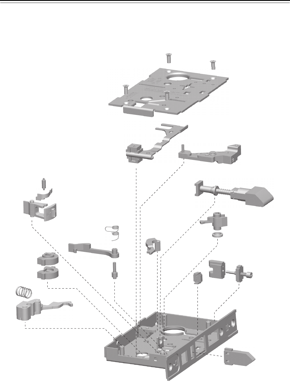
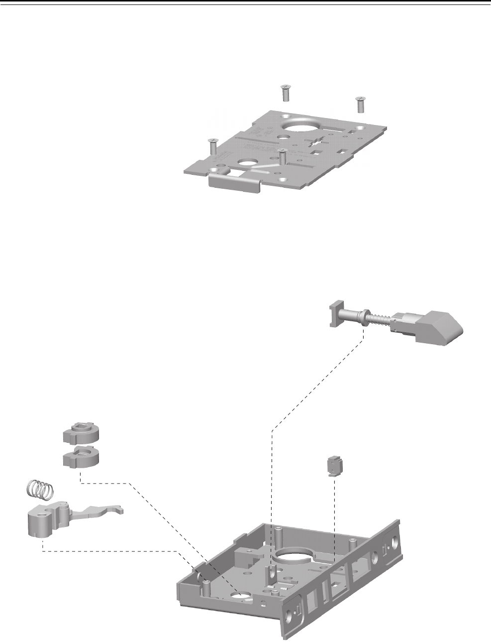
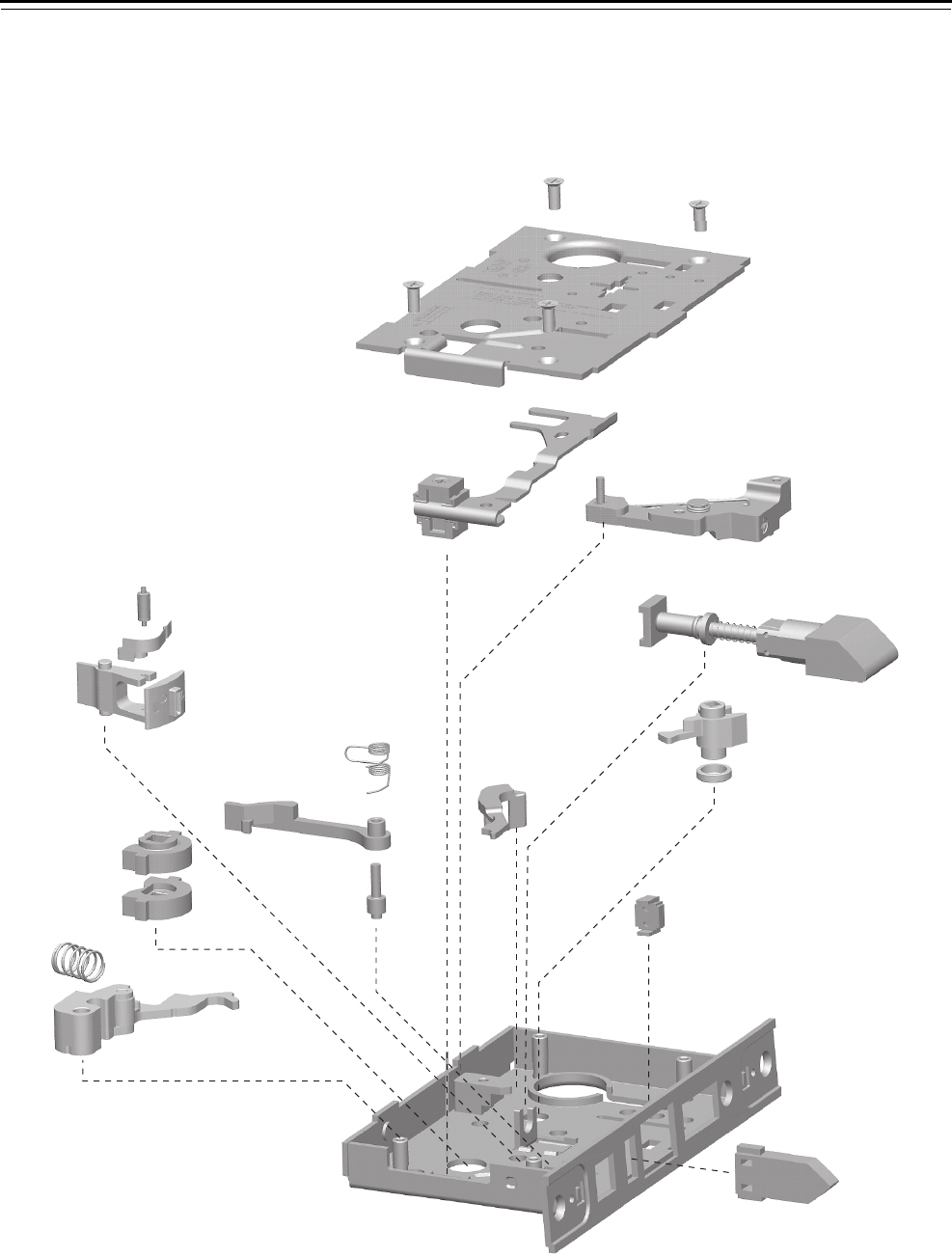
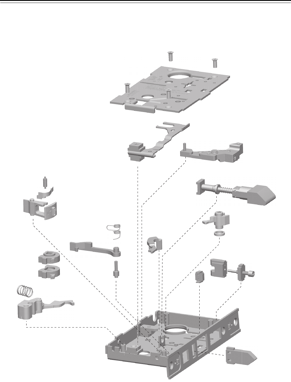
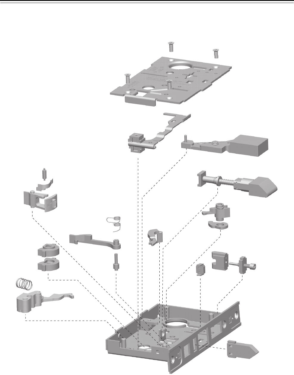
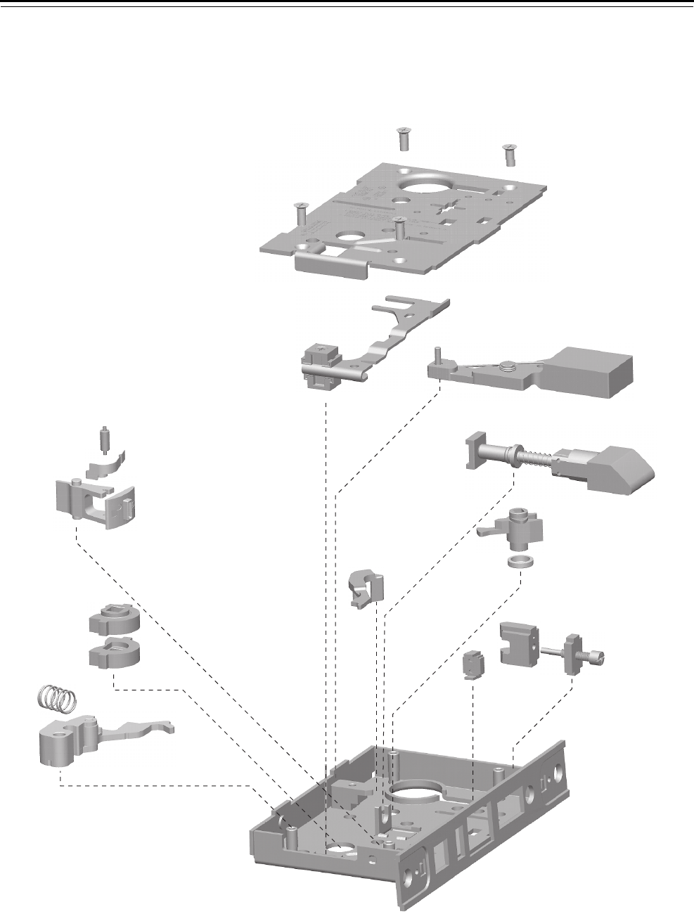
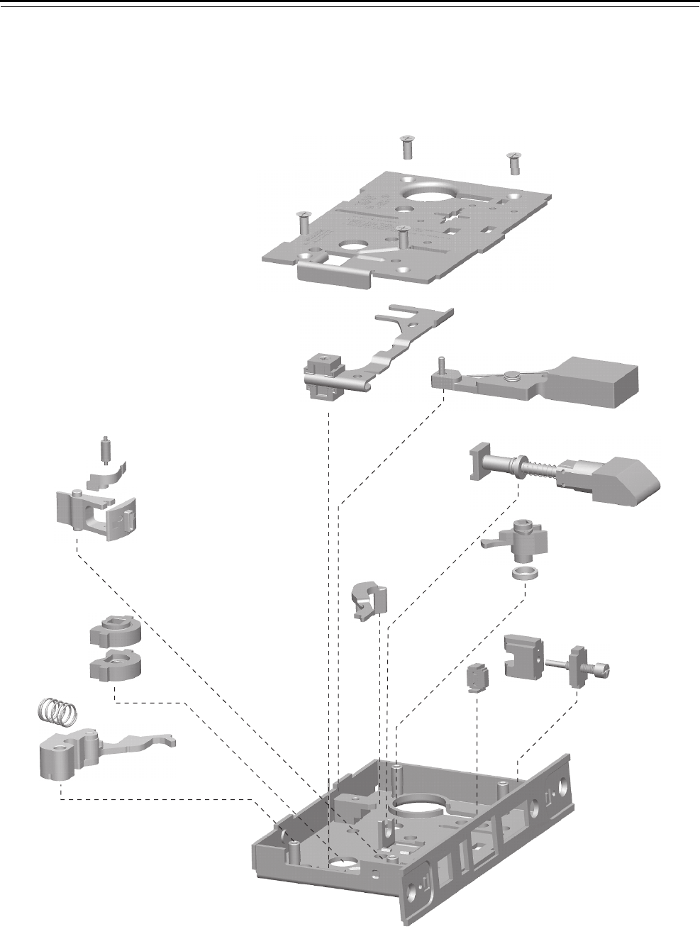
AFUNCTION CASE—OFFICE LOCK
Figure 4.1 A function case exploded diagram
1
2
3
4
5
6
7
8
9
10
11
13
14
15
16
17
18
12
19
20
21
22

Mortise Case Parts
40H Series Service Manual 4–3
A function case
parts list
Refer to Figure 4.1 and the table below to find the part you need.
Item Part No.a
a. For a complete case, use C45504. To order a “case only” lock, which includes a
mortise case, faceplate, and strike, see page 4–62.
Qty. Description
1 A34087 4 Case cover mounting screw
2 D44010 1 Cover
3 C45030 1 Locking lever and toggle assembly
4 B45040 1 Key release shuttle assembly
5 B45020 1 Latchbolt sub-assembly
6 C44108 1 Turn knob hub (lost motion)
7 A34120 1 Turn knob hub spacer
8 C44110 1 Key release lever
9 C44144 1 Cylinder retainer
10 B45090 1 Cylinder retainer assembly
11 B44166 1 Fusible link molded assembly
12 C44142 1 Auxiliary bolt
13 A44188 1 Toggle roller
14 B44190 1 Toggle lever spring
15 C44100 1 Toggle lever
16 B44194 1 Deadlocking lever spring
17 C44148 1 Deadlocking lever
18 A44184 1 Deadlocking lever pin
19 C44146 2 Hub
20 A44193 1 Release lever spring
21 C45010 1 Release lever sub-assembly
22 C45000 1 Case sub-assembly
Mortise Case Parts
4–4 40H Series Service Manual
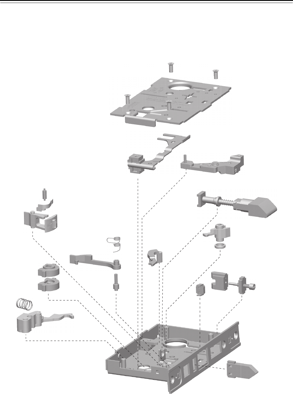
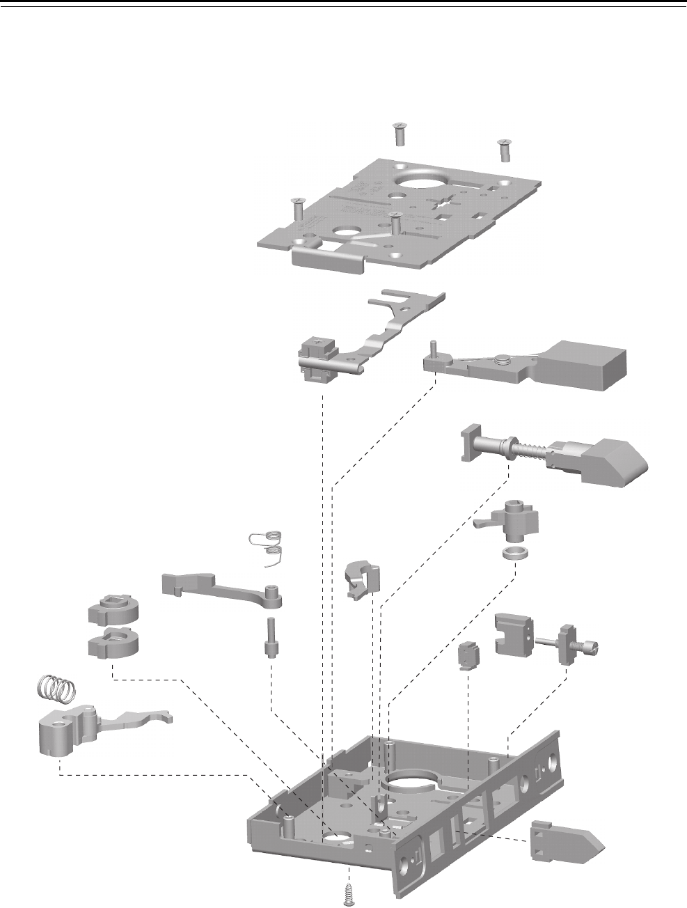
AT FUNCTION CASE—OFFICE LOCK RFUNCTION CASE—CLASSROOM LOCK
CFUNCTION CASE—PUBLIC ENTRANCE LOCK WFUNCTION CASE—STOREROOM LOCK
DFUNCTION CASE—STOREROOM LOCK ZD FUNCTION CASE—STOREROOM LOCK
INL FUNCTION CASE—INTRUDER LOCK XR FUNCTION CASE—CLASSROOM LOCK
Figure 4.2 AT, C, D, INL, R, W, ZD, XR function case exploded diagram
1
2
3
4
5
6
7
8
9
10
11
13
14
15
16
17
18
12
19
20
21
22

Mortise Case Parts
40H Series Service Manual 4–5
AT, C, D, INL, R, W,
ZD, XR function
case parts list
Refer to Figure 4.2 and the table below to find the part you need.
Item Part No.a
a. For a complete case assembly, use C45507 and reconfigure the shuttle screws as
needed. See Changing the function for universal cases on page 6-5. To order a
“case only” lock, which includes a mortise case, faceplate, and strike, see page 4–62.
Qty. Description
1 A34087 4 Case cover mounting screw
2 D44010 1 Cover
3 C45030 1 Locking lever and toggle assembly
4 B45040 1 Key release shuttle assembly
5 B45020 1 Latchbolt sub-assembly
6 C44106 1 Turn knob hub (non-deadbolt)
7 A34120 1 Turn knob hub spacer
8 C44110 1 Key release lever
9 C44144 1 Cylinder retainer
10 B45090 1 Cylinder retainer assembly
11 B44166 1 Fusible link molded assembly
12 C44142 1 Auxiliary bolt
13 A44188 1 Toggle roller
14 B44190 1 Toggle lever spring
15 C44100 1 Toggle lever
16 B44194 1 Deadlocking lever spring
17 C44148 1 Deadlocking lever
18 A44184 1 Deadlocking lever pin
19 C44146 2 Hub
20 A44193 1 Release lever spring
21 C45010 1 Release lever sub-assembly
22 C45000 1 Case sub-assembly
Mortise Case Parts
4–6 40H Series Service Manual
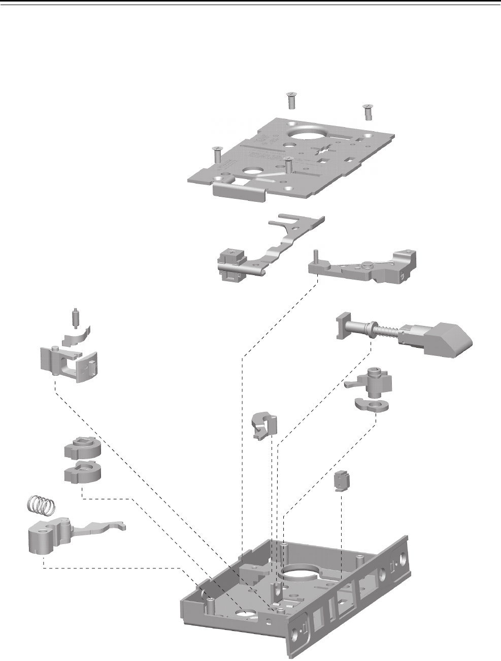
LT FUNCTION CASE—PRIVACY LOCK
Figure 4.3 LT function case exploded diagram
1
2
3
4
5
6
7
8
9
10
11
12
13
14
15
16

Mortise Case Parts
40H Series Service Manual 4–7
LT function case
parts list
Refer to Figure 4.3 and the table below to find the part you need.
Item Part No.a
a. For a complete case, use C45520. To order a “case only” lock, which includes a
mortise case, faceplate, and strike, see page 4–62.
Qty. Description
1 A34087 4 Case cover mounting screw
2 D44010 1 Cover
3 C45030 1 Locking lever and toggle assembly
4 B45040 1 Key release shuttle assembly
5 B45020 1 Latchbolt sub-assembly
6 C44104 1 Turn knob hub (deadbolt)
7 A34032 1 Turn knob hub cam
8 C44110 1 Key release lever
9 B44166 1 Fusible link molded assembly
10 A44188 1 Toggle roller
11 B44190 1 Toggle lever spring
12 C44100 1 Toggle lever
13 C44146 2 Hub
14 A44193 1 Release lever spring
15 C45010 1 Release lever sub-assembly
16 C45000 1 Case sub-assembly
Mortise Case Parts
4–8 40H Series Service Manual
NFUNCTION CASE—PASSAGE LOCK
Figure 4.4 N function case exploded diagram
1
2
3
4
5
6
7
8

Mortise Case Parts
40H Series Service Manual 4–9
N function case
parts list
Refer to Figure 4.4 and the table below to find the part you need.
Item Part No.a
a. For a complete case, use C45505. To order a “case only” lock, which includes a
mortise case, faceplate, and strike, see page 4–62.
Qty. Description
1 A34087 4 Case cover mounting screw
2 D44010 1 Cover
3 B45020 1 Latchbolt sub-assembly
4 B44166 1 Fusible link molded assembly
5 C44146 2 Hub
6 A44193 1 Release lever spring
7 C45010 1 Release lever sub-assembly
8 C45000 1 Case sub-assembly
Mortise Case Parts
4–10 40H Series Service Manual
NX FUNCTION CASE—EXIT LOCK
Figure 4.5 NX function case exploded diagram
1
2
3
4
5
6
7
8
9
11
12
13
14
15
16
17
18
19
20
10

Mortise Case Parts
40H Series Service Manual 4–11
NX function case
parts list
Refer to Figure 4.5 and the table below to find the part you need.
Item Part No.a
a. For a complete case, use C45506. To order a “case only” lock, which includes a
mortise case, faceplate, and strike, see page 4–62.
Qty. Description
1 A34087 4 Case cover mounting screw
2 D44010 1 Cover
3 C45030 1 Locking lever and toggle assembly
4 B45040 1 Key release shuttle assembly
5 B45020 1 Latchbolt sub-assembly
6 C44106 1 Turn knob hub (non-deadbolt)
7 A34120 1 Turn knob hub spacer
8 C44110 1 Key release lever
9 B44166 1 Fusible link molded assembly
10 C44142 1 Auxiliary bolt
11 A44188 1 Toggle roller
12 B44190 1 Toggle lever spring
13 C44100 1 Toggle lever
14 B44194 1 Deadlocking lever spring
15 C44148 1 Deadlocking lever
16 A44184 1 Deadlocking lever pin
17 C44146 2 Hub
18 A44193 1 Release lever spring
19 C45010 1 Release lever sub-assembly
20 C45000 1 Case sub-assembly
Mortise Case Parts
4–12 40H Series Service Manual
CHB FUNCTION CASE—HOLDBACK LOCK
RHB FUNCTION CASE—CLASSROOM HOLDBACK LOCK
Figure 4.6 CHB, RHB function case exploded diagram
1
2
4
5
6
7
8
8
10
11
12
14
15
16
17
18
19
13
21
22
23
24
20
3

Mortise Case Parts
40H Series Service Manual 4–13
CHB, RHB function
case parts list
Refer to Figure 4.6 and the table below to find the part you need
Item Part No.a
a. For a complete case, use C45523. To order a “case only” lock, which includes a
mortise case, faceplate, and strike, see page 4–62.
Qty. Description
1 A34087 4 Case cover mounting screw
2 C44537 1 Holdback cover
3 B44535 2 Holdback locking toggle
4 C44054 1 Locking lever
5 B45040 1 Key release shuttle assembly
6 B45020 1 Latchbolt sub-assembly
7 C44106 1 Turn knob hub (non-deadbolt)
8 A34120 1 Turn knob hub spacer
9 C44110 1 Key release lever
10 C44144 1 Cylinder retainer
11 B45090 1 Cylinder retainer assembly
12 B44166 1 Fusible link molded assembly
13 C44142 1 Auxiliary bolt
14 A44188 1 Toggle roller
15 B44190 1 Toggle lever spring
16 C44100 1 Toggle lever
17 B44194 1 Deadlocking lever spring
18 C44148 1 Deadlocking lever
19 A44184 1 Deadlocking lever pin
20 C44532 1 Holdback hub LH
21 C44533 1 Holdback hub RH
22 A44193 1 Release lever spring
23 C45010 1 Release lever sub-assembly
24 C45002 1 Holdback case sub-assembly
Mortise Case Parts
4–14 40H Series Service Manual
AB FUNCTION CASE—OFFICE LOCK
Figure 4.7 AB function case exploded diagram
1
2
3
4
5
6
7
8
9
10
11
13
14
15
16
17
18
12
19
20
21
22

Mortise Case Parts
40H Series Service Manual 4–15
AB function case
parts list
Refer to Figure 4.7 and the table below to find the part you need.
Item Part No.a
a. For a complete case, use C45502. To order a “case only” lock, which includes a
mortise case, faceplate, and strike, see page 4–62.
Qty. Description
1 A34087 4 Case cover mounting screw
2 D44010 1 Cover
3 C45032 1 “F” locking lever sub-assembly
4 B45060 1 Deadbolt sub-assembly
5 B45020 1 Latchbolt sub-assembly
6 C44104 1 Turn knob hub (deadbolt)
7 B34032 1 Turn knob hub cam
8 C44110 1 Key release lever
9 C44144 1 Cylinder retainer
10 B45090 1 Cylinder retainer assembly
11 B44166 1 Fusible link molded assembly
12 C44142 1 Auxiliary bolt
13 A44188 1 Toggle roller
14 B44190 1 Toggle lever spring
15 C44100 1 Toggle lever
16 B44194 1 Deadlocking lever spring
17 C44148 1 Deadlocking lever
18 A44184 1 Deadlocking lever pin
19 C44146 2 Hub
20 A44193 1 Release lever spring
21 C45010 1 Release lever sub-assembly
22 C45000 1 Case sub-assembly
Mortise Case Parts
4–16 40H Series Service Manual
BFUNCTION CASE—ENTRANCE LOCK
Figure 4.8 B function case exploded diagram
1
2
3
4
5
6
7
8
9
10
11
12
13
14
15
16
17
18

Mortise Case Parts
40H Series Service Manual 4–17
B function case
parts list
Refer to Figure 4.8 and the table below to find the part you need.
Item Part No.a
a. For a complete case, use C45510. To order a “case only” lock, which includes a
mortise case, faceplate, and strike, see page 4–62.
Qty. Description
1 A34087 4 Case cover mounting screw
2 D44010 1 Cover
3 C45030 1 Locking lever and toggle assembly
4 B45060 1 Deadbolt sub-assembly
5 B45020 1 Latchbolt sub-assembly
6 C44104 1 Turn knob hub (deadbolt)
7 A34120 1 Turn knob hub spacer
8 C44110 1 Key release lever
9 C44144 1 Cylinder retainer
10 B45090 1 Cylinder retainer assembly
11 B44166 1 Fusible link molded assembly
12 A44188 1 Toggle roller
13 B44190 1 Toggle lever spring
14 C44100 1 Toggle lever
15 C44146 2 Hub
16 A44193 1 Release lever spring
17 C45010 1 Release lever sub-assembly
18 C45000 1 Case sub-assembly

Mortise Case Parts
4–18 40H Series Service Manual
BA FUNCTION CASE—ENTRANCE LOCK
SFUNCTION CASE—STOREROOM LOCK
Figure 4.9 BA, S function case exploded diagram
1
2
3
4
5
6
7
8
9
10
11
12
13
14
15
16
17
18

Mortise Case Parts
40H Series Service Manual 4–19
BA, S function case
parts list
Refer to Figure 4.9 and the table below to find the part you need.
Item Part No.a
a. For a complete case, use C45517. To order a “case only” lock, which includes a
mortise case, faceplate, and strike, see page 4–62.
Qty. Description
1 A34087 4 Case cover mounting screw
2 D44010 1 Cover
3 C45030 1 Locking lever and toggle assembly
4 B45060 1 Deadbolt sub-assembly
5 B45020 1 Latchbolt sub-assembly
6 C44108 1 Turn knob hub (lost motion)
7 A34120 1 Turn knob hub spacer
8 C44110 1 Key release lever
9 C44144 1 Cylinder retainer
10 B45090 1 Cylinder retainer assembly
11 B44166 1 Fusible link molded assembly
12 A44188 1 Toggle roller
13 B44190 1 Toggle lever spring
14 C44100 1 Toggle lever
15 C44146 2 Hub
16 A44193 1 Release lever spring
17 C45010 1 Release lever sub-assembly
18 C45000 1 Case sub-assembly
Mortise Case Parts
4–20 40H Series Service Manual
BW FUNCTION CASE—ENTRANCE LOCK
Figure 4.10 BW function case exploded diagram
1
2
3
4
5
6
7
8
9
10
11
13
14
15
12
16
17
18
20
19

Mortise Case Parts
40H Series Service Manual 4–21
BW function case
parts list
Refer to Figure 4.10 and the table below to find the part you need.
Item Part No.a
a. For a complete case, use C45518. To order a “case only” lock, which includes a
mortise case, faceplate, and strike, see page 4–62.
Qty. Description
1 A34087 4 Case cover mounting screw
2 D44010 1 Cover
3 C45030 1 Locking lever and toggle assembly
4 B45060 1 Deadbolt sub-assembly
5 B45020 1 Latchbolt sub-assembly
6 C44108 1 Turn knob hub (lost motion)
7 A34120 1 Turn knob hub spacer
8 C44110 1 Key release lever
9 C44144 1 Cylinder retainer
10 B45090 1 Cylinder retainer assembly
11 B44166 1 Fusible link molded assembly
12 C44142 1 Auxiliary bolt
13 B44194 1 Deadlocking lever spring
14 C44148 1 Deadlocking lever
15 A44184 1 Deadlocking lever pin
16 C44146 2 Hub
17 A44193 1 Release lever spring
18 C45010 1 Release lever sub-assembly
19 A44234 1 Self tapping screw
20 C45000 1 Case sub-assembly
Mortise Case Parts
4–22 40H Series Service Manual
GFUNCTION CASE—COMMUNICATING LOCK
B5 FUNCTION CASE—ENTRANCE LOCK
B7 FUNCTION CASE—ENTRANCE LOCK
Figure 4.11 G, B5, B7 function case exploded diagram
1
2
3
4
5
6
7
8
9
10
11
12
13
14
15
16
17
18

Mortise Case Parts
40H Series Service Manual 4–23
G, B5, B7, function
case parts list
Refer to Figure 4.11 and the table below to find the part you need.
Item Part No.a
a. For a complete case, use C45508. To order a “case only” lock, which includes a
mortise case, faceplate, and strike, see page 4–62.
Qty. Description
1 A34087 4 Case cover mounting screw
2 D44010 1 Cover
3 C45030 1 Locking lever and toggle assembly
4 B45060 1 Deadbolt sub-assembly
5 B45020 1 Latchbolt sub-assembly
6 C44104 1 Turn knob hub (deadbolt)
7 A34120 1 Turn knob hub spacer
8 C44110 1 Key release lever
9 C44144 1 Cylinder retainer
10 B45090 1 Cylinder retainer assembly
11 B44166 1 Fusible link molded assembly
12 A44188 1 Toggle roller
13 B44190 1 Toggle lever spring
14 C44100 1 Toggle lever
15 C44146 2 Hub
16 A44193 1 Release lever spring
17 C45010 1 Release lever sub-assembly
18 C45000 1 Case sub-assembly
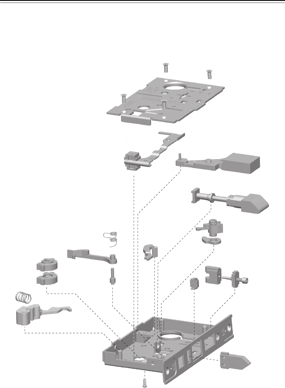
Mortise Case Parts
4–24 40H Series Service Manual
HFUNCTION CASE—HOTEL LOCK
HJ FUNCTION CASE—HOTEL LOCK
TD FUNCTION CASE—DORMITORY LOCK
Figure 4.12 H, HJ, TD function case exploded diagram
1
2
3
4
5
6
7
8
9
10
11
13
14
15
12
16
17
18
20
19

Mortise Case Parts
40H Series Service Manual 4–25
H, HJ, TD function
case parts list
Refer to Figure 4.12 and the table below to find the part you need.
Item Part No.a
a. For a complete case, use C45516. To order a “case only” lock, which includes a
mortise case, faceplate, and strike, see page 4–62.
Qty. Description
1 A34087 4 Case cover mounting screw
2 D44010 1 Cover
3 C45032 1 “F” Locking lever sub-assembly
4 B45060 1 Deadbolt sub-assembly
5 B45020 1 Latchbolt sub-assembly
6 C44104 1 Turn knob hub (deadbolt)
7 B34032 1 Turn knob hub cam
8 C44110 1 Key release lever
9 C44144 1 Cylinder retainer
10 B45090 1 Cylinder retainer assembly
11 B44166 1 Fusible link molded assembly
12 C44142 1 Auxiliary bolt
13 B44194 1 Deadlocking lever spring
14 C44148 1 Deadlocking lever
15 A44184 1 Deadlocking lever pin
16 C44146 2 Hub
17 A44193 1 Release lever spring
18 C45010 1 Release lever sub-assembly
19 A44234 1 Self tapping screw
20 C45000 1 Case sub-assembly
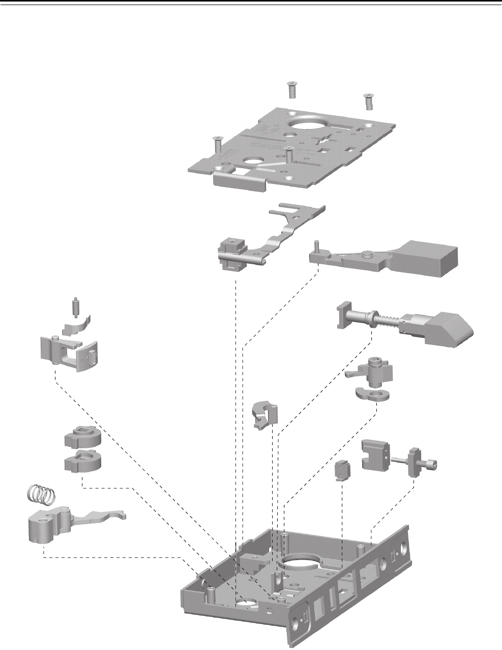
Mortise Case Parts
4–26 40H Series Service Manual
IND FUNCTION CASE—INTRUDER LOCK
TFUNCTION CASE—DORMITORY LOCK
Figure 4.13 IND, T function case exploded diagram
1
2
3
4
5
6
7
8
9
10
11
12
13
14
15
16
17
18

Mortise Case Parts
40H Series Service Manual 4–27
IND, T case
parts list
Refer to Figure 4.13 and the table below to find the part you need.
Item Part No.a
a. For a complete case, use C45500. To order a “case only” lock, which includes a
mortise case, faceplate, and strike, see page 4–62.
Qty. Description
1 A34087 4 Case cover mounting screw
2 D44010 1 Cover
3 C45030 1 Locking lever and toggle assembly
4 B45060 1 Deadbolt sub-assembly
5 B45020 1 Latchbolt sub-assembly
6 C44104 1 Turn knob hub (deadbolt)
7 B34032 1 Turn knob hub cam
8 C44110 1 Key release lever
9 C44144 1 Cylinder retainer
10 B45090 1 Cylinder retainer assembly
11 B44166 1 Fusible link molded assembly
12 A44188 1 Toggle roller
13 B44190 1 Toggle lever spring
14 C44100 1 Toggle lever
15 C44146 2 Hub
16 A44193 1 Release lever spring
17 C45010 1 Release lever sub-assembly
18 C45000 1 Case sub-assembly

Mortise Case Parts
4–28 40H Series Service Manual
LFUNCTION CASE—PRIVACY LOCK
Figure 4.14 L function case exploded diagram
1
2
3
4
5
6
7
8
9
10
11
12
13
14
15
16

Mortise Case Parts
40H Series Service Manual 4–29
L function case
parts list
Refer to Figure 4.14 and the table below to find the part you need.
Item Part No.a
a. For a complete case, use C45509. To order a “case only” lock, which includes a
mortise case, faceplate, and strike, see page 4–62.
Qty. Description
1 A34087 4 Case cover mounting screw
2 D44010 1 Cover
3 C45030 1 Locking lever and toggle assembly
4 B45060 1 Deadbolt sub-assembly
5 B45020 1 Latchbolt sub-assembly
6 C44104 1 Turn knob hub (deadbolt)
7 B34032 1 Turn knob hub cam
8 C44110 1 Key release lever
9 B44166 1 Fusible link molded assembly
10 A44188 1 Toggle roller
11 B44190 1 Toggle lever spring
12 C44100 1 Toggle lever
13 C44146 2 Hub
14 A44193 1 Release lever spring
15 C45010 1 Release lever sub-assembly
16 C45000 1 Case sub-assembly
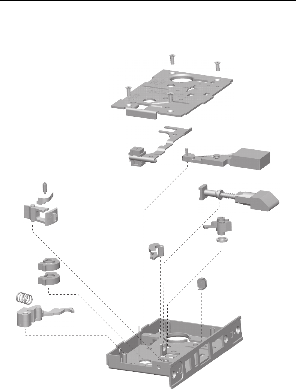
Mortise Case Parts
4–30 40H Series Service Manual
LB FUNCTION CASE—PRIVACY LOCK
Figure 4.15 LB function case exploded diagram
1
2
3
4
5
6
7
8
9
10
11
12
13
14
15
16

Mortise Case Parts
40H Series Service Manual 4–31
LB function case
parts list
Refer to Figure 4.15 and the table below to find the part you need.
Item Part No.a
a. For a complete case, use C45511. To order a “case only” lock, which includes a
mortise case, faceplate, and strike, see page 4–62.
Qty. Description
1 A34087 4 Case cover mounting screw
2 D44010 1 Cover
3 C45030 1 Locking lever and toggle assembly
4 B45060 1 Deadbolt sub-assembly
5 B45020 1 Latchbolt sub-assembly
6 C44104 1 Turn knob hub (deadbolt)
7 A34120 1 Turn knob hub spacer
8 C44110 1 Key release lever
9 B44166 1 Fusible link molded assembly
10 A44188 1 Toggle roller
11 B44190 1 Toggle lever spring
12 C44100 1 Toggle lever
13 C44146 2 Hub
14 A44193 1 Release lever spring
15 C45010 1 Release lever sub-assembly
16 C45000 1 Case sub-assembly

Mortise Case Parts
4–32 40H Series Service Manual
TA FUNCTION CASE—DORMITORY LOCK
Figure 4.16 TA function case exploded diagram
1
2
3
4
5
6
7
8
9
10
11
12
13
14
15
16
17
18

Mortise Case Parts
40H Series Service Manual 4–33
TA function case
parts list
Refer to Figure 4.16 and the table below to find the part you need.
Item Part No.a
a. For a complete case, use C45515. To order a “case only” lock, which includes a
mortise case, faceplate, and strike, see page 4–62.
Qty. Description
1 A34087 4 Case cover mounting screw
2 D44010 1 Cover
3 C45032 1 “F” Locking lever sub-assembly
4 B45060 1 Deadbolt sub-assembly
5 B45020 1 Latchbolt sub-assembly
6 C44104 1 Turn knob hub (deadbolt)
7 B34032 1 Turn knob hub cam
8 C44110 1 Key release lever
9 C44144 1 Cylinder retainer
10 B45090 1 Cylinder retainer assembly
11 B44166 1 Fusible link molded assembly
12 A44188 1 Toggle roller
13 B44190 1 Toggle lever spring
14 C44100 1 Toggle lever
15 C44146 2 Hub
16 A44193 1 Release lever spring
17 C45010 1 Release lever sub-assembly
18 C45000 1 Case sub-assembly
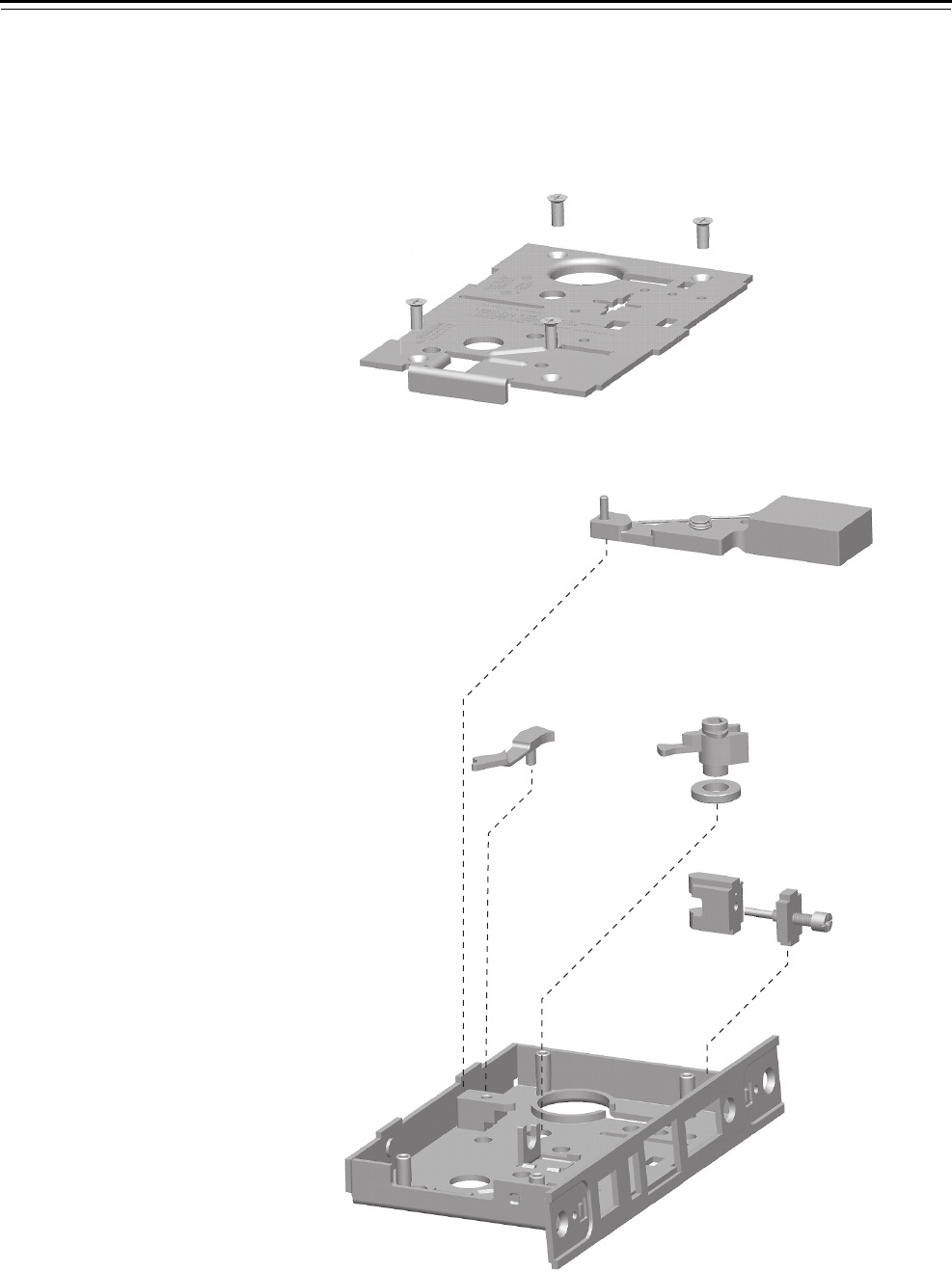
Mortise Case Parts
4–34 40H Series Service Manual
AD FUNCTION CASE—DEADLOCK
WD FUNCTION CASE—DEADLOCK
YD FUNCTION CASE—DEADLOCK
Figure 4.17 AD, WD, YD function case exploded diagram
1
2
3
4
5
6
7
8
9

Mortise Case Parts
40H Series Service Manual 4–35
AD, WD, YD function
case parts list
Refer to Figure 4.17 and the table below to find the part you need.
Item Part No.a
a. For a complete case, use C45512. To order a “case only” lock, which includes a
mortise case, faceplate, and strike, see page 4–62.
Qty. Description
1 A34087 4 Case cover mounting screw
2 D44010 1 Cover
3 B45060 1 Deadbolt sub-assembly
4 C44104 1 Turn knob hub (deadbolt)
5 A34194 1 Spacer for 38/39H
6 C44111 1 Modified key release lever
7 C44144 1 Cylinder retainer
8 B45090 1 Cylinder retainer assembly
9 C45000 1 Case sub-assembly
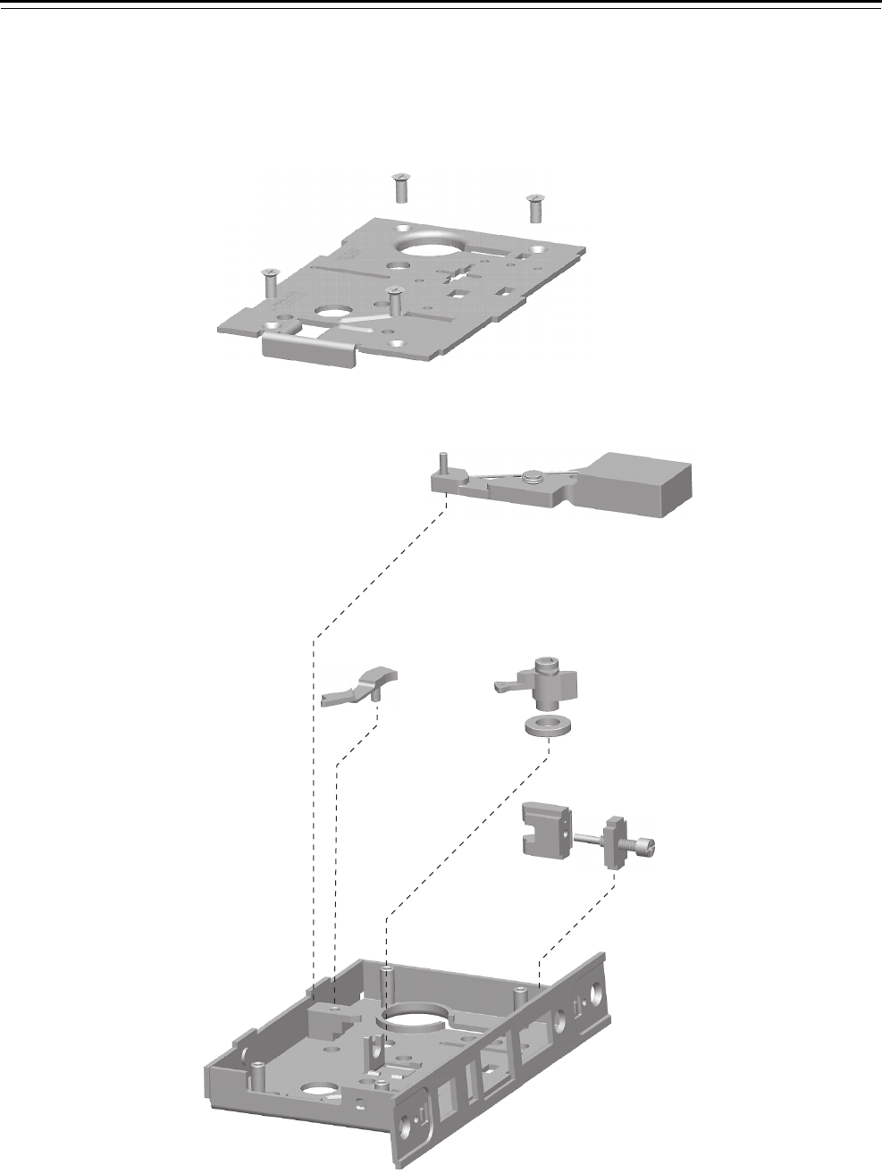
Mortise Case Parts
4–36 40H Series Service Manual
RD FUNCTION CASE—CLASSROOM DEADLOCK
Figure 4.18 RD function case exploded diagram
1
2
3
4
5
6
7
9
8

Mortise Case Parts
40H Series Service Manual 4–37
RD function case
parts list
Refer to Figure 4.18 and the table below to find the part you need.
Item Part No.a
a. For a complete RD (RH) function case, use C45513.
For a complete RD (LH) function case, use C45514.
To order a “case only” lock, which includes a mortise case, faceplate, and strike, see
page 4–62.
Qty. Description
1 A34087 4 Case cover mounting screwb
b. For information to order screws, see page 5–18.
2 D44010 1 Cover
3 B45060 1 Deadbolt sub-assembly
4 C44107 1 Turn knob hub (deadbolt – machined for RD (RH))
not shown C44109 1 Turn knob hub (deadbolt – machined for RD (LH))
5 A34194 1 Spacer for 38/39H
6 C44144 1 Cylinder retainer
7 B45090 1 Cylinder retainer assembly
8 C44111 1 Modified key release lever
9 C45000 1 Case sub-assembly
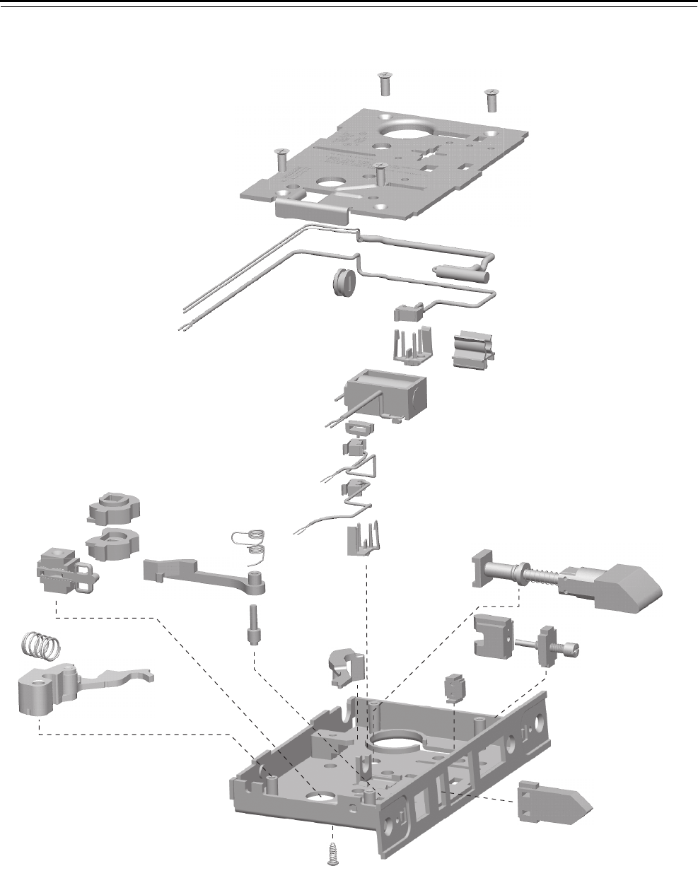
Mortise Case Parts
4–38 40H Series Service Manual
DEL FUNCTION CASE—ELECTRICALLY LOCKED FAIL SAFE LOCK
Figure 4.19 DEL function case exploded diagram
1
2
3
4
7
6
14
15
16
12
23
24 20
21
22
17
27
18
25
11
10
9
8
5
6
26
13
19

Mortise Case Parts
40H Series Service Manual 4–39
DEL function case
parts list
Refer to Figure 4.19 and the table below to find the part you need.
Item Part No.a
a. For a complete case, determine what type of solenoid and optional sensors you need.
Then use the table below to find the part number for the case. To order a “case only”
lock, which includes a mortise case, faceplate, and strike, see page 4–63.
Qty. Description
1 A34087 4 Case cover mounting screw
2 D44010 1 Cover
3 A60452 1 Door status switch
4 B44615 1 Latchbolt sensor switch assembly
5 A34236 1 Wire strain relief
6 B44602 2 RQE and latch status switch holder
7 A44601 1 Door position clip
8 B44613 1 12V solenoid
not shown B44610 1 24V solenoid
9 A44622 1 Strain relief
10 B44616 1 RQE switch assembly (monitors cover side)
11 B44624 1 RQE switch assembly (monitors case side)
12 C44110 1 Key release lever
13 B45020 1 Latchbolt sub-assembly
14 C44144 1 Cylinder retainer
15 B45090 1 Cylinder retainer assembly
16 B44166 1 Fusible link molded assembly
17 C44142 1 Auxiliary bolt
18 C45000 1 Case sub-assembly
19 A44234 1 Self tapping screw
20 B44194 1 Deadlocking lever spring
21 C44148 1 Deadlocking lever
22 A44184 1 Deadlocking lever pin
23 C44539 1 Electrified hub (RH)
24 C44538 1 Electrified hub (LH)
25 b
b. To obtain the parts for the electronic locking toggle assembly, order:
❥locking slide (B44611)
❥locking bar (A44612)
❥electronic locking toggle (B44627)
❥toggle screws (see Screw kits on page 5–19).
1 Electronic locking toggle assembly
26 A44193 1 Release lever spring
27 C45010 1 Release lever sub-assembly
Sensors Case part number
Door Latch RQE 12 V solenoid 24 V solenoid
■C45710 C45711
■C45563 C45568
■C45564 C45569
■■
C45562 C45567
■■C45566 C45571
■■■C45565 C45570
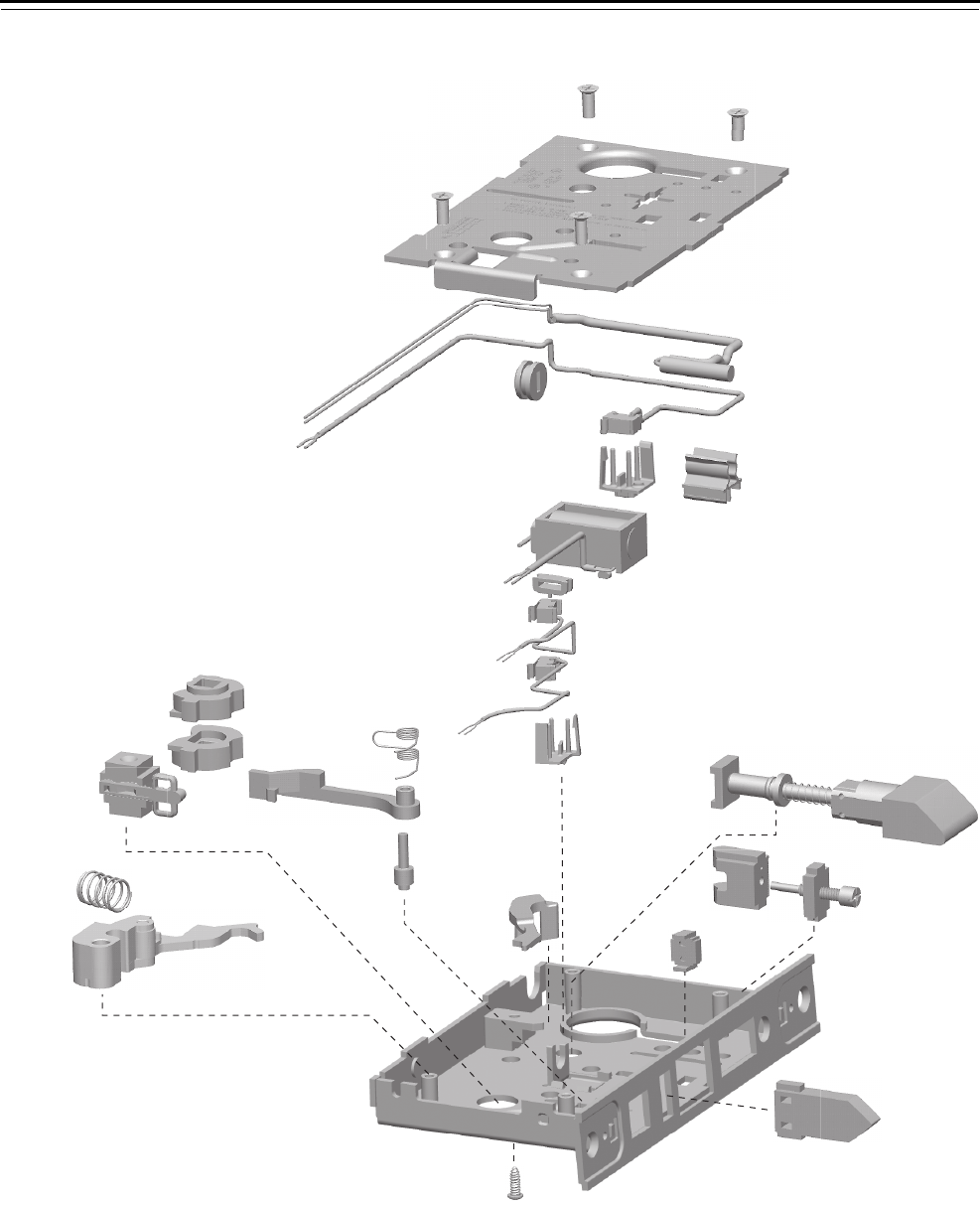
Mortise Case Parts
4–40 40H Series Service Manual
DEU FUNCTION CASE—ELECTRICALLY UNLOCKED FAIL SECURE
Figure 4.20 DEU function case exploded diagram
1
2
3
4
7
6
14
15
16
12
23
24 20
21
22
17
27
18
25
11
10
9
8
5
6
26
19
13

Mortise Case Parts
40H Series Service Manual 4–41
DEU function case
parts list
Refer to Figure 4.20 and the table below to find the part you need.
Item Part No.a
a. For a complete case, determine what type of solenoid and optional sensors you need.
Then use the table below to find the part number for the case. To order a “case only”
lock, which includes a mortise case, faceplate, and strike, see page 4–63.
Qty. Description
1 A34087 4 Case cover mounting screw
2 D44010 1 Cover
3 A60452 1 Door status switch
4 B44615 1 Latchbolt sensor switch assembly
5 A34236 1 Wire strain relief
6 B44602 2 RQE and latch status switch holder
7 A44601 1 Door position clip
8 B44613 1 12V solenoid
not shown B44610 1 24V solenoid
9 A44622 1 Strain relief
10 B44616 1 RQE switch assembly (monitors cover side)
11 B44624 1 RQE switch assembly (monitors case side)
12 C44110 1 Key release lever
13 B45020 1 Latchbolt sub-assembly
14 C44144 1 Cylinder retainer
15 B45090 1 Cylinder retainer assembly
16 B44166 1 Fusible link molded assembly
17 C44142 1 Auxiliary bolt
18 C45000 1 Case sub-assembly
19 A44234 1 Self tapping screw
20 B44194 1 Deadlocking lever spring
21 C44148 1 Deadlocking lever
22 A44184 1 Deadlocking lever pin
23 C44539 1 Electrified hub (RH)
24 C44538 1 Electrified hub (LH)
25 b
b. To obtain the parts for the electronic locking toggle assembly, order:
❥locking slide (B44611)
❥locking bar (A44612)
❥electronic locking toggle (B44627)
❥toggle screws (see Screw kits on page 5–19).
Electronic locking toggle assembly
26 A44193 1 Release lever spring
27 C45010 1 Release lever sub-assembly
Sensors Case part number
Door Latch RQE 12 V solenoid 24 V solenoid
■C45708 C45709
■C45552 C45557
■C45553 C45558
■■C45555 C45560
■■
C45551 C45556
■■■C45554 C45559
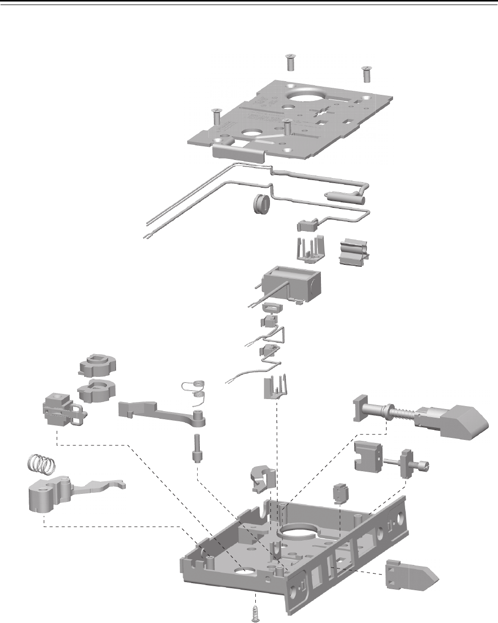
Mortise Case Parts
4–42 40H Series Service Manual
WEL FUNCTION CASE—ELECTRICALLY UNLOCKED FAIL SAFE
Figure 4.21 WEL function case exploded diagram
1
2
3
4
7
6
14
15
16
12
23
24 20
21
22
17
27
18
25
11
10
9
8
5
6
26
1
19
13

Mortise Case Parts
40H Series Service Manual 4–43
WEL function case
parts list
Refer to Figure 4.21 and the table below to find the part you need.
Item Part No.a
a. For a complete case, determine what type of solenoid and optional sensors you need.
Then use the table below to find the part number for the case. To order a “case only”
lock, which includes a mortise case, faceplate, and strike, see page 4–63.
Qty. Description
1 A34087 4 Case cover mounting screw
2 D44010 1 Cover
3 A60452 1 Door status switch
4 B44615 1 Latchbolt sensor switch assembly
5 A34236 1 Wire strain relief
6 B44602 2 RQE and latch status switch holder
7 A44601 1 Door position clip
8 B44613 1 12V solenoid
not shown B44610 1 24V solenoid
9 A44622 1 Strain relief
10 B44616 1 RQE switch assembly (monitors cover side)
11 B44624 1 RQE switch assembly (monitors case side)
12 C44110 1 Key release lever
13 B45020 1 Latchbolt sub-assembly
14 C44144 1 Cylinder retainer
15 B45090 1 Cylinder retainer assembly
16 B44166 1 Fusible link molded assembly
17 C44142 1 Auxiliary bolt
18 C45000 1 Case sub-assembly
19 A44234 1 Self tapping screw
20 B44194 1 Deadlocking lever spring
21 C44148 1 Deadlocking lever
22 A44184 1 Deadlocking lever pin
23 C44538 1 Electrified hub (LH)
24 C44539 1 Electrified hub (RH)
25 b
b. To obtain the parts for the electronic locking toggle assembly, order:
■locking slide (B44611)
■locking bar (A44612)
■electronic locking toggle (B44627)
■toggle screws (see Screw kits on page 5–19).
1 Electronic locking toggle assembly
26 A44193 1 Release lever spring
27 C45010 1 Release lever sub-assembly
Sensors Case part number
Door Latch RQE 12 V solenoid 24 V solenoid
■C45714 C45715
■C45683 C45688
■C45684 C45689
■■C45686 C45691
■■
C45682 C45687
■■■C45685 C45690
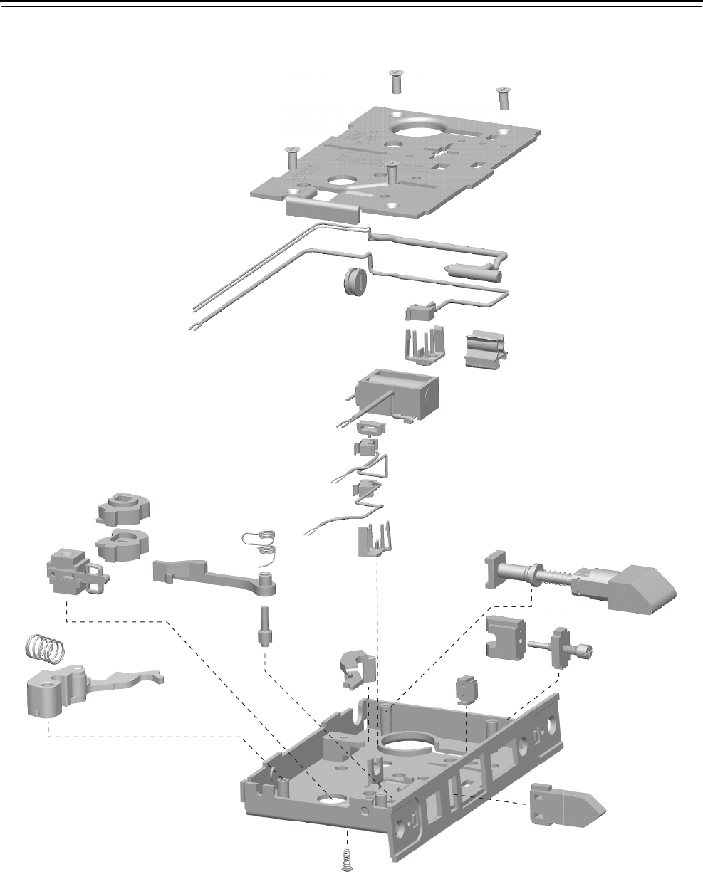
Mortise Case Parts
4–44 40H Series Service Manual
WEU FUNCTION CASE—ELECTRICALLY UNLOCKED FAIL SECURE
Figure 4.22 WEU function case exploded diagram
1
2
3
4
7
6
14
15
16
12
23
24 20
21
22
17
27
18
25
11
10
9
8
5
6
26
19
13

Mortise Case Parts
40H Series Service Manual 4–45
WEU function case
parts list
Refer to Figure 4.22 and the table below to find the part you need.
Item Part No.a
a. For a complete case, determine what type of solenoid and optional sensors you need.
Then use the table below to find the part number for the case. To order a “case only”
lock, which includes a mortise case, faceplate, and strike, see page 4–63.
Qty. Description
1 A34087 4 Case cover mounting screw
2 D44010 1 Cover
3 A60452 1 Door status switch
4 B44615 1 Latchbolt sensor switch assembly
5 A34236 1 Wire strain relief
6 B44602 2 RQE and latch status switch holder
7 A44601 1 Door position clip
8 B44613 1 12V solenoid
not shown B44610 1 24V solenoid
9 A44622 1 Strain relief
10 B44616 1 RQE switch assembly (monitors cover side)
11 B44624 1 RQE switch assembly (monitors case side)
12 C44110 1 Key release lever
13 B45020 1 Latchbolt sub-assembly
14 C44144 1 Cylinder retainer
15 B45090 1 Cylinder retainer assembly
16 B44166 1 Fusible link molded assembly
17 C44142 1 Auxiliary bolt
18 C45000 1 Case sub-assembly
19 A44234 1 Self tapping screw
20 B44194 1 Deadlocking lever spring
21 C44148 1 Deadlocking lever
22 A44184 1 Deadlocking lever pin
23 C44538 1 Electrified hub (LH)
24 C44539 1 Electrified hub (RH)
25 b
b. To obtain the parts for the electronic locking toggle assembly, order:
■locking slide (B44611)
■locking bar (A44612)
■electronic locking toggle (B44627)
■toggle screws (see Screw kits on page 5–19).
1 Electronic locking toggle assembly
26 A44193 1 Release lever spring
27 C45010 1 Release lever sub-assembly
Sensors Case part number
Door Latch RQE 12 V solenoid 24 V solenoid
■C45712 C45713
■C45672 C45677
■C45673 C45678
■■C45675 C45680
■■
C45671 C45676
■■■C45674 C45679
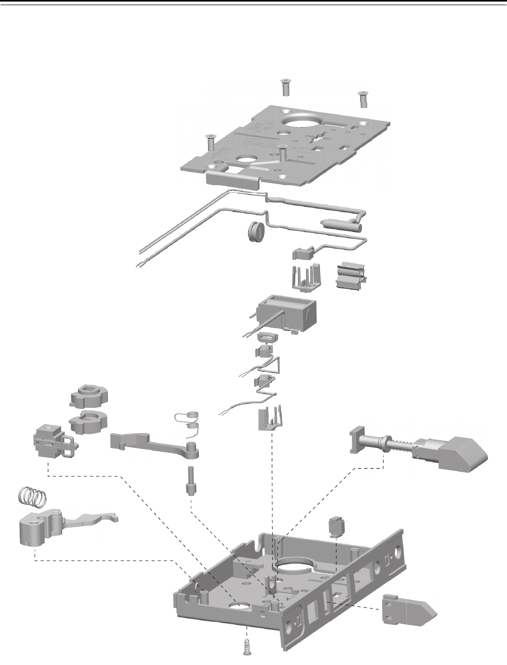
Mortise Case Parts
4–46 40H Series Service Manual
NXEL FUNCTION CASE—ELECTRICALLY LOCKED FAIL SAFE LOCK
Figure 4.23 NXEL function case exploded diagram
1
2
3
4
7
6
13
20
21 17
18
19
14
24
15
22
11
10
9
8
5
6
23
16
12

Mortise Case Parts
40H Series Service Manual 4–47
NXEL function case
parts list
Refer to Figure 4.23 and the table below to find the part you need.
Item Part No.a
a. For a complete case, determine what type of solenoid and optional sensors you need.
Then use the table below to find the part number for the case. To order a “case only”
lock, which includes a mortise case, faceplate, and strike, see page 4–63.
Qty. Description
1 A34087 4 Case cover mounting screw
2 D44010 1 Cover
3 A60452 1 Door status switch
4 B44615 1 Latchbolt sensor switch assembly
5 A34236 1 Wire strain relief
6 B44602 2 RQE and latch status switch holder
7 A4601 1 Door position clip
8 B44613 1 12 V solenoid
not shown B44610 1 24 V solenoid
9 A44622 1 Strain relief
10 B44616 1 RQE switch assembly (monitors cover side)
11 B44624 1 RQE switch assembly (monitors case side)
12 B45020 1 Latchbolt sub-assembly
13 B44166 1 Fusible link molded assembly
14 C44142 1 Auxiliary bolt
15 C45000 1 Case sub-assembly
16 A44234 1 Self tapping screw
17 B44194 1 Deadlocking lever spring
18 C44148 1 Deadlocking lever
19 A44184 1 Deadlocking lever pin
20 C44538 1 Electrified hub (LH)
21 C44539 1 Electrified hub (RH)
22 b
b. To obtain the parts for the electronic locking toggle assembly, order:
■locking slide (B44611)
■locking bar (A44612)
■electronic locking toggle (B44627)
■toggle screws (see Screw kits on page 5–19).
1 Electronic locking toggle assembly
23 A44193 1 Release lever spring
24 C45010 1 Release lever sub-assembly
Sensors Case part number
Door Latch RQE 12 V solenoid 24 V solenoid
■C45706 C45707
■C45541 C45546
■C45542 C45547
■■ C45544 C45549
■■
C45540 C45545
■■■ C45543 C45548

Mortise Case Parts
4–48 40H Series Service Manual
NXEU FUNCTION CASE—ELECTRICALLY UNLOCKED FAIL SECURE LOCK
Figure 4.24 NXEU function case exploded diagram
1
2
3
4
7
6
13
20
21 17
18
19
14
24
15
22
11
10
9
8
5
6
23
16
12

Mortise Case Parts
40H Series Service Manual 4–49
NXEU function case
parts list
Refer to Figure 4.24 and the table below to find the part you need.
Item Part No.a
a. For a complete case, determine what type of solenoid and optional sensors you need.
Then use the table below to find the part number for the case. To order a “case only”
lock, which includes a mortise case, faceplate, and strike, see page 4–63.
Qty. Description
1 A34087 4 Case cover mounting screw
2 D44010 1 Cover
3 A60452 1 Door status switch
4 B44615 1 Latchbolt sensor switch assembly
5 A34236 1 Wire strain relief
6 B44602 2 RQE and latch status switch holder
7 A4601 1 Door position clip
8 B44613 1 12 V solenoid
not shown B44610 1 24 V solenoid
9 A44622 1 Strain relief
10 B44616 1 RQE switch assembly (monitors cover side)
11 B44624 1 RQE switch assembly (monitors case side)
12 B45020 1 Latchbolt sub-assembly
13 B44166 1 Fusible link molded assembly
14 C44142 1 Auxiliary bolt
15 C45000 1 Case sub-assembly
16 A44234 1 Self tapping screw
17 B44194 1 Deadlocking lever spring
18 C44148 1 Deadlocking lever
19 A44184 1 Deadlocking lever pin
20 C44538 1 Electrified hub (LH)
21 C44539 1 Electrified hub (RH)
22 b
b. To obtain the parts for the electronic locking toggle assembly, order:
■locking slide (B44611)
■locking bar (A44612)
■electronic locking toggle (B44627)
■toggle screws (see Screw kits on page 5–19).
1 Electronic locking toggle assembly
23 A44193 1 Release lever spring
24 C45010 1 Release lever sub-assembly
Sensors Case part number
Door Latch RQE 12 V solenoid 24 V solenoid
■C45704 C45705
■C45530 C45535
■C45531 C45536
■■C45533 C45538
■■
C45529 C45534
■■■C45532 C45537
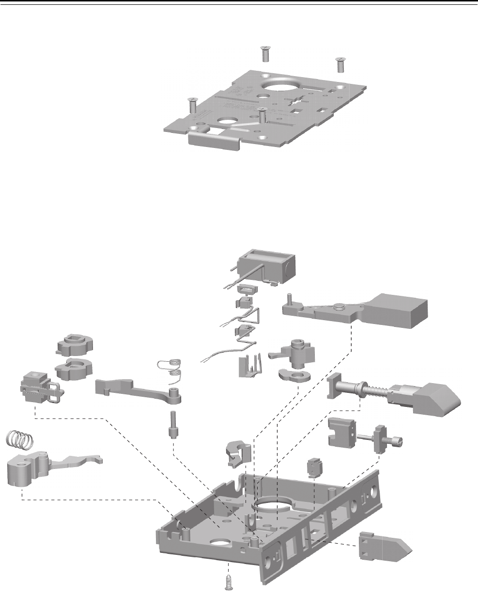
Mortise Case Parts
4–50 40H Series Service Manual
TDEL FUNCTION CASE—ELECTRICALLY LOCKED FAIL SAFE LOCK
Figure 4.25 TDEL function case exploded diagram
1
2
12
11
13
14
15
8
22
23 19
20
21
16
17
24
10
26
18
3
6
5
4
9
25
7

Mortise Case Parts
40H Series Service Manual 4–51
TDEL function case
parts list
Refer to Figure 4.25 and the table below to find the part you need.
Item Part No.a
a. For a complete case, determine what type of solenoid and optional sensors you need.
Then use the table below to find the part number for the case. To order a “case only”
lock, which includes a mortise case, faceplate, and strike, see page 4–63.
Qty. Description
1 A34087 4 Case cover mounting screw
2 D44010 1 Cover
3 B44613 1 12V solenoid
not shown B44610 1 24V solenoid
4 A44622 1 Strain relief
5 B44616 1 RQE switch assembly (monitors cover side)
6 B44624 1 RQE switch assembly (monitors case side)
7 B44602 1 RQE and latch status switch holder
8 C44110 1 Key release lever
9 B45060 1 Deadbolt sub-assembly
10 C44104 1 Turn knob hub (deadbolt)
11 B34032 1 Turn knob hub cam
12 B45020 1 Latchbolt sub-assembly
13 C44144 1 Cylinder retainer
14 B45090 1 Cylinder retainer assembly
15 B44166 1 Fusible link molded assembly
16 C44142 1 Auxiliary bolt
17 C45000 1 Case sub-assembly
18 A44234 1 Self tapping screw
19 B44194 1 Deadlocking lever spring
20 C44148 1 Deadlocking lever
21 A44184 1 Deadlocking lever pin
22 C44538 1 Electrified hub (LH)
23 C44539 1 Electrified hub (RH)
24 b
b. To obtain the parts for the electronic locking toggle assembly, order:
■locking slide (B44611)
■locking bar (A44612)
■electronic locking toggle (B44627)
■toggle screws (see Screw kits on page 5–19).
Electronic locking toggle assembly
25 A44193 Release lever spring
26 C45010 1 Release lever sub-assembly
Sensors Case part number
RQE 12 V solenoid 24 V solenoid
■C45591 C45592
C45728 C45729
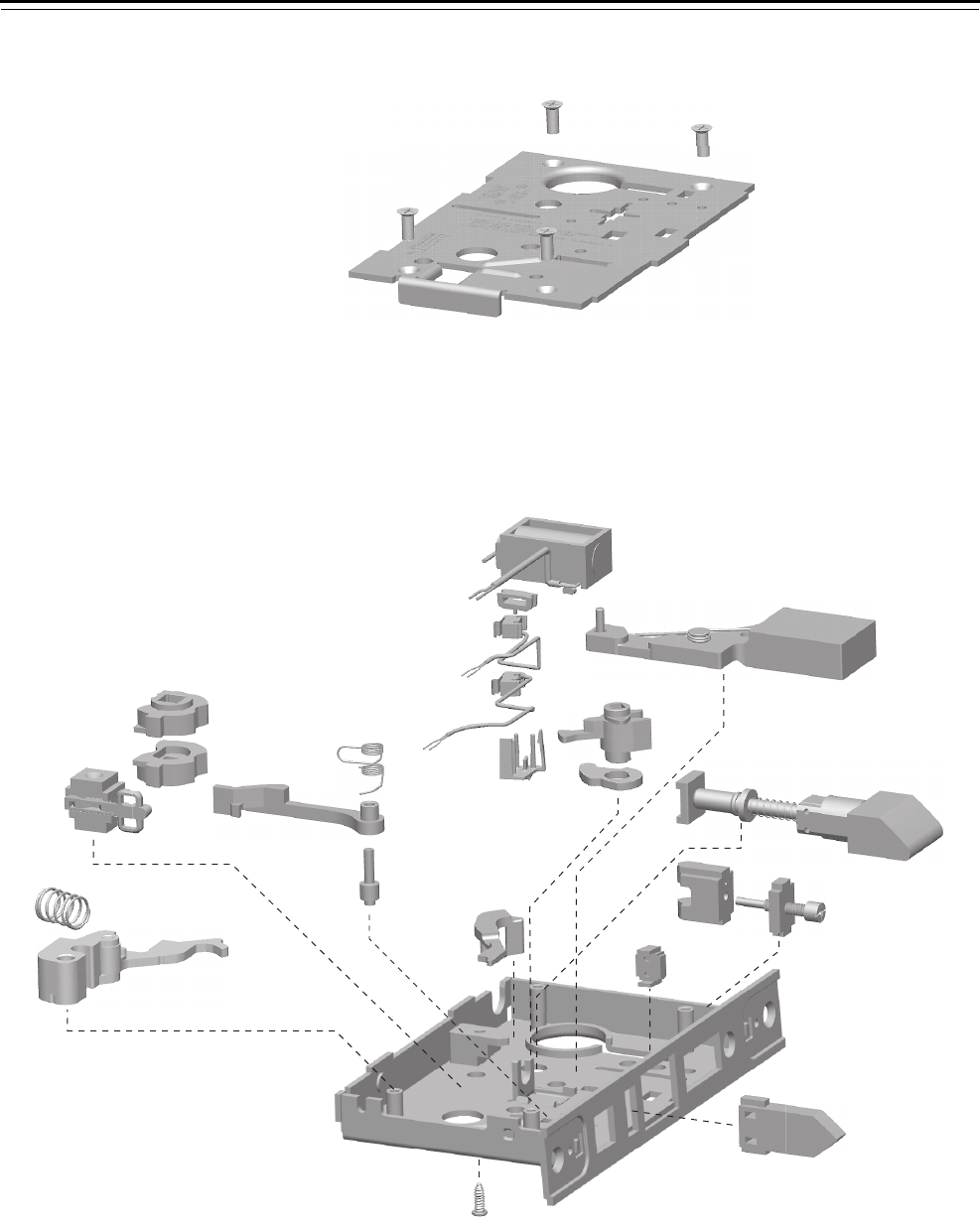
Mortise Case Parts
4–52 40H Series Service Manual
TDEU FUNCTION CASE—ELECTRICALLY UNLOCKED FAIL SECURE
Figure 4.26 TDEU function case exploded diagram
1
2
12
11
13
14
15
8
22
23 19
20
21
16
17
24
10
26
18
3
6
5
4
9
25
7

Mortise Case Parts
40H Series Service Manual 4–53
TDEU function case
parts list
Refer to Figure 4.2 and the table below to find the part you need.
Item Part No.a
a. For a complete case, determine what type of solenoid and optional sensors you need.
Then use the table below to find the part number for the case. To order a “case only”
lock, which includes a mortise case, faceplate, and strike, see page 4–63.
Qty. Description
1 A34087 4 Case cover mounting screw
2 D44010 1 Cover
3 B44613 1 12V solenoid
not shown B44610 1 24V solenoid
4 A44622 1 Strain relief
5 B44616 1 RQE switch assembly (monitors cover side)
6 B44624 1 RQE switch assembly (monitors case side)
7 B44602 1 RQE and latch status switch holder
8 C44110 1 Key release lever
9 B45060 1 Deadbolt sub-assembly
10 C44104 1 Turn knob hub (deadbolt)
11 B34032 1 Turn knob hub cam
12 B45020 1 Latchbolt sub-assembly
13 C44144 1 Cylinder retainer
14 B45090 1 Cylinder retainer assembly
15 B44166 1 Fusible link molded assembly
16 C44142 1 Auxiliary bolt
17 C45000 1 Case sub-assembly
18 A44234 1 Self tapping screw
19 B44194 1 Deadlocking lever spring
20 C44148 1 Deadlocking lever
21 A44184 1 Deadlocking lever pin
22 C44538 1 Electrified hub (LH)
23 C44539 1 Electrified hub (RH)
24 b
b. To obtain the parts for the electronic locking toggle assembly, order:
■locking slide (B44611)
■locking bar (A44612)
■electronic locking toggle (B44627)
■toggle screws (see Screw kits on page 5–19).
Electronic locking toggle assembly
25 A44193 1 Release lever spring
26 C45010 1 Release lever sub-assembly
Sensor Case part number
RQE 12 V solenoid 24 V solenoid
■C45586 C45586
C45724 C45725
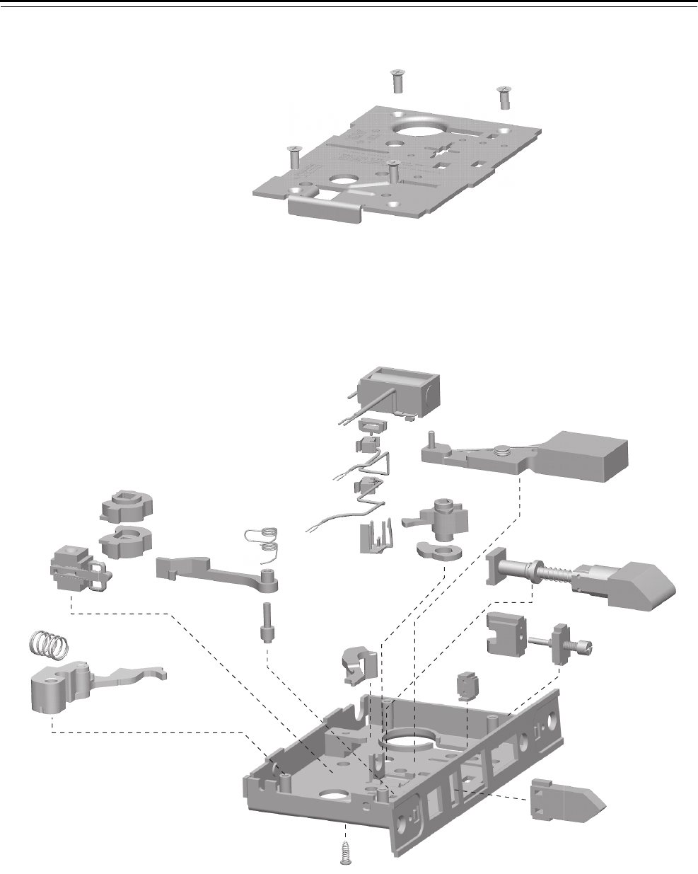
Mortise Case Parts
4–54 40H Series Service Manual
TWEL FUNCTION CASE—ELECTRICALLY LOCKED FAIL SAFE LOCK
Figure 4.27 TWEL function case exploded diagram
1
2
12
11
13
14
15
8
22
23 19
20
21
16
17
24
10
26
18
3
6
5
4
9
25
7

Mortise Case Parts
40H Series Service Manual 4–55
TWEL function case
parts list
Refer to Figure 4.2 and the table below to find the part you need.
Item Part No.a
a. For a complete case, determine what type of solenoid and optional sensors you need.
Then use the table below to find the part number for the case. To order a “case only”
lock, which includes a mortise case, faceplate, and strike, see page 4–63.
Qty. Description
1 A34087 4 Case cover mounting screw
2 D44010 1 Cover
3 B44613 1 12V solenoid
not shown B44610 1 24V solenoid
4 A44622 1 Strain relief
5 B44616 1 RQE switch assembly (monitors cover side)
6 B44624 1 RQE switch assembly (monitors case side)
7 B44602 1 RQE and latch status switch holder
8 C44110 1 Key release lever
9 B45060 1 Deadbolt sub-assembly
10 C44104 1 Turn knob hub (deadbolt)
11 A34032 1 Turn knob hub cam
12 B45020 1 Latchbolt sub-assembly
13 C44144 1 Cylinder retainer
14 B45090 1 Cylinder retainer assembly
15 B44166 1 Fusible link molded assembly
16 C44142 1 Auxiliary bolt
17 C45000 1 Case sub-assembly
18 A44234 1 Self tapping screw
19 B44194 1 Deadlocking lever spring
20 C44148 1 Deadlocking lever
21 A44184 1 Deadlocking lever pin
22 C44538 1 Electrified hub (LH)
23 C44539 1 Electrified hub (RH)
24 b
b. To obtain the parts for the electronic locking toggle assembly, order:
■locking slide (B44611)
■locking bar (A44612)
■electronic locking toggle (B44627)
■toggle screws (see Screw kits on page 5–19).
1 Electronic locking toggle assembly
25 A44193 1 Release lever spring
26 C45010 1 Release lever sub-assembly
Sensors Case part number
RQE 12 V solenoid 24 V solenoid
■C45699 C45700
C45736 C45737
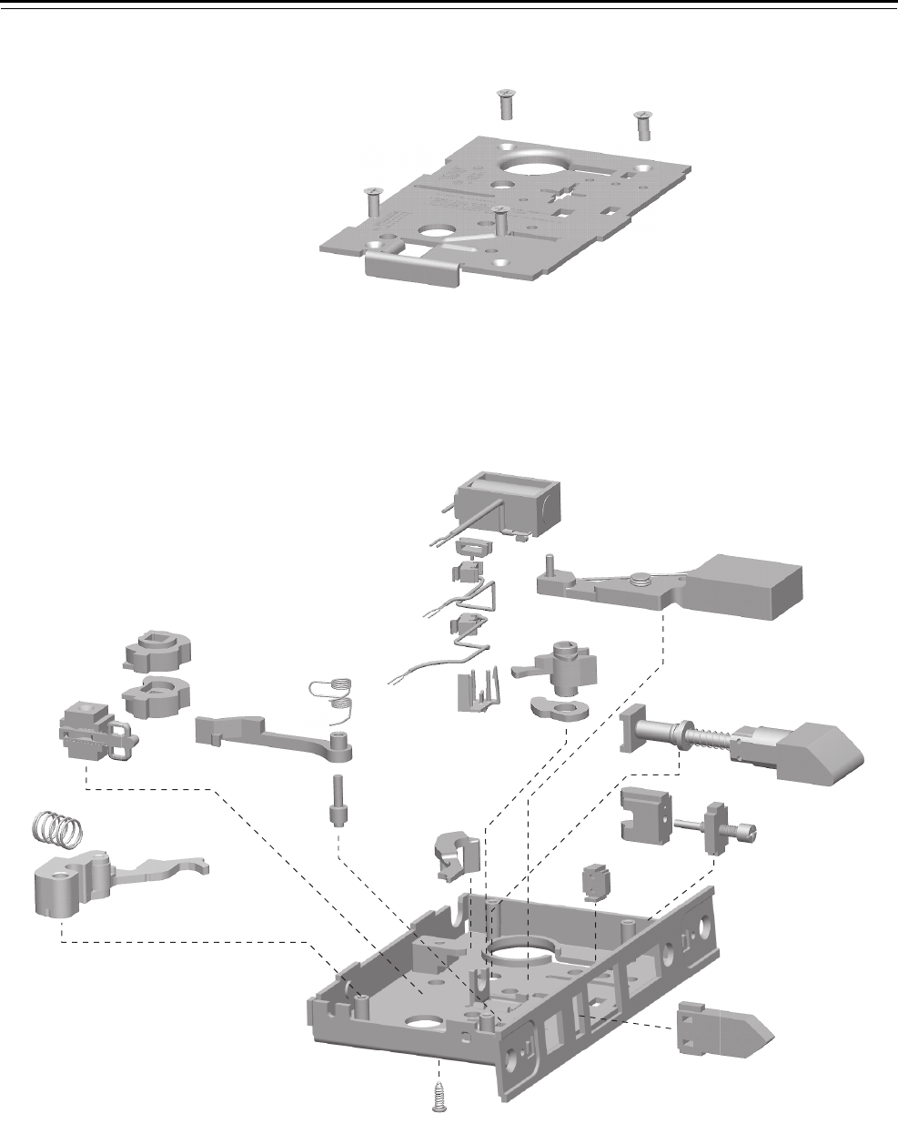
Mortise Case Parts
4–56 40H Series Service Manual
TWEU FUNCTION CASE—ELECTRICALLY UNLOCKED FAIL SECURE
Figure 4.28 TWEU function case exploded diagram
1
2
12
11
13
14
15
8
22
23 19
20
21
16
17
24
10
26
18
3
6
5
4
9
25
7

Mortise Case Parts
40H Series Service Manual 4–57
TWEU function case
parts list
Refer to Figure 4.2 and the table below to find the part you need.
Item Part No.a
a. For a complete case, determine what type of solenoid and optional sensors you need.
Then use the table below to find the part number for the case. To order a “case only”
lock, which includes a mortise case, faceplate, and strike, see page 4–63.
Qty. Description
1 A34087 4 Case cover mounting screw
2 D44010 1 Cover
3 B44613 1 12V solenoid
not shown B44610 1 24V solenoid
4 A44622 1 Strain relief
5 B44616 1 RQE switch assembly (monitors cover side)
6 B44624 1 RQE switch assembly (monitors case side)
7 B44602 1 RQE and latch status switch holder
8 C44110 1 Key release lever
9 B45060 1 Deadbolt sub-assembly
10 C44104 1 Turn knob hub (deadbolt)
11 A34032 1 Turn knob hub cam
12 B45020 1 Latchbolt sub-assembly
13 C44144 1 Cylinder retainer
14 B45090 1 Cylinder retainer assembly
15 B44166 1 Fusible link molded assembly
16 C44142 1 Auxiliary bolt
17 C45000 1 Case sub-assembly
18 A44234 1 Self tapping screw
19 B44194 1 Deadlocking lever spring
20 C44148 1 Deadlocking lever
21 A44184 1 Deadlocking lever pin
22 C44538 1 Electrified hub (LH)
23 C44539 1 Electrified hub (RH)
24 b
b. To obtain the parts for the electronic locking toggle assembly, order:
■locking slide (B44611)
■locking bar (A44612)
■electronic locking toggle (B44627)
■toggle screws (see Screw kits on page 5–19).
1 Electronic locking toggle assembly
25 A44193 1 Release lever spring
Sensors Case part number
RQE 12 V solenoid 24 V solenoid
■C45693 C45694
C45732 C45733
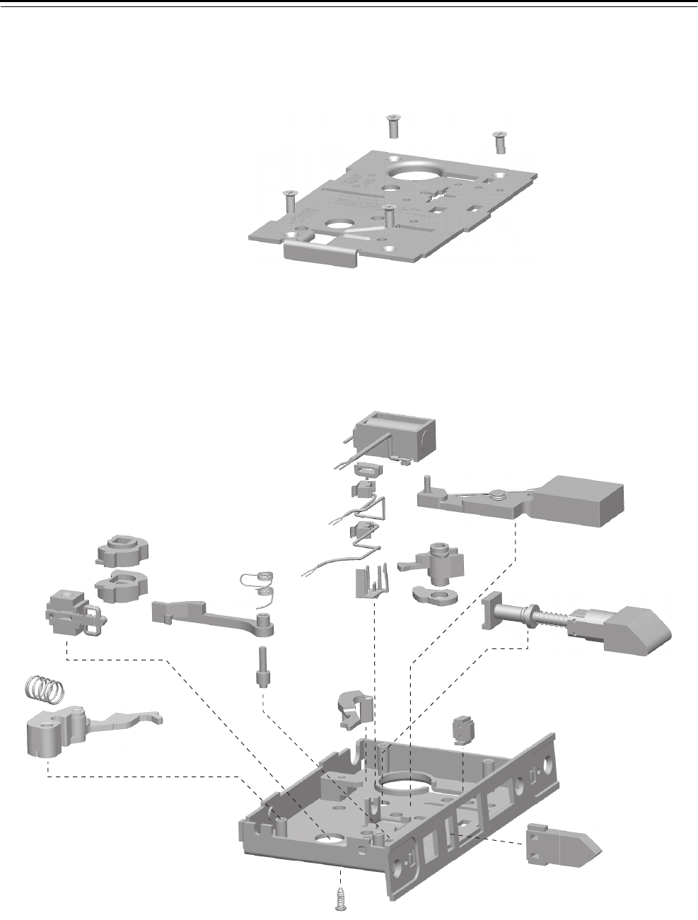
Mortise Case Parts
4–58 40H Series Service Manual
LEL FUNCTION CASE—ELECTRICALLY LOCKED FAIL SAFE LOCK
Figure 4.29 LEL function case exploded diagram
1
2
12
11
13
8
20
21 17
18
19
14
15
22
10
24
16
3
6
5
4
9
23
7

Mortise Case Parts
40H Series Service Manual 4–59
LEL function case
parts list
Refer to Figure 4.29 and the table below to find the part you need.
Item Part No.a
a. For a complete case, determine what type of solenoid and optional sensors you need.
Then use the table below to find the part number for the case. To order a “case only”
lock, which includes a mortise case, faceplate, and strike, see page 4–63.
Qty. Description
1 A34087 4 Case cover mounting screw
2 D44010 1 Cover
3 B44613 1 12V solenoid
not shown B44610 1 24V solenoid
4 A44622 1 Strain relief
5 B44602 2 RQE and latch status switch holder
6 B44616 1 RQE switch assembly (monitors cover side)
7 B44624 1 RQE switch assembly (monitors case side)
8 C44110 1 Key release lever
9 B45060 1 Deadbolt sub-assembly
10 C44104 1 Turn knob hub (deadbolt)
11 A34032 1 Turn knob hub cam
12 B45020 1 Latchbolt sub-assembly
13 B44166 1 Fusible link molded assembly
14 C44142 1 Auxiliary bolt
15 C45000 1 Case sub-assembly
16 A44234 1 Self tapping screw
17 B44194 1 Deadlocking lever spring
18 C44148 1 Deadlocking lever
19 A44184 1 Deadlocking lever pin
20 C44539 1 Electrified hub (RH)
21 C44538 1 Electrified hub (LH)
22 b
b. To obtain the parts for the electronic locking toggle assembly, order:
■locking slide (B44611)
■locking bar (A44612)
■electronic locking toggle (B44627)
■toggle screws (see Screw kits on page 5–19).
Electronic locking toggle assembly
23 A44193 1 Release lever spring
24 C45010 1 Release lever sub-assembly
Sensors Case part number
RQE 12 V solenoid 24 V solenoid
■C45579 C45580
C45720 C45721

Mortise Case Parts
4–60 40H Series Service Manual
LEU FUNCTION CASE—ELECTRICALLY UNLOCKED FAIL SECURE
Figure 4.30 LEU function case exploded diagram
1
2
12
11
13
8
20
21 17
18
19
14
15
22
10
24
16
3
6
5
4
9
23
7

Mortise Case Parts
40H Series Service Manual 4–61
LEU function case
parts list
Refer to Figure 4.30 and the table below to find the part you need.
Item Part No.a
a. For a complete case, determine what type of solenoid and optional sensors you need.
Then use the table below to find the part number for the case. To order a “case only”
lock, which includes a mortise case, faceplate, and strike, see page 4–63.
Qty. Description
1 A34087 4 Case cover mounting screw
2 D44010 1 Cover
3 B44613 1 12V solenoid
not shown B44610 1 24V solenoid
4 A44622 1 Strain relief
5 B44602 2 RQE and latch status switch holder
6 B44616 1 RQE switch assembly (monitors cover side)
7 B44624 1 RQE switch assembly (monitors case side)
8 C44110 1 Key release lever
9 B45060 1 Deadbolt sub-assembly
10 C44104 1 Turn knob hub (deadbolt)
11 A34032 1 Turn knob hub cam
12 B45020 1 Latchbolt sub-assembly
13 B44166 1 Fusible link molded assembly
14 C44142 1 Auxiliary bolt
15 C45000 1 Case sub-assembly
16 A44234 1 Self tapping screw
17 B44194 1 Deadlocking lever spring
18 C44148 1 Deadlocking lever
19 A44184 1 Deadlocking lever pin
20 C44539 1 Electrified hub (RH)
21 C44538 1 Electrified hub (LH)
22 b
b. To obtain the parts for the electronic locking toggle assembly, order:
■locking slide (B44611)
■locking bar (A44612)
■electronic locking toggle (B44627)
■toggle screws (see Screw kits on page 5–19).
Electronic locking toggle assembly
23 A44193 1 Release lever spring
24 C45010 1 Release lever sub-assembly
Sensors Case part number
RQE 12 V solenoid 24 V solenoid
■C45573 C45574
C45716 C45717

Mortise Case Parts
4–62 40H Series Service Manual
CASE ONLY LOCKS
For most functions, 40H Series Locks can be ordered as complete locks
or can be assembled using a “case only” lock, an inside trim kit, and an
outside trim kit. A case only lock includes the items not specifically
associated with inside or outside trim (lock case, faceplate, strike, strike
box, fasteners for case and strike, and installation instructions).
Note: Two faceplates are provided with UNR and UNAB functions.
How to order
standard mortise
locks
To order standard case only locks, use the nomenclature shown in the
example below. To order just a case assembly (without faceplate and
strike) see the function’s case part list in this chapter.
45HCA – R – 626 – RH –
Series:
45HCA – Case only mortise lock
Function code:
AABAD
AT B BA
BW B5 B7
CCHBD
GHHJ
IND INL L
LB LT N
NX R RD
RHB S T
TA TD W
WD XR YD
ZD UNR UNT
UNAB
Finish:
605 606 611
612 613 618
619 625 626
629 630 690
Handing:
No handing
RH
LH
RHRB
LHRB
Options:
SH – Security head screws
7/8-LTC – Flat-lipped strike

Mortise Case Parts
40H Series Service Manual 4–63
How to order
electrified mortise
locks
To order electrified case only locks, use the nomenclature shown in the
example below.
Series:
45HWCA – Case only mortise lock
Function code:
DEL DEU LEL LEU
NXEL NXEU TDEL TDEU
TWEL TWEU WEL WEU
Finish:
605 606 611
612 613 618
619 625 626
629 630 690
Handing:
No handing
RH
LH
RHRB
LHRB
Options:
RQE – Request to exit sensor
LS – Latch status sensor
DS – Door status sensor
24V – 24 volt solenoid
SH – Security head screws
7/8-LTC – Flat-lipped strike
45HWCA – DEL – 626 – RH –
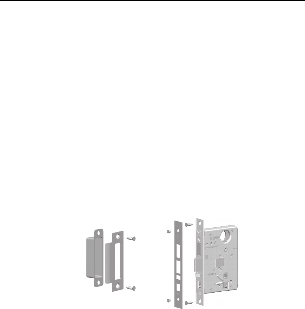
Mortise Case Parts
4–64 40H Series Service Manual
Case only
components
The components of case only locks are described in the table below.
The figure below shows an example of the components included for
each case only lock configuration.
Item Description Qty.
1 40H universal strike box 1
2 40H strikea
a. For strike kit information see page 5–11.
1
3 Strike screw (#12-12 × 3/4″ PHFH)b
b. For information to order screws, see 5–18.
2
not shown Door status magnetc
c. Provided with deadbolt function electrified case only locks with
optional door status monitoring.
1
not shown Door status switchc1
4 Faceplate screw (#8-32 × 1/4″ PHFHMS)b2
5Faceplate
d
d. For faceplate kit information, see page 5–15.
1
6 Case mounting screw (#12-12 × 3/4″ PHFH)b2
7 Mortise case assemblye
e. For part numbers for mortise cases, see the appropriate parts list
in this chapter.
1
Figure 4.31 Case only lock – faceplate and case for AB function shown
123
4
567


Trim Parts
5–2 40H Series Service Manual
OUTSIDE TRIM KITS
How to order To order outside trim kits, use the nomenclature shown in the example
below.
40HTK – OS1 – 14 – H – 626 –
Series:
40HTK – Trim kit
Kit number:
OS1 – Outside lever only
OS21 – Outside lever & cylinder
OS3 – Outside lever & emergency access plate
OS4† – Outside cylinder only
Lever style:
3 – Solid tube / return lever
4 – Round knob
12 – Solid tube / no return lever
14 – Curved return lever
15 – Contour / angle return lever
16 – Curved / no return lever
17LH – Gullwing / no return lever
17RH – Gullwing / no return lever
Trim style:
H – 2 3/4″ diameter rose
J – Stamped escutcheon
M – Forged escutcheon
N – Forged (concealed cylinder) escutcheon
R – 2 3/4″ diameter rose
S – 3 9/16″ diameter rose
Finish:
605 606 611
612 613 618
619 625 626
629 630 690
Options:
Thick door – Specify thickness if other than 1 3/4″2
TL – Tactile lever
SH – Security head screws
D – Double-keyed
1. By default, OS2 and OS4 include a cylinder ring for single-
keyed applications. For double-keyed applications, specify the
D option in the nomenclature.
2. For door thickness information, see the table on the next page.

Trim Parts
40H Series Service Manual 5–3
The table below lists available door thicknesses. If a door’s thickness
falls between two thicknesses listed below, round up. For doors where
the mortise case is not centered in the door, contact your local BEST
Representative.
Kit components The components of each outside trim kit are described in the table
below. Figure 5.1 through Figure 5.4 show the components included in
each outside trim kit. A sectional trim example (H style trim) and an
escutcheon trim example (J style trim) are shown for each kit.
Available door thicknesses
2″3 3/4″
2 1/4″4″
2 1/2″4 1/4″
2 3/4″4 1/2″
3″4 3/4″
3 1/4″5″
3 1/2″
Qty. per kit
Item Description OS1 OS2 OS3 OS4
1 Outside lever and spindle assemblya
a. For information to order lever sets, see page 5–13.
111
2 Rose / escutcheon ring 1 1 1
3 Rose or outside escutcheonb
b. For part numbers for roses and rose rings, see page 5–25.
For part numbers for outside escutcheons, see page 5–23.
111
4 Outside trim mounting platec
c. To obtain an outside trim mounting plate with a lever spring, use B45081. To obtain
an outside trim mounting plate without a lever spring (used with the #4 knob), use
B45080.
111
5J alignment plate
d
d. The J alignment plate (B35466) is included in J trim kits only.
111
6 Trim mounting plate screw (#8-32 UNC-2A)e
e. For information to order screw kits, see page 5–19.
222
7 J alignment plate mounting screw d, e 111
not shown M/N escutcheon screw (#10-32 × 2 1/8″) 222
8 Cylinder and cam assembly 1 1
9Wavy washer 1 1
10 Cylinder ringf
f. The B45103 cylinder ring for single-keyed functions is shown. Double-keyed
functions use B35105.
11
not shown Cylinder set screw (#10-24 × .330″)11
11 Emergency keyg
g. To obtain the sectional trim emergency key kit (rose, mounting screws, and key),
use A35150. The outside escutcheon assembly for J, M, and N trim includes an
integrated emergency access rose. To obtain the emergency key only, use A18719.
1
12 Emergency rose mounting screwe
(#6 ×1/2″POH)
2
13 Emergency access rose 1
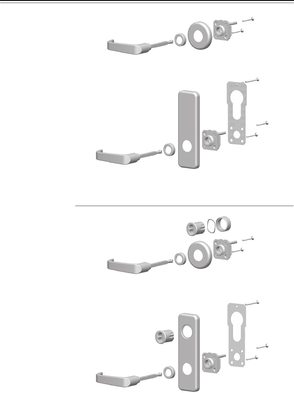
Trim Parts
5–4 40H Series Service Manual
Figure 5.1 OS1 – Outside lever only
Figure 5.2 OS2 – Outside lever & cylinder
1
23
4
1
2
3
4
Sectional trim
Escutcheon trim
6
5
6
7
1
23
4
1
2
3
4
Sectional trim
Escutcheon trim
6
5
6
8
10
7
8
9
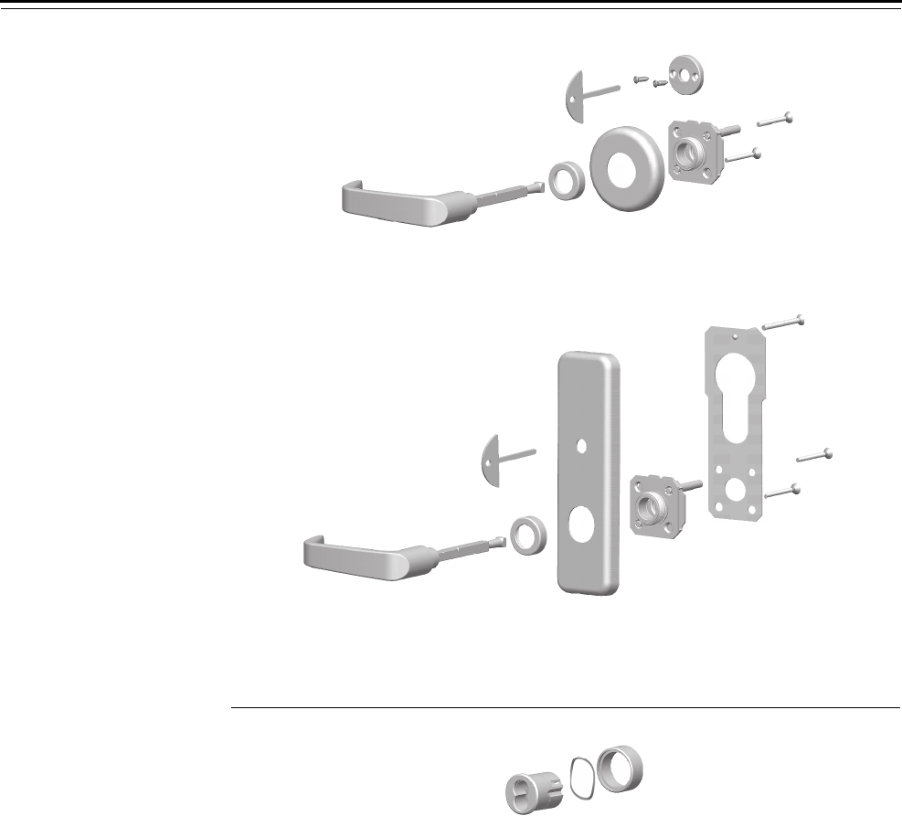
Trim Parts
40H Series Service Manual 5–5
Figure 5.3 OS3 – Outside lever & access plate
Figure 5.4 OS4 – Outside cylinder only
1
23
4
1
2
3
4
Sectional trim
Escutcheon trim
6
5
6
12
13
7
11
11
8
10
All trim
9

Trim Parts
5–6 40H Series Service Manual
INSIDE TRIM KITS
How to order To order inside trim kits, use the nomenclature shown in the example
below.
40HTK – IS1 – 14 – H – 626 –
Series:
40HTK – Trim kit
Kit number:
IS1 – Inside lever only
IS2 – Inside lever & thumb turn
IS31 – Inside lever & cylinder
IS4† – Inside cylinder only
IS5 – Inside thumb turn only
Lever style:
3 – Solid tube / return lever
4 – Round knob
12 – Solid tube / no return lever
14 – Curved return lever
15 – Contour / angle return lever
16 – Curved / no return lever
17LH – Gullwing / no return lever
17RH – Gullwing / no return lever
Trim style:
H – 2 3/4″ diameter rose
J – Stamped escutcheon
M – Forged escutcheon
N – Forged (concealed cylinder) escutcheon
R – 2 3/4″ diameter rose
S – 3 9/16″ diameter rose
Finish:
605 606 611
612 613 618
619 625 626
629 630 690
Options:
Thick door – Specify thickness if other than 1 3/4″2
TL – Tactile lever
SH – Security head screws
1. IS3 and IS4 include the cylinder ring used for double-keyed
applications.
2. For door thickness information, see the table on the next page.

Trim Parts
40H Series Service Manual 5–7
The table below lists available door thicknesses. If a door’s thickness
falls between two thicknesses listed below, round up. For doors where
the mortise case is not centered in the door, contact your local BEST
Representative.
Kit components The components of each inside trim kit are described in the table
below. Figure 5.5 through Figure 5.9 show the components included in
each inside trim kit. A sectional trim example (H style trim) and an
escutcheon trim example (J style trim) are shown for each kit.
Available door thicknesses
2″3 3/4″
2 1/4″4″
2 1/2″4 1/4″
2 3/4″4 1/2″
3″4 3/4″
3 1/4″5″
3 1/2″
Qty. per kit
Item Description IS1 IS2 IS3 IS4 IS5a
a. IS5 is available for sectional trim only.
1 Inside trim mounting plateb
b. To obtain an inside trim mounting plate with a lever spring, use B45071.
To obtain an inside trim mounting plate without a lever spring (used with the #4 knob),
use B45070.
111
2 Rose or inside escutcheon assemblyc
c. For part numbers for roses and rose rings, see page 5–25.
For part numbers for inside escutcheons, see page 5–23.
111
3 Rose / escutcheon ring 111
4Inside lever
d
d. For information to order lever sets, see page 5–13.
111
not shown Socket set screw for lever handlee
e. For information to order screw kits, see page 5–19.
111
5 Thumb turn and rose assemblyf
f. The inside escutcheon assembly for J, M, and N trim includes an integrated thumb turn.
11
6 Thumb turn mounting screw (#6 × 1/2″ POH)d22
7 Cylinder ringg
g. The cylinder ring provided is for double-keyed applications.
11
8Wavy washer 11
9 Cylinder and cam assembly 1 1
not shown Cylinder set screw (#10-24 × .330″)e11
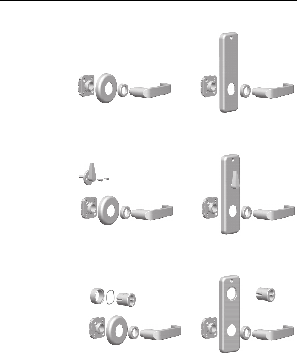
Trim Parts
5–8 40H Series Service Manual
Figure 5.5 IS1 – Inside lever only
Figure 5.6 IS2 – Inside lever & thumb turn
Figure 5.7 IS3 – Inside lever & cylinder
1
2
341
2
34
Sectional trim Escutcheon trim
Sectional trim Escutcheon trim
5
6
1
2
34
1
2
34
5
Sectional trim Escutcheon trim
799
1
2
341
2
34
8

Trim Parts
40H Series Service Manual 5–9
Figure 5.8 IS4 – Inside cylinder only
Figure 5.9 IS5 – Inside thumb turn only
79
All trim
8
Sectional trim
5
6
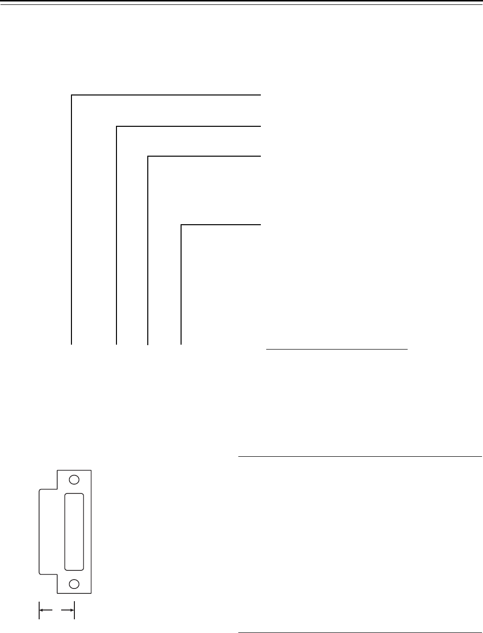
Trim Parts
5–10 40H Series Service Manual
STRIKE PACKAGES
How to order To order strike packages, use the nomenclature shown in the example
below.
The table below lists available door thicknesses (assuming the mortise
case is centered in the door) and indicates the lip to center dimension
of the corresponding strike.
40HST – 1 – 626 –
Series:
40HST – Strike package
Kit number:
1 – Universal strike (non-handed)
4 – Strike box only
5 – Magnetic strike box only
Finish:
605 606 611
612 613 618
619 625 626
629 630 690
Options:
SH – Security head screws
Thick door – Specify thickness if other than 1 3/4″1
7/8-LTC – Flat-lipped strike
1. For door thickness information, see the table below.
Door
thickness
Lip to center
dimension Nomenclature example
2 1/4″1.424″40HST – 1 – 626 – – 2 1/4
2 1/2″1.549″40HST – 1 – 626 – – 2 1/2
2 3/4″1.674″40HST – 1 – 626 – – 2 3/4
3″1.799″40HST – 1 – 626 – – 3
3 1/4″1.924″40HST – 1 – 626 – – 3 1/4
3 1/2″2.049″40HST – 1 – 626 – – 3 1/2
3 3/4″2.174″40HST – 1 – 626 – – 3 3/4
4″2.299″40HST – 1 – 626 – – 4
4 1/4″2.424″40HST – 1 – 626 – – 4 1/4
4 1/2″2.549″40HST – 1 – 626 – – 4 1/2
4 3/4″2.674″40HST – 1 – 626 – – 4 3/4
5″2.799″40HST – 1 – 626 – – 5
Figure 5.10 Lip to center dimension
x
Lip to center dimension—
taken from the edge of the lip to
the center of the screw holes
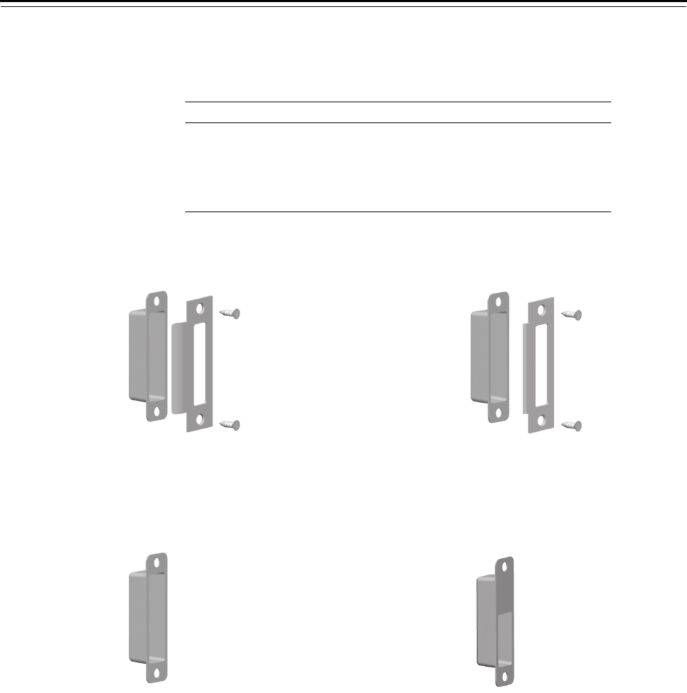
Trim Parts
40H Series Service Manual 5–11
Strike packages The components of each strike package are described in the table
below. Figure 5.11 and Figure 5.13 show the components included in
each strike package.
Qty. per kit
Item Description 1 4 5
1 Universal strike box 1 1
2 40HS1 Universal strike 1
3 Strike screw (#12--12 × 3/4″ PHFH)a
a. For information to order screw kits, see page 5–19.
1
4Magnetic strike box 1
Figure 5.11 Strike kit 1– Universal strike package
123
Figure 5.12 Strike kit 4– Strike box only
1
Figure 5.13 Strike kit 1– Universal strike package
with flat-lipped option
123
Figure 5.14 Strike kit 5– Magnetic strike box only
4

Trim Parts
5–12 40H Series Service Manual
LEVER SETS
How to order To order lever sets, use the nomenclature shown in the example below.
The table below lists available door thicknesses. If a door’s thickness
falls between two thicknesses listed below, round up. For doors where
the mortise case is not centered in the door, contact your local BEST
Representative.
40HLS – 14 – 626 –
S
er
i
es:
40HLS – Lever set
Lever style:1
3 – Solid tube / return lever
4 – Round knob
12 – Solid tube / no return lever
14 – Curved return lever
15 – Contour / angle return lever
16 – Curved / no return lever
17LH – Gullwing / no return lever
17RH – Gullwing / no return lever
Finish:
605 606 611
612 613 618
619 625 626
629 630 690
Options:
Thick door – Specify thickness if other than 1 3/4″2
TL – Tactile lever3
1. For decorative levers see the 40H catalog and the decorative l
e
brochure.
2. For door thickness information, see the table below.
3. The method for achieving a tactile lever can vary depending o
n
lever style and finish.
Available door thicknesses
2″3 3/4″
2 1/4″4″
2 1/2″4 1/4″
2 3/4″4 1/2″
3″4 3/4″
3 1/4″5″
3 1/2″

Trim Parts
40H Series Service Manual 5–13
Lever sets The components of each lever set are described in the table on the next
page. Figure 5.15 through Figure 5.16 show the components included
in each lever set.
Part number
Style Item Description Standard Tactile
3
Solid tube / return lever set
1 Outside lever and spindle assembly B45120aB45121a
2 Inside lever B45110 B44306
not shown Socket set screw for lever handleb
4
Knob set
1 Outside knob and spindle assembly B45180aB45181a
2 Inside knob B45170 B45171
not shown Socket set screw for lever handlea
12
Solid tube / no return
not shown Outside lever and spindle assembly C45423aB44310a
not shown Inside lever C45408 B44311
not shown Socket set screw for lever handlea
14
Curved return lever set
1 Outside lever and spindle assembly B45140aB45141a
2 Inside lever B45130 B45131
not shown Socket set screw for lever handleb
15
Contour / angle return lever set
1 Outside lever and spindle assembly B45160aB45161a
2 Inside lever B45150 B45151
not shown Socket set screw for lever handleb
16
Curve / no return lever set
1 Outside lever and spindle assembly B45182aB45183a
2 Inside lever B45172 B45173
not shown Socket set screw for lever handleb
5 1/8
3
C
L
3/8
3
4 5/16
3 1/4
C
L
2 1/2
4 7/16
2 7/8
C
L
3/8
5 7/32
2 9/16
C
L
3/8
4 3/8
C
L
2
2 7/8

Trim Parts
5–14 40H Series Service Manual
Part number
Style Item Description Standard Tactile
17LH
Gullwing / no return
not shown Outside lever and spindle assembly C45420a
not shown Inside lever C45405
not shown Socket set screw for lever handleb
17RH
Gullwing / no return
not shown Outside lever and spindle assembly C45421a
not shown Inside lever C45406
not shown Socket set screw for lever handleb
a. For part numbers for door thicknesses other than 1 3/4″, contact your local BEST Representative.
b. For information to order screw kits, see page 5–19.
4 5/8
2 3/4
C
L
2 1/2
1 13/16
4 5/8
2 3/4
C
L
2 1/2
1 13/16
Figure 5.15 Solid tube / return (style 3)
Figure 5.16 Knob (style 4)
Figure 5.17 Curved return (style 14)
Figure 5.18 Contour/angle return (style 15)
Figure 5.19 Curve / no return (style 16)
12
1
2
1
2
1
2
1
2
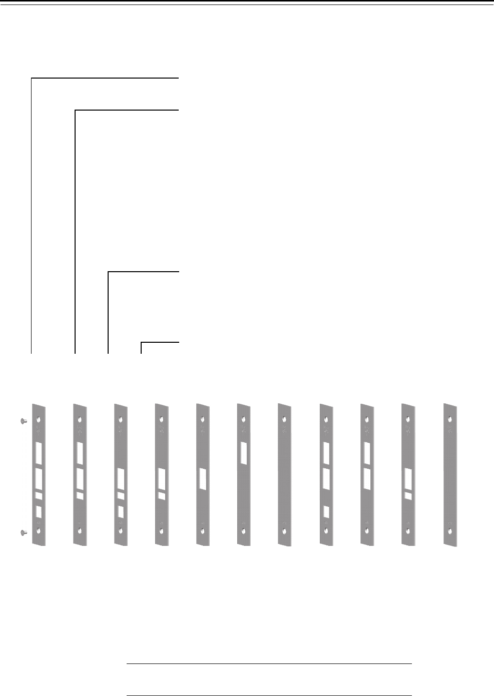
Trim Parts
40H Series Service Manual 5–15
FACEPLATE KITS
How to order To order faceplate trim kits, use the nomenclature shown in the
example below.
Faceplate kits All faceplate kits contain the components listed in the table below.
Figure 5.20 shows the faceplate for each kit.
40HFP – 3 – 626 –
Series:
40HFP – Faceplate kit
Kit number:
0 – AB
1 – BW, H, HJ, LEL, LEU, TD, TDEL, TDEU, TWEL, TWEU
2 – A
3 – AT, C, D, DEL, DEU, INL, NX, NXEU, NXEL, R, W, WEL, WEU
4 – N, LT
5 – AD, WD, YD, RD
6 – Blank with logo
7 – BA, S, TA
8 – B, B5, B7, G, IND, L, LB, T
9 – CHB, RHB
10 – Blank without logo
Finish:
605 606 611
612 613 618
619 625 626
629 630 690
Options:
SH – Security head screws
Figure 5.20 Faceplate kits
12
Kit 0 Kit 1 Kit 2 Kit 3†Kit 4 Kit 5 Kit 6‡Kit 7 Kit 8 Kit 9†Kit 10‡
† The faceplate in Kit 3 has the UL mark. The faceplate in Kit 9 does not have the UL mark.
‡ The faceplate in Kit 6 has the BEST logo. The faceplate in Kit 10 does not have the BEST logo.
Item Description Qty.
1 Faceplate screw (#8-32 × 1/4″ PHFHMS)a
a. For information to order screw kits, see page 5–19.
2
2Faceplate 1

Trim Parts
5–16 40H Series Service Manual
REPLACEMENT SPINDLES
How to order To order replacement spindles, use the nomenclature shown in the
example below.
The table below lists available door thicknesses. If a door’s thickness
falls between two thicknesses listed below, round up. For doors where
the mortise case is not centered in the door, contact your local BEST
Representative.
40HRS – 2 –
Series:
40HRS – Replacement spindle kits
Kit number:
2 – 40H Standard spindle
4 – 40H Hook spindle (1 3/4″ thick door only)
Options:
Thick door – Specify thickness if other than 1 3/4″1
1. For door thickness information, see the table below.
Available door thicknesses
2″3 3/4″
2 1/4″4″
2 1/2″4 1/4″
2 3/4″4 1/2″
3″4 3/4″
3 1/4″5″
3 1/2″
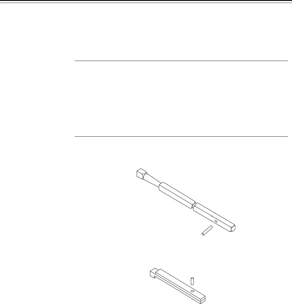
Trim Parts
40H Series Service Manual 5–17
Replacement
spindles
The components of each replacement spindle kit are described in the
table below. Figure 5.20 shows each replacement spindle.
Qty, per kit
Item Description
Part
number
2
(Standard)
4
(Hook)
1 Inside spindle B34016 1
2 Outside spindle B44181 1
3Spring pin (1/8 × 5/8″) A63101 1
not shown Socket set screw for lever handlea
a. For information to order screw kits, see page 5–19.
1
not shown Allen wrench (1/8″)b
b. For information to order an allen wrench, see page 5–29
1
4 Lower hook spindle A34205 1
5 Upper hook spindle A34204 1
6Pin (1/8 × 0.215″) A34203 1
Figure 5.21 Spindle kit 2 – Standard replacement spindle
Figure 5.22 Spindle kit 4 – Hook replacement spindle
3
1
2
6
5
4

Trim Parts
5–18 40H Series Service Manual
SCREW KITS
How to order To order screw kits, use the nomenclature shown in the example
below.
The table below lists available door thicknesses. If a door’s thickness
falls between two thicknesses listed below, round up. For doors where
the mortise case is not centered in the door, contact your local BEST
Representative.
40HSK – 1 – 626 –
Series:
40HSK – Screw kits
Kit number:
1 – H, R, S, J trim screw kit
2 – M, N trim screw kit
3 – Special purpose fasteners screw kit
4 – Surface-mounted trim screw kit
5 – Visual indicator screw kit
Finish:
606 612
613 626
Options:
Thick door – Specify thickness if other than 1 3/4″1
SH – Security head screws
1. For door thickness information, see the table below.
Available door thicknesses
2″3 3/4″
2 1/4″4″
2 1/2″4 1/4″
2 3/4″4 1/2″
3″4 3/4″
3 1/4″5″
3 1/2″
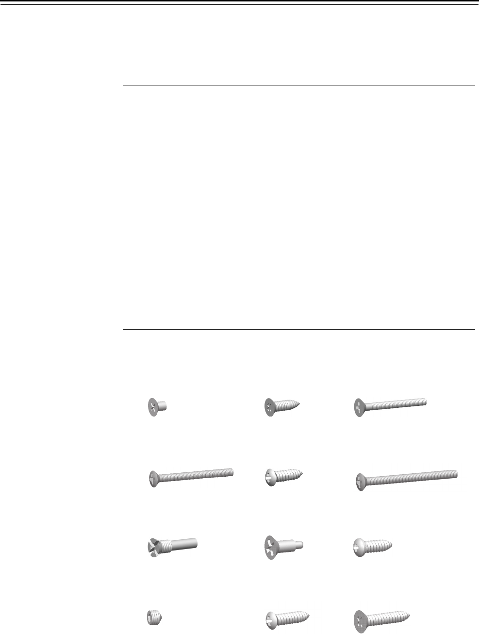
Trim Parts
40H Series Service Manual 5–19
Screw kits The components of screw kits are described in the table below.
Figure 5.23 shows the components included in each screw kit.
Qty. per kit
ItemDescription 12345
1 Faceplate screw (#8-32 × 1/4″ PHFHMS)a
a. Security head option accepts T15 bit.
22
2 Strike screw / case mounting screw
(#12-12 × 3/4″ PHFH)b
b. Security head option accepts T25 bit.
44
3 Trim plate mounting screw (#8-32 UNC-2A)c
c. When the thick door option is selected, a longer screw is provided.
22
4J alignment plate mounting screw
(#8-32 × 1.75″ UNC-2A POHMS)a, c 1
5 Thumb turn mounting / emergency access
plate screw (#6 × 1/2″ POH)
2
6M/N escutcheon screw (#10-32 × 2 1/8″)b, c 2
7 Shuttle guide pin 2
8 Hub toggle screw 2
9 Self tapping screw (TD, HJ, BW functions) /
Visual indicator bracket mounting screw
12
10 Socket set screw for lever handled
d. Security head option accepts spanner head bit.
1
11 Upper J escutcheon screw
(#6 × 5/8″ POH surface mounting)
1
12 Single dummy trim mounting screw
(#8 × 1″ PFH surface mounting)
2
Figure 5.23 Screw kit components
123
45
7
6
8
12
11
9
10

Trim Parts
5–20 40H Series Service Manual
CYLINDERS AND CAMS
How to order To order a cylinder and cam assembly and cylinder ring for a 40H Series
Lock with sectional trim, J trim, or M trim, use the nomenclature shown
in the example below. For information for ordering a cylinder and cam
assembly and cylinder ring for a 40H Series Lock with N trim or a hotel
function, see the tables on the next page.
1E74 – 24 – C258 – B35103 – 626
Series:
1E74 – Standard mortise cylinder
Door thickness:
– Standard (1 3/4″)
24 – 2″34 – 3 1/4″44 – 4 1/2″
26 – 2 1/4″36 – 3 1/2″48 – 4 3/4″
28 – 2 1/2″40 – 3 3/4″48 – 5″
32 – 2 3/4″40 – 4″
32 – 3″44 – 4 1/4″
Cam:
C258 – Standard mortise cam1
C293 – Cam for C and CHB outside cylinder
Ring:
B35103 – Single cylinder ring assembly (H or R trim)
B35105 – Double cylinder ring assembly (H or R trim)
Finish:
605 606 611
612 613 618
619 625 626
629 630 690
1. The turn knob cylinder for the RD function (classroom
deadbolt) has specialized components and must be ordered
with the lock.
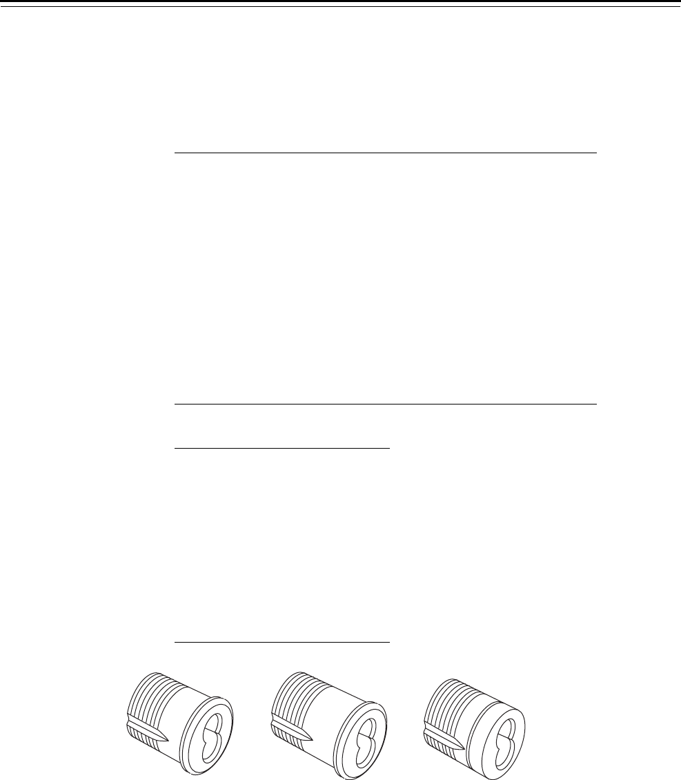
Trim Parts
40H Series Service Manual 5–21
Cylinders by door
thickness
The table below lists cylinders by door thicknesses. If a door’s thickness
falls between two thicknesses listed below, round up. For doors where
the mortise case is not centered in the door, contact your local BEST
Representative.
Cylinder ring
lengths
Door thickness
Sectional, J, and
M cylinder Hotel cylinder N cylinder
2″B35170 B35200 1E7N4
2 1/4″B35171 B35201 B35284
2 1/2″B35172 B35202 B35285
2 3/4″B35173 B35203 B35286
3″B35174 B35204 B35287
3 1/4″B35175 B35205 B35288
3 1/2″B35176 B35206 B35289
3 3/4″B35177 B35207 B35290
4″B35178 B35208 B35291
4 1/4″B35179 B35209 B35292
4 1/2″B35180 B35210 B35293
4 3/4″B35181 B35211 B35294
5″B35182 B35212 B35295
Ring part no. Length (decimal)
B35100 7/32″(.219)
B35101 11/32″(.344)
B35102 13/32″(.406)
B35103 7/16″(.438)
B35104 9/16″(.562)
B35105 19/32″(.594)
B35106 21/32″(.656)
B35107 23/32″(.719)
B35108 13/16″(.812)
B35109 5/16″(.312)
Figure 5.24 Cylinders
Standard cylinder Hotel cylinder N trim cylinder
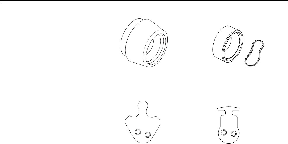
Trim Parts
5–22 40H Series Service Manual
Figure 5.25 Cylinder rings
Cylinder ring Wavy washer
High security cylinder ring
Figure 5.26 Cylinder cams
Standard cam (C258) Cam for CHB & RHB
O/S cylinder (C293)
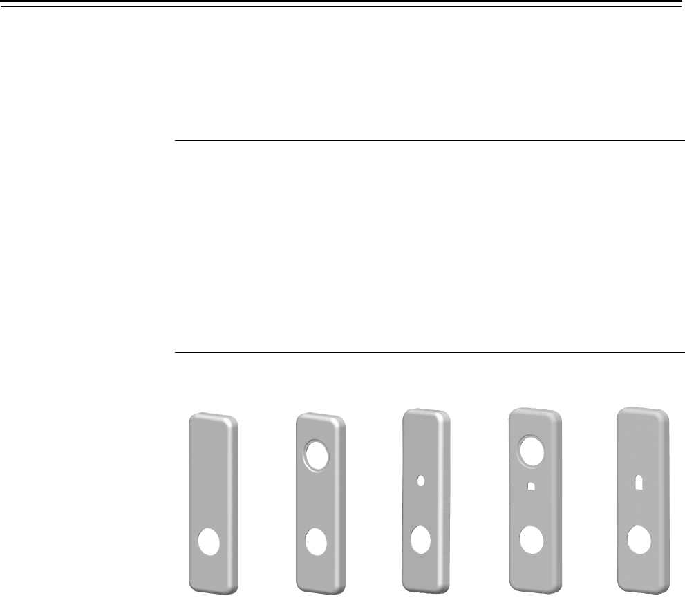
Trim Parts
40H Series Service Manual 5–23
ESCUTCHEON ASSEMBLIES
J trim outside
escutcheons
J trim outside escutcheon assemblies are described in the table and
figures below.
Item Description Functions Part number
1Outside escutcheon LEL, LEU N, NX, NXEL, NXEU C44091
2Outside escutcheon A, AB, AT, B, BA, BW, B5, B7, C,
CHB, D, DEL, DEU, G, HJ, IND,
INL, R, RHB, S, T, TA, TD, TDEL,
TDEU, TWEL, TWEU, W, WEL,
WEU
C44092
3Outside escutcheon L, LB, LT C44093
4Outside escutcheon for keyed
visual indicator
H, HJ a
a. The keyed visual indicator may also be used with IND, INL, and TD function locks.
D44094
5Outside escutcheon for
privacy visual indicator (with
emergency key)
L, LB, LT D44095
Figure 5.27 Outside J trim escutcheons
1234 5
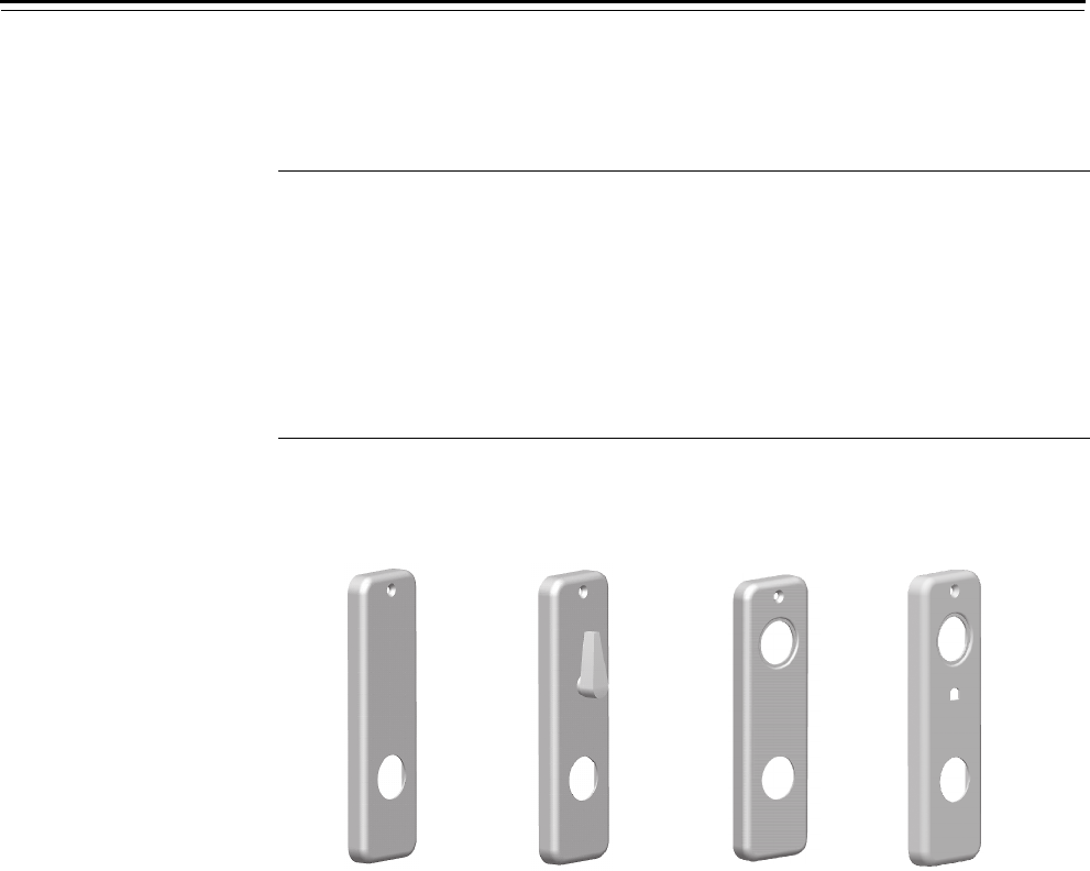
Trim Parts
5–24 40H Series Service Manual
J trim inside
escutcheons
J trim inside escutcheon assemblies are described in the table and
figures below.
Item Description Functions Part number
1 Inside escutcheon A, B5, D, DEL, DEU, N, NX,
NXEL, NXEU, R, RHB, TDEL,
TDEU
D44081
2 Inside escutcheon and turn
knob assembly
AB, AT, B, BA, BW, H, HJ, L,
LB, LEL, LEU, LT, T, TA, TD
B45200a
a. For part numbers for door thicknesses other than 1 3/4″, contact your local BEST
Representative.
3 Inside escutcheon B7, C, CHB, G, IND, INL, S,
TWEL, TWEU, W, WEL, WEU
D44082
4 Inside escutcheon for keyed
visual indicator
INL, IND D44084
Figure 5.28 Inside J trim escutcheons
12 34

Trim Parts
40H Series Service Manual 5–25
M & N trim outside
escutcheons
M and N trim outside escutcheon assemblies are described in the table
and figures below.
Item Description Functions Part number
1 M trim outside blank escutcheon For lever one side only applications C44451
2 M trim outside escutcheon for 45H For lever only applications C44452
3 M trim outside escutcheon for 45H XR C44453
4 M trim outside escutcheon for 45H A, AB, AT, B, BA, BW, B5, B7, C, CHB, D,
DEL, DEU, G, HJ, IND, INL, R, RHB, S, T, TA,
TD, TDEL, TDEU, TWEL, TWEU, W, WEL,
WEU
C44454
5 M trim outside escutcheon for 45H L, LB, LT C44455
6 M trim outside escutcheon for 47H XR B45221a
7 M trim outside escutcheon for 47H A, AB, AT, B, BA, BW, B5, B7, C, CHB, D,
DEL, DEU, G, HJ, IND, INL, R, RHB, S, T, TA,
TD, TDEL, TDEU, W, WEL, WEU
B45222a
8 N trim outside escutcheon for 45H XR C44458
9 N trim outside escutcheon for 45H A, AB, AT, B, B5, B7, D, DEL, DEU, G, IND,
INL, R, RHB, S, T, TA, TD, TDEL, TDEU, W,
WEL, WEU
C44459
a. These escutcheon assemblies include the hardened security plate (A34377).
Figure 5.29 Outside M & N trim escutcheons
12
769
3 4
5 8
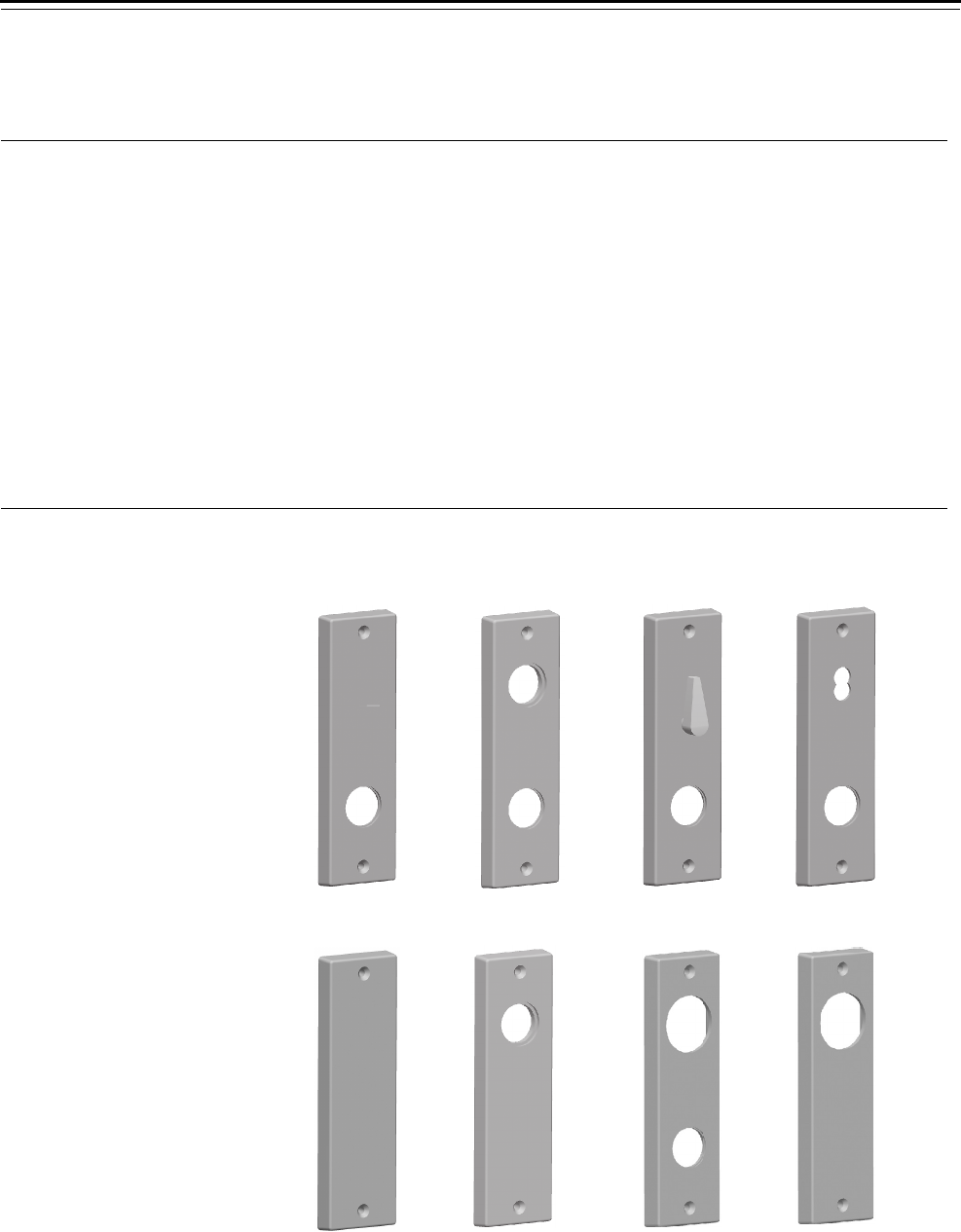
Trim Parts
5–26 40H Series Service Manual
M & N trim inside
escutcheons
M and N trim inside escutcheon assemblies are described in the table
and figures below.
Item Description Functions Part number
1 M & N trim inside escutcheon for 45H A, AT, B5, B7, D, DEL, DEU, NXEL, NXEU, R,
RHB, TDEL, TDEU, XR
C44462
2 M trim inside escutcheon for 45H C, CHB, G, IND, INL, S, TWEL, TWEU, W,
WEL, WEU
C44464
3 M & N trim inside escutcheon for 45H AB, B, BA, BW, LEL, LEU, TA, TD B45210a
4 N trim inside escutcheon for 45H CHB, G, IND, INL, S, TWEL, TWEU, W, WEL,
WEU
C44469
5 M trim inside blank escutcheon for 45H For lever one side only applications D44461
6 M trim inside escutcheon for 45H For lever one side only applications with
only a cylinder on the inside
C44463
7 M trim inside escutcheon for 47H C, CHB, G, IND, INL, S, TWEL, TWEU, W,
WEL, WEU
B45223b
8 M trim inside escutcheon for 47H For lever one side only applications with
only a cylinder on the inside
B45220b
a. For part numbers for door thicknesses other than 1 3/4″, contact your local BEST Representative.
b. These escutcheon assemblies include the hardened security plate (A34377).
Figure 5.30 Inside M & N trim escutcheons
1234
6
58
7
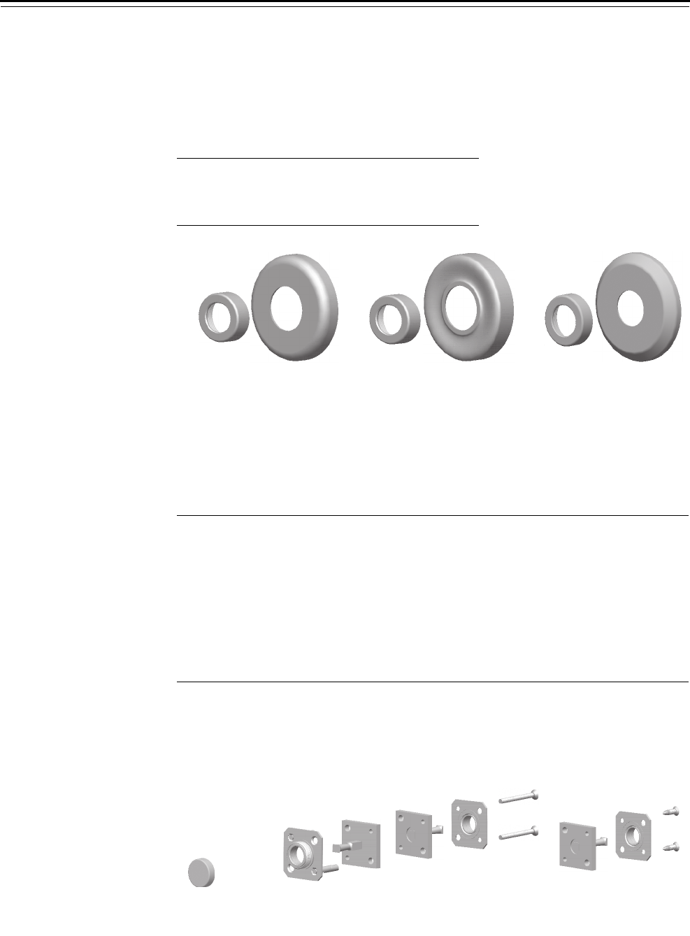
Trim Parts
40H Series Service Manual 5–27
ROSES AND ROSE RINGS
Rose and rose ring components are described in the table and figure
below.
DUMMY TRIM
Dummy trim parts are described in the table and figures below.
Part number
Item Description Rose Ring
1 H trim A44070 B44182
2 R trim A44074 B44182
3 S trim A44080 B44182
Figure 5.31 Roses & rose rings
12 3
Item Description Part number 1DT (qty.) 2DT (qty.)
1 Dummy trim rose ringa
a. Used with double dummy trim for single dummy trim applications.
B44183
2 Outside trim mounting plate B35027 1
3 Dummy trim assembly A45050 1 2
4 Inside trim mounting plate A35028 1 1
5 40H Trim cassette mounting screw
(for 1 3/4″ to 2 1/4″ thick doors)
A44215b
b. For part numbers for door thicknesses other than 1 3/4″, contact your local BEST
Representative.
2
6 Single dummy trim mounting screw
(#8 × 1″ PFH surface mounting)c
c. For information to order screw kits, see page 5–19.
A39217 2
Figure 5.32 Dummy trim parts
Single dummy trim
3
4
2
5
3
Double dummy trim
346
1
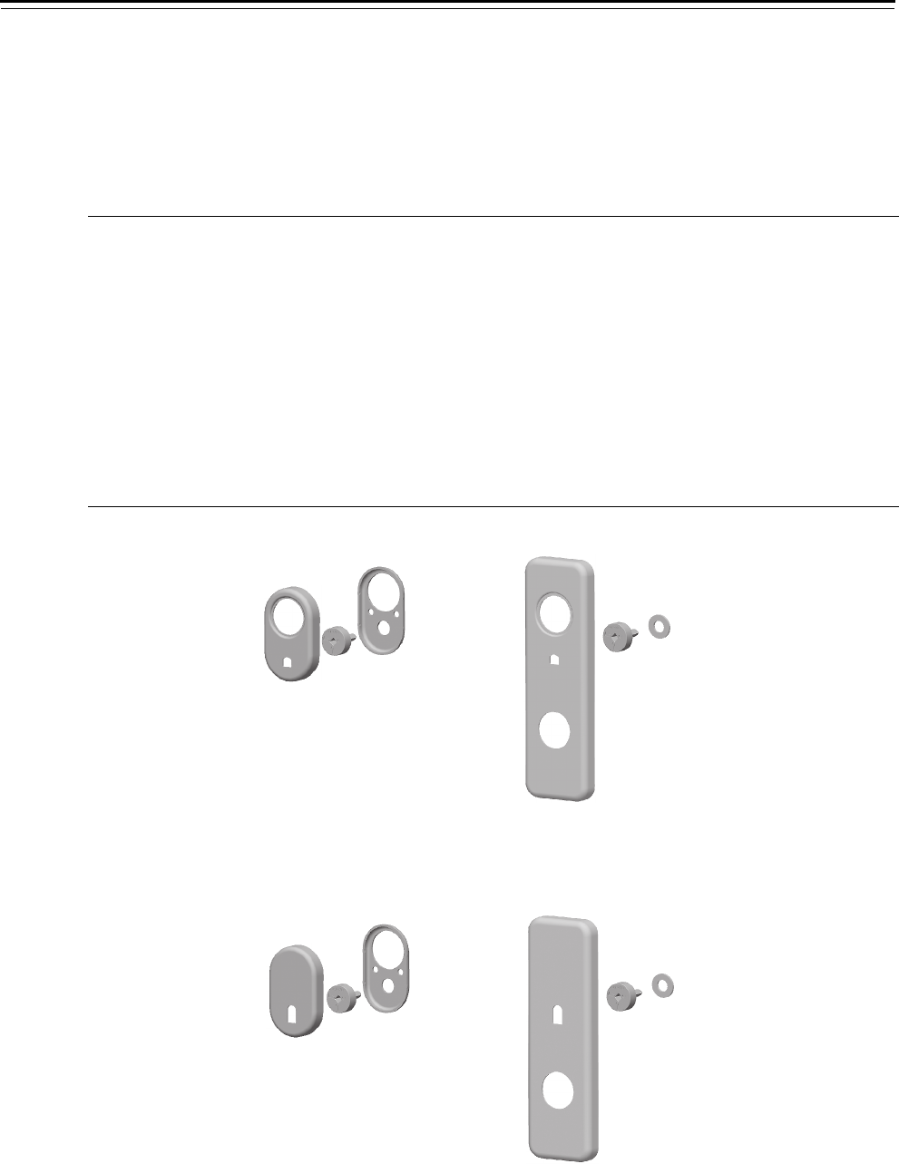
Trim Parts
5–28 40H Series Service Manual
VISUAL INDICATOR TRIM
The table below lists visual indicator trim components. Sectional trim
and J style trim are shown below. Visual indicator trim is not available
for M & N trim.
Item Description
Part
number
Sectional
trim (qty.)
J trim
(qty.)
1 Keyed visual indicator cover B44510 1
2 Visual indicator dial assembly (deadbolt) A45053 1 1
not shown Visual indicator dial assembly (latchbolt) A45052 1 1
not shown Visual indicator bracket mounting screwa2
3 Visual indicator mounting bracket B44512 1
4 J trim outside escutcheon for keyed visual indicator D44094 1
not shown J trim inside escutcheon for keyed visual indicator D44084 1
5 J trim escutcheon cam spacer B44515 1
6 Privacy visual indicator cover B44511 1
7 J trim outside escutcheon for privacy visual indicator D44095 1
a. For information to order screw kits, see page 5–19.
Figure 5.33 Keyed visual indicator trim
Figure 5.34 Privacy visual indicator trim
Sectional trim J trim
3
4
25
1
2
Sectional trim J trim
6
7
3
25
2
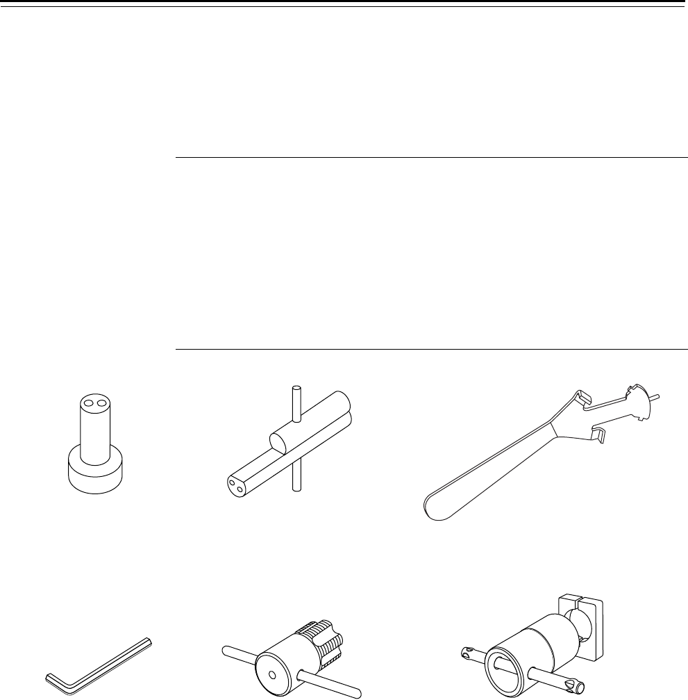
Trim Parts
40H Series Service Manual 5–29
SERVICE EQUIPMENT
Tools for use with 40H Series Locks are described in the table and figure
below.
Item
Nomen-
clature Description Used for
1 ED212 Mortise cylinder cam
assembly tool
Tool for assembling cams to mortise
cylinders
2 ED211 Cylinder wrench Tool for installing, removing, and testing
cylinders
3 KD316 Spanner wrench Tool for installing sectional trim
4 1233659 Allen wrench (1/8″) Tool for installing and removing the
inside lever
5 ED225 Cylinder tap Tool for rethreading case threads
6 ED221 Cylinder die Tool for rethreading 1 5/32″ diameter
cylinders
Figure 5.35 Service equipment
12 3
564
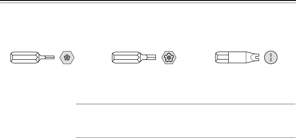
Trim Parts
5–30 40H Series Service Manual
DRIVER BITS
Special driver bits for security head screws are described in the table
and figure below.
Figure 5.36 Driver bits
TORX T15 TORX T25 Spanner head
Type Part number Used for
TORX T15a
a. TORX is a registered trademark of the Camcar Division of Textron.
A34457 Security head trim mounting screw, thumb turn
mounting screw, faceplate screw
TORX T25 A34458 Security head case mounting screw, strike screw
Spanner head A34407 Lever set screw
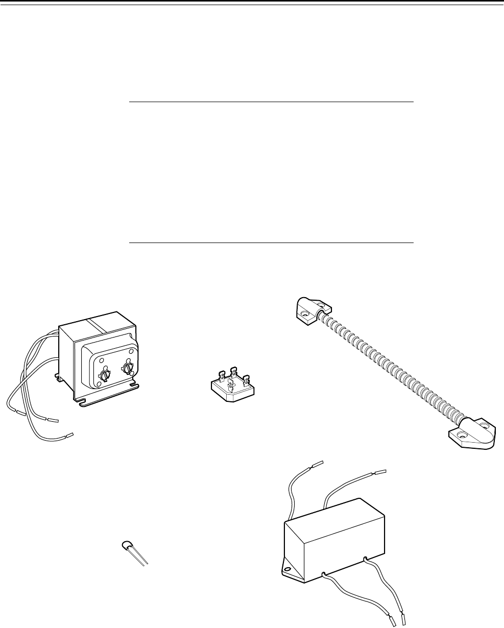
Trim Parts
40H Series Service Manual 5–31
ACCESSORIES FOR ELECTRIFIED LOCKS
Accessories for use with 45HW & 47HW Series Electrified Mortise Locks
are described in the table and figure below.
Item Nomenclature Description
1 8W599 Transformer (converts 120 volts AC
to 24 volts AC)
2 8WCON AC to DC converter
full wave bridge rectifier
38WDTL Door transfer loop
48WMOV Metal oxide varistor
5 8WTCM Temperature control module
not shown CECB 179-66
CECB 168-66
CECB 191-66
Electrified hingea
a. BEST recommends one of the listed concealed electric hinges from Stanley
Security Solutions. For more information, contact your BEST representative.
Figure 5.37 Accessories for electrified locks
12 3
54

Trim Parts
5–32 40H Series Service Manual

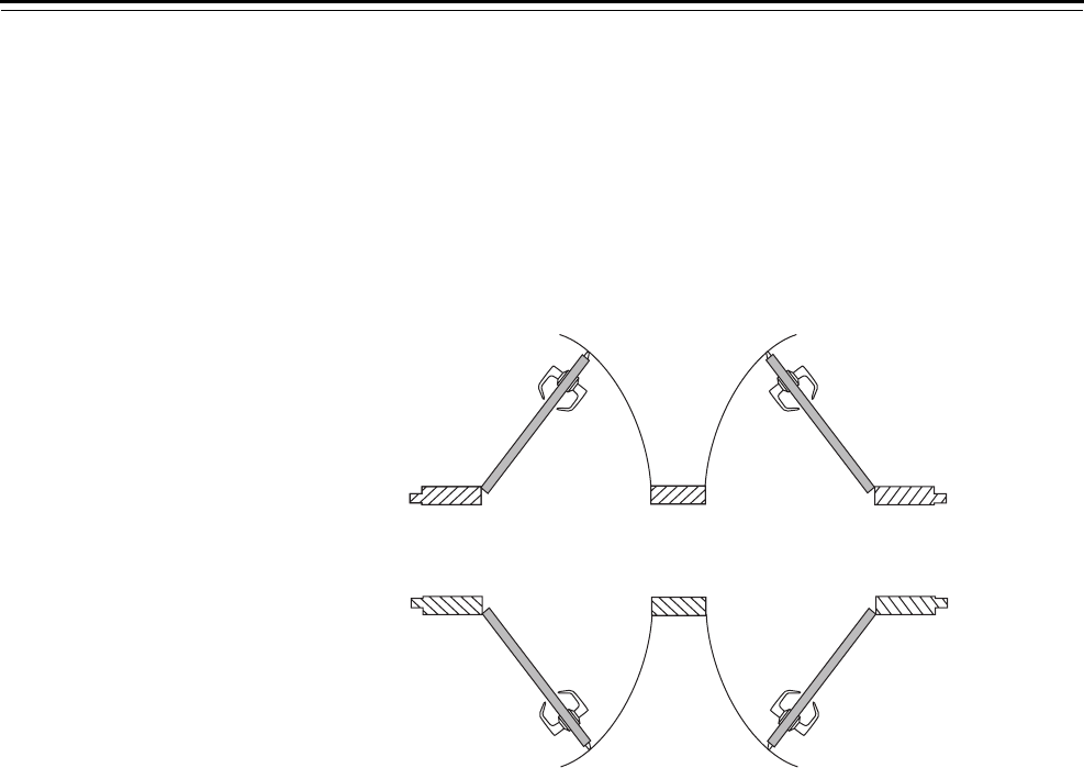
Service and Maintenance
6–2 40H Series Service Manual
CHANGING THE HAND
This section describes how to change the hand and/or bevel of the
45H , 47H, 45HW & 47HW mortise case. The section includes a quick
reference and instructions.
Changing hand
quick reference
Review the diagram below to understand the hand and bevel of the
door.
Changing handing
for the mortise case
The handing of a 45H & 47H mortise case or 45HW & 47HW mortise
case can be changed without opening the case. To change the hand,
you need to rotate the latchbolt. For all lock functions except W and N,
you also need to adjust the hub toggle positions. No steps are required
for adjusting the bevel since the armored front on the 45H & 47H
mortise case automatically adjusts to the bevel of the door when the
case is installed.
To rotate the latchbolt:
1. Confirm that you need to rotate the latchbolt to match the handing
of the door.
Note: The angled surface of the latchbolt must contact the strike
when the door closes.
2. To rotate the latchbolt, insert a flat blade screwdriver into the latch
access point approximately 1/2″ into the case and press to extend
the latch out of the case. See Figure 6.2.
3. Rotate the latchbolt 180 degrees and allow it to retract.
Figure 6.1 Explanation of the hand and bevel of the door
Outside
Outside
Left hand (LH) Right hand (RH)
Right hand reverse bevel (RHRB)Left hand reverse bevel (LHRB)
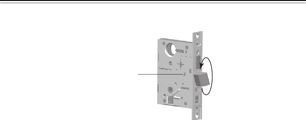
Service and Maintenance
40H Series Service Manual 6–3
To change the position of the hub toggles:
1. Refer to the table below and determine the proper position for the
hub toggles.
Note: For LH and LHRB doors, the inside is the back side of the case
and the outside is the cover side of the case. For RH and RHRB
doors, the inside is the cover side of the case and the outside is the
back side of the case.
2. To change the position of a hub toggle, remove the toggle screw,
move the toggle into the desired position, and re-tighten the screw.
See Figure 6.3.
Figure 6.2 Rotating the latchbolt
Latch access point
Function Hub toggle position
A, AB, AT, C, CHB, D, DEL, DEU, H, HJ, IND,
INL, L, LEL, LEU, LT, NX, NXEL, NXEU, R, RHB,
T, TA, TD, TDEL, TDEU, TWEL, TWEU, WEL,
WEU, XR, ZD
Inside down (always unlocked) &
outside up (lockable)
B, BA, BW, B5, B7, G, LB, S, W Both up
NBoth down
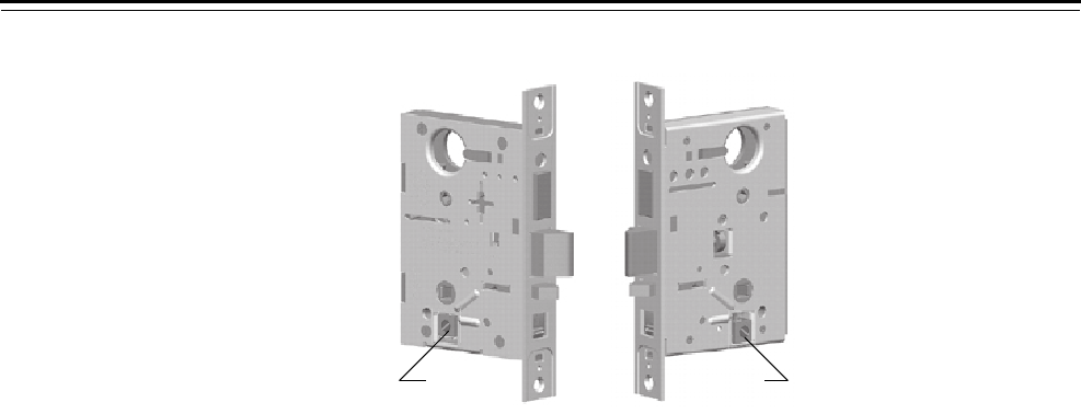
Service and Maintenance
6–4 40H Series Service Manual
Figure 6.3 Positioning the hub toggles
Hub toggleHub toggle

Service and Maintenance
40H Series Service Manual 6–5
CHANGING THE FUNCTION FOR UNIVERSAL CASES
This section provides instructions for changing the function for the
45H & 47H universal mortise cases (UNR, UNAB, and UNT). For
information about which inside and outside trim kits to use with each
function, see Working with trim kits on page 2-3.
Changing the
function for
UNR cases
The UNR mortise case can be configured for any of the following
functions:
■A
■AT
■D
■INL
■N
■NX
■R
To convert the UNR case from one function to another, you need to
adjust the shuttle screw positions and possibly the hub toggle positions.
To adjust the shuttle screw positions:
Refer to the table and guidelines below. Also, see Figure 6.4.
Note: To position the shuttle, insert a screwdriver into the opening for
the thumb turn hub and rotate the shuttle.
■For an N function, position the shuttle towards the face of the case
and move the shuttle screw from position 0, 2, or 3 to position 1. If
converting from an A function configuration, move the shuttle screw
from position 4 to position 5.
■For a D, NX, or W function, position the shuttle towards the back
edge of the case and move the shuttle screw from position 0, 1, or 2
to position 3. If converting from an A function configuration, move
the shuttle screw from position 4 to position 5.
■For an A function, position the shuttle in the middle of the case and
move the shuttle screw from position 0, 1, 2, or 3 to position 4.
Then move the shuttle screw from position 5 to position 2.
Function Shuttle screw positions
A2 & 4
AT, INL, R 0 & 5
D, NX, W 3 & 5
N1 & 5
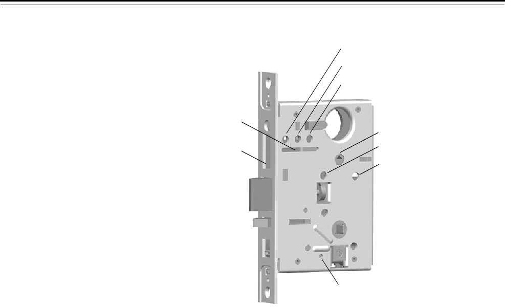
Service and Maintenance
6–6 40H Series Service Manual
To change the position of the hub toggles:
See To change the position of the hub toggles: on page 6–3.
Changing the
function for
UNAB cases
The UNAB mortise case can be configured for any of the following
functions:
■AB
■TA
■TD
When converting from a TA or AB function configuration to a TD
function configuration, install the self-tapping stop screw. See
Figure 6.4.
When converting from a TD function configuration to a TA or AB
function configuration, remove the stop screw. See Figure 6.4.
Changing the
function for
UNT cases
The UNT mortise case can be configured for either the L or T function.
No change to the mortise case is required when changing between
these functions; only trim changes are required.
Figure 6.4 Positioning the shuttle screws and stop screw
Position 0
(storage)
Position 1
Position 2
Position 3
Position 4
Position 5
Stop screw
(for deadbolt functions
with fixed outside lever)
Thumb turn hub
Shuttle

Service and Maintenance
40H Series Service Manual 6–7
TROUBLESHOOTING
This table summarizes the possible causes for certain lock problems.
For problems with the core and key, such as difficulty removing or
inserting the key or difficulty turning the key, see the Core and Key
Service Manual.
You notice… Possible causes include… You should…
Knobs or levers won’t turn. a. Spindle is not backed off. a. Unscrew the inside spindle
one full turn to allow the spindle
to turn freely.
b. Trim is out of alignment. b. Loosen the trim and realign it so
that the deadbolt does not bind.
Inside knob or lever does not remain
unlocked.
Handing is reversed. Change the handing (pg. 6-2).
Outside knob or lever won’t lock. Handing is reversed. Change the handing (pg. 6-2).
Outside knob or lever droops. Spindle has been twisted. Replace the spindle (pg. 5-16).
Key will not operate latch or
deadbolt.
a. Incorrect cam has been installed. a. Install cylinder with proper cam
(pg. 5-20).
b. Cam has fallen to an inverted
position.
b. Rotate the cam to the home
position with a mortise wrench
before installing the core.
Core will not install. Cam has fallen to an inverted
position.
Rotate the cam to the home position
with a mortise wrench before
installing the core.
Deadbolt will not or is difficult to
retract or extend.
Trim is out of alignment. Loosen the trim and realign it so that
the deadbolt does not bind.
Deadbolt on deadbolt-only function
will not extend.
Lock was ordered as an RD function. Check the part nomenclature and
ensure the RD function is needed for
the application.
Deadbolt on deadbolt-only function
will not retract.
Handing has been ordered
incorrectly.
Check to ensure the case and thumb
turn cylinder are the correct
handing for the door. If not, order
the correct case and thumb turn
cylinder.
Lock does not function properly. Universal case is incorrectly
configured.
Configure the case to the desired
function (pg. 6-5).

Service and Maintenance
6–8 40H Series Service Manual

40H Series Service Manual 7–1
7 48H & 49H LOCKS
The following pages contain information about
48H & 49H Lock parts and maintenance.
FUNCTION QUICK REFERENCE
48H / 49H
Functions
Description
page number
Diagram
page number
K See page 7–2 See page 7–3
L See page 7–2 See page 7–3
M See page 7–2 See page 7–3
R See page 7–2 See page 7–4
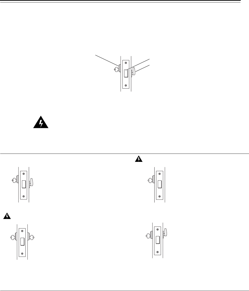
48H & 49H Locks
7–2 40H Series Service Manual
FUNCTION DESCRIPTIONS
The following lists describe how the deadbolt operates for 48H &
49H cylinder deadlock functions. When ordering a deadlock, specify
the handing of the door.
Warning!
Locks that secure both sides of the door are controlled by
building codes and the Life Safety Code. In an emergency exit
situation, failure to quickly unlock the door could be hazardous
or even fatal.
48H & 49H MORTISE CASE PARTS
The following pages contain exploded diagrams and parts lists for
48H & 49H mortise cases.
Figure 7.1 Understanding function drawings
Outside Inside
Deadbolt
Thumb turn
Keyed cylinder
K–Cylinder deadlock L–Cylinder deadlock
Deadbolt operated by:
■inside thumb turn
■outside key
Deadbolt operated by:
■outside key
M–Cylinder deadlock R–Cylinder deadlock
Deadbolt operated by:
■inside or outside key
Deadbolt operated by:
■outside key
■inside thumb turn
Note 1: Specify the hand of the door.
Note 2: Inside turn knob retracts the deadbolt, but
does not project it.
Note 3: Can be used on 1 3/4″ thick doors only.
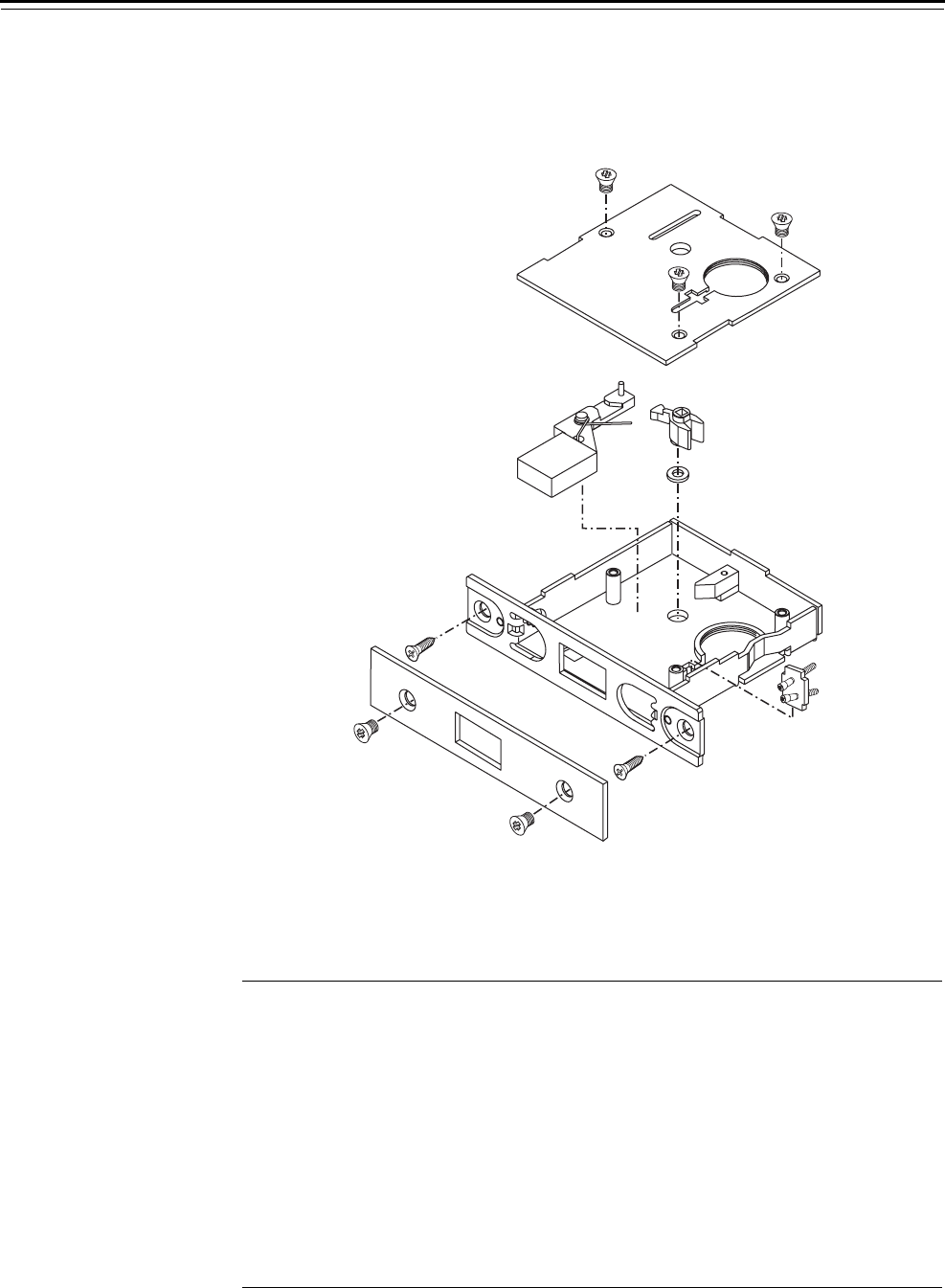
48H & 49H Locks
40H Series Service Manual 7–3
KFUNCTION CASE—CYLINDER DEADLOCK
LFUNCTION CASE—CYLINDER DEADLOCK
MFUNCTION CASE—CYLINDER DEADLOCK
K, L, M function
parts list
Refer to Figure 7.2 and the table below to find the part you need.
Figure 7.2 K, L, M function case
2
8
10
5
3
4
1
7
96
Item Part No.a
a. For a complete case, use B35403.
Qty. Description
1 A34087 3 Case cover mounting screw
2 C34351 1 Cover
3 C34011 1 Turn knob hub
4 A34194 1 Turn knob hub spacer
5 A35022 1 Double cylinder clamp plate
6 B35402 1 Case sub-assembly
7 A18724 2 Case mounting screw (#12-12 × 3/4″ PHFH)
8 B34353 1 Faceplate
9 A18722 2 Faceplate screw (#8-32 × 1/4″ PHFHMS)
10 B35399 1 Deadbolt
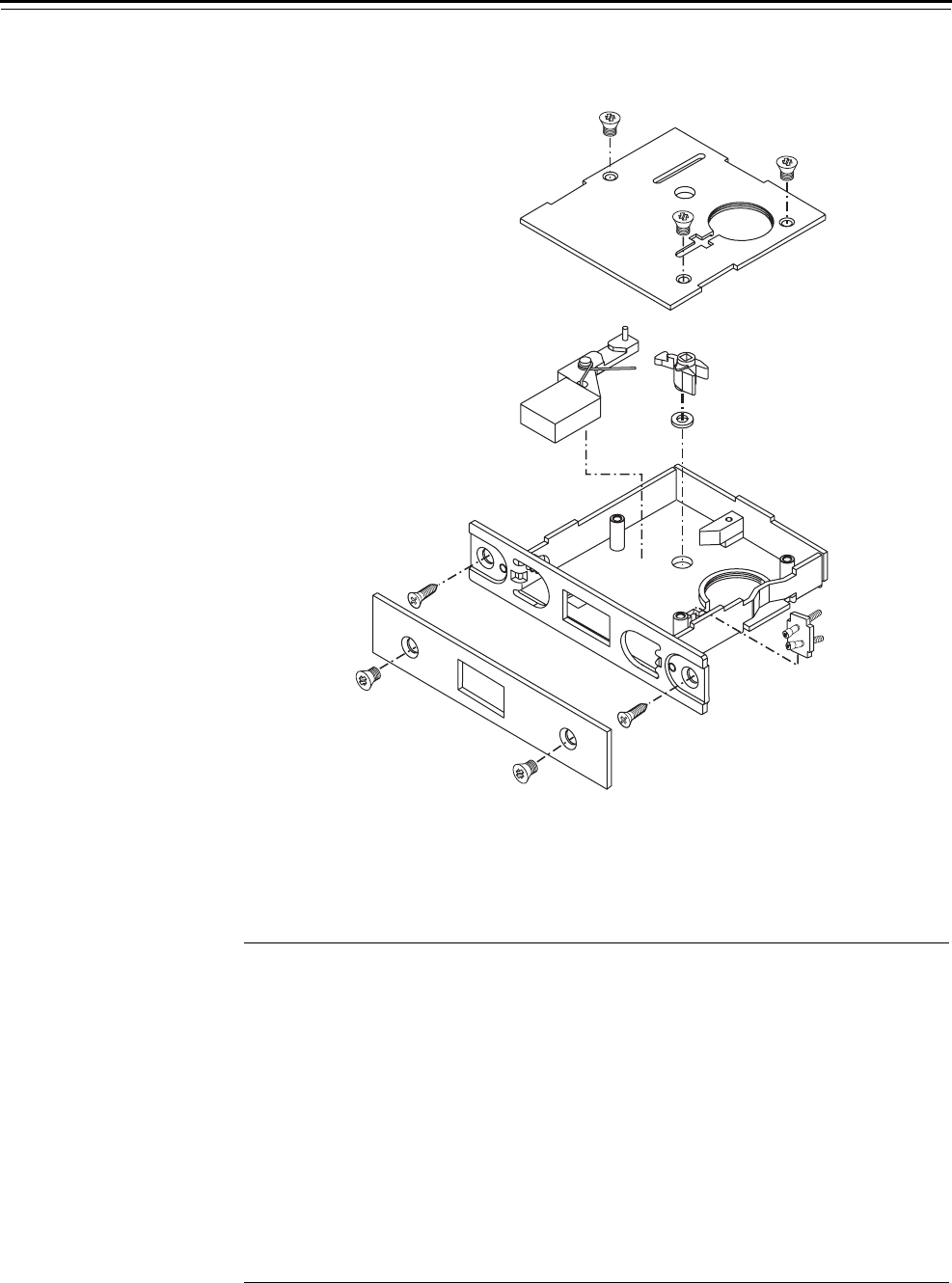
48H & 49H Locks
7–4 40H Series Service Manual
RFUNCTION CASE—CLASSROOM DEADLOCK
R function parts list Refer to Figure 7.3 and the table below to find the part you need.
Figure 7.3 R function case
2
8
10
5
3
4
1
7
96
Item Part No.a
a. For a complete LH case, use C45524. For a complete RH case, use C45525.
Qty. Description
1 A34087 3 Case cover mounting screw
2 C34351 1 Cover
3 A63001 1 “R” turn knob hub (left hand)
not shown A63002 1 “R” turn knob hub (right hand)
4 A34194 1 Turn hub spacer
5 A35022 1 Double cylinder clamp plate
6 B35402 1 Case sub-assembly
7 A18724 2 Case mounting screw (#12-12 × 3/4″ PHFH)
8 B34353 1 Faceplate
9 A18722 2 Faceplate screw (#8-32 × 1/4″ PHFHMS)
10 B35399 1 Deadbolt
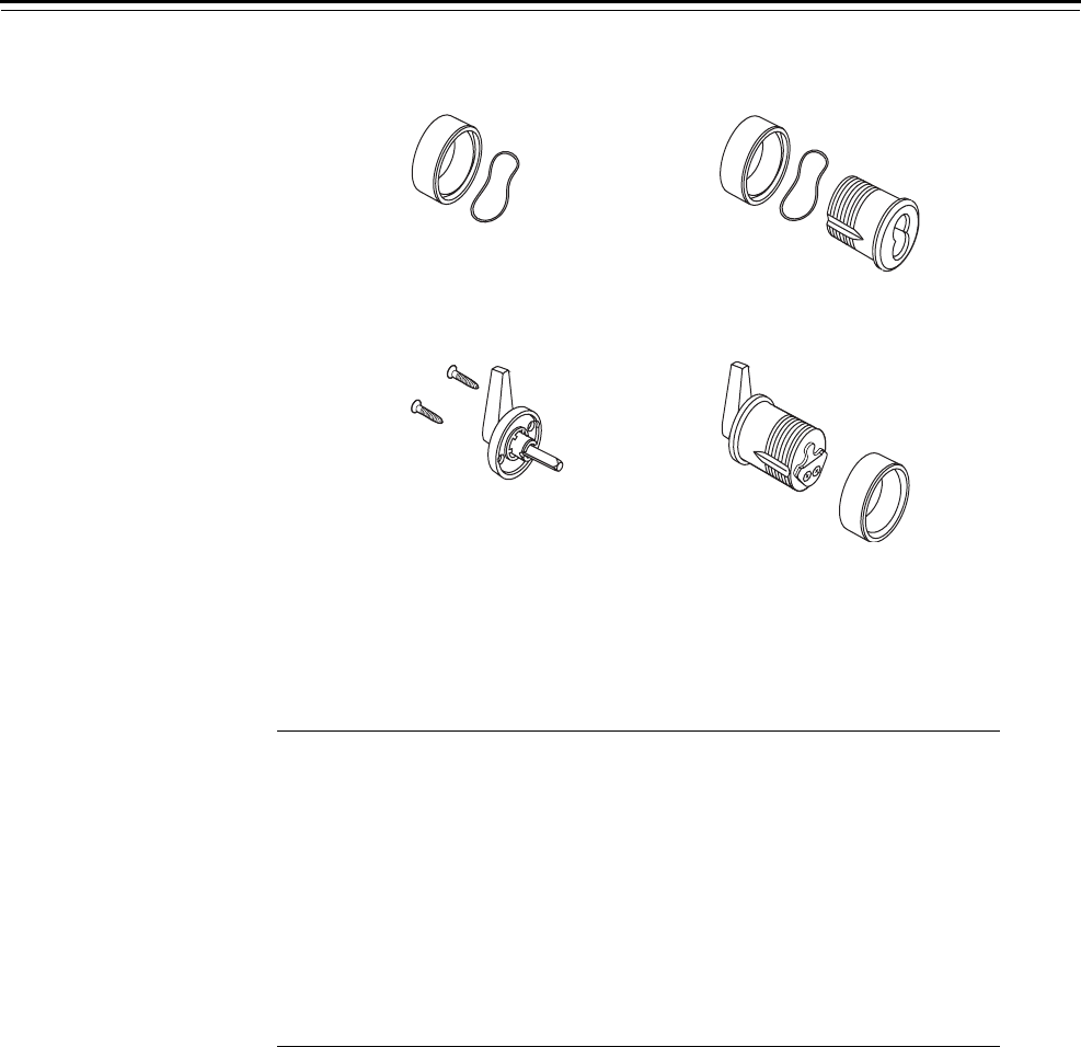
48H & 49H Locks
40H Series Service Manual 7–5
48H TRIM PARTS
Parts list Refer to Figure 7.4 and the table below to find the trim part you need.
Figure 7.4 Deadbolt trim
4
2
3
1
Qty. per function
Item Part No. Description K L M R
1 B35103 Cylinder ring assembly for
single-keyed functionsa
a. Includes wavy washer.
11 1
not shown B35105 Cylinder ring assembly for
double-keyed functions†21
2 See page 5–3 OS4 trim kit 1121
3 See page 5–7 IS5 trim kit 1
4 B35401 Turn knob cylinder
for right hand doors
1
not shown B35405 Turn knob cylinder
for left hand doors
1
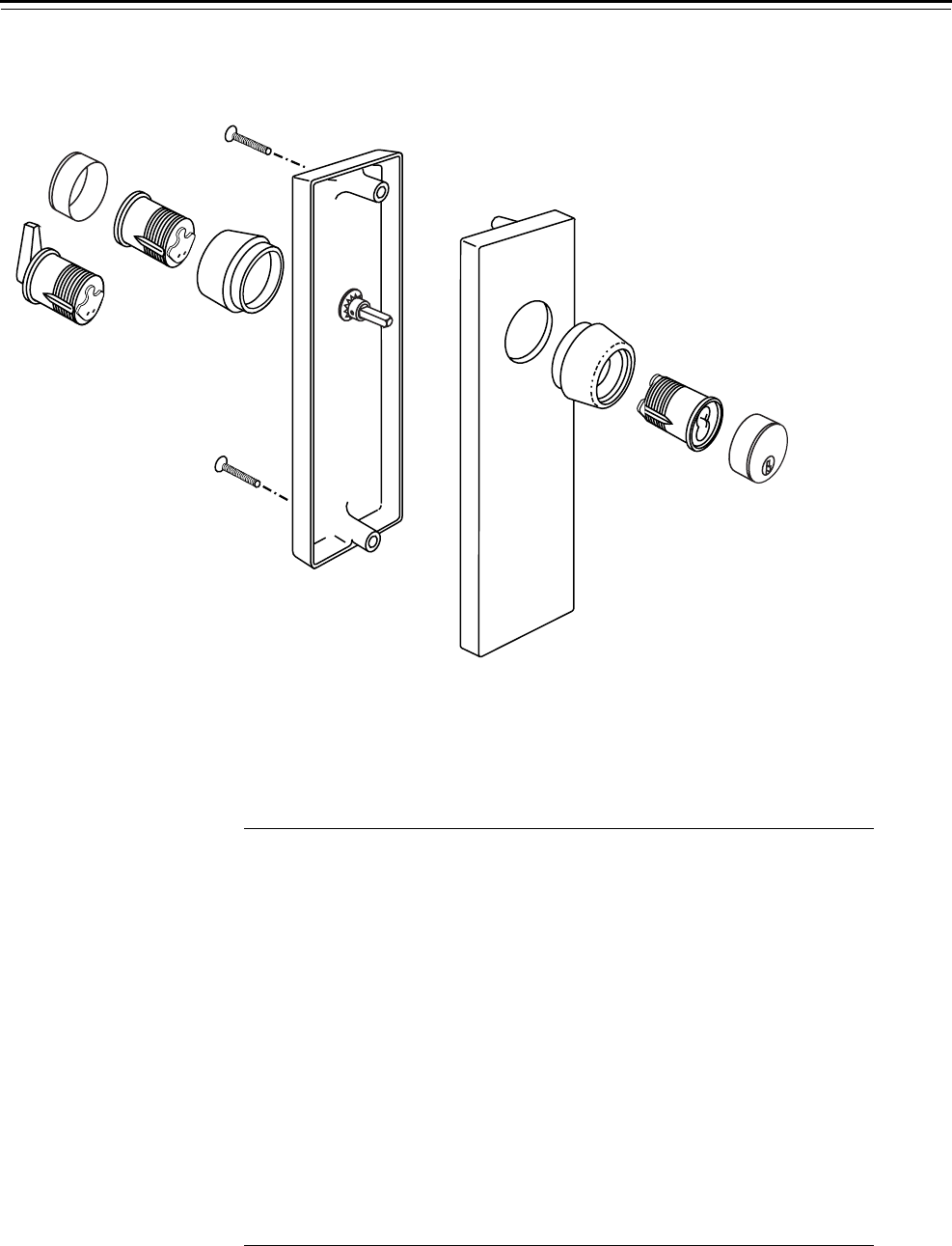
48H & 49H Locks
7–6 40H Series Service Manual
49H HIGH SECURITY DEADBOLT TRIM PARTS
Parts list Refer to Figure 7.5 and the table below to find the trim part you need.
Figure 7.5 High security deadbolt trim
2
3
4
5
1
6
7
5
4
3
1
Qty. per function
Item Part No. Description K L M R
1a
a. Use screw kit #2. For screw kit information, see page 5–19.
M trim escutcheon screw 1111
2 B35519 Turn knob cylinder
for right hand doors
1
not shown B35520 Turn knob cylinder
for left hand doors
1
3 C44470 High security cylinder ring 1121
4 B19436 High security cylinder 1121
5 B19563 Non-UL cylinder face 1121
not shown B19446 UL cylinder face 1121
6 B45213 Inside escutcheon assembly 1
not shown C44463 Inside escutcheon assembly 1
not shown B45220b
b. These escutcheon assemblies include the hardened security plate (A34377).
Inside escutcheon assembly 1
not shown C44461 Inside escutcheon assembly 1
7 B45221bOutside escutcheon 1111
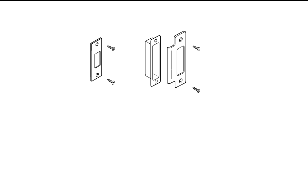
48H & 49H Locks
40H Series Service Manual 7–7
STRIKES AND STRIKE BOXES
Parts list Refer to Figure 7.6 and the table below to determine what strike part
number to use for your 1 3/4″ thick door.
Figure 7.6 Strikes and strike box
1
23
Item Part No. Description
not shown C34361 48HS1 strike box
1 A34360 48HS1 strike (non-beveled)
2 B34380 48HS2 strike box
3 C18731 48HS2 strike (beveled)

48H & 49H Locks
7–8 40H Series Service Manual
TROUBLESHOOTING
This table summarizes the possible causes for certain lock problems.
For problems with the core and key, such as difficulty removing or
inserting the key or difficulty turning the key, see the Core and Key
Service Manual.
You notice… Possible causes include… You should…
Deadbolt will not extend. Lock was ordered as an R function. Check the part nomenclature and
ensure the R function is needed for
the application.
Deadbolt will not retract. Handing has been ordered
incorrectly.
Check to ensure the case and thumb
turn cylinder are the correct
handing for the door. If not, order
the correct case and thumb turn
cylinder.
Key will not operate deadbolt. Incorrect cam has been installed. Install cylinder with proper cam
(pg. 7-5).

40H Series Service Manual A–1
AGLOSSARY
Armored front The mortise lock front and faceplate designed to
prevent tampering with the cylinder retainer screw
and case mounting screws.
Auxiliary dead latch A latch that prevents the latchbolt from being loided
when the door is closed. See loiding.
Backset The distance from the faceplate to the center of the
cylinder or lever/knob.
Bevel See Door bevel.
Cam See Cylinder cam.
Core See Interchangeable core.
Cylinder See Mortise cylinder.
Cylinder cam A rotating part of a keyed cylinder that drives the
deadbolt or latchbolt.
Cylinder die A tool for rethreading a 1 5/32″ diameter cylinder.
Cylinder ring A metal ring that fits around the cylinder and
protects it from tampering. The cylinder ring also
spaces the cylinder out to the right position.
Cylinder tap A tool for rethreading case threads.
Cylinder wrench A tool for installing, removing, and testing cylinders.
Door bevel The angle on the edge of a door.
Dummy cylinder A nonfunctional mortise cylinder used only to plug a
cylinder hole.
Dummy trim Trim only (without lock). Used mainly on the
inactive door of a double door.

Glossary
A–2 40H Series Service Manual
Emergency key The key that retracts the deadbolt of a privacy lock (L or LT function).
Escutcheon A surface-mounted plate that covers holes that were made in the door
for knobs and cylinders.
Faceplate A finished part of a mortise lock that covers the armored front. See
Armored front.
Figure-8 The basic shape of the interchangeable core and its housing (door
knob, cylinder, padlock, and so forth). See also Interchangeable core.
Hand of door The swing direction of the door as viewed from the outside of the door.
A right-handed (RH) door is hinged on the right and swings inward. A
left-handed (LH) door is hinged on the left and swings inward. If either
of these doors swings outward, it is a right-hand reverse bevel (RHRB)
door, or a left-hand reverse bevel (LHRB) door respectively.
High edge of door bevel The edge of the door that is closer to the frame.
Hub toggle Mortise case feature used upon installation to configure the inside and
outside knob/levers as always unlocked or lockable for selected lock
functions.
Interchangeable core A figure-8 shaped device that contains all mechanical parts for a
masterkeyed system. The interchangeable core can be removed by a
special control key and can be recombinated without disassembling the
lock. See also Figure-8.
Life Safety Code® A document, developed by the National Fire Protection Association
(NFPA) that regulates building construction to prevent injury in case of
fire. Code sections 2-4, and 5-2.1.5 apply to locks and latches.
Lock function The way a lock operates. The function determines appropriate
applications for the lock, such as; how the latchbolt is operated, how
the deadbolt is operated, and how the knobs/levers are locked and
unlocked.
Locking toggle Mortise case feature that allows a user to lock or unlock the outside
lever or knob for selected lock functions.
Loiding A burglary attack method that uses a credit card-like object. This object
is inserted between the door and the frame to separate the latchbolt
from the strike.
Mortise cylinder A threaded lock cylinder that screws directly into the lock case. A key-
driven rotating cam, attached to the back, drives the locking
mechanism.
Mortise cylinder cam
assembly tool
A tool for assembling the cylinder cam to the mortise cylinder.
Mortise A rectangular cavity cut into the edge of a door. Can also mean the act
of making such a cavity.
Mortise lock A lock that fits into a mortise. Other locks fit into bored holes or mount
to a surface. See also Mortise.

Glossary
40H Series Service Manual A–3
Removable core See Interchangeable core.
Reverse bevel See Hand of door.
Shifting cam A spring-loaded cam that shifts back to drive another mechanism. See
also Cylinder cam.
Spanner wrench A wrench used to tighten a rose ring onto a door.
Stop screw Mortise case feature that fixes the position of the outside lever for TD,
B, BW, H, and HJ deadbolt function locks.
Swing See Hand of door.
Tactile lever/knob A lever/knob with deep grooves cut into its surface or a lever with an
abrasive strip affixed to the inside of the lever. Tactile levers and knobs
improve grip and can also serve as a warning when entering hazardous
areas.
Template A precise, detailed hole pattern that serves as a guide for the mortising
and drilling of doors and frames.
Visual indicator A dial assembly, used primarily hotel function locks, that shows
whether the deadbolt or latchbolt is locked. Icons on the dial indicate
vacant or occupied status.

Glossary
A–4 40H Series Service Manual

40H Series Service Manual B–1
BINSTALLATION INSTRUCTIONS
The following pages contain:
■Installation Instructions for 45H & 47H Mortise
Locks
■Installation Instructions for 45HW & 47HW
Electrified Mortise Locks
■Installation Instructions for 48H & 49H Mortise
Locks

Installation Instructions
B–2 40H Series Service Manual
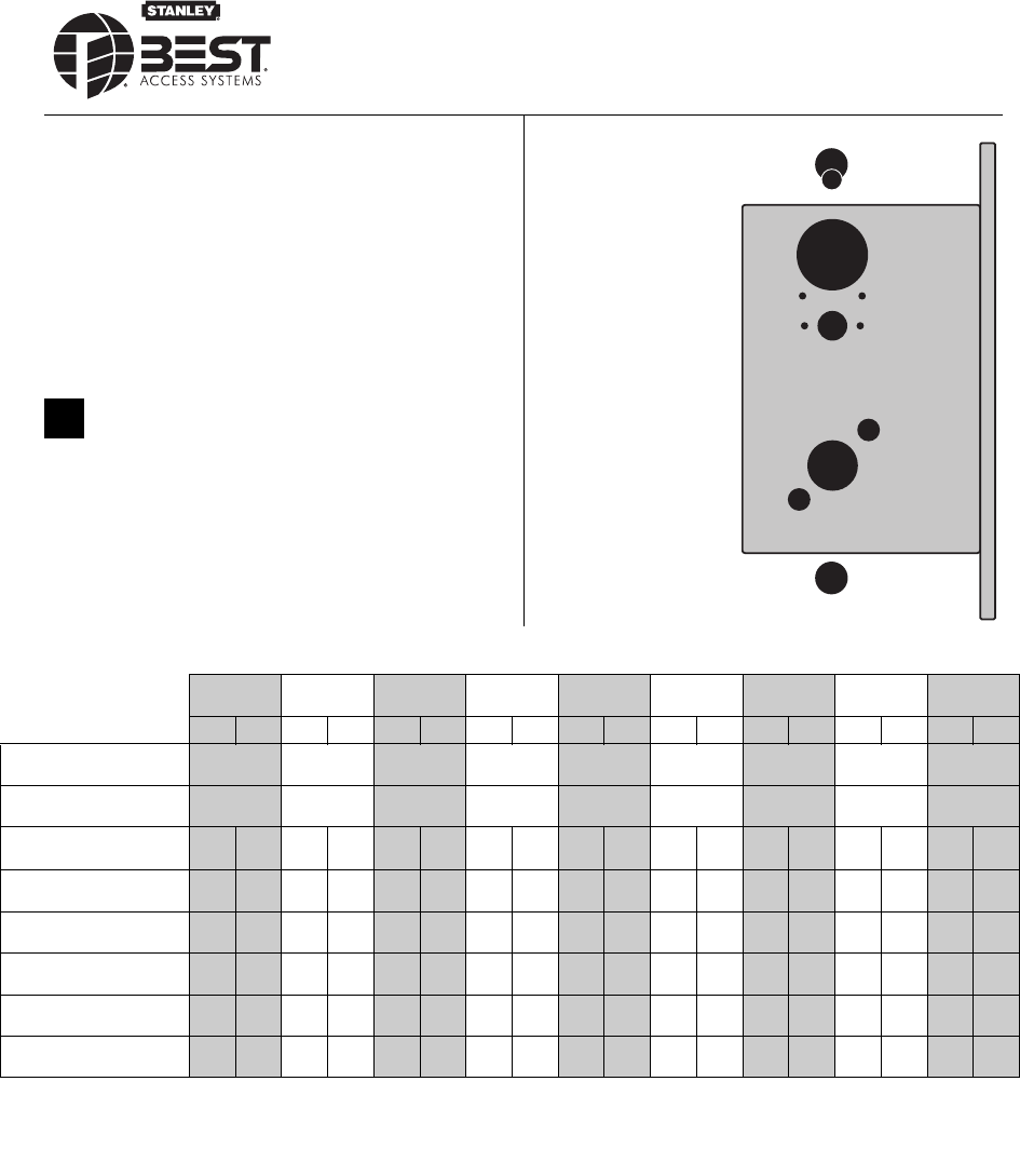
BEST ACCESS SYSTEMS
a Division of Stanley Security Solutions, Inc.
1
Contents
These installation instructions describe how to install your
45H & 47H Mortise Lock. Topics covered include:
Finishing the door preparation ...................................... 1
Configuring and installing the mortise case................. 3
Installing the trim............................................................ 5
Finishing the installation..............................................11
For instructions to install 45HW & 47HW electrified
functions, see the Installation Instructions for 45HW &
47HW Electrified Mortise Locks (T81612).
1Identify holes to drill
1 Determine the lock function to be installed.
2 Determine the inside and outside, hand, and bevel of
the door.
3 See the Holes by Function table and Figure 1 to
determine the holes to be drilled for the lock function.
Figure 1 Identifying holes to drill
A
B
C / D
FE
G
G
H
A
E
For hole sizes, see the
H15 Template (T81163).
JJ
Installation Instructions for
45H & 47H Mortise Locks
Functions
Holes by Function A, D, R,
RHB, B5
AB, AT, B, BA,
BW, HJ, T, TA, TD AD C, CHB, G, IND,
INL, S, W, B7 H L, LB, LT N, NX RD, WD YD
Holes to drill I/S O/S I/S O/S I/S O/S I/S O/S I/S O/S I/S O/S I/S O/S I/S O/S I/S O/S
AM & N forged trim
(2 holes)†
† Determine trim holes based on trim type.
Through
door
Through
door
Through
door
Through
door
Through
door
Through
door
Through
door
Through
door
Through
door
BJ trim†Through
door
Through
door
Through
door
Through
door
Through
door
Through
door
CStandard cylinder or
DHigh security cylinder‡
‡ To qualify for the UL 437 high security listing, use the M escutcheon and the 1E7J4 cylinder. The 1E7K4 cylinder is available for use with
either M trim or sectional trim, but does not qualify for the UL437 high security listing. This option is not available for H and HJ function locks.
■■■■■ ■■■ ■
EH, R & S trim thumb turn
mounting screw (2 holes)†■ ■ ■ ■
FEmergency key /
thumb turn access ■ ■ ■ ■■■
GTrim mounting
(2 holes)†† ■■■■ ■■■■■■■ ■
HLever†† ■■■■ ■■■■■■■ ■
JH & R trim visual indicator
mounting screw (2 holes)†■
†† Because these holes pass through the mortise pocket, it is recommended that each hole be drilled separately rather than straight through.
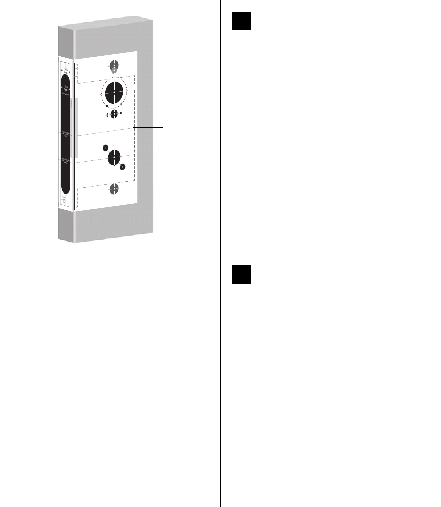
Installation Instructions for 45H & 47H Mortise Locks
BEST ACCESS SYSTEMS
a Division of Stanley Security Solutions, Inc.
Finishing the door preparation
2
2Align templates
Note: If the door is a fabricated hollow metal door,
determine whether it is properly reinforced to support
the lock. If door reinforcement is not adequate, consult
the door manufacturer for information on proper
reinforcement. For dimensions for preparing metal
doors, see the H16 Template—Installation
Specifications for 45H & 47H Mortise Locks (T81166).
1 Separate the 4 templates provided on the H15
Template—Installation Template for 45H & 47H Mortise
Locks and 45HW & 47HW Electrified Mortise Locks
(T81163).
2 Position one of the door edge templates on the door,
making sure that the lock case mortise shown on the
template aligns with the mortise pocket prepared in
the door.
3 Using the centerlines on the door edge template as a
guide, position the appropriate door template on each
side of the door. You need to take the bevel into
account. Tape the templates to the door.
3Center punch and drill holes
1 Center punch the necessary drill points. See the
instructions on the template.
2 Drill the holes.
Note 1: To locate the center of a hole on the opposite
side of the door, drill a pilot hole completely through the
door.
Note 2: For holes through the door, it is best to drill
halfway from each side of the door to prevent the door
from splintering.
Note 3: For trim outside only functions (such as ZD and
ZR) and trim inside only functions (such as XD and XR),
prepare surface mount trim holes on the trim side of the
door as needed. Do not prepare trim holes on the
opposite side of the door. For 1DT and 2DT hole
preparation, see H15 Template—Installation Template
for 45H & 47H Mortise Locks and 45HW & 47HW
Electrified Mortise Locks (T81163).
Vertical centerline
of lever
H
G
A
Horizontal centerline
of lock
G
3/8 in
10 mm
7/8 in
23 mm
3/8 in
10 mm
5/8 in
16 mm
A
B
DC
1 3/4 in
45 mm
1 1/4 in
32 mm
EF
1/8 in
3 mm
1/2 in
13 mm
E
Horizontal centerline
of lever
Align to edge of door.
Low edge (narrow side)
High edge (wide side)
Note
:
Use this template for the
inside of
a LH or LHRB door
or the
outside
(keyed side) of a RH or RHRB door
.
For metal doors, see the
H16
Template
—
Installation Specifications for 45H & 47H
Mortise
Locks
(T81166).
Strike lip
Hole Descriptions
A
M & N forged
trim (2)
B
J trim (1)
C
Cylinder (1)
D
High security
cylinder (1)
E
H, R, & S trim
thumb turn
mounting screw (2)
F
Emergency key /
thumb turn
access (1)
G
Trim mounting (2)
H
Lever (1)
J
H & R trim
visual indicator
mounting screw (2)
JJ
1/8 in
3 mm
Figure 2 Aligning the templates
Installation
template
Door edge
template
Centerline
Centerline
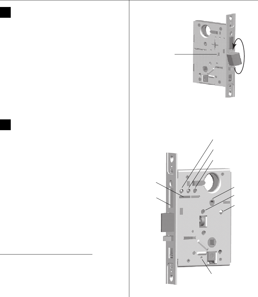
Installation Instructions for 45H & 47H Mortise Locks
BEST ACCESS SYSTEMS
a Division of Stanley Security Solutions, Inc.
3
Installation Instructions for 45H & 47H Mortise Locks
Configuring & installing the mortise case
4Rotate latchbolt (if necessary)
Note: If a function specific mortise case was ordered,
some steps for configuring the case have already been
performed at the factory.
1 Determine whether you need to rotate the latchbolt to
match the handing of the door.
Note: The angled surface of the latchbolt must contact
the strike when the door closes.
2 If you need to rotate the latchbolt, insert a flat blade
screwdriver into the latch access point approximately
1/2″ into the case and press to extend the latch out of
the case. See Figure 4.
3 Rotate the latchbolt 180 degrees and allow it to retract
into the case.
5Set shuttle screws (UNR case only)
Note 1: The UNR (universal latch) mortise case is
shipped with the shuttle screws in position 0 and
position 5.
Note 2: To position the shuttle, insert a screwdriver into
the opening for the thumb turn hub and rotate the
shuttle.
■For an N function, position the shuttle towards the
face of the case and move the shuttle screw from
position 0 to position 1.
■For a D, NX, or W function, position the shuttle
towards the back edge of the case and move the
shuttle screw from position 0 to position 3.
■For an A function, position the shuttle in the middle
of the case and move the shuttle screw from
position 0 to position 4. Then move the shuttle
screw from position 5 to position 2.
Shuttle screw positions
Function Shuttle screw positions
A2 & 4
AT, C, INL, R, RHB 0 & 5
D, NX, W 3 & 5
N1 & 5
Figure 4 Rotating the latchbolt
Latch access point
Figure 5 Setting the shuttle screws and stop screw
Position 0
(storage)
Position 1
Position 2
Position 3
Position 4
Position 5
Stop screw
(for deadbolt functions
with fixed outside lever)
Thumb
turn hub
Shuttle
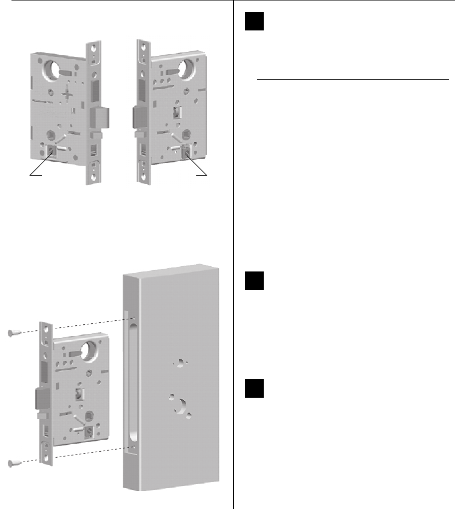
Installation Instructions for 45H & 47H Mortise Locks
BEST ACCESS SYSTEMS
a Division of Stanley Security Solutions, Inc.
Configuring & installing the mortise case
4
6Position hub toggles (if necessary)
1 Check whether the hub toggles are in the proper
position for the lock. See the table below and Figure 6.
Note: For LH & LHRB doors, the inside is the back side of
the case and the outside is the cover side of the case.
For RH & RHRB doors, the inside is the cover side of the
case and the outside is the back side of the case.
2 To change the position of a hub toggle, remove the
toggle screw, move the toggle into the desired
position, and re-tighten the screw.
7Install stop screw (deadbolt functions
with fixed outside lever only)
Note: The TD, BW, H, and HJ deadbolt functions, which
have a fixed outside lever, require the stop screw.
If converting a UNAB (universal deadbolt) mortise case to
one of the above functions, install the self-tapping stop
screw. See Figure 5 on page 3.
8Install mortise case
1 Drill the holes for the case mounting screws.
2 Insert the mortise case into the mortise cavity.
Note: The armored front of the mortise case self-adjusts
to the door bevel.
3 Secure the mortise case with the case mounting
screws.
Hub toggle positions
Function Hub toggle positions
A, AB, AT, C, CHB, D, H,
HJ, IND, INL, L, LT, NX, R,
RHB, T, TA, TD, X, XR, ZD
Inside down (always unlocked) &
outside up (lockable)
B, BA, BW, B5, B7, G, LB,
S, W
Both up
NBoth down
Figure 6 Positioning hub toggles
Hub toggleHub toggle
Figure 8 Installing the mortise case
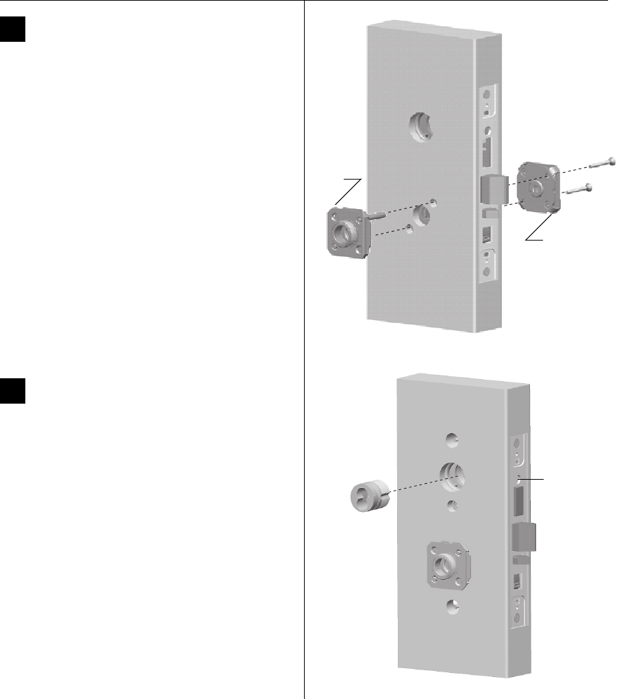
Installation Instructions for 45H & 47H Mortise Locks
BEST ACCESS SYSTEMS
a Division of Stanley Security Solutions, Inc.
5
Installation Instructions for 45H & 47H Mortise Locks
Installing the trim
9Install trim mounting plates
1 For J trim, position the J alignment plate (Figure 11b)
on the outside of the door.
Note: For J trim on one side only, do not install the
alignment plate.
2 For all trim, insert the outside trim mounting plate
through the door and mortise case.
Note: For trim on one side only, surface mount the inside
mounting plate to the trim side of the door using two
#8 × 1″ PFH surface mounting screws. Do not install the
outside mounting plate.
3 Position the inside trim mounting plate opposite the
outside trim mounting plate and screw them securely
in place.
Caution: Do not overtighten the trim mounting
plate screws. Overtightening may damage the
locking mechanism.
10 Install concealed cylinder (N trim only)
1 Use a cylinder wrench (ED211) to thread the cylinder
into the mortise case so that the groove around the
cylinder is even with the door surface.
Caution: A malfunction can occur if the cylinder is
threaded in too far.
2 Secure the cylinder in the mortise case with the
cylinder retainer screw.
Figure 9 Installing the trim mounting plates
Outside
mounting
plate
Inside
mounting
plate
Figure 10 Installing the concealed cylinder
Cylinder
retainer
screw
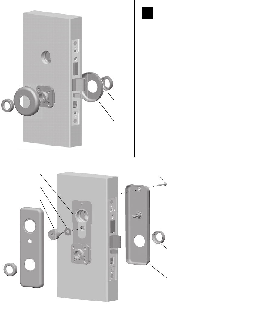
Installation Instructions for 45H & 47H Mortise Locks
BEST ACCESS SYSTEMS
a Division of Stanley Security Solutions, Inc.
Installing the trim
6
11 Install roses or escutcheons
For sectional trim (Figure 11a)
1 Position the inside rose on the door so it is centered on
the trim mounting plate.
2 Use the spanner wrench (KD316) to install the rose
ring onto the inside mounting plate.
3 Position the outside rose on the door so it is centered
on the trim mounting plate.
4 Use the spanner wrench to install the rose ring onto
the outside mounting plate.
Note: For instructions for installing the visual indicator
with sectional trim, see Task 13 on page 8.
For J trim (Figure 11b)
1 For H function locks, position the plastic spacer on the
spindle of the visual indicator dial. With the deadbolt
retracted, position the visual indicator (VIN) dial in the
door with the text oriented at the top.
2 Position the inside escutcheon on the door so it is
centered on the trim mounting plate. Install the
escutcheon screw.
3 Use the spanner wrench
(KD316) to install the trim ring
onto the inside mounting
plate.
4 Position the outside
escutcheon on the door over
the alignment plate.
5 Use the spanner wrench to
install the trim ring onto the
outside trim mounting plate.
Figure 11a Installing the roses
Rose
Rose
ring
Figure 11b Installing the J trim escutcheons
Trim ring
Inside
escutcheon
Escutcheon screw
VIN dial
Alignment plate
Plastic spacer
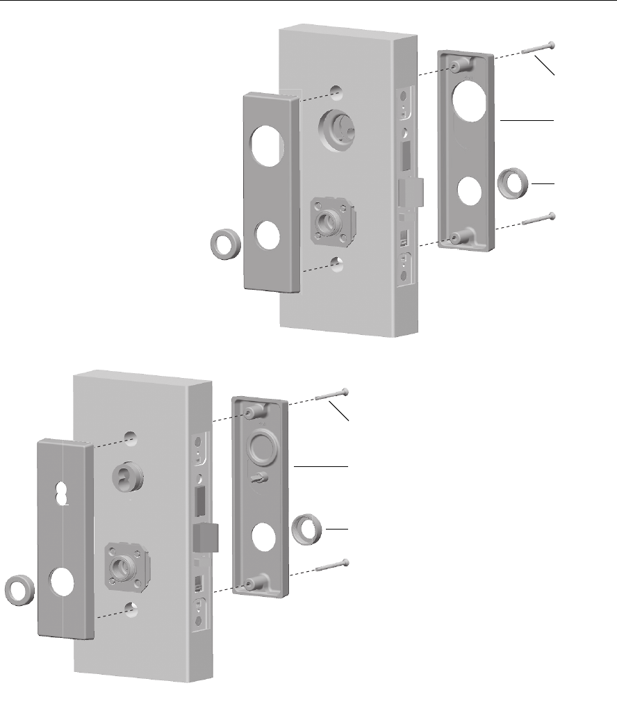
Installation Instructions for 45H & 47H Mortise Locks
BEST ACCESS SYSTEMS
a Division of Stanley Security Solutions, Inc.
7
Installation Instructions for 45H & 47H Mortise Locks
Installing the trim
For M trim (Figure 11c) or
N trim (Figure 11d)
1 Position the inside and outside
escutcheons on the door so they
are centered on the trim mounting
plates.
2 Install the upper and lower
escutcheon screws from the inside
of the door.
3 Use the spanner wrench (KD316)
to install the trim rings onto the
inside and outside trim mounting
plates.
Figure 11c Installing the M trim escutcheon
s
(47H M trim shown)
Escutcheon
screw
Inside
escutcheon
Trim ring
Figure 11d Installing the N trim escutcheons
Escutcheon
screw
Inside
escutcheon
Trim ring
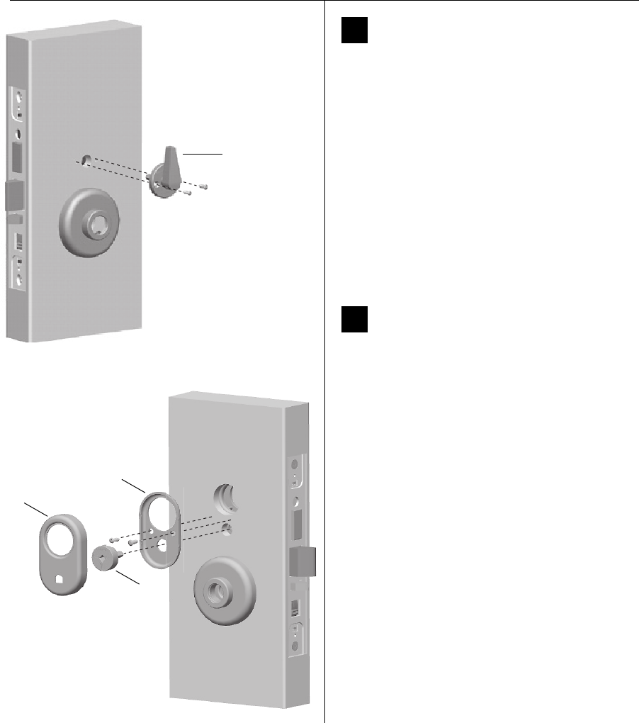
Installation Instructions for 45H & 47H Mortise Locks
BEST ACCESS SYSTEMS
a Division of Stanley Security Solutions, Inc.
Installing the trim
8
12 Install thumb turn or emergency
access plate (if necessary)
Note 1: To determine which functions require a thumb
turn on the inside of the door, refer to the Holes by
Function table on page 1.
Note 2: The UNR (universal latch) mortise case is
shipped with a thumb turn. Install it only for an A or AT
function lock.
Note 3: Install the emergency access plate on the
outside of the door for privacy function (L, LB, LT) locks.
1 Orient the thumb turn so it points up when the
deadbolt is retracted and towards the hinge edge of
the door when the deadbolt is extended.
2 Install the thumb turn or emergency access plate using
the two screws provided. See Figure 12.
13 Install visual indicator trim
(H or R sectional trim)
Note: Install the visual indicator trim on the outside of
the door for H function locks. The visual indicator also
can be installed with other functions (such as IND, INL, L,
LB, LT, TD) as needed. The visual indicator is available for
H, R, and J trim.
1 Aligning the cylinder opening in the visual indicator
mounting bracket with the cylinder opening in the
door, install the mounting bracket using the two
screws provided.
2 Make sure that the deadbolt is retracted (the thumb
turn is pointing up).
3 Orient the visual indicator (VIN) dial with the text at
the top and position it in the door as shown in
Figure 13.
4 Aligning the cylinder opening in the visual indicator
cover with the cylinder hole in the door, press the
cover onto the mounting bracket.
5 Rotate the thumb turn and check that the visual
indicator operates properly.
Note: The unlocked icon should show when the
deadbolt is retracted. The locked icon should show when
the deadbolt is extended.
Figure 12 Installing the thumb turn or
emergency access plate (not shown
)
Thumb turn
Figure 13 Installing the visual indicator trim
Cover
Mounting
bracket
VIN
dial
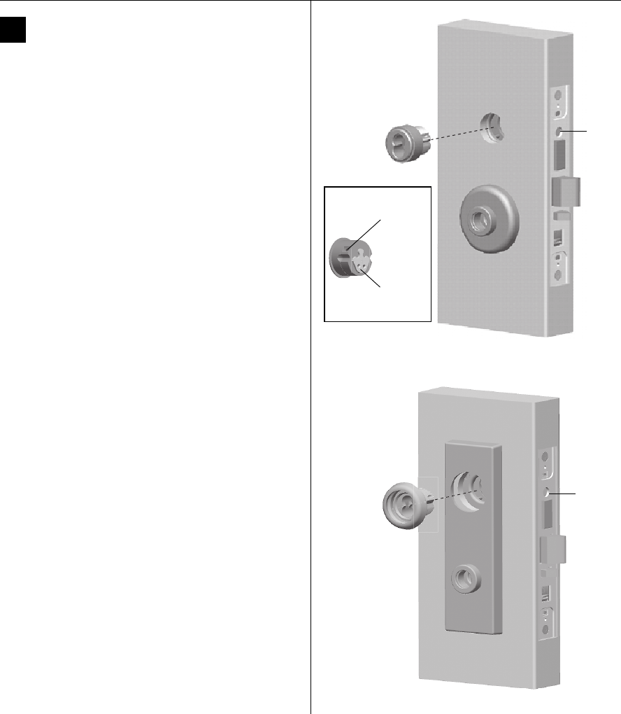
Installation Instructions for 45H & 47H Mortise Locks
BEST ACCESS SYSTEMS
a Division of Stanley Security Solutions, Inc.
9
Installation Instructions for 45H & 47H Mortise Locks
Installing the trim
14 Install standard or high security
cylinder (if necessary)
1 Using a narrow-blade screwdriver, insert the blade
into the cylinder’s figure-8 opening and back the set
screw into the cylinder until the tip of the set screw is
below the threads of the cylinder.
2 Make sure the washer (standard cylinder only) and
cylinder ring are positioned on the cylinder.
3 Rotate the cylinder cam to the 12 o’clock position.
4 Use a cylinder wrench (ED211) to thread the cylinder
into the mortise case.
For a standard cylinder, rotate the cylinder until the
cylinder ring is flush against the door.
For a high-security cylinder, rotate the cylinder until the
cylinder head touches the inside rim of the cylinder
ring.
Caution: A malfunction can occur if the cylinder is
threaded in too far.
5 Using a narrow-blade screwdriver, insert the blade
into the figure-8 opening and tighten the small set
screw (installed in the cylinder) into the lock case.
6 Secure the cylinder in the mortise case with the
cylinder retainer screw.
Figure 14a Installing the standard cylinder
Cylinder
retainer
screw
Set
screw
location
Cam in
12 o’clock
position
Back view of cylinder
Figure 14b Installing the high-security cylinder
Cylinder
retainer
screw
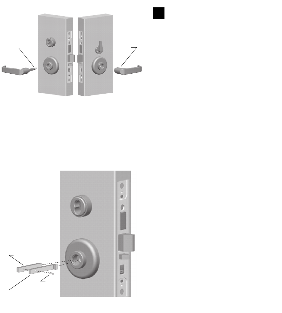
Installation Instructions for 45H & 47H Mortise Locks
BEST ACCESS SYSTEMS
a Division of Stanley Security Solutions, Inc.
Installing the trim
10
15 Install inside and outside levers
For standard lever installation (Figure 15a)
1 Unscrew the inside spindle one full turn to allow the
spindles to turn freely.
Note: Remove the label from the inside spindle.
2 With the handle pointing toward the door hinges,
insert the outside lever and spindle assembly into the
lock from the outside of the door.
Note: The 17 style lever is handed. The lever should
curve downward when installed on the door.
3 Slide the inside lever onto the inside spindle and
secure it with the set screw.
4 Turn the levers to check that they operate smoothly.
For one side only lever installation (Figure 15b)
For one side only lever installation, use a hook spindle.
Note: The hook spindle can be installed on either side of
the door, but the inside lever should always be used with
the hook spindle.
1 Insert the upper hook spindle into the hub cavity with
the hook towards the latch as shown in Figure 15b.
2 Insert the lower hook spindle alongside the upper
spindle and align the pin holes.
3 Push the pin into the spindles. Make sure the pin is
fully inserted.
4 Slide the lever onto the spindle and secure with the set
screw.
5 Turn the lever to check that it operates smoothly.
Figure 15a Installing the levers
Location
of set
screw
Outside of door Inside of door
Spindle
assembly
Figure 15b Installing the hook spindle
1 Upper hook spindle
2 Lower hook spindle
3 Pin
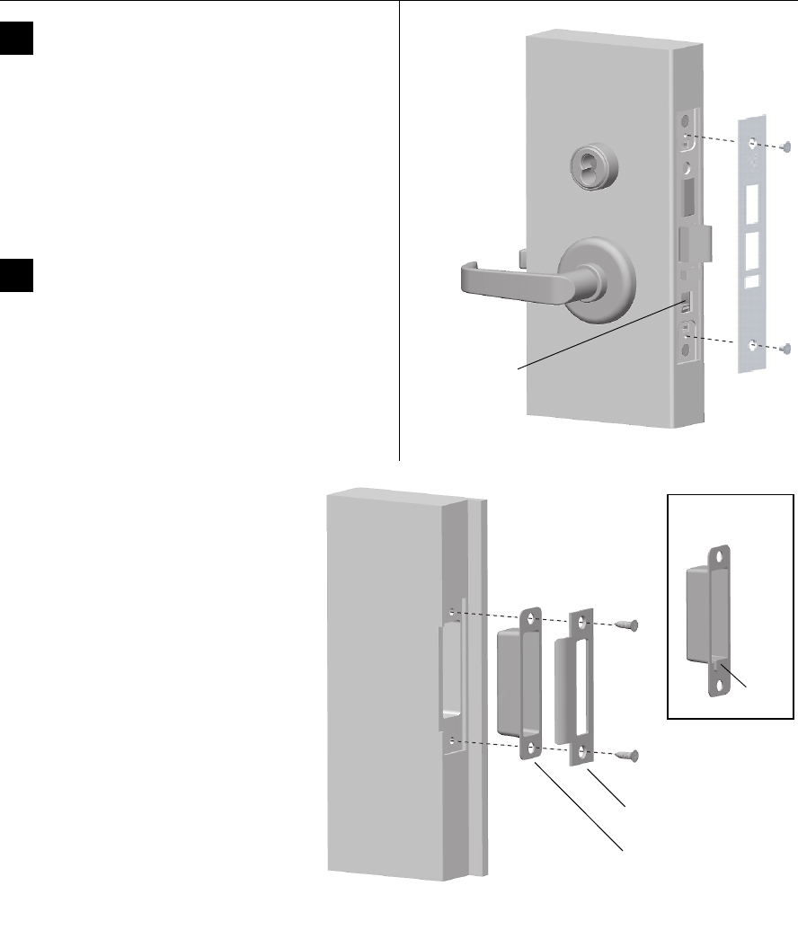
Installation Instructions for 45H & 47H Mortise Locks
BEST ACCESS SYSTEMS
a Division of Stanley Security Solutions, Inc.
11
Installation Instructions for 45H & 47H Mortise Locks
Finishing the installation
16 Install mortise case faceplate
Note: Most locks ship with only one faceplate. The UNAB
and UNR locks ship with two faceplates each, allowing
for multiple function configurations. For AB (UNAB) and
A (UNR) function locks, use the faceplate that exposes the
locking toggle.
1 Secure the mortise case faceplate to the mortise case
with the faceplate mounting screws.
2 Check the lock for proper operation.
17 Install strike box and strike plate
1 If the door jamb has not been mortised for the strike box
and strike plate, perform these steps:
a On the door jamb, locate the horizontal centerline
of the strike (3/8″ above the centerline of the lock),
as well as the vertical centerline of the strike.
b Mortise the door jamb to fit the strike box and
strike plate.
c Drill the holes for the screws used to install the
strike box and strike plate.
2 If the strike box has a filled area, orient the
strike box so that the filled area is down.
3 Insert the strike box into the mortise in the
door jamb. Place the strike plate over the
strike box and secure the strike with the
screws provided.
4 Check the position of the auxiliary bolt
against the strike plate (or the filled area of
the strike box).
Note: The recommended gap between the
door and jamb is 1/8″.
Figure 16 Installing the mortise case faceplate
Locking toggle
Figure 17 Installing the strike box and strike plate
Strike
box
Strike
plate
Filled
area
Strike box with
filled area
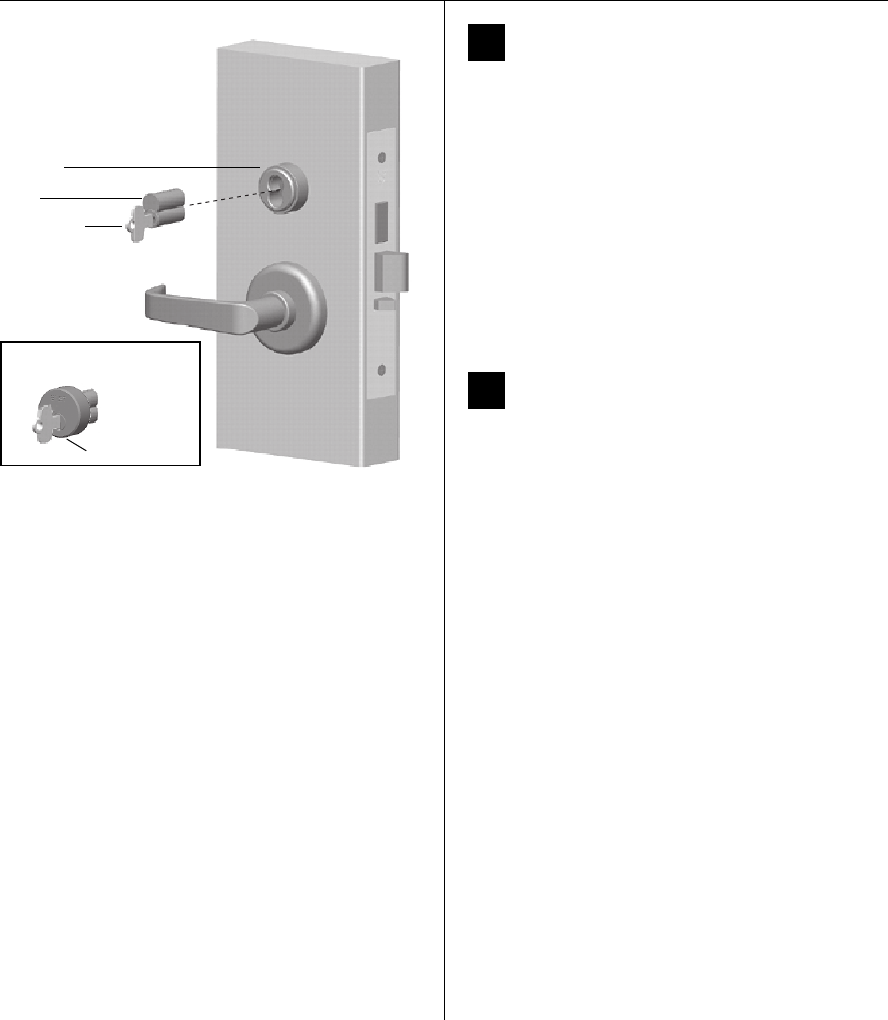
Installation Instructions for 45H & 47H Mortise Locks
BEST ACCESS SYSTEMS
a Division of Stanley Security Solutions, Inc.
Finishing the installation
12
18 Install cores
1 For a high-security cylinder, slide the armored face
down over the core.
2 Insert the control key into the core and rotate the key
15 degrees to the right.
3 With the control key in the core, insert the core and
armored face (high-security cylinder only) into the
cylinder.
4 Rotate the control key 15 degrees to the left and
withdraw the key.
Caution: The control key can be used to remove
cores and to access doors. Provide adequate
security for the control key.
19 Check operation
Check the operation of the lock. For example, check that:
■door latches and opens properly
■deadbolt operates properly
■visual indicator operates properly
■key access works
■door gap is 1/8”
■auxiliary bolt is held inside the case when the door
is closed.
For assistance, contact your local BEST representative.
Figure 18 Installing the core(s)
Control key
Core
Cylinder
Armored face
View of high-security cylinder
© 2005–2006 Stanley Security Solutions, Inc. and Stanley Logistics, Inc.
T81162/Rev C 1907197 ER-7991-12 Nov 2006
Using the latch holdback feature
The latch holdback feature lets you temporarily operate a
door with a CHB or RHB function mortise lock as a free-
swinging door. When latch holdback is engaged, the latch
stays retracted, and both the inside and outside levers
become fixed pull handles.
To engage latch holdback:
1 With the lock unlocked and the door open, turn the
inside lever to the up position.
2 While holding the inside lever in the up position, turn
the key as if to lock the door.
3 Release the inside lever and remove the key at the
12 o’clock position. The latch and inside lever become
fixed.
To disengage latch holdback:
1 Turn the key as if to unlock the door.
2 Remove the key at the 12 o’clock position. The latch
and inside lever release, and the lock operates
normally.
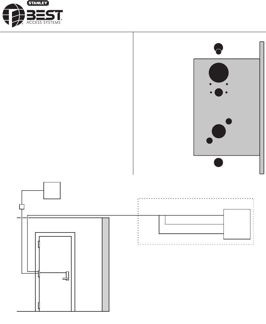
BEST ACCESS SYSTEMS
a Division of Stanley Security Solutions, Inc.
1
Contents
These installation instructions describe how to install your
45HW & 47HW Electrified Mortise Lock. Topics covered
include:
Finishing the door preparation ...................................... 2
Configuring and installing the mortise case................. 6
Installing the trim............................................................ 8
Finishing the installation..............................................13
Figure 1 Identifying holes to drill
A
B
C / D
F
E
G
G
H
A
E
For hole sizes, see the
H15 Template (T81163).
JJ
Installation Instructions for
45HW & 47HW Electrified Mortise Locks
Power
supply
Lock
Wire
transfer
hinge
Power (2)
Temperature
control module
RQE status (2)
Door status (2)
Access
control
panel
Sensor wires Latchbolt or deadbolt status (2)
Wiring diagram for 45HW & 47HW Electrified Mortise Locks
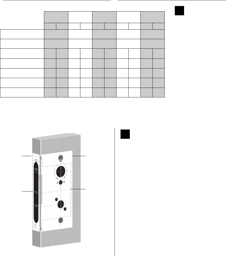
Installation Instructions for 45HW & 47HW Electrified Mortise Locks
BEST ACCESS SYSTEMS
a Division of Stanley Security Solutions, Inc.
Finishing the door preparation
2
2Align templates
Note: If the door is a fabricated hollow metal door,
determine whether it is properly reinforced to support
the lock. If door reinforcement is not adequate, consult
the door manufacturer for information on proper
reinforcement. For dimensions for preparing metal
doors, see the H19 Template—Installation
Specifications for 45HW & 47HW Electrified Mortise
Locks (T81611).
1 Separate the 4 templates provided on the H15
Template—Installation Template for 45H & 47H Mortise
Locks and 45HW & 47HW Electrified Mortise Locks
(T81163).
2 Position one of the door edge templates on the door,
making sure that the lock case mortise shown on the
template aligns with the mortise pocket prepared in
the door.
3 Using the centerlines on the door edge template as a
guide, position the appropriate door template on each
side of the door. You need to take the bevel into
account. Tape the templates to the door.
Vertical centerline
of lever
H
G
A
Horizontal centerline
of lock
G
3/8 in
10 mm
7/8 in
23 mm
3/8 in
10 mm
5/8 in
16 mm
A
B
DC
1 3/4 in
45 mm
1 1/4 in
32 mm
EF
1/8 in
3 mm
1/2 in
13 mm
E
Horizontal centerline
of lever
Align to edge of door.
Low edge (narrow side)
High edge (wide side)
Note
:
Use this template for the
inside of
a LH or LHRB door
or the
outside
(keyed side) of a RH or RHRB door
.
For metal doors, see the
H16
Template
—
Installation Specifications for 45H & 47H
Mortise
Locks
(T81166).
Strike lip
Hole Descriptions
A
M & N forged
trim (2)
B
J trim (1)
C
Cylinder (1)
D
High security
cylinder (1)
E
H, R, & S trim
thumb turn
mounting screw (2)
F
Emergency key /
thumb turn
access (1)
G
Trim mounting (2)
H
Lever (1)
J
H & R trim
visual indicator
mounting screw (2)
JJ
1/8 in
3 mm
Figure 2 Aligning the templates
Installation
template
Door edge
template
Centerline
Centerline
Functions
Holes by Function DEL, DEU TDEL, TDEU TWEL, TWEU,
WEL, WEU LEL, LEU NXEL, NXEU
Holes to drill I/S O/S I/S O/S I/S O/S I/S O/S I/S O/S
AM & N forged trim
(2 holes)†
† Determine trim holes based on trim type.
Through
door
Through
door
Through
door
Through
door
Through
door
BJ trim†Through
door
Through
door
Through
door
Through
door
Through
door
CStandard cylinder or
DHigh security cylinder‡
‡ To qualify for the UL 437 high security listing, use the M escutcheon and the 1E7J4 cylinder. The 1E7K4 cylinder
is available for use with either M trim or sectional trim, but does not qualify for the UL437 high security listing.
■■■ ■
EH, R & S trim thumb turn
mounting screw (2 holes)†■ ■
FEmergency key /
thumb turn access ■■■
GTrim mounting
(2 holes)††
†† Because these holes pass through the mortise pocket, it is recommended that each hole be drilled separately
rather than straight through.
■■■■■■■■■ ■
HLever†† ■■■■■■■■■ ■
1Identify holes
to drill
1 Determine the lock
function to be installed.
2 Determine the inside
and outside, hand, and
bevel of the door.
3 See the Holes by
Function table and
Figure 1 on page 1 to
determine the holes to
be drilled for the lock
function.
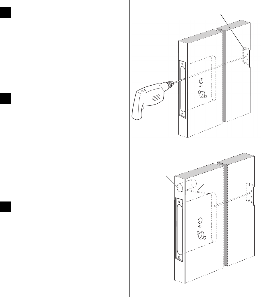
Installation Instructions for 45HW & 47HW Electrified Mortise Locks
BEST ACCESS SYSTEMS
a Division of Stanley Security Solutions, Inc.
3
Installation Instructions for 45HW & 47HW Electrified Mortise Locks
Finishing the door preparation
3Center punch and drill holes
1 Center punch the necessary drill points. See the
instructions on the template.
2 Drill the holes.
Note 1: To locate the center of a hole on the opposite
side of the door, drill a pilot hole completely through the
door.
Note 2: For holes through the door, it is best to drill
halfway from each side of the door to prevent the door
from splintering.
4Drill wire channel through door
Caution 1: Check with your local fire marshal
before drilling a fire-rated door. Drilling through
a fire-rated door may void the fire label.
Caution 2: Be careful to drill straight through the
door, making sure the drill does not break
through the face of the door.
1 Remove the hinge nearest the mortise cavity.
2 Using a 3 to 4 foot drill bit, drill a 3/8″ diameter
channel through the upper back of the mortise cavity
to the center of the nearest hinge mortise.
Note: It may be easier to drill halfway from each side of
the door.
5Prepare door for door status switch
(optional for deadbolt function locks)
1 Locate the centerpoint for the door status switch 2.5″
above the top of the faceplate mortise on the edge of
the door (as shown in Figure 5).
2 Drill a 1″ diameter hole 1 3/4″ deep for the door
status switch.
3 Position the drill so the tip of the bit is approximately
1″ into the hole and the bit is close to the top edge of
the hole. Then drill a 3/8″ channel at approximately a
35° angle from the door status switch hole into the
mortise cavity (as shown in Figure 5).
Figure 4 Drilling the wire channel through the door
Hinge mortise
Figure 5 Preparing for the door status switch
Door status
switch hole 3/8″
channel
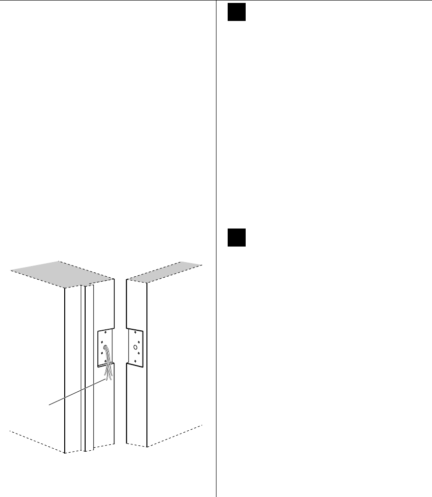
Installation Instructions for 45HW & 47HW Electrified Mortise Locks
BEST ACCESS SYSTEMS
a Division of Stanley Security Solutions, Inc.
Finishing the door preparation
4
6Determine wire gauge for power
wiring
1 Calculate the total length of the power wire run
by summing:
■The distance from the power supply to the first
door.
■If powering more than one door daisy-chained to
the same power supply, add the total distance of
the power runs between the doors.
2 For both 12 volt and 24 volt locks, refer to the table
below to determine the minimum wire gauge based
on the number of doors sharing the power supply and
the total length of the wire run.
7Prepare door for wire transfer hinge
and run field wiring
1 Drill a wire access hole through the frame side of the
hinge mortise where you removed the hinge in Task 4,
Step 1 on page 3.
2 Drill holes (or pockets) for splice connectors in the
frame and door. Refer to the hinge manufacturer’s
specifications for the hole location.
3 De-burr the holes to prevent damage to the hinge
leads.
4 Run the power field wiring from the location for the
lock’s power supply to the location for the wire
transfer hinge.
Note 1: To match the lock’s wire color, use yellow for
12 volts DC power and blue for 24 volts DC power.
Note 2: To minimize lever temperature, install an
8WTCM (temperature control module) in series with the
power and ground wiring within 20 feet of the lock. Use
only one 8WTCM per lock. This module is supplied with
electrically locked (EL) functions and is optional with
electrically unlocked (EU) functions.
(Continued)
1 door 2 doors 3 doors 4 doors Min. wire gauge
250 ft. 125 ft. 75 ft. 60 ft. 18 AWG
400 ft. 200 ft. 130 ft. 100 ft. 16 AWG
600 ft. 300 ft. 185 ft. 150 ft. 14 AWG
Figure 7 Running field wiring
Door frame Door
Field wiring
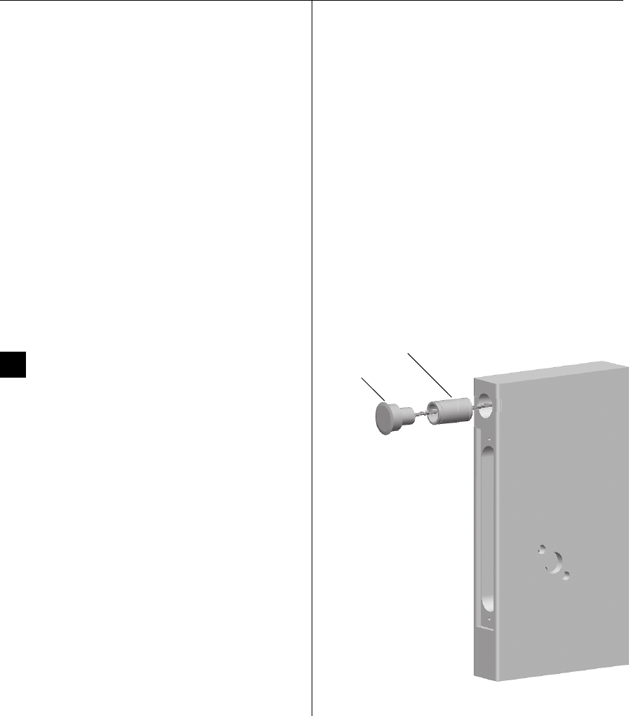
Installation Instructions for 45HW & 47HW Electrified Mortise Locks
BEST ACCESS SYSTEMS
a Division of Stanley Security Solutions, Inc.
5
Installation Instructions for 45HW & 47HW Electrified Mortise Locks
Finishing the door preparation
5 If the lock has an optional door status sensor, latchbolt
status sensor, deadbolt status sensor, and/or RQE
status sensor, run the sensor wiring from the location
of the access control panel to the location for the wire
transfer hinge.
To match the sensor wire colors, refer to the table
below.
7 Pull the field wiring down the wall and through the
access hole in the frame.
8Install door status switch
(optional for deadbolt function locks)
1 Position the shield on the door status switch with the
notch facing downwards (towards the mortise
pocket).
Caution: Make sure the wires are not routed
across any sharp edges or over any surface that
could damage its sleeving.
2 Feed the wires for the door status switch into the door
status switch hole and through the channel into the
mortise cavity.
3 Insert the door status switch assembly into the door
status switch hole.
Wire connection Color No. of wires
Deadbolt status sensor Blue 2
Door status sensor White 2
Latchbolt status sensor Violet 2
RQE status sensor Brown & Orange 2
Figure 8 Installing the door status switch
Door
status
switch
Shield
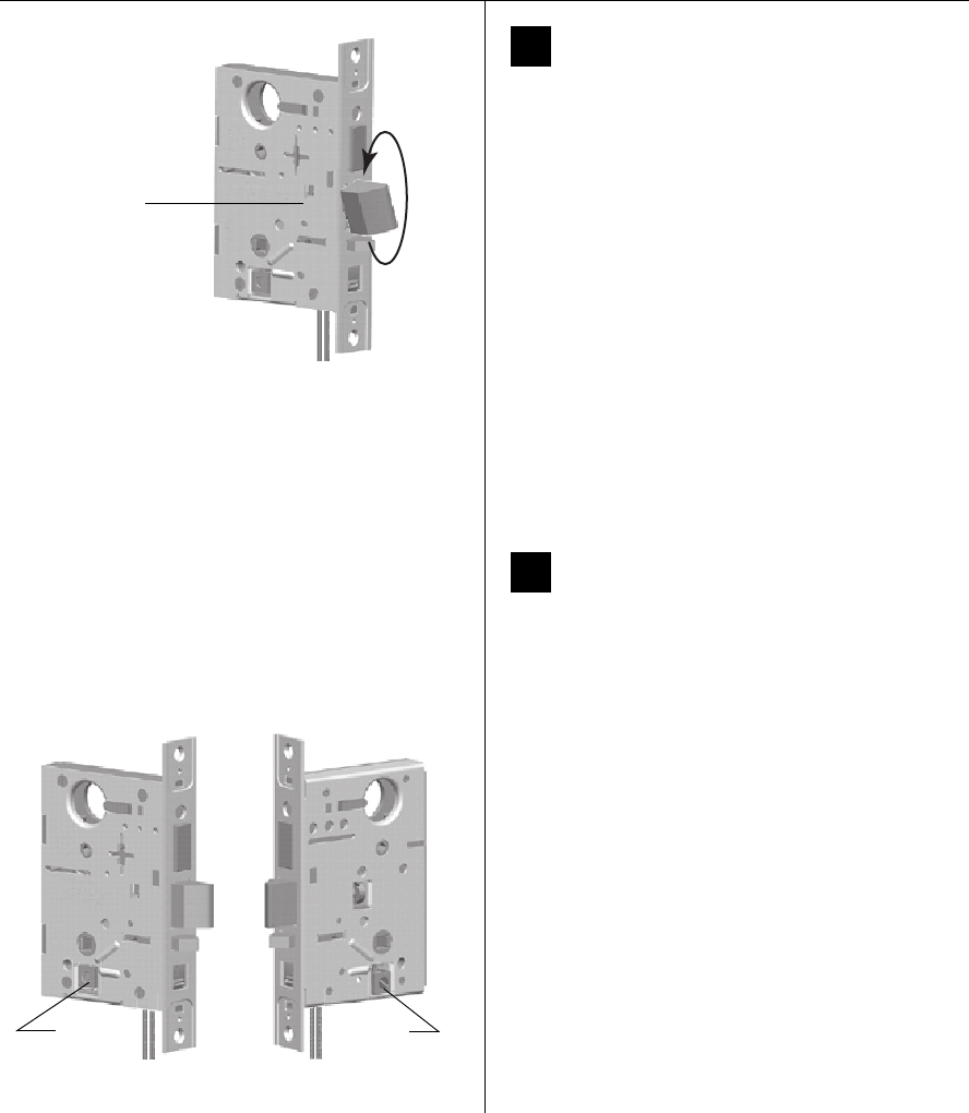
Installation Instructions for 45HW & 47HW Electrified Mortise Locks
BEST ACCESS SYSTEMS
a Division of Stanley Security Solutions, Inc.
Configuring & installing the mortise case
6
9Rotate latchbolt (if necessary)
1 Determine whether you need to rotate the latchbolt to
match the handing of the door.
Note: The angled surface of the latchbolt must contact
the strike when the door closes.
2 If you need to rotate the latchbolt, insert a flat blade
screwdriver into the latch access point approximately
1/2″ into the case and press to extend the latch out of
the case (Figure 9).
3 Rotate the latchbolt 180 degrees and allow it to retract
into the case.
10 Position hub toggles (if necessary)
1 Check whether the hub toggles are in the proper
position for the lock (Figure 10). The inside hub toggle
should be down (always latched) and the outside hub
toggle should be up (lockable).
Note 1: For LH & LHRB doors, the inside is the back side
of the case and the outside is the cover side of the case.
For RH & RHRB doors, the inside is the cover side of the
case and the outside is the back side of the case. The
cover is mounted to the case with 4 screws.
Note 2: If the lock has an optional RQE status sensor,
two RQE status switches are installed in the mortise case.
However, only the switch for the inside of the lock needs
to be connected. Before you install the mortise case in the
door, determine whether you need to connect the ‘Case
Side’ pair of RQE wires or the ‘Cover Side’ pair of RQE
wires, based on the handing of the door.
2 To change the position of a hub toggle, remove the
toggle screw, move the toggle into the desired
position, and re-tighten the screw.
Figure 9 Rotating the latchbolt
Latch access point
Figure 10 Positioning the hub toggles
Hub toggleHub toggle
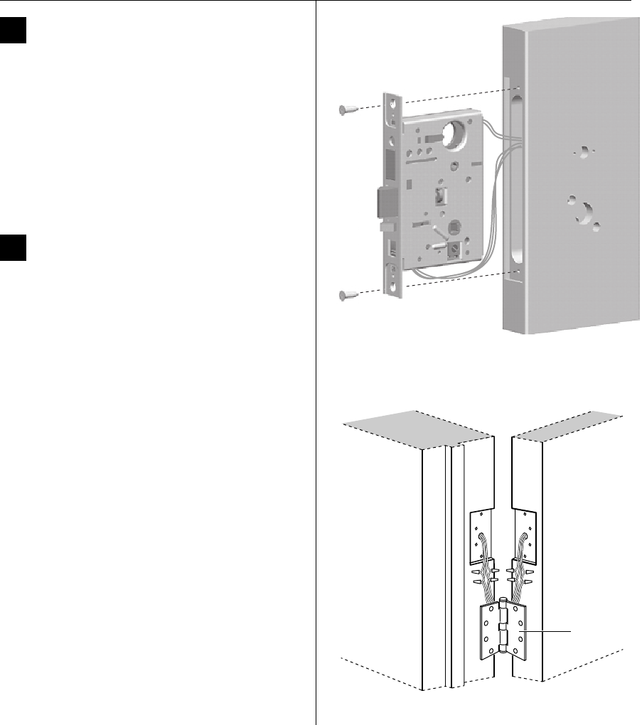
Installation Instructions for 45HW & 47HW Electrified Mortise Locks
BEST ACCESS SYSTEMS
a Division of Stanley Security Solutions, Inc.
7
Installation Instructions for 45HW & 47HW Electrified Mortise Locks
Configuring & installing the mortise case
11 Install mortise case
1 Drill the holes for the case mounting screws.
2 Insert the mortise case into the mortise cavity, feeding
all sensor and solenoid wires into the mortise cavity.
Note: The armored front of the mortise case self-adjusts
to the door bevel.
3 From the hinge edge of the door, fish all sensor and
solenoid wires from the mortise cavity through the
wire channel to the hinge mortise.
4 Secure the mortise case with the case mounting
screws (Figure 11).
12 Install wire transfer hinge
Note: BEST recommends one of the following concealed
electric hinges from Stanley Security Solutions. For more
information, contact your BEST representative.
1 Trim the power and sensor wires that you pulled
through the hinge edge of the door. Leave sufficient
length to connect to the wire transfer hinge and to
allow for future splices.
2 Splice the field wires to the leads on the frame side of
the hinge, following the hinge manufacturer’s
instructions.
3 Splice the power and sensor wires from the lock to the
leads on the door side of the hinge, matching each
lead to its corresponding wire.
Note: If the lock has an optional RQE status sensor,
splice only the pair of RQE wires for the switch on the
inside of the door, which you identified in Task 10 on
page 6. Put the unused pair of RQE wires in the door.
4 Insert the wires and splice connectors into the holes or
pockets in the door and frame, being careful not to
pinch the wires. Install the wire transfer hinge.
Hinge Description†
†All hinges measure 4.5″ × 4.5″ and have a 26D finish. All hinges
have two 24 AWG wires rated for 2 A at 12 or 24 volts (AC or DC)
and four 28 AWG wires rated for 1 A at 12 or 24 volts (AC or DC).
CECB 179-66 Standard weight; steel
CECB 168-66 Heavy weight; steel
CECB 191-66 Standard weight; brass
Figure 11 Installing the mortise case
Figure 12 Installing the wire transfer hinge
Door frame
Wire transfer
hinge
Door
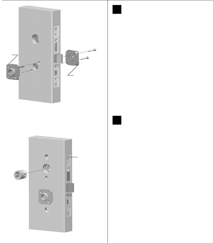
Installation Instructions for 45HW & 47HW Electrified Mortise Locks
BEST ACCESS SYSTEMS
a Division of Stanley Security Solutions, Inc.
Installing the trim
8
13 Install trim mounting plates
1 For J trim, position the J alignment plate (Figure 15b)
on the outside of the door.
2 For all trim, insert the outside trim mounting plate
through the door and mortise case.
3 Position the inside trim mounting plate opposite the
outside trim mounting plate and screw them securely
in place.
Caution: Do not overtighten the trim mounting
plate screws. Overtightening may damage the
locking mechanism.
14 Install concealed cylinder (N trim only)
1 Use a cylinder wrench to thread the cylinder into the
mortise case so that the groove around the cylinder is
even with the door surface.
Caution: A malfunction can occur if the cylinder is
threaded in too far.
2 Secure the cylinder in the mortise case with the
cylinder retainer screw.
Figure 13 Installing the trim mounting plates
Outside
mounting
plate
Inside
mounting
plate
Figure 14 Installing the concealed cylinder
Cylinder
retainer
screw
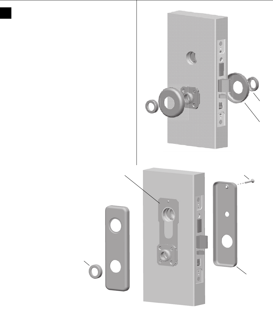
Installation Instructions for 45HW & 47HW Electrified Mortise Locks
BEST ACCESS SYSTEMS
a Division of Stanley Security Solutions, Inc.
9
Installation Instructions for 45HW & 47HW Electrified Mortise Locks
Installing the trim
15 Install roses or escutcheons
For sectional trim (Figure 15a)
1 Position the inside rose on the door so it is centered on
the trim mounting plate.
2 Use the spanner wrench to install the rose ring onto
the inside mounting plate.
3 Position the outside rose on the door so it is centered
on the trim mounting plate.
4 Use the spanner wrench to install the rose ring onto
the outside mounting plate.
For J trim (Figure 15b)
1 Position the inside escutcheon on the door so it is
centered on the trim mounting plate. Install the
escutcheon screw.
2 Use the spanner wrench to install the trim ring onto
the inside mounting plate.
3 Position the outside escutcheon on the door over the
alignment plate.
4 Use the spanner wrench to install the trim ring onto
the outside trim mounting plate.
Figure 15a Installing the roses
Rose
Rose
ring
Figure 15b Installing the J trim escutcheons
Trim ring
Inside
escutcheon
Escutcheon screw
Alignment plate
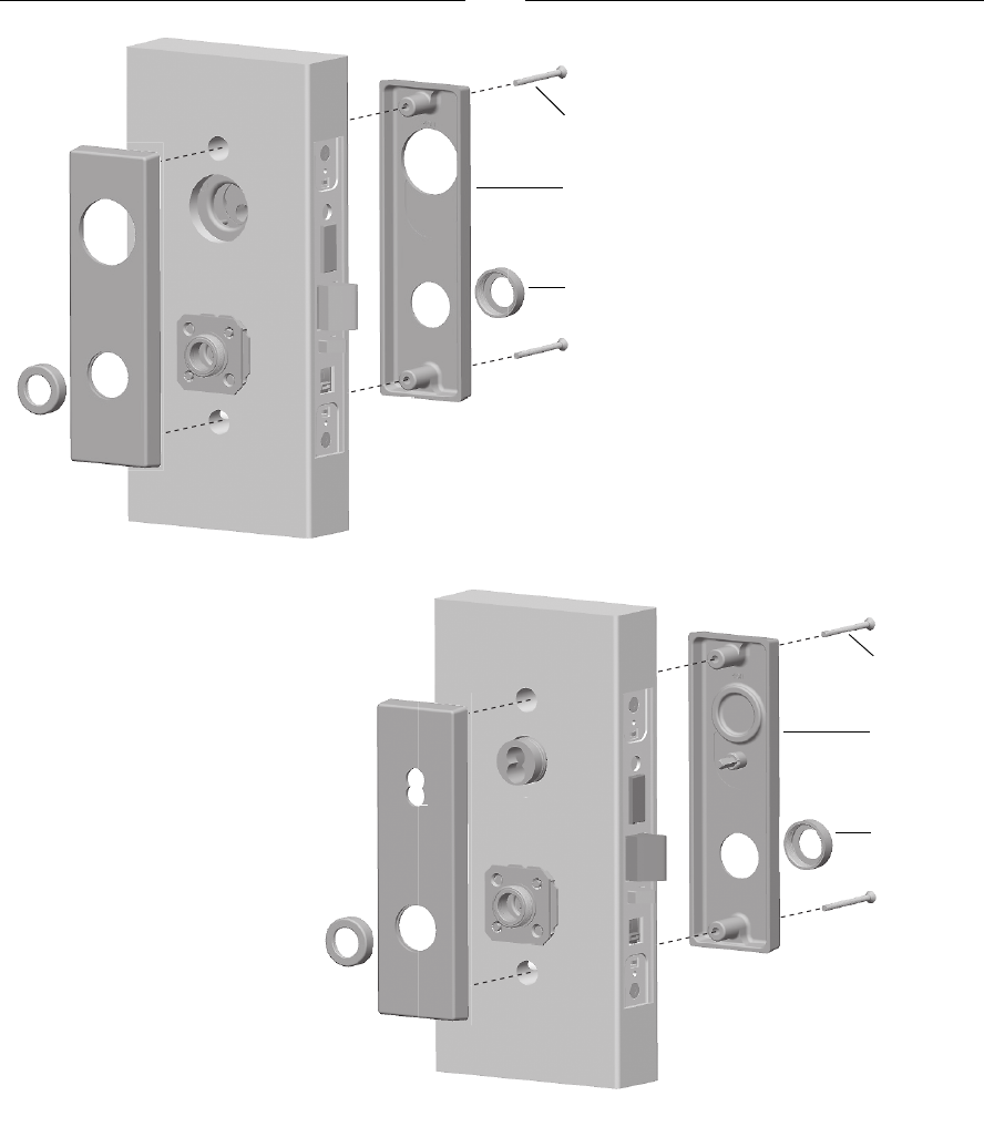
Installation Instructions for 45HW & 47HW Electrified Mortise Locks
BEST ACCESS SYSTEMS
a Division of Stanley Security Solutions, Inc.
Installing the trim
10
For M trim (Figure 15c) or N trim
(Figure 15d)
1 Position the inside and outside
escutcheons on the door so
they are centered on the trim
mounting plates.
2 Install the upper and lower
escutcheon screws from the
inside of the door.
3 Use the spanner wrench to
install the trim rings onto the
inside and outside trim
mounting plates.
Figure 15c Installing the M trim escutcheons
(47H M trim shown)
Escutcheon
screw
Inside
escutcheon
Trim ring
Figure 15d Installing the N trim escutcheons
Escutcheon
screw
Inside
escutcheon
Trim ring
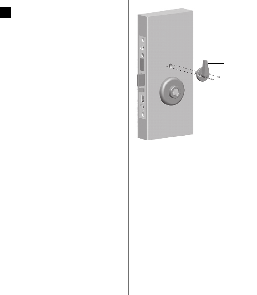
Installation Instructions for 45HW & 47HW Electrified Mortise Locks
BEST ACCESS SYSTEMS
a Division of Stanley Security Solutions, Inc.
11
Installation Instructions for 45HW & 47HW Electrified Mortise Locks
Installing the trim
16 Install thumb turn or emergency
access plate (if necessary)
Note 1: Install the thumb turn on the inside of the door
for the following lock functions:
■TDEL ■TDEU
■LEL ■LEU
Note 2: Install the emergency access plate on the
outside of the door for privacy function (LEL and LEU)
locks.
1 Orient the thumb turn so it points up when the
deadbolt is retracted and towards the hinge edge of
the door when the deadbolt is extended.
2 Install the thumb turn or emergency access plate using
the two screws provided (Figure 16).
Figure 16 Installing the thumb turn or emergency access plate
Thumb turn
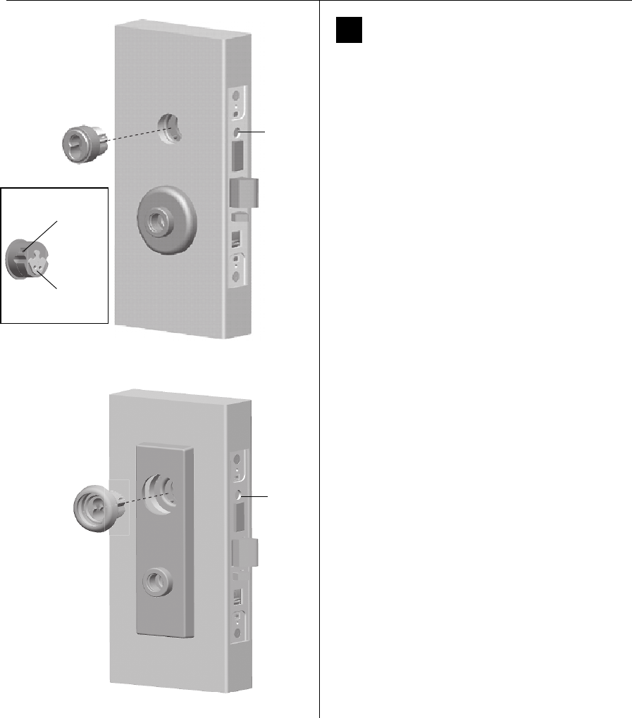
Installation Instructions for 45HW & 47HW Electrified Mortise Locks
BEST ACCESS SYSTEMS
a Division of Stanley Security Solutions, Inc.
Installing the trim
12
17 Install standard or high security
cylinder (if necessary)
1 Using a narrow-blade screwdriver, insert the blade
into the cylinder’s figure-8 opening and back the set
screw into the cylinder until the tip of the set screw is
below the threads of the cylinder.
2 Make sure the washer (standard cylinder only) and
cylinder ring are positioned on the cylinder.
3 Rotate the cylinder cam to the 12 o’clock position.
4 Use a cylinder wrench to thread the cylinder into the
mortise case.
For a standard cylinder, rotate the cylinder until the
cylinder ring is flush against the door.
For a high-security cylinder, rotate the cylinder until the
cylinder head touches the inside rim of the cylinder
ring.
Caution: A malfunction can occur if the cylinder is
threaded in too far.
5 Using a narrow-blade screwdriver, insert the blade
into the figure-8 opening and tighten the small set
screw (installed in the cylinder) into the lock case.
6 Secure the cylinder in the mortise case with the
cylinder retainer screw.
Figure 17a Installing the standard cylinder
Cylinder
retainer
screw
Set
screw
location
Cam in
12 o’clock
position
Back view of cylinder
Figure 17b Installing the high-security cylinder
Cylinder
retainer
screw
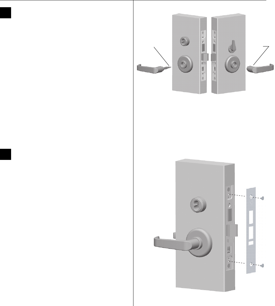
Installation Instructions for 45HW & 47HW Electrified Mortise Locks
BEST ACCESS SYSTEMS
a Division of Stanley Security Solutions, Inc.
13
Installation Instructions for 45HW & 47HW Electrified Mortise Locks
Finishing the installation
18 Install inside and outside levers
For standard lever installation (Figure 18)
1 Unscrew the inside spindle one full turn to allow the
spindles to turn freely.
Note: Remove the label from the inside spindle.
2 With the handle pointing toward the door hinges,
insert the outside lever and spindle assembly into the
lock from the outside of the door.
Note: The 17 style lever is handed. The lever should
curve downward when installed on the door.
3 Slide the inside lever onto the inside spindle and
secure it with the set screw.
4 Turn the levers to check that they operate smoothly.
19 Install mortise case faceplate
1 Secure the mortise case faceplate to the mortise case
with the faceplate mounting screws.
2 Check the lock for proper operation.
Figure 18 Installing the levers
Location
of set
screw
Outside of door Inside of door
Spindle
assembly
Figure 19 Installing the mortise case faceplate
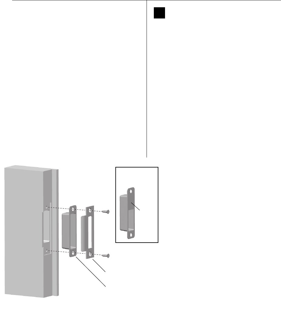
Installation Instructions for 45HW & 47HW Electrified Mortise Locks
BEST ACCESS SYSTEMS
a Division of Stanley Security Solutions, Inc.
Finishing the installation
14
20 Install strike box and strike plate
1 If the door jamb has not been mortised for the strike box
and strike plate, perform these steps:
a On the door jamb, locate the horizontal centerline
of the strike (3/8″ above the centerline of the lock),
as well as the vertical centerline of the strike.
b Mortise the door jamb to fit the strike box and
strike plate.
c Drill the holes for the screws used to install the
strike box and strike plate.
2 If using a strike box with a magnet (for the optional door
status sensor), orient the strike box so that the magnet
is at the top of the strike box.
3 Insert the strike box into the mortise in the door jamb.
Place the strike plate over the strike box and secure the
strike with the screws provided.
4 Check the position of the auxiliary bolt against the
strike plate.
Note: The recommended gap between the door and
jamb is 1/8″.
Figure 20 Installing the strike box and strike plate
Strike
box
Strike
plate
Magnet
Strike box with
magnet
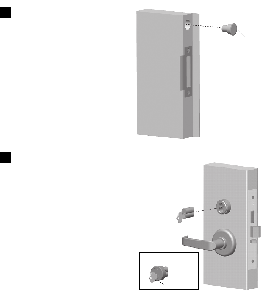
Installation Instructions for 45HW & 47HW Electrified Mortise Locks
BEST ACCESS SYSTEMS
a Division of Stanley Security Solutions, Inc.
15
Installation Instructions for 45HW & 47HW Electrified Mortise Locks
Finishing the installation
21 Install door status magnet
(optional for deadbolt function locks)
1 On the door jamb, mark the drill point for the door
status magnet hole.
Note: This hole should be directly opposite the door
status switch when the door is closed.
2 Drill a 1″ diameter hole for the magnet, at least 1 3/4″
deep.
3 Insert the magnet into the hole.
22 Install cores
1 For a high-security cylinder, slide the cylinder face
down over the core.
2 Insert the control key into the core and rotate the key
15 degrees to the right.
3 With the control key in the core, insert the core and
cylinder face (high-security cylinder only) into the
cylinder.
4 Rotate the control key 15 degrees to the left and
withdraw the key.
Caution: The control key can be used to remove
cores and to access doors. Provide adequate
security for the control key.
Figure 21 Installing the door status magnet
Door
status
magnet
Figure 22 Installing the core(s)
Control key
Core
Cylinder
Cylinder face
View of high-security cylinder

Installation Instructions for 45HW & 47HW Electrified Mortise Locks
BEST ACCESS SYSTEMS
a Division of Stanley Security Solutions, Inc.
16
Finishing the installation
23 Install lock power supply
Determine the power supply requirements for the
lock.
■For a lock with a 12 volt solenoid, use a regulated
power supply rated for 12 volts DC at 1.1 amps.
■For a lock with a 24 volt solenoid, use a regulated
power supply rated for 24 volts DC at 0.75 amps.
■To power more than one lock with the same power
supply, sum the total volt-amps (power) for the
circuit and then multiply that number by 1.5. This is
the minimum power rating in volt-amps
recommended for the power supply.
Example for two locks powered by one supply:
Both locks are rated at 12 volts, 1.1 amps
(12 volts × 1.1 amps) + (12 volts × 1.1 amps) = 26.4 volt-amps
26.4 volt-amps × 1.5 = 39.6 volt-amps
Choose a power supply with a rating of 39.6 volt-amps or
higher.
24 Make sensor connections
Connect the field wiring for the lock sensors to the
access control panel.
Refer to the table below and the manufacturer’s
instructions for the access control panel.
Wire connection Color No. of
wires
Switch
type
Deadbolt status sensor Blue 2 NO†
† Normally open
Door status sensor White 2 NO
Latchbolt status sensor Violet 2 NC‡
‡ Normally closed
RQE status sensor Brown &
Orange
2NO
25 Check operation
1 Supply power to the lock and check its operation. For
example, check that:
■door latches and opens properly
■deadbolt operates properly
■key access works
■door gap is 1/8”
■auxiliary bolt is held inside the case when the door
is closed.
2 When installation of the access control system has
been completed, apply power to the system and check
that the door’s sensors operate properly.
For assistance, contact your local BEST representative.
© 2006 Stanley Security Solutions, Inc. and Stanley Logistics, Inc.
T81612/Rev - 1907197 ER-7991-12 November 2006
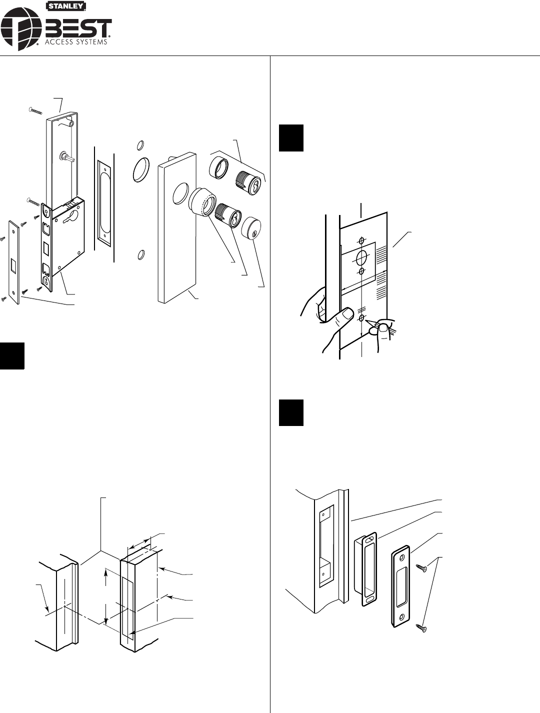
BEST ACCESS SYSTEMS
a Division of Stanley Security Solutions, Inc
Overview
1Mark centerlines
Caution: If you use hollow metal doors, decide whether the
doors are reinforced enough to support the lock. If the door
reinforcement is not adequate, consult the door manufacturer
about proper reinforcement.
Note: Prepare the door according to ANSI A115.1 before using these
instructions.
1 Mark the horizontal centerline of the lock on both sides of the door
and on the door’s edge.
Note: BEST suggests a 38" height as measured from floor to lock center-
line.
2 Mark the vertical centerline of the lock on the door edge.
3 Mark the vertical centerline of the lock on both sides of the door as
measured from the vertical centerline on the door’s edge.
4 Mark the horizontal centerline of the strike on the door jamb in line
with the centerline of the lock.
2Mark drill points
1 Cut the H18 template along the dotted line and align the horizontal
and vertical arrows to the marked centerlines on the door.
2 Tape the template onto the door.
3Install strike
1 Using the H18 template, mortise the jamb and install the strike and
strike box. See Installation Specifications, Template H17 for dimen-
sions.
Figure 1 48H and 49H Mortise Lock overview diagram
Figure 2 Marking the centerlines on the door
Mortise lock
49H inside trim
Faceplate
48H Trim
49H Cylinder face
49H Cylinder
49H Ring
49H Outside
escutcheon
Centerline
of strike
Door to jamb gap: 1/16” to 3/16”
2 3/4” backset
Vertical center-
Horizontal center-
of lock
Vertical center-
line of lock
line of door’s edge
Figure 3 Marking the drill points with the template
Figure 4 Installing the strike box and strike
H18 template
Jamb
Strike box
Strike plate
#8–32 combination
screws
Installation Instructions
for 48H & 49H Mortise Locks
T81175/Rev – ER-7991-19 Nov 2005 1
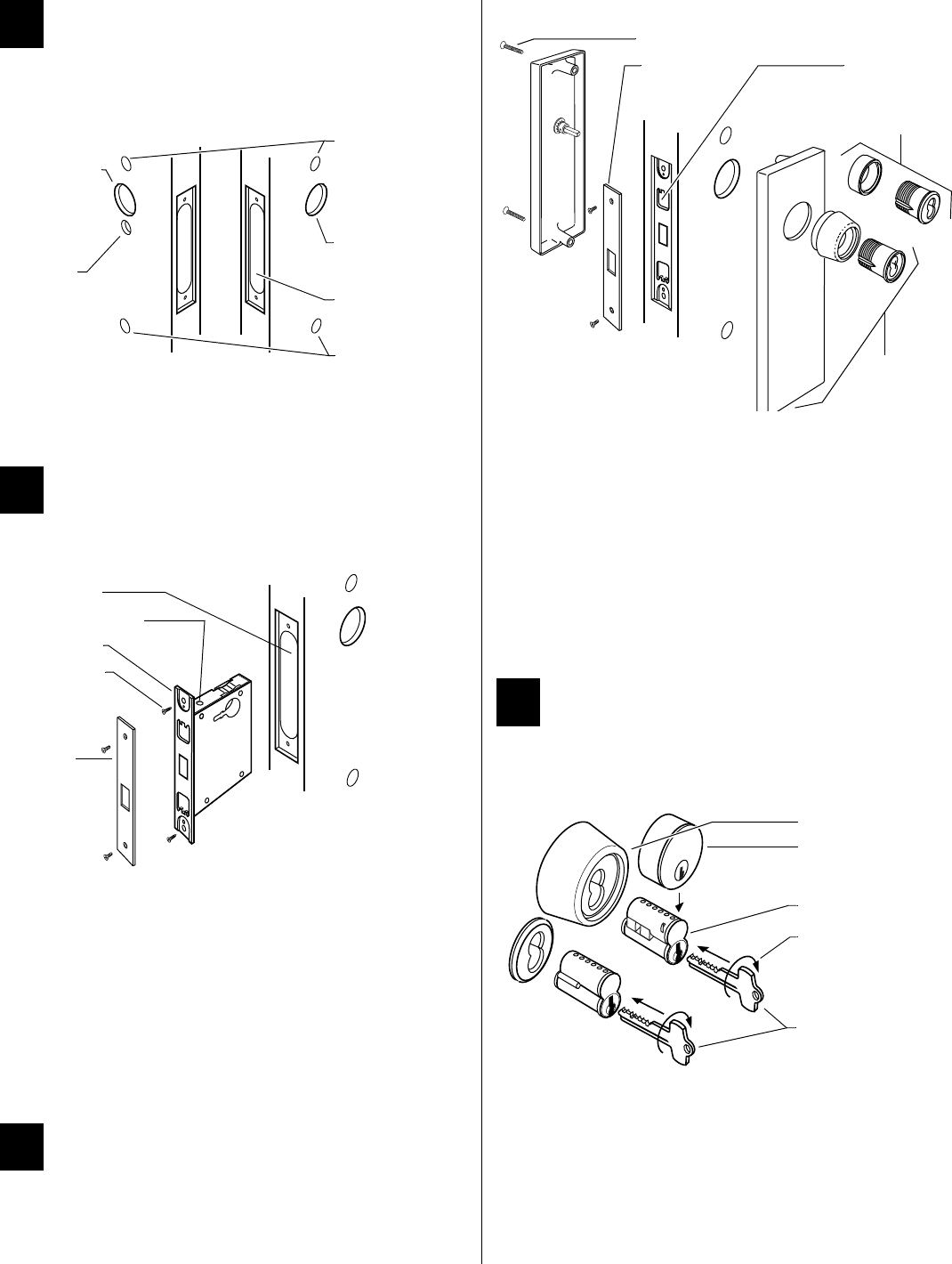
BEST ACCESS SYSTEMS
a Division of Stanley Security Solutions, Inc
4Mortise and drill holes
1 Mortise the door for the lock case and faceplate.
Note: Check the lock for function before drilling.
2 Drill only those holes required for the lock function and trim. See
Installation Specifications for hole requirements in Template H17.
5Install mortise case
1 Remove the faceplate from the lock.
2 Loosen the bevel adjusting screws on the top and bottom of the lock
case and adjust the bevel of the armored front to match the door
bevel. Retighten the screws.
For ‘R’ function only:
■Check the cylinder and lock for proper operation.
Caution: If the handing of the ‘R’ turn knob is incorrect, you can
be locked in.
3 Install the lock into the mortise cavity.
4 Secure the lock case with the case mounting screws.
6Install trim
To install 48H trim:
1 Install cylinder(s) and ring(s) and fasten with cylinder clamp screw(s).
2 Install thumb turn if needed.
3 Reinstall the faceplate.
4 Check the lock for proper operation.
To install 49H trim:
1 Position inside and outside escutcheons opposite each other and
screw them loosely in place.
2 Put the high security cylinder(s) and ring(s) into the cylinder hole(s).
Thread the cylinder(s) into the case until the cylinder head touches
the inside rim of the ring.
3 Secure the cylinder(s) with the cylinder clamp screw(s).
4 Tighten the through-bolts.
5 Reinstall the faceplate.
7Install core
For 5C cores only:
■Slide the cylinder face down over the 5C core.
For all cores:
1 Put the control key into the core (or cylinder face) and turn the key
15 degrees clockwise.
2 Adjust the throw pins if needed, then put the core (and cylinder face)
into the cylinder with the control key.
3 Turn the key 15 degrees counterclockwise and remove the key.
Note: Follow these steps to remove the core also.
Figure 5 Mortising and drilling holes
Figure 6 Installing the mortise case
Escutcheon
hole
Outside cylinder
hole
Mortise for lock
case & faceplate
Escutcheon
hole
Inside cylinder
hole
‘K’ function
turn knob hole
Inside Outside
Mortise cavity
Bevel adjusting screw
Armored front
Case mounting
screws
Faceplate
Figure 7 Installing 48H or 49H trim
Figure 8 Installing the core
Through-bolts
Faceplate Cylinder clamp
screw (inside)
Standard cylinder
& ring (48H)
High-security
cylinder, ring, &
escutcheon (49H)
High security cylinder
Cylinder face
5C core
Turn 15 degrees
Control key

40H Series Service Manual C-1
CINDEX
Numerics
12 V solenoid
part drawings for 45HW & 47HW Locks
4–38
1DT function
function description 3–12
2DT function
function description 3–12
A
A function
case diagram 4–2
case parts list 4–3
function description 3–5
AB function
case diagram 4–14
case parts list 4–15
function description 3–5
accessories for electrified locks 5–31
AD function
case diagram 4–34
case parts list 4–35
function description 3–10
ANSI function designations 3–2 to 3–3
AT function
case diagram 4–4
case parts list 4–5
function description 3–5
auxiliary bolt
part drawings for 45H & 47H Locks 4–2
part numbers for 45H & 47H Locks 4–3
B
B function
case diagram 4–16
case parts list 4–17
function description 3–5
B5 function
case diagram 4–22
case parts list 4–23
function description 3–13
B7 function
case diagram 4–22
case parts list 4–23
function description 3–13
BA function
case diagram 4–18
case parts list 4–19
function description 3–6
BW function
case diagram 4–20
case parts list 4–21
function description 3–6
C
C function
case diagram 4–4
case parts list 4–5
function description 3–8
case and strike dimensions
45H & 47H Locks 1–3
45HW & 47HW Locks 1–5
48H & 49H Locks 1–7

Index
C-2 40H Series Service Manual
case cover
part drawings for 45H &
47H Locks 4–2
part drawings for 48H &
49H Locks 7–3
part numbers for 45H &
47H Locks 4–3
part numbers for 48H &
49H Locks 7–3
case cover mounting screw
part drawings for 45H & 47H
Locks 4–2
part numbers for 45H &
47H Locks 4–3
case mounting screw
part drawings for 48H &
49H Locks 7–3
part numbers for 48H &
49H Locks 7–3
case only locks
components 4–64
how to order 4–62
case sub-assembly
part drawings for 45H &
47H Locks 4–2
part drawings for 48H &
49H Locks 7–3
part numbers for 45H &
47H Locks 4–3
part numbers for 48H &
49H Locks 7–3
certifications and standards 1–1
changing handing for 45H &
47H cases 6–2
changing the function for
UNAB cases 6–6
UNR cases 6–5
UNT cases 6–6
CHB function
case diagram 4–12
case parts list 4–13
function description 3–8
cylinder retainer
part drawings for 45H &
47H Locks 4–2
part numbers for 45H &
47H Locks 4–3
cylinder retainer assembly
part drawings for 45H &
47H Locks 4–2
part numbers for 45H &
47H Locks 4–3
cylinders and cams
how to order 5–20
part numbers for 45H &
47H Locks 5–21
cylinders rings
part numbers for 45H &
47H Locks 5–21
D
D function
case diagram 4–4
case parts list 4–5
function description 3–6
deadbolt
part drawings for 48H &
49H Locks 7–3
part numbers for 48H &
49H Locks 7–3
deadbolt sub-assembly
part drawings for 45H &
47H Locks 4–26
part numbers for 45H &
47H Locks 4–27
deadlocking lever
part drawings for 45H &
47H Locks 4–2
part numbers for 45H &
47H Locks 4–3
deadlocking lever pin
part drawings for 45H &
47H Locks 4–2
part numbers for 45H &
47H Locks 4–3
deadlocking lever spring
part drawings for 45H &
47H Locks 4–2
part numbers for 45H &
47H Locks 4–3
DEL function
case diagram 4–38
case parts list 4–39
function description 3–14
DEU function
case diagram 4–40
case parts list 4–41
function description 3–14
documentation package 1–8
door position clip
part drawings for 45HW &
47HW Locks 4–38
door status switch
part drawings for 45HW &
47HW Locks 4–38
double cylinder clamp plate
part drawings for 48H & 49H
Locks 7–3
part numbers for 48H &
49H Locks 7–3
driver bits 5–30
dummy trim
part drawings for 45H &
47H Locks 5–27
part numbers for 45H &
47H Locks 5–27
E
electrified hub (LH)
part drawings for 45HW &
47HW Locks 4–38
electrified hub (RH)
part drawings for 45HW &
47HW Locks 4–38
electronic locking toggle assembly
part drawings for 45HW &
47HW Locks 4–38
F
F locking lever sub-assembly
part drawings for 45H &
47H Locks 4–12, 4–14
part numbers for 45H &
47H Locks 4–15
faceplate
part drawings for 48H &
49H Locks 7–3
part numbers for 48H &
49H Locks 7–3
faceplate kits
components 5–15
how to order 5–15
faceplate screw
part drawings for 48H &
49H Locks 7–3
part numbers for 48H &
49H Locks 7–3
function
changing for UNAB cases 6–6
changing for UNR cases 6–5
changing for UNT cases 6–6
function descriptions for 45H &
47H Locks
deadlocked functions 3–10
double-keyed functions 3–8
non-keyed functions 3–11
single-keyed functions 3–5
special functions 3–13
understanding function
drawings 3–4

Index
40H Series Service Manual C-3
function descriptions for 45HW &
47HW Locks
electrified functions 3–14
function descriptions for 48H &
49H Locks 7–2
function-specific locks 2–1
fusible link molded assembly
part drawings for 45H &
47H Locks 4–2
part numbers for 45H &
47H Locks 4–3
G
G function
case diagram 4–22
case parts list 4–23
function description 3–8
H
H function
case diagram 4–24
case parts list 4–25
function description 3–6
handing, changing for 45H &
47H cases 6–2
HJ function
case diagram 4–24
case parts list 4–25
function description 3–6
holdback case sub-assembly
part drawings for 45H &
47H Locks 4–12
part number for 45H &
47H Locks 4–13
holdback cover
part drawing for 45H &
47H Locks 4–12
part number for 45H &
47H Locks 4–13
holdback hub
part number for 45H &
47H Locks 4–13
holdback hub-assembly
part drawings for 45H &
47H Locks 4–12
hub
part drawings for 45H &
47H Locks 4–2
part numbers for 45H &
47H Locks 4–3
I
IND function
case diagram 4–26
case parts list 4–27
function description 3–8
INL function
case diagram 4–4
case parts list 4–5
function description 3–9
inside trim kits
components 5–7
how to order 5–6
J
J trim inside escutcheons 5–24
J trim outside escutcheons 5–23
K
K deadlock function
case diagram 7–3
case parts list 7–3
function description 7–2
key release lever
part drawings for 45H &
47H Locks 4–2
part numbers for 45H &
47H Locks 4–3
key release shuttle assembly
part drawings for 45H &
47H Locks 4–2
part numbers for 45H &
47H Locks 4–3
kits, advantages of 2–2
L
L deadlock function
case diagram 7–3
case parts list 7–3
function description 7–2
L function
case diagram 4–28
case parts list 4–29
function description 3–11
latchbolt sensor switch assembly
part drawings for 45HW &
47HW Locks 4–38
latchbolt sub-assembly
part drawings for 45H &
47H Locks 4–2
part numbers for 45H &
47H Locks 4–3
LB function
case diagram 4–30
case parts list 4–31
function description 3–11
LEL function
case diagram 4–58
case parts list 4–59
function description 3–14
LEU function
case diagram 4–60
case parts list 4–61
function description 3–14
lever sets
components 5–13
how to order 5–12
locking lever and toggle assembly
part drawings for 45H &
47H Locks 4–2
part numbers for 45H &
47H Locks 4–3
LT function
case diagram 4–6
case parts list 4–7
function description 3–11
M
M & N trim inside escutcheons
5–26
M & N trim outside escutcheons
5–25
M deadlock function
case diagram 7–3
case parts list 7–3
function description 7–2
modified key release lever
part drawings for 45H &
47H Locks 4–34
part numbers for 45H &
47H Locks 4–35
N
N function
case diagram 4–8
case parts list 4–9
function description 3–11
NX function
case diagram 4–10
case parts list 4–11
function description 3–11
NXEL function
case diagram 4–46
case parts list 4–47
function description 3–15

Index
C-4 40H Series Service Manual
NXEU function
case diagram 4–48
case parts list 4–49
function description 3–15
O
outside trim kits
components 5–3
how to order 5–2
overview
45H & 47H Locks 1–2
45HW & 47HW Locks 1–4
48H & 49H Locks 1–6
R
R deadlock function
case diagram 7–4
case parts list 7–4
function description 7–2
R function
case diagram 4–4
case parts list 4–5
function description 3–6
RD function
case diagram 4–36
case parts list 4–37
function description 3–10
release lever spring
part drawings for 45H &
47H Locks 4–2
part numbers for 45H &
47H Locks 4–3
release lever sub-assembly
part drawings for 45H &
47H Locks 4–2
part numbers for 45H &
47H Locks 4–3
replacement spindles
components 5–17
how to order 5–16
RHB function
case diagram 4–12
case parts list 4–13
function description 3–7
roses and rose rings
part drawings for 45H &
47H Locks 5–27
part numbers for 45H &
47H Locks 5–27
RQE and latch status switch assem-
bly
part drawings for 45HW &
47HW Locks 4–38
RQE switch assembly (case side)
part drawings for 45HW &
47HW Locks 4–38
RQE switch assembly (cover side)
part drawings for 45HW &
47HW Locks 4–38
S
S function
case diagram 4–18
case parts list 4–19
function description 3–9
screw kits
components 5–19
how to order 5–18
self tapping screw
part drawings for 45H &
47H Locks 4–20
part numbers for 45H &
47H Locks 4–21
service equipment 5–29, 5–31
spacer for 38/39H
part drawings for 4–34
part numbers for 4–35
spindles
See replacement spindles
strain relief
part drawings for 45HW &
47HW Locks 4–38
strike packages
components 5–11
how to order 5–10
strikes and strike boxes for 48H &
49H Locks 7–7
support, technical 1–8
T
T function
case diagram 4–26
case parts list 4–27
function description 3–7
TA function
case diagram 4–32
case parts list 4–33
function description 3–7
TD function
case diagram 4–24
case parts list 4–25
function description 3–7
TDEL function
case diagram 4–50
case parts list 4–51
function description 3–15
TDEU function
case diagram 4–52
case parts list 4–53
function description 3–15
technical documentation package
1–8
technical support 1–8
three-part locks 2–2
toggle lever
part drawings for 45H &
47H Locks 4–2
part numbers for 45H &
47H Locks 4–3
toggle lever spring
part drawings for 45H &
47H Locks 4–2
part numbers for 45H &
47H Locks 4–3
toggle roller
part drawings for 45H &
47H Locks 4–2
part numbers for 45H &
47H Locks 4–3
tools 5–29, 5–31
trim kits
See outside trim kits and inside
trim kits
trim kits, working with 2–4
trim one side locks 2–6
trim parts for 48H Locks 7–5
trim parts for 49H high security
deadbolt locks 7–6
troubleshooting
45H & 47H Locks 6–7
48H & 49H Locks 7–8
turn knob hub
part drawings for 45H &
47H Locks 4–2, 4–4,
4–26, 4–36
part drawings for 48H &
49H Locks 7–3 to 7–4
part number for 45H &
47H Locks 4–13
part numbers for 45H &
47H Locks 4–3, 4–5,
4–27, 4–37
part numbers for 48H &
49H Locks 7–3 to 7–4
turn knob hub cam
part drawings for 45H &
47H Locks 4–26
part numbers for 45H &
47H Locks 4–27

Index
40H Series Service Manual C-5
turn knob hub spacer
part drawings for 45H &
47H Locks 4–2
part drawings for 48H &
49H Locks 7–3
part numbers for 45H &
47H Locks 4–3
part numbers for 48H &
49H Locks 7–3
TWEL function
case diagram 4–54
case parts list 4–55
function description 3–16
TWEU function
case diagram 4–56
case parts list 4–57
function description 3–16
U
universal functions, working with
2–2
universal locks 2–2
V
visual indicator trim
part drawings for 45H &
47H Locks 5–28
part numbers for 45H &
47H Locks 5–28
W
W function
case diagram 4–4
case parts list 4–5
function description 3–9
ways to order 40H Locks 2–1
WD function
case diagram 4–34
case parts list 4–35
function description 3–10
WEL function
case diagram 4–42
case parts list 4–43
function description 3–16
WEU function
case diagram 4–44
case parts list 4–45
function description 3–16
wire strain relief
part drawings for 45HW &
47HW Locks 4–38
X
XR function
case diagram 4–4
case parts list 4–5
function description 3–13
Y
YD function
case diagram 4–34
case parts list 4–35
function description 3–10
Z
ZD function
case diagram 4–4
case parts list 4–5
function description 3–13

Index
C-6 40H Series Service Manual
