BIO CONTROL MEDICAL 0010 Programming Wand User Manual RU 53 001 RevH Physician Programmer IFU
BIO CONTROL MEDICAL (B.C.M.) LTD. Programming Wand RU 53 001 RevH Physician Programmer IFU
UserManual.wiki
>
BIO CONTROL MEDICAL
>
0010 User Manual
Users Manual
Navigation menu
Upload a User Manual
Namespaces
Wiki Guide
HTML
PDF
Info
Views
User Manual
Discussion / Help
Navigation
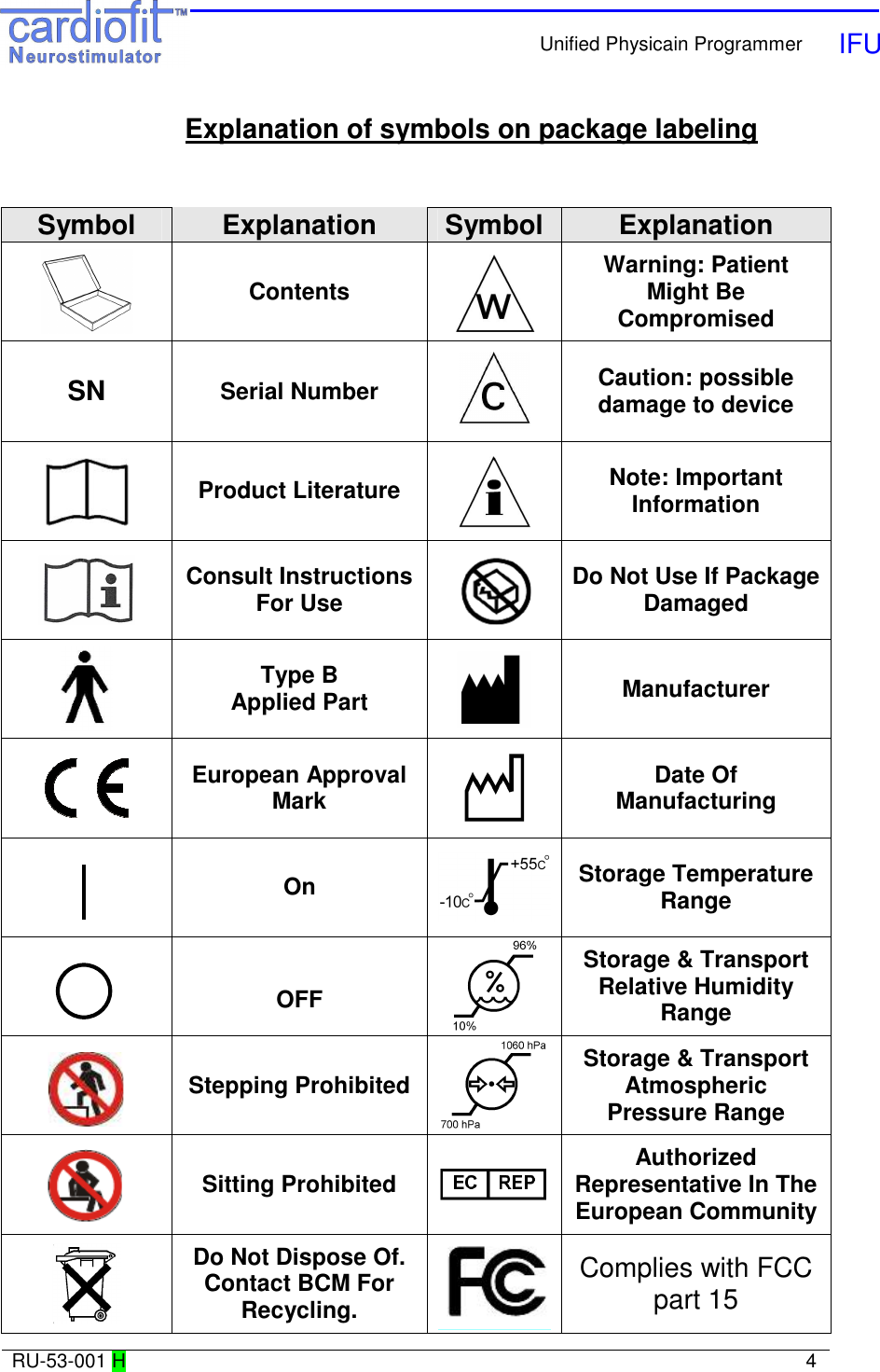
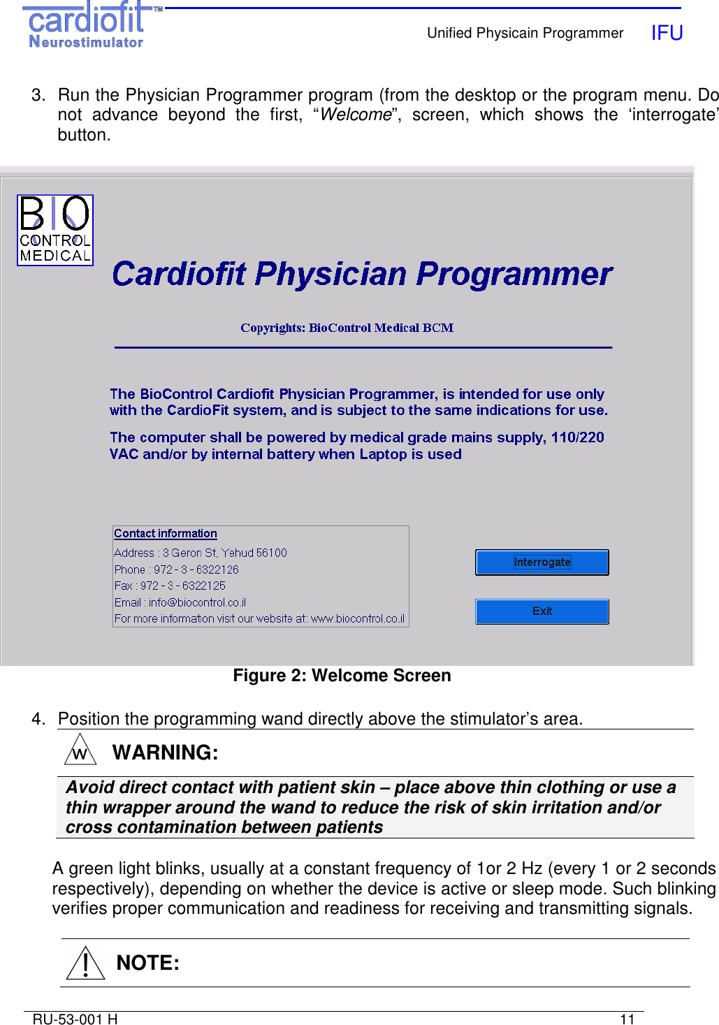
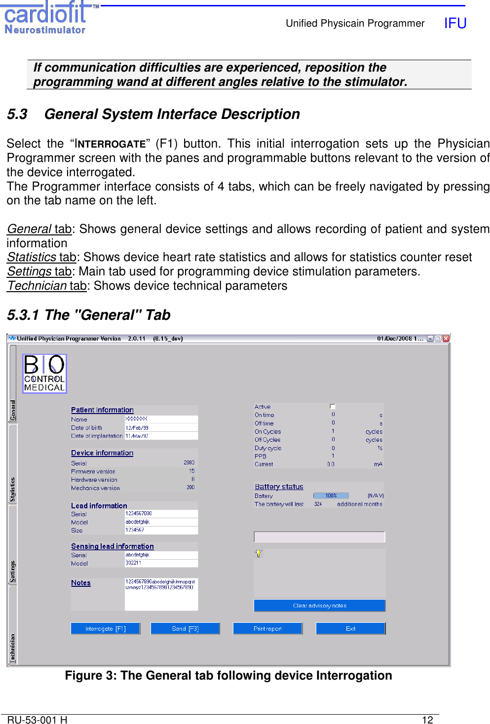
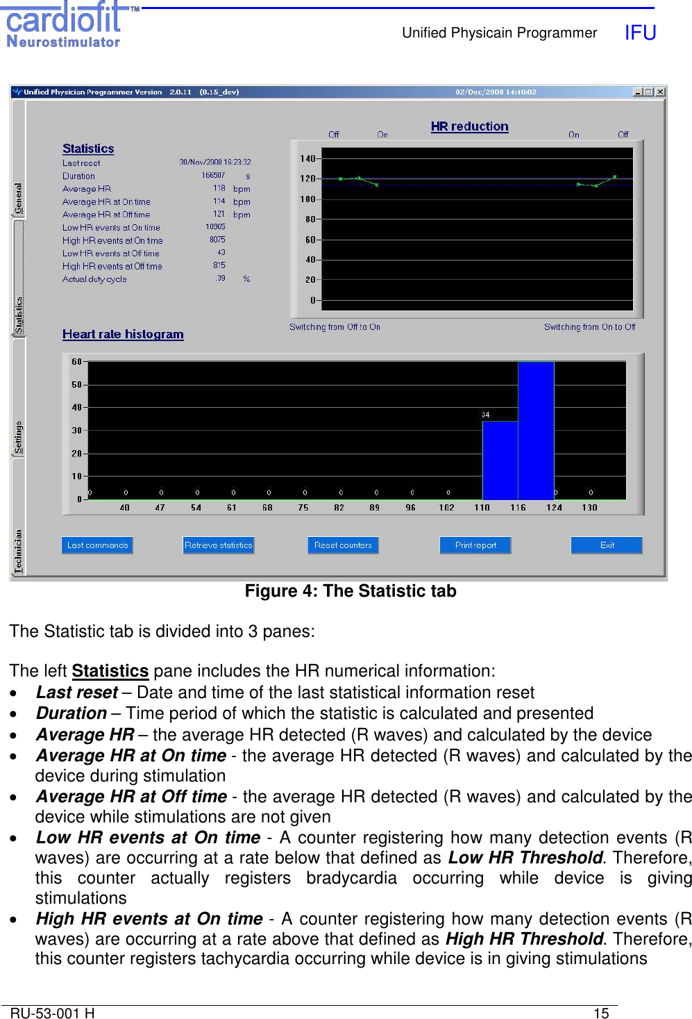
![Unified Physicain Programmer IFU RU-53-001 H 14 Pressing the “Clear Advisory Notes” button will clear advisory notes The bottom pane includes 4 buttons: Interrogate [F1] Device Interrogation provides current device settings. Interrogation checks the parameters of the device and presenting the current values of all programmable buttons. The interrogate function does not change parameters stored in the stimulator Send [F3] In order to communicate updates of programmable buttons press this button. It will also perform interrogation and update output parameters such as counters. Print Report Generates a hardcopy report with device parameters. Create an image file (*.JPG) in which major counters values and the latest display graph are presented. The image file will be created on a connected external removable drive (disk-on-key). After pressing the ‘print report’ a separate window will appear. The image file will be placed in a subdirectory “NNNN” in the external removable disk where “NNNN” is the device serial number. File name: “Report__NNNN_YYYY-MM-DD_hh-mm-ss.jpg” NNNN is the device serial number. YYYY-MM-DD is the creation date, in year/month/day format. hh-mm-ss is the creation time, in 24h format. Example: a report was printed on 18 May 2010 at 1:53 pm for device 2812, where the external disk drive letter is E: The report will be in file: E:\2812\Report_2812_2010-05-18_13-53-00.jpg Exit Exits the Physician Programmer and returns to Windows These 4 buttons also appear in setting tab and have similar functions 5.3.2 The "Statistic" tab; Therapy evaluation. The UniPP calculates and analyses the stimulation parameter setting effect on patient heart, thus enabling evaluation of optimal therapy setting. Measures are presented numerically and graphically.](https://usermanual.wiki/BIO-CONTROL-MEDICAL/0010/User-Guide-1068118-Page-14.png)
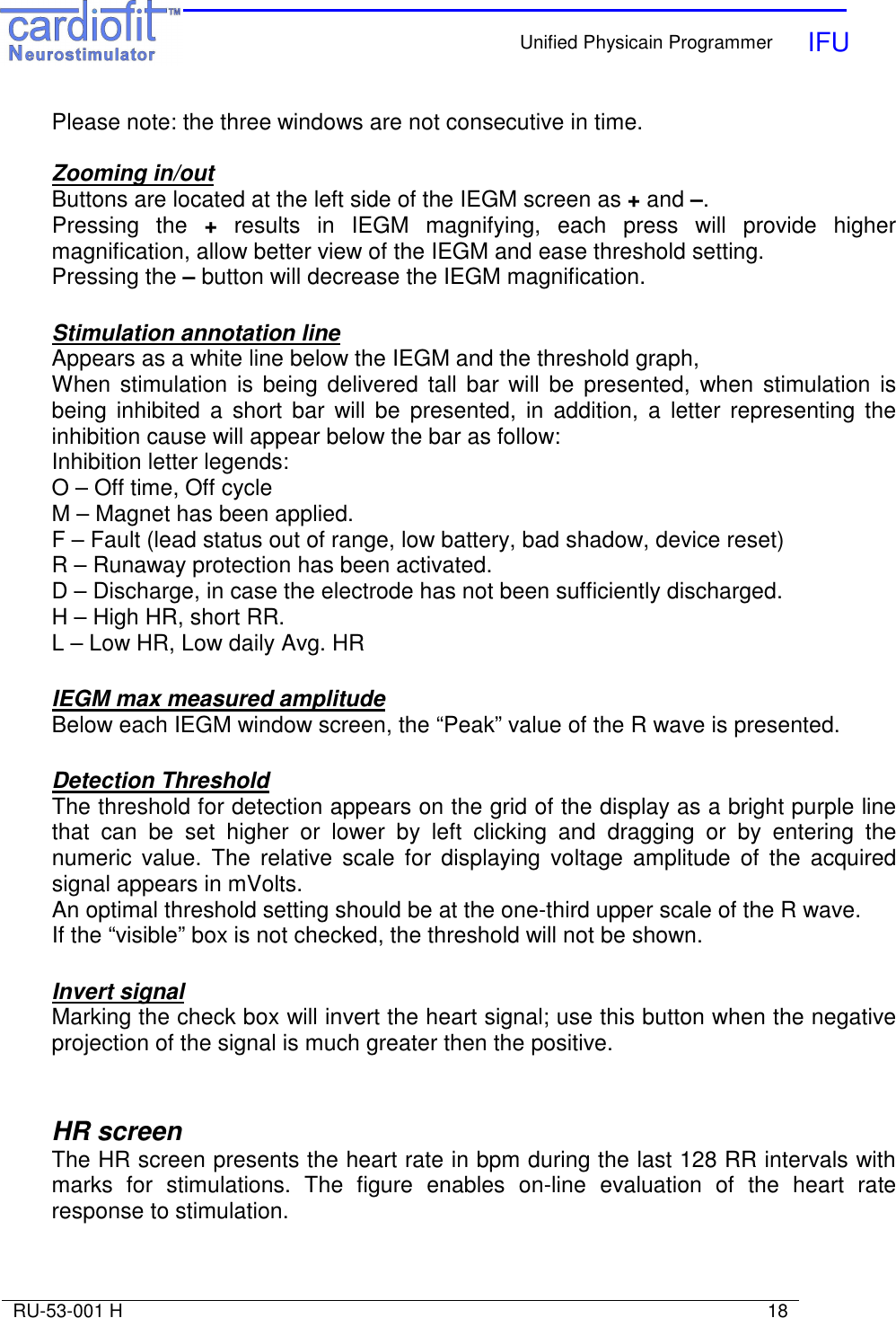
![Unified Physicain Programmer IFU RU-53-001 H 19 Figure 6: The HR Setting tab View HR storage [F8] Button is located at the right pane of the setting screen Pressing this button will display a graph of heart rate of the last 128 RR intervals. Every such heartbeat is marked by a green dot on the graph. Stimulated R waves will be marked in bigger dots. Zooming in/out Marking the desired area in the graph to be zoom-in while left click in the “mouse” will provide focused area of interest. Repeat the procedure for higher magnification if required. Right click will reset the axis scale. The bottom pane of the “setting” tab includes stimulation parameters setting: Stimulation Settings: Active](https://usermanual.wiki/BIO-CONTROL-MEDICAL/0010/User-Guide-1068118-Page-19.png)
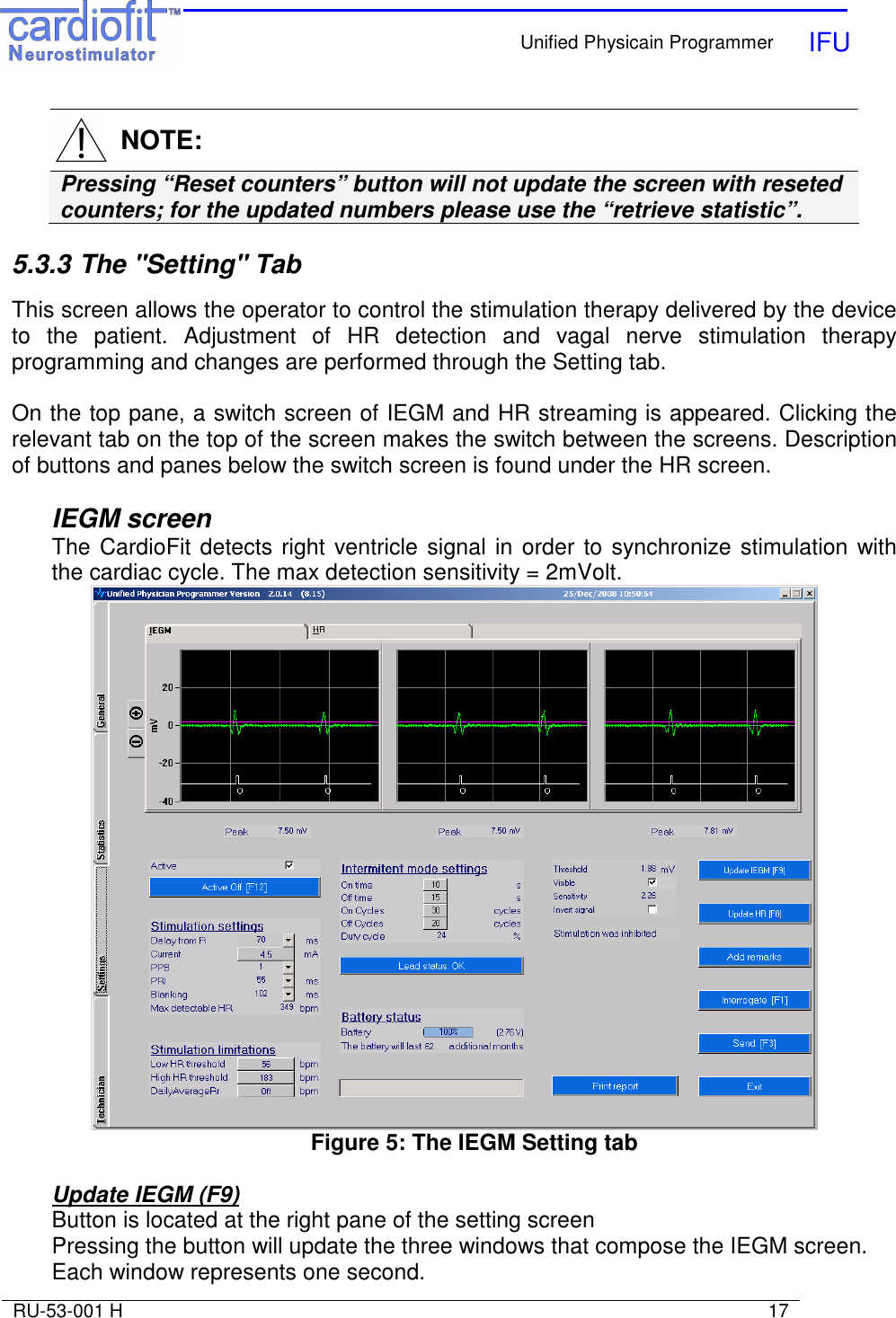
![Unified Physicain Programmer IFU RU-53-001 H 25 When a button is pressed or a new parameter is typed a light blue box will appear around it, until the button “Send” [F3] has been pressed. It is possible to program several parameters together and then press the “Send’ button. Range and default of programmed parameters list: Parameter Range Default On Time [sec] 0…(1)…10…(5)…255 0 Off Time [sec] 0…(1)…10…(5)…255 0 PPB 1, 2, 3 1 Current [mA] 0…(0.1)…6 0 PRI [mSec] 16, 55, 148, 250, 350 55 On Cycles 0…(1)…127 1 Off Cycles 0…(1)…127 0 Low Stimulation Limit [BPM] 30…(4)…320 56 High Stimulation Limit [BPM] Off, 30…(4)…320 150 Daily Average HR Off, 30.1 - 7680 0ff Blanking [mSec] 8…(8)…1000 102 Delay from R wave 0…(8)…1000mSec 70 Detection Threshold (mV) 1.88 to 39.69 39.69 Detection Thresholds sensitivity (mV) ≥2 39.69 6 THERAPY SETTING AND OPTIMIZATION PROGRAM WARNING: The Physician Programmer should be used only by authorized and trained personal NOTE: Make sure the programming wand is correctly positioned over the stimulator, and a green blinking light appears. Hold the programming wand in place until the transmitted parameters had been programmed. NOTE:](https://usermanual.wiki/BIO-CONTROL-MEDICAL/0010/User-Guide-1068118-Page-25.png)
![Unified Physicain Programmer IFU RU-53-001 H 27 • Switch to the "Statistic" tab and press the "retrieve statistic" button. Review the last interval heart rate outcome. • Set therapy parameters • After the last parameter setting change, follow the patient for any discomfort for at least 30 minutes before release. 6.5 Parameter setting process • Use the "Setting" tab in the UniPP for setting parameters • Verify that "active" button is marked • HR wave detection: Press the IEGM tab to view IEGM and than press the "Update IEGM" [F9]. Verify correct signal threshold for detection. Detection thresholds should be set to the 2/3 amplitude of R wave. Minimum sensitivity is 2 mV. • At the first activation of the device set the parameters as indicated in following table. Parameter Value On Time [sec] 10 Off Time [sec] 15 PPB 1 Current [mA] 0.1 PRI [mSec] 250 On Cycles 30 Off Cycles 20 Low Stimulation Limit [BPM] 56 High Stimulation Limit [BPM] 130 Daily Average HR Off Blanking [mSec] 70 Delay from R wave 250 • Increase current in steps of 0.2 mA and press "Send [F3]" button. Allow patient to adjust the change for 5 minutes. • When the patient detects stimulation, ask him/her to determine the stimulation sensation level. If the sensation is intolerable, wait for at least 15 minutes before proceeding. In case that sensation level does not decrease, reduce current in 0.1 mA steps until comfortable sensation of stimulation is achieved. Set the final parameters for the optimization session accordingly. • Continue with the same procedure at each optimization session up to 5.5 mA and continuously evaluate the effect of the stimulation setting on iHRR. 6.6 Instantaneous HRR evaluation and PPB/ON time change iHRR can be observed at the "Statistic" tab: HR statistic, HR reduction figure and HR distribution histogram for the last interval and in the "Setting" tab: HR figure • ON Time setting change;](https://usermanual.wiki/BIO-CONTROL-MEDICAL/0010/User-Guide-1068118-Page-27.png)
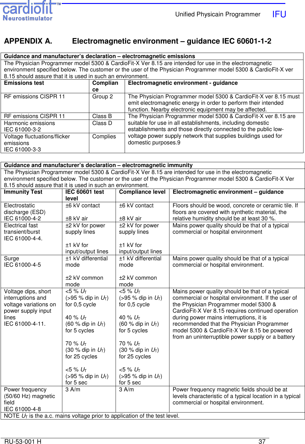
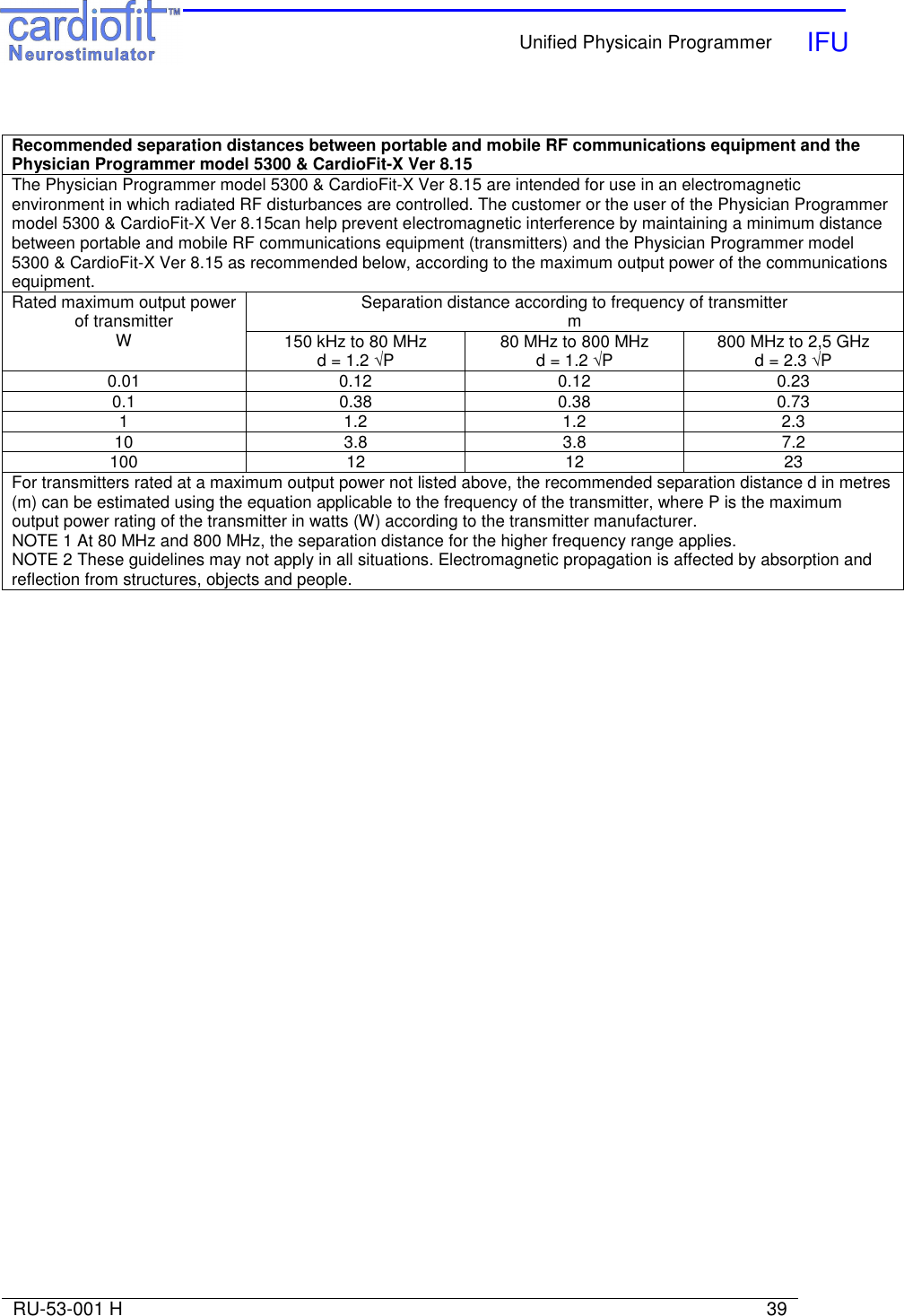
![Unified Physicain Programmer IFU RU-53-001 H 38 Guidance and manufacturer’s declaration – electromagnetic immunity The Physician Programmer model 5300 & CardioFit-X Ver 8.15 are intended for use in the electromagnetic environment specified below. The customer or the user of the Physician Programmer model 5300 & CardioFit-X Ver 8.15 should assure that it is used in such an environment. Immunity Test IEC 60601 test level Compliance level Electromagnetic environment – guidance Portable and mobile RF communications equipment should be used no closer to any part of the Physician Programmer model 5300 & CardioFit-X Ver 8.15, including cables, than the recommended separation distance calculated from the equation applicable to the frequency of the transmitter. Recommended separation distance Conducted RF IEC 61000-4-6 3 Vrms 150 kHz to 80 MHz 3 V d = 1.2 √P Radiated RF IEC 61000-4-3 3 V/m 80 MHz to 2,5 GHz 3 V/m d = 1.2 √P 80 MHz to 800 MHz d = 2.3 √P 800 MHz to 2,5 GHz where P is the maximum output power rating of the transmitter in watts (W) according to the transmitter manufacturer and d is the recommended separation distance in metres (m). Field strengths from fixed RF transmitters, as determined by an electromagnetic site survey,a should be less than the compliance level in each frequency range.b Interference may occur in the vicinity of equipment marked with the following symbol: NOTE 1 At 80 MHz and 800 MHz, the higher frequency range applies. NOTE 2 These guidelines may not apply in all situations. Electromagnetic propagation is affected by absorption and reflection from structures, objects and people. a Field strengths from fixed transmitters, such as base stations for radio (cellular/cordless) telephones and land mobile radios, amateur radio, AM and FM radio broadcast and TV broadcast cannot be predicted theoretically with accuracy. To assess the electromagnetic environment due to fixed RF transmitters, an electromagnetic site survey should be considered. If the measured field strength in the location in which the Physician Programmer model 5300 & CardioFit-X Ver 8.15 are used exceeds the applicable RF compliance level above, the Physician Programmer model 5300 & CardioFit-X Ver 8.15 should be observed to verify normal operation. If abnormal performance is observed, additional measures may be necessary, such as reorienting or relocating the Physician Programmer model 5300 & CardioFit-X Ver 8.15 b Over the frequency range 150 kHz to 80 MHz, field strengths should be less than [V1] V/m.](https://usermanual.wiki/BIO-CONTROL-MEDICAL/0010/User-Guide-1068118-Page-38.png)