BIO CONTROL MEDICAL 0020 PROGRAMMING WAND User Manual RU 53 001 Revk Physician Programmer IFU clean
BIO CONTROL MEDICAL (B.C.M.) LTD. PROGRAMMING WAND RU 53 001 Revk Physician Programmer IFU clean
UserManual.wiki
>
BIO CONTROL MEDICAL
>
0020 User Manual
Users Manual
Navigation menu
Upload a User Manual
Namespaces
Wiki Guide
HTML
PDF
Info
Views
User Manual
Discussion / Help
Navigation
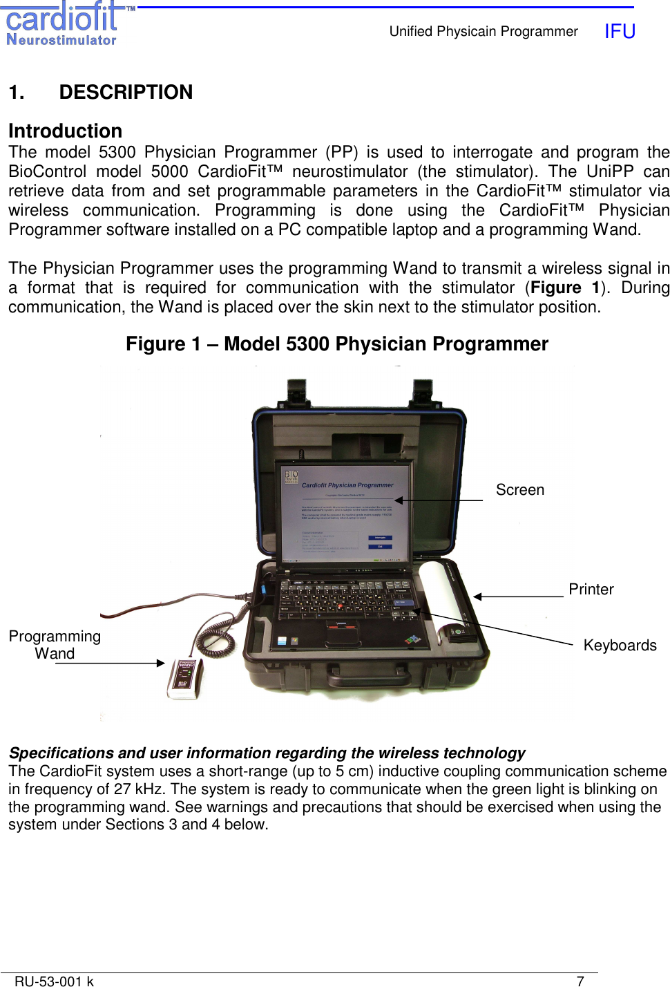
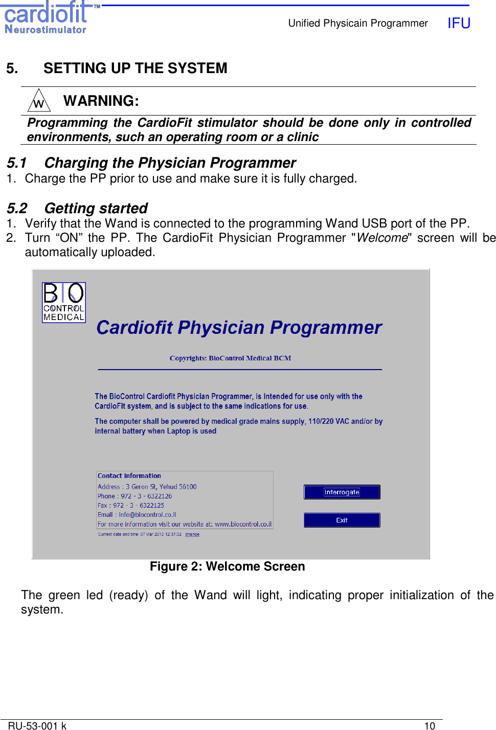
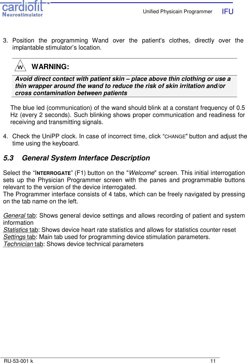
![Unified Physicain Programmer IFU RU-53-001 k 13 • Sensing lead information Serial number - An editable text view up to 32 characters. Model - An editable text view up to 32 characters. • Notes An editable text view which can be used at the physician’s discretion The right pane includes: • An overview of current device settings including Activity status: On time, Off time, On cycles, Off cycles, Duty cycle, PPB, Current • Battery status and estimated running time. For a detailed description of these parameters, please see section 5.3.3, The Settings tab. • Advisory Notes Advisory notes will appear in case the CIS has experienced one of the following conditions: • Battery voltage is too low • Indication of insufficient discharge of stimulation electrode was given • Indication from runaway protection mechanism was given • CardioFit performed reset • Bad memory shadow indication was given • Magnet was applied to disable stimulation • High/low impedance indication was given . Actions that should be taken following each advisory note are described in section 9 Pressing the “Clear Advisory Notes” button will clear advisory notes The bottom pane includes 4 buttons: Interrogate [F1] Device Interrogation provides current device settings. Interrogation checks the parameters of the device and presents the current values of all programmable buttons and includes last measured RR interval. The interrogate function does not change parameters stored in the stimulator Send [F3] Press this button in order to communicate and apply the parameter setting changes. It will also perform interrogation and update output parameters such as counters.](https://usermanual.wiki/BIO-CONTROL-MEDICAL/0020/User-Guide-1263137-Page-13.png)
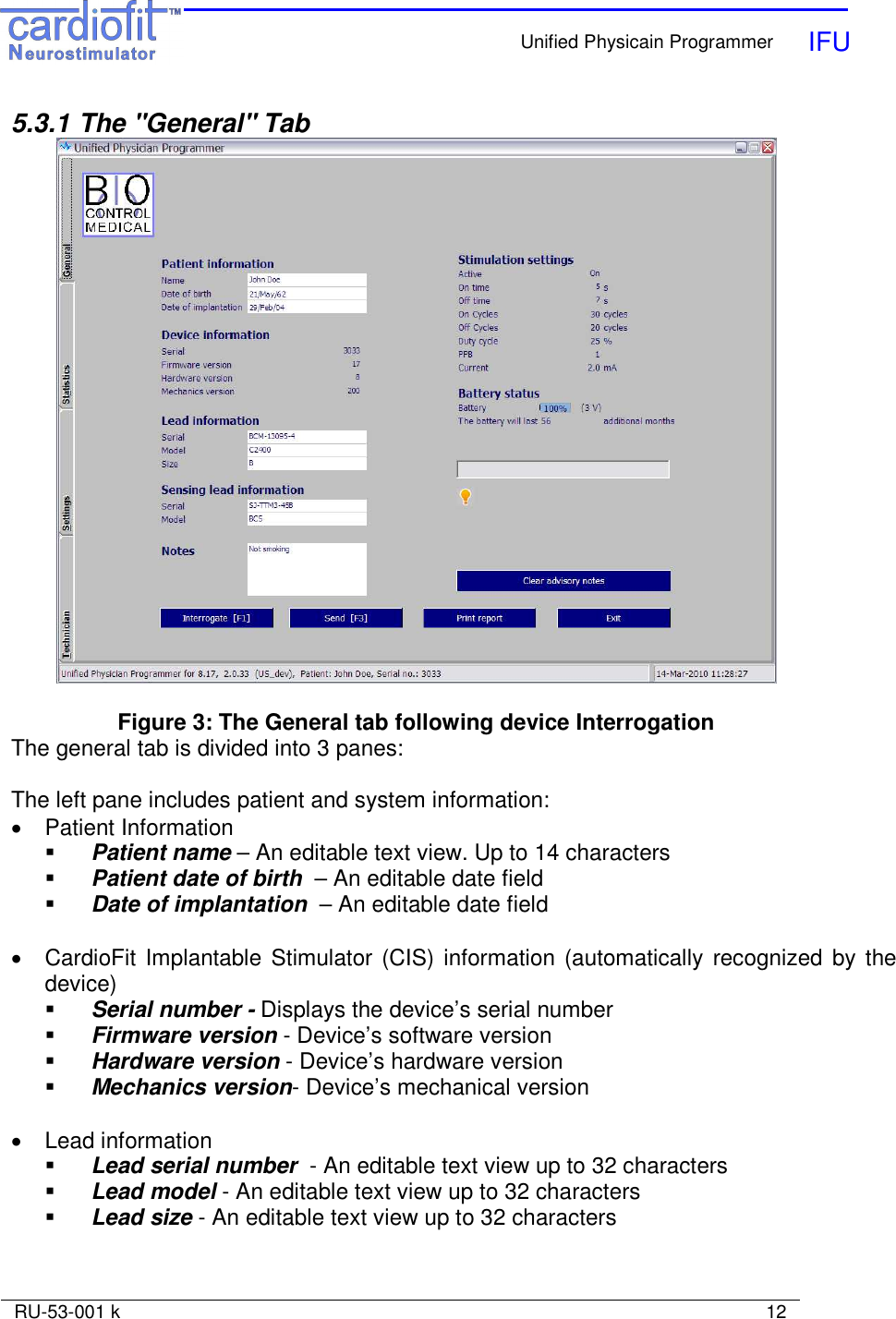
![Unified Physicain Programmer IFU RU-53-001 k 14 Print Report This button generates a hardcopy report with device parameters. After pressing the ‘PRINT REPORT’ button, the image file will be ready for printing. Single click on the Power button will turn on the printer. Double clicks will turn it off. Figure 4: A Sample Print Report Exit Exits the Physician Programmer. NOTE: Before exiting the PP and ending the visit with the patient, it is recommended to save the device logs onto a USB memory stick for further off- line analysis of the therapy when it is required. Plug the memory stick to the USB port and press Ctrl+Alt+L button on the UniPP Keyboard WARNING: Format the USB memory stick prior to use with the Physician Programmer These 4 buttons (Interrogate [F1], Send [F3], Print Report, and Exit) appear also in the setting tab and have similar functions.](https://usermanual.wiki/BIO-CONTROL-MEDICAL/0020/User-Guide-1263137-Page-14.png)
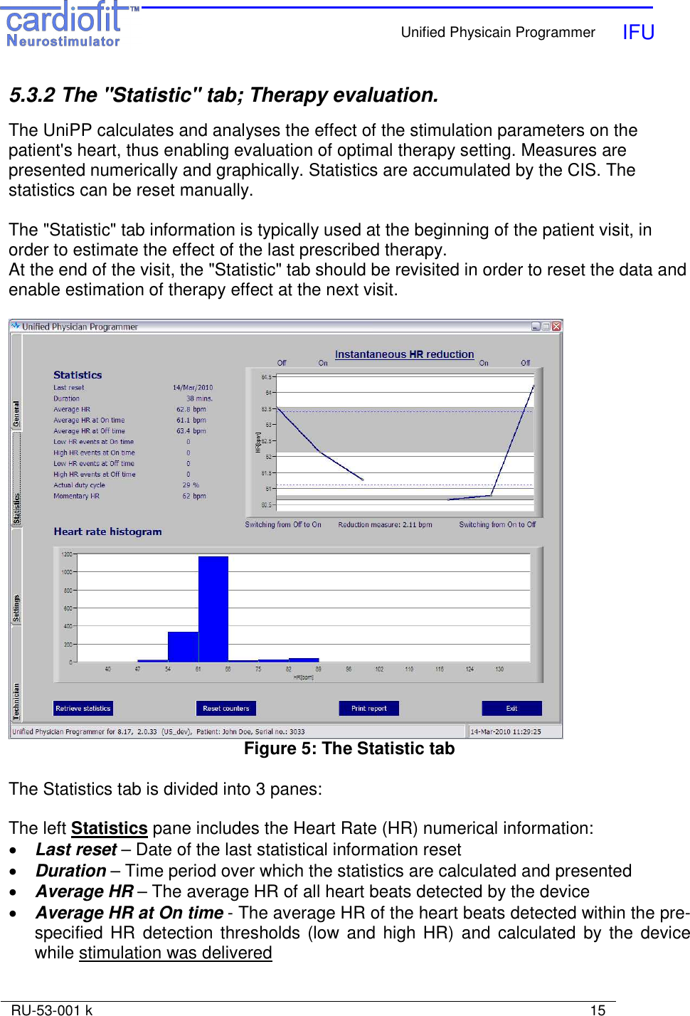
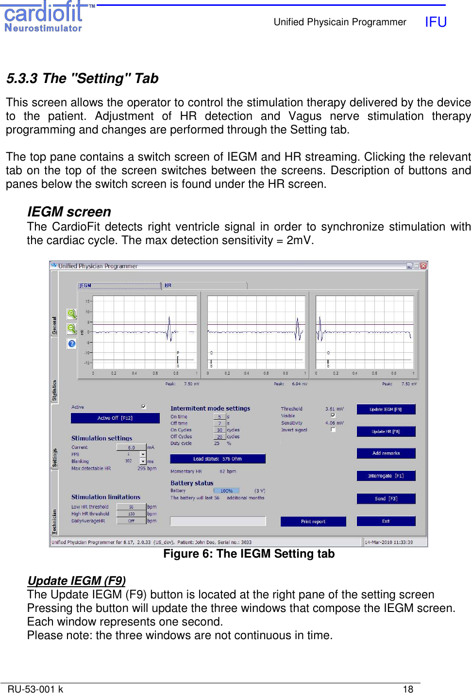
![Unified Physicain Programmer IFU RU-53-001 k 20 Figure 7: The HR Setting tab Update HR [F8] This button is located at the right pane of the setting screen Pressing this button will display a graph of heart rate of the last 128 RR intervals. Every such heartbeat is marked by a green dot on the graph. Stimulated R waves will be marked in larger dots. Zooming in/out Marking the desired area in the graph to be zoomed-in while left clicking the “mouse” will provide focused area of interest. Repeat the procedure for higher magnification if required. Right click will reset the axis scale. The bottom pane of the “Setting” tab includes stimulation parameters settings: Stimulation Settings: Active Check box may be un-checked in order to inactivate the device. In the ‘non active’ mode the CIS is not sensing or counting and not stimulating. When the box is checked the CIS is activated.](https://usermanual.wiki/BIO-CONTROL-MEDICAL/0020/User-Guide-1263137-Page-20.png)
![Unified Physicain Programmer IFU RU-53-001 k 21 Current Sets the amplitude of the current provided by the stimulation lead in milliamps (mA). Value can only be selected from a table appearing when button is left-clicked, as a safety measure. Current should not be increased by more than 0.2mA at one time. The default value is 0mA, max value is 6mA. PPB Pulses Per Beat will set a constant number of pulses per single heartbeat. Max PPB value is 3 in regular use and 8 in implantations (only appear in the CardioFit-X version). The following table specifies stimulation interval duration from at each specified PPB PPB actual PPB Delay From R [ms] Pulse Repetition Interval [ms] 1 1 94 8 2 2 8 86 3 3 8 39 Blanking Determines the duration of blanking period following stimulation. The purpose of blanking during which there is no detection, is to prevent T wave detection, as well as to prevent the stimulation itself from causing misdetection. Range: 8 ~ 1000 ms in 7-8ms steps. It appears in the IEGM as uncolored line area. The default value is 102ms. Max detectable heart rate The number appearing is the maximum regular beats, or more precisely - Intracardiac signals, per minute that may be detected. This value is the product of several variables, including: PPB, and blanking. The ‘Max detectable HR’ field becomes red if the programmed ‘High HR Threshold’ is greater than 90% of the max detection rate. WARNING: If the High HR Threshold is higher than the Max detectable HR, the device may not be able to prevent stimulation when it is resulted from detection of noisy signal](https://usermanual.wiki/BIO-CONTROL-MEDICAL/0020/User-Guide-1263137-Page-21.png)
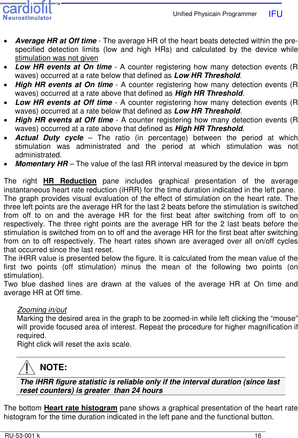
![Unified Physicain Programmer IFU RU-53-001 k 25 Figure 9: Predicted device life time as function of current and PPT The nominal predicted lifetime of the CardioFit™ Implantable Stimulator battery in the maximal therapeutic setting is 4.5 years and the minimum is 3.0 years. The nominal predicted lifetime is calculated under the following conditions: Stimulation electrode Impedance: 1740Ω; Capacitance: 4.7µF Stimulation current: 5mA, 3 pulses per beat, Average HR: 100bpm, Stimulation duty cycle: 25%. Print Report See section 5.3.1 Add Remarks Adds a line in the log file, on which user remarks may be written. Emergency button [F12] This button function is to switch the device to an active off mode without the need of pressing the "send" button, use this button when there is need to terminate the device function immediately. Exit Exits the Physician Programmer and returns to Windows.](https://usermanual.wiki/BIO-CONTROL-MEDICAL/0020/User-Guide-1263137-Page-25.png)
![Unified Physicain Programmer IFU RU-53-001 k 26 NOTE: When a button is pressed or a new parameter is typed a light blue box will appear around it, until the button “Send” [F3] has been pressed. It is possible to program several parameters one after the other and then press the “Send’ button. Range and default of programmed parameters list: Parameter Range Default On Time [s] 0…(1)…10…(5)…255 0 Off Time [s] 0…(1)…10…(5)…255 0 PPB 1, 2, 3 1 Current [mA] 0…(0.1)…6 0 On Cycles 0…(1)…127 1 Off Cycles 0…(1)…127 0 Low Stimulation Limit [BPM] 30…(4)…320 56 High Stimulation Limit [BPM] Off, 30…(4)…320 150 Daily Average HR Off, 30.1 - 7680 0ff Blanking [ms] 8…(8)…1000 102 Detection Threshold [mV] 1.88 to 39.69 39.69 Detection Thresholds sensitivity [mV] ≥2 39.69 6. THERAPY SETTING AND OPTIMIZATION PROGRAM WARNING: The Physician Programmer should be used only by authorized and trained personal NOTE: Make sure the programming wand is correctly positioned over the stimulator, and a green light+ blue blinking light appears. Hold the programming wand in place until the transmitted parameters had been programmed.](https://usermanual.wiki/BIO-CONTROL-MEDICAL/0020/User-Guide-1263137-Page-26.png)
![Unified Physicain Programmer IFU RU-53-001 k 28 o Electrocardiogram from most updated 12-lead ECG/Holter. Identify any new significant abnormalities (Heart rate, conduction, arrhythmias, etc.) • Interrogate the device and review the information appeared in the "General" tab of the UniPP. Identify any parameter settings discrepancy or system malfunctions. • Switch to the "Statistic" tab and press the "retrieve statistic" button. Review the last interval heart rate outcome and compare it with the previous results. • Set therapy parameters • After the last parameter setting change, follow the patient for any discomfort for at least 30 minutes before release. 6.5 Parameter setting process • Use the "Setting" tab in the UniPP for setting parameters • Verify that "active" button is marked • HR wave detection: Press the IEGM tab to view IEGM and than press the "Update IEGM" [F9]. Verify correct signal threshold for detection. Detection thresholds should be set to the 2/3 amplitude of R wave. Minimum sensitivity is 2 mV. • At the first activation of the device set the parameters as indicated in following table. Parameter Value On Time [s] 10 Off Time [s] 15 PPB 1 Current [mA] 0.1 On Cycles 30 Off Cycles 20 Low Stimulation Limit [BPM] 56 High Stimulation Limit [BPM] 130 Daily Average HR Off Blanking [ms] 70 • Increase current in steps of 0.2 mA and press "Send [F3]" button. Allow patient to adjust the change for 5 minutes. • When the patient detects stimulation, ask him/her to determine the stimulation sensation level. If the sensation is intolerable, wait for at least 15 minutes before proceeding. In case that sensation level does not decrease, reduce current in 0.1 mA steps until comfortable sensation of stimulation is achieved. Set the final parameters for the optimization session accordingly.](https://usermanual.wiki/BIO-CONTROL-MEDICAL/0020/User-Guide-1263137-Page-28.png)
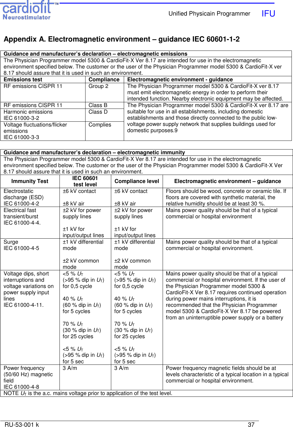
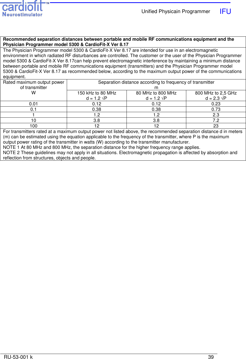
![Unified Physicain Programmer IFU RU-53-001 k 38 Guidance and manufacturer’s declaration – electromagnetic immunity The Physician Programmer model 5300 & CardioFit-X Ver 8.17 are intended for use in the electromagnetic environment specified below. The customer or the user of the Physician Programmer model 5300 & CardioFit-X Ver 8.17 should assure that it is used in such an environment. Immunity Test IEC 60601 test level Compliance level Electromagnetic environment – guidance Portable and mobile RF communications equipment should be used no closer to any part of the Physician Programmer model 5300 & CardioFit-X Ver 8.17, including cables, than the recommended separation distance calculated from the equation applicable to the frequency of the transmitter. Recommended separation distance Conducted RF IEC 61000-4-6 3 Vrms 150 kHz to 80 MHz 3 V d = 1.2 √P Radiated RF IEC 61000-4-3 3 V/m 80 MHz to 2,5 GHz 3 V/m d = 1.2 √P 80 MHz to 800 MHz d = 2.3 √P 800 MHz to 2,5 GHz where P is the maximum output power rating of the transmitter in watts (W) according to the transmitter manufacturer and d is the recommended separation distance in meters (m). Field strengths from fixed RF transmitters, as determined by an electromagnetic site survey,a should be less than the compliance level in each frequency range.b Interference may occur in the vicinity of equipment marked with the following symbol: NOTE 1 At 80 MHz and 800 MHz, the higher frequency range applies. NOTE 2 These guidelines may not apply in all situations. Electromagnetic propagation is affected by absorption and reflection from structures, objects and people. a Field strengths from fixed transmitters, such as base stations for radio (cellular/cordless) telephones and land mobile radios, amateur radio, AM and FM radio broadcast and TV broadcast cannot be predicted theoretically with accuracy. To assess the electromagnetic environment due to fixed RF transmitters, an electromagnetic site survey should be considered. If the measured field strength in the location in which the Physician Programmer model 5300 & CardioFit-X Ver 8.17 are used exceeds the applicable RF compliance level above, the Physician Programmer model 5300 & CardioFit-X Ver 8.17 should be observed to verify normal operation. If abnormal performance is observed, additional measures may be necessary, such as reorienting or relocating the Physician Programmer model 5300 & CardioFit-X Ver 8.17 b Over the frequency range 150 kHz to 80 MHz, field strengths should be less than [V1] V/m.](https://usermanual.wiki/BIO-CONTROL-MEDICAL/0020/User-Guide-1263137-Page-38.png)