BIO CONTROL MEDICAL 0020 PROGRAMMING WAND User Manual RU 53 001 Revk Physician Programmer IFU clean
BIO CONTROL MEDICAL (B.C.M.) LTD. PROGRAMMING WAND RU 53 001 Revk Physician Programmer IFU clean
Users Manual
B
IO
C
ONTROL
M
EDICAL
BCM
L
TD
I
NSTRUCTIONS
F
OR
U
SE
D
OC
N
O
. RU-53-001 R
EV
. K
S
UBJECT
:
U
NIFIED
P
HYSICIAN
P
ROGRAMMER
Page 1 of 40
M
ODIFICATION
I
NSTRUCTION
N
O
.: M
ODIFICATION
D
ATE
:
10/03/10
M
ODIFICATION
D
ESCRIPTION
: Update to PP software and application instructions per ECO
172 and CardioFit 8.17 changes
I
SSUED BY
T
ITLE
D
ATE
S
IGNATURE
D
UDU
R
IGLER
D
IRECTOR OF
C
LINICAL
A
FFAIRS
10/03/10
A
PPROVAL LIST
N
AME
T
ITLE
D
ATE
S
IGNATURE
T
SACHI
C
ZACZKES
D
IRECTOR
O
F
E
NGINEERING
S
HAI
A
YAL
D
IRECTOR
O
F
D
EVELOPMENT
T
AMIR
S
HEFER
D
IRECTOR OF
Q
UALITY
A
SSURANCE
R
AMI
B
IRAN
VP
R
EGULATORY
&
C
LINICAL
A
FFAIRS
V
ERSION
N
AME
D
ATE
ECO
N
O
: M
ODIFICATION
D
ESCRIPTION
A A
RI
K
EREN
-Y
AAR
06/08/2006 --- First Issue
B A
RI
K
EREN
-Y
AAR
31/10/2006 --- Editorial Changes
C A
RI
K
EREN
-Y
AAR
11/12/2006 --- Addition of buttons; add
applicable icons and
authorized representative
D Y
ITZHAK
S
INAI
01/02/2007 136 Update of device and
software to 7.14
E L
EVY
I
TSIK
15/03/2007 --- Changes According TO ITL
Remarks.
F R
OMANO
A
VINOAM
05/05/2008 153 Update to software 1.0.105
G L
EVY
I
TSIK
15/08/2008 KEMA
2103063
Adding battery lifetime
contour; list of
abbreviations; clarification
of terms and warnings
H D
UDU
R
IGLER
28/12/2008 KEMA
2103063-
17.9.08
Addition of follow-up
requirements; RF and FCC
symbols and text Addition of
ICD compliance; updating to
software 1.0.14; updating
troubleshooting and EMC
requirements.
I D
UDU
R
IGLER
24/03/09 167 Layout Review; Editorial
Changes; Type BF applied
part.

J D
UDU
R
IGLER
4/06/09
151
(additional
items not
identified
before) +
165
Update 8.16 version and
software 2.0.31:
(1) impedance measurement
details (DI#002 in 5.3.3);
(2) indication on inhibition due
to magnet application
(DI#004 in 5.3.1)
(3) estimation on HRR during
on time (DI#005, USRM#11
in 5.3.2)
(4) histogram of pt. HR
(DI#006 in 5.3.2, 5.3.3, 6.6)
(5) Explanation on low and
high HR thresholds
(DI#007/008 in 5.3.3)
(6) Clarification of parameter
setting in the existence of
CRM implantable devices
(in 7)
(7) Remove US IDE indications
and labeling (in 2)
(8) Interrogation includes the
last measured RR interval
(DI#165/009 in 5.3.1, 5.3.2)
(9) Update GUI according to
usability report
(USRM#1/#4)
K D
UDU
R
IGLER
10/03/10 172
Layout Review; Editorial
Changes; Update 8.176
version and software 2.0.33:
(1) Use of USB programming
Wand
(2) Communication indicators,
USRM#38
(3) Inserting the printer in the
system content
(4) Training indication per
USRM#2
(5) Update GUI screens
(6) Impedance rage and
accuracy
(7) Reduce PPB setting for use
without CRMs.
(8) Update battery longevity
information following 3-
years of shelf life
(9) Change to FCC class A
(10) Update
troubleshooting
Neurostimulator For Heart Failure Therapy
PHYSICIAN PROGRAMMER
MODEL 5300
INSTRUCTIONS FOR USE (IFU)
CAUTION – Investigational Device. Limited By Federal Law To Investigational
Use
0344
Physician Programmer
IFU
RU-53-001 k 4
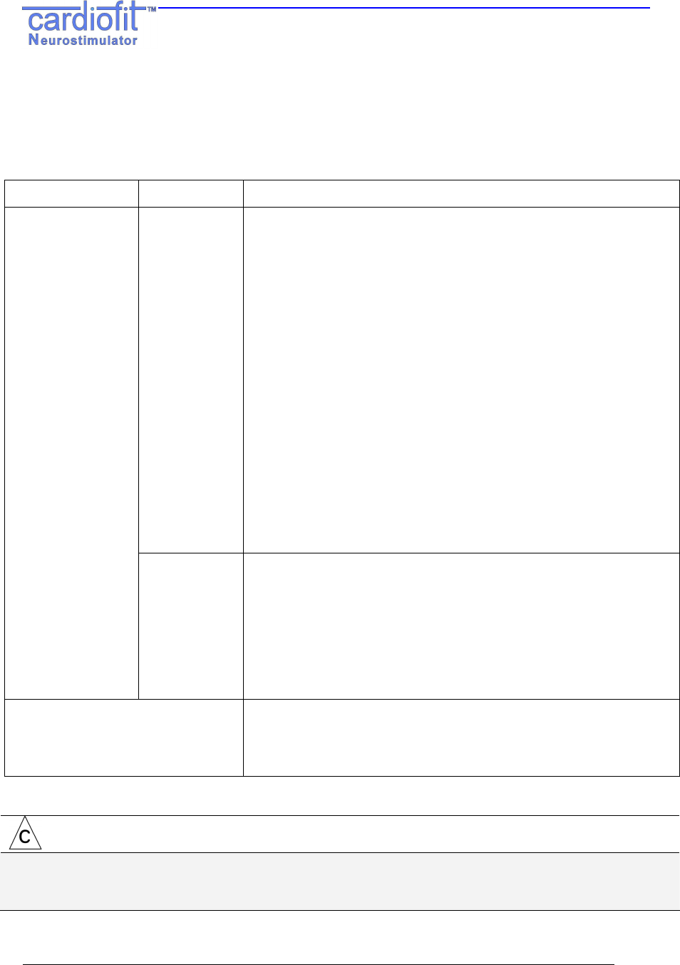
Explanation of symbols in labeling
Symbol Explanation Symbol Explanation
Contents
Warning:
Patient Might Be
Compromised
SN
Serial Number
Caution:
Possible damage to device
Product
Literature
Note: Important Information
Consult Instructions
For Use
Do Not Use If Package
Damaged
Type BF
Applied Part
Manufacturer
European Approval
Mark
Date Of Manufacturing
On
Storage Temperature Range
OFF
Storage & Transport Relative
Humidity Range
Stepping Prohibited
Storage & Transport
Atmospheric Pressure
Range
Sitting Prohibited
Authorized Representative In
The European Community
Do Not Dispose Of.
Contact BCM For
Recycling.
Complies with FCC part 15
Contains RF
transmitters

Unified Physicain Programmer
IFU
RU-53-001 k 5
CONTENTS:
1.
Description 7
2.
Intended Use / Indication 8
3.
Precautions 8
4.
Warnings 9
5.
Setting Up The System 10
5.1
Charging the Physician Programmer 10
5.2
Getting started 10
5.3
General System Interface Description 11
5.3.1
The "General" Tab 12
5.3.2
The "Statistic" tab; Therapy evaluation. 15
5.3.3
The "Setting" Tab 18
6.
Therapy Setting and Optimization Program 26
6.1
General 27
6.2
Therapy Optimization Goal 27
6.3
Communication rules with the patient 27
6.4
Visit Activities Flow 27
6.5
Parameter setting process 28
6.6
Instantaneous HRR evaluation and PPB/ON time change 29
7.
Interactions With Cardiac Implantable Devices 30
7.1
Implanting CardioFit with another cardiac implanted device in the same patient 30
7.2
Programming device parameters 30
7.3
Patient follow-up 32
8
Maintanance, Handling, and Storage 32
8.1
Maintenance 32
8.2
Handling 33
8.3
Storage 33
9. Troubleshooting 34
10.
Product Information and Support 36
11.
Disclaimer Of Warranty 36
Appendix A. Electromagnetic environment – guidance IEC 60601-1-2 37

Unified Physicain Programmer
IFU
RU-53-001 k 6
List of Abbreviations
Abbreviation Explanation
BCM BioControl Medical
CIS CardioFit™ Implanted Stimulator
CRT-D Cardiac Resynchronization Therapy - Implantable
Cardioverter - Defibrillators
CSL CardioFit™ Stimulation Lead
EMI Electromagnetic interference
HR / BPM Heart Rate / Beats Per Minute
ICD Implantable Cardioverter-Defibrillators, Single,
or Dual chamber
IHRR Instantaneous Heart Rate Reduction
ISE Intracardiac Sensing Lead
NYHA New York Heart Association
PPB Pulse Per Beat – The number of pulses provided by
the stimulator per heartbeat
PRI Pulse Repetition Interval – The distance between
pulses when PPT > 1
QTP Quasitrapezoidal Pulse – Shape of the default pulse
RF Radio Frequency
TD Technical Dossier
PP Physician Programmer
VF Ventricular Fibrillation
VT Ventricular Tachycardia
Unified Physicain Programmer
IFU
RU-53-001 k 7
1. DESCRIPTION
Introduction
The model 5300 Physician Programmer (PP) is used to interrogate and program the
BioControl model 5000 CardioFit™ neurostimulator (the stimulator). The UniPP can
retrieve data from and set programmable parameters in the CardioFit™ stimulator via
wireless communication. Programming is done using the CardioFit™ Physician
Programmer software installed on a PC compatible laptop and a programming Wand.
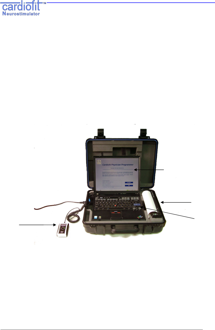
The Physician Programmer uses the programming Wand to transmit a wireless signal in
a format that is required for communication with the stimulator (Figure 1). During
communication, the Wand is placed over the skin next to the stimulator position.
Figure 1 – Model 5300 Physician Programmer
Specifications and user information regarding the wireless technology
The CardioFit system uses a short-range (up to 5 cm) inductive coupling communication scheme
in frequency of 27 kHz. The system is ready to communicate when the green light is blinking on
the programming wand. See warnings and precautions that should be exercised when using the
system under Sections 3 and 4 below.
Screen
Printer
Programming
Wand Keyboards

Unified Physicain Programmer
IFU
RU-53-001 k 8
Contents of package
The model 5300 Physician Programmer consists of:
a. One Laptop PC installed Model 5310 with BioControl CardioFit™ Unified Physician
Programmer software version 2.0;
b. One Programming Wand (Model 5320);
c. One Portable Printer - Model 5330;
d. 1 X Product Literatures
2. INTENDED USE / INDICATION
The model 5300 Physician Programmer is intended for use only with CardioFit™ system,
and is subjected to the same indications for use. In Europe, please refer to RU-05-001.
When using the device under clinical investigation, please refer to the study protocol.
3. PRECAUTIONS
• Do not immerse any part of the Physician Programmer in liquid.
• Physician Programmer (excluding Wand) should be at a distance of at least 1.5
meters from the patient during operation.
• Operator should not touch the PP and patient simultaneously.
• The use of non-BioControl components with BioControl components (other than
supplied and/or approved by BioControl) may result in patient injury, loss of
stimulation or components damage.
• Avoid using the PP and the BioControl stimulator near sensitive electronic equipment.
The low-level wireless signals transmitted by the two devices may interfere with the
electronic equipment.
• Compatibility with other (non-BioControl) implanted devices should be verified prior to
implantation (see section 7)
• This equipment has been tested and found to comply with the limits for a Class A
digital device, pursuant to Part 15 of the FCC rules. These limits are designed to
provide reasonable protection against harmful interference in a residential installation.
• This equipment generates; uses and can radiate radio frequency energy and, if not
installed and used in accordance with the instructions, may cause harmful
interference to radio communications. However, there is no guarantee that
interference will not occur in a particular installation.
Unified Physicain Programmer
IFU
RU-53-001 k 9
4. WARNINGS
• Physician, or other qualified healthcare provider should be trained in using the
programmer. Training programs are available from the manufacturer.
• No modification of this equipment is allowed.
• Do not connect any equipment to Laptop except dedicated Programming Wand, and
formatted USB Memory Stick.
• To avoid the risk of electric shock, this equipment must only be connected to a supply
main with protective earth.
• Pediatric use – safety and effectiveness of Physician Programmer for pediatric use,
has not been established.
• When using the programming wand in a sterile field, place it into a sterile sleeve. The
wand is not and cannot be sterilized.
• Wireless signals from the Physician Programmer may interfere with the performance
of other devices.
• Portable and mobile RF communications equipment can affect the CardioFit.
• Keep cellular phones at least 15 cm away from the device. The cellular phone is a
source of EMI and could affect device’s operation.
• Using the programming wand over a metallic field might decrease its operating range.
CAUTION:
This device complies with Part 15 of the FCC Rules. Operation is subject to
the following two conditions:
(1) This device may not cause harmful interference; and
(2) This device must accept any interference received, including interference
that may cause undesired operation.
FCC WARNINGS:
Modifications not expressly approved by the manufacturer could void the user
authority to operate the equipment under FCC Rules received, including
interference that may cause undesired operation.

Unified Physicain Programmer
IFU
RU-53-001 k 10
5. SETTING UP THE SYSTEM
5.1 Charging the Physician Programmer
1. Charge the PP prior to use and make sure it is fully charged.
5.2 Getting started
1. Verify that the Wand is connected to the programming Wand USB port of the PP.
2. Turn “ON” the PP. The CardioFit Physician Programmer "Welcome" screen will be
automatically uploaded.
Figure 2: Welcome Screen
The green led (ready) of the Wand will light, indicating proper initialization of the
system.
WARNING:
Programming the CardioFit stimulator should be done only in controlled
environments, such an operating room or a clinic
Unified Physicain Programmer
IFU
RU-53-001 k 11
3. Position the programming Wand over the patient's clothes, directly over the
implantable stimulator’s location.
WARNING:
Avoid direct contact with patient skin – place above thin clothing or use a
thin wrapper around the wand to reduce the risk of skin irritation and/or
cross contamination between patients
The blue led (communication) of the wand should blink at a constant frequency of 0.5
Hz (every 2 seconds). Such blinking shows proper communication and readiness for
receiving and transmitting signals.
4. Check the UniPP clock. In case of incorrect time, click “
CHANGE
"
button and adjust the
time using the keyboard.
5.3 General System Interface Description
Select the “I
NTERROGATE
”
(F1)
button on the "Welcome" screen. This initial interrogation
sets up the Physician Programmer screen with the panes and programmable buttons
relevant to the version of the device interrogated.
The Programmer interface consists of 4 tabs, which can be freely navigated by pressing
on the tab name on the left.
General tab: Shows general device settings and allows recording of patient and system
information
Statistics tab: Shows device heart rate statistics and allows for statistics counter reset
Settings tab: Main tab used for programming device stimulation parameters.
Technician tab: Shows device technical parameters
Unified Physicain Programmer
IFU
RU-53-001 k 12
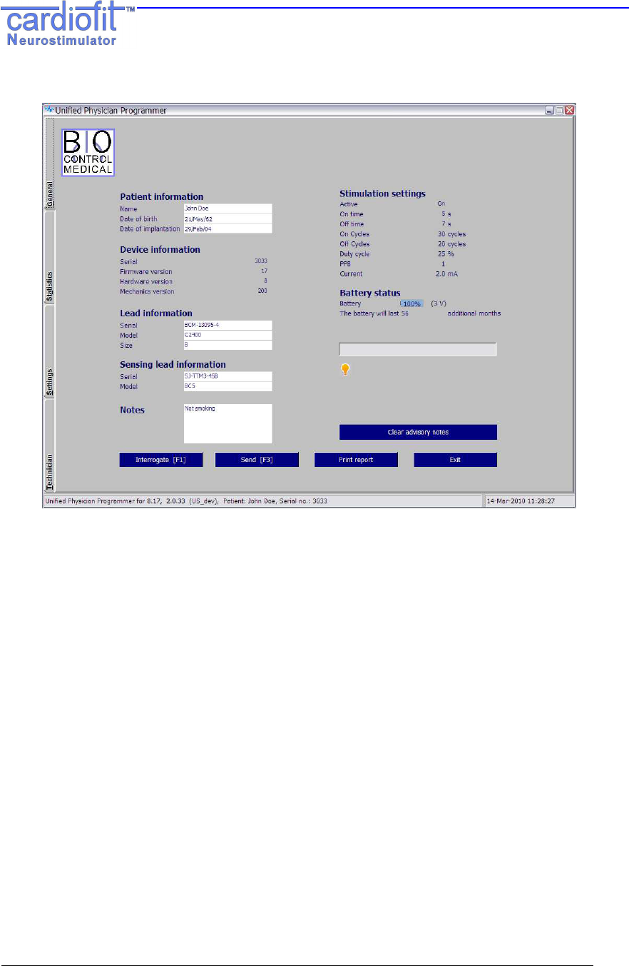
5.3.1 The "General" Tab
Figure 3: The General tab following device Interrogation
The general tab is divided into 3 panes:
The left pane includes patient and system information:
• Patient Information
Patient name – An editable text view. Up to 14 characters
Patient date of birth – An editable date field
Date of implantation – An editable date field
• CardioFit Implantable Stimulator (CIS) information (automatically recognized by the
device)
Serial number - Displays the device’s serial number
Firmware version - Device’s software version
Hardware version - Device’s hardware version
Mechanics version- Device’s mechanical version
• Lead information
Lead serial number - An editable text view up to 32 characters
Lead model - An editable text view up to 32 characters
Lead size - An editable text view up to 32 characters

Unified Physicain Programmer
IFU
RU-53-001 k 13
• Sensing lead information
Serial number - An editable text view up to 32 characters.
Model - An editable text view up to 32 characters.
• Notes
An editable text view which can be used at the physician’s discretion
The right pane includes:
• An overview of current device settings including Activity status: On time, Off time, On
cycles, Off cycles, Duty cycle, PPB, Current
• Battery status and estimated running time.
For a detailed description of these parameters, please see section 5.3.3, The Settings tab.
• Advisory Notes
Advisory notes will appear in case the CIS has experienced one of the following
conditions:
• Battery voltage is too low
• Indication of insufficient discharge of stimulation electrode was given
• Indication from runaway protection mechanism was given
• CardioFit performed reset
• Bad memory shadow indication was given
• Magnet was applied to disable stimulation
• High/low impedance indication was given
.
Actions that should be taken following each advisory note are described in section 9
Pressing the “Clear Advisory Notes” button will clear advisory notes
The bottom pane includes 4 buttons:
Interrogate [F1]
Device Interrogation provides current device settings.
Interrogation checks the parameters of the device and presents the current values of all
programmable buttons and includes last measured RR interval. The interrogate function
does not change parameters stored in the stimulator
Send [F3]
Press this button in order to communicate and apply the parameter setting changes. It
will also perform interrogation and update output parameters such as counters.
Unified Physicain Programmer
IFU
RU-53-001 k 14
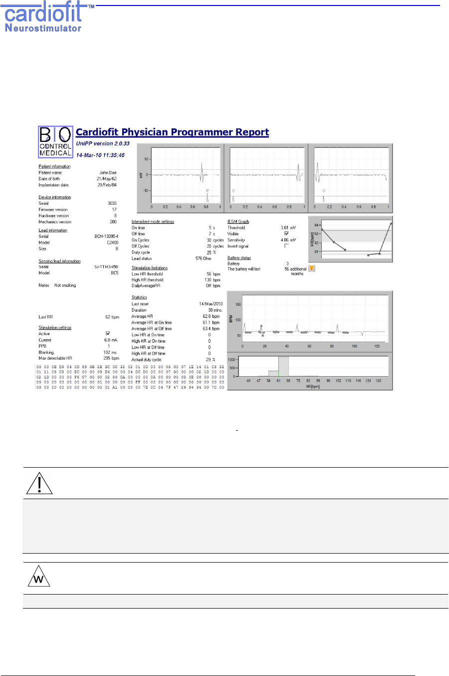
Print Report
This button generates a hardcopy report with device parameters.
After pressing the ‘P
RINT
R
EPORT
’ button, the image file will be ready for printing.
Single click on the Power button will turn on the printer. Double clicks will turn it off.
Figure 4: A Sample Print Report
Exit
Exits the Physician Programmer.
NOTE:
Before exiting the PP and ending the visit with the patient, it is recommended to
save the device logs onto a USB memory stick for further off- line analysis of the
therapy when it is required. Plug the memory stick to the USB port and press
Ctrl+Alt+L button on the UniPP Keyboard
WARNING:
Format the USB memory stick prior to use with the Physician Programmer
These 4 buttons (Interrogate [F1], Send [F3], Print Report, and Exit) appear also in the
setting tab and have similar functions.
Unified Physicain Programmer
IFU
RU-53-001 k 15
5.3.2 The "Statistic" tab; Therapy evaluation.
The UniPP calculates and analyses the effect of the stimulation parameters on the
patient's heart, thus enabling evaluation of optimal therapy setting. Measures are
presented numerically and graphically. Statistics are accumulated by the CIS. The
statistics can be reset manually.
The "Statistic" tab information is typically used at the beginning of the patient visit, in
order to estimate the effect of the last prescribed therapy.
At the end of the visit, the "Statistic" tab should be revisited in order to reset the data and
enable estimation of therapy effect at the next visit.
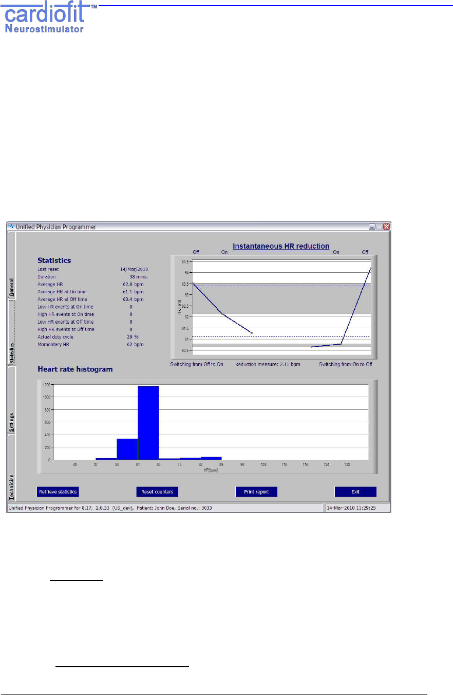
Figure 5: The Statistic tab
The Statistics tab is divided into 3 panes:
The left Statistics pane includes the Heart Rate (HR) numerical information:
• Last reset – Date of the last statistical information reset
• Duration – Time period over which the statistics are calculated and presented
• Average HR – The average HR of all heart beats detected by the device
• Average HR at On time - The average HR of the heart beats detected within the pre-
specified HR detection thresholds (low and high HR) and calculated by the device
while stimulation was delivered
Unified Physicain Programmer
IFU
RU-53-001 k 16
• Average HR at Off time - The average HR of the heart beats detected within the pre-
specified detection limits (low and high HRs) and calculated by the device while
stimulation was not given
• Low HR events at On time - A counter registering how many detection events (R
waves) occurred at a rate below that defined as Low HR Threshold.
• High HR events at On time - A counter registering how many detection events (R
waves) occurred at a rate above that defined as High HR Threshold.
• Low HR events at Off time - A counter registering how many detection events (R
waves) occurred at a rate below that defined as Low HR Threshold.
• High HR events at Off time - A counter registering how many detection events (R
waves) occurred at a rate above that defined as High HR Threshold.
• Actual Duty cycle – The ratio (in percentage) between the period at which
stimulation was administrated and the period at which stimulation was not
administrated.
• Momentary HR – The value of the last RR interval measured by the device in bpm
The right HR Reduction pane includes graphical presentation of the average
instantaneous heart rate reduction (iHRR) for the time duration indicated in the left pane.
The graph provides visual evaluation of the effect of stimulation on the heart rate. The
three left points are the average HR for the last 2 beats before the stimulation is switched
from off to on and the average HR for the first beat after switching from off to on
respectively. The three right points are the average HR for the 2 last beats before the
stimulation is switched from on to off and the average HR for the first beat after switching
from on to off respectively. The heart rates shown are averaged over all on/off cycles
that occurred since the last reset.
The iHRR value is presented below the figure. It is calculated from the mean value of the
first two points (off stimulation) minus the mean of the following two points (on
stimulation).
Two blue dashed lines are drawn at the values of the
average HR at On time and
average HR at Off time.
Zooming in/out
Marking the desired area in the graph to be zoomed-in while left clicking the “mouse”
will provide focused area of interest. Repeat the procedure for higher magnification if
required.
Right click will reset the axis scale.
NOTE:
The iHRR figure statistic is reliable only if the interval duration (since last
reset counters) is greater than 24 hours
The bottom Heart rate histogram pane shows a graphical presentation of the heart rate
histogram for the time duration indicated in the left pane and the functional button.
Unified Physicain Programmer
IFU
RU-53-001 k 17
Retrieve statistics
Updates the statistics parameters including update of the HR reduction figure as well
as the HR histogram,
Click the 'P
RINT
R
EPORT
' button after pressing the 'R
ETRIEVE STATISTICS
' button for
patient history records. This report documents the therapy performance since last
visit (since last reset counters activation).
Reset counters
Resetting the CardioFit statistics counters. After pressing the button, a message box
appears and indicates successful reset action.
Click the 'P
RINT
R
EPORT
' button after pressing the 'R
ESET
C
OUNTERS
'
button for
patient history records. This report documents the end of visit therapy parameter
setting.
NOTE:
Pressing “Reset counters” button will not update the screen with reset
counters; for the updated numbers please use “retrieve statistics”.
Unified Physicain Programmer
IFU
RU-53-001 k 18
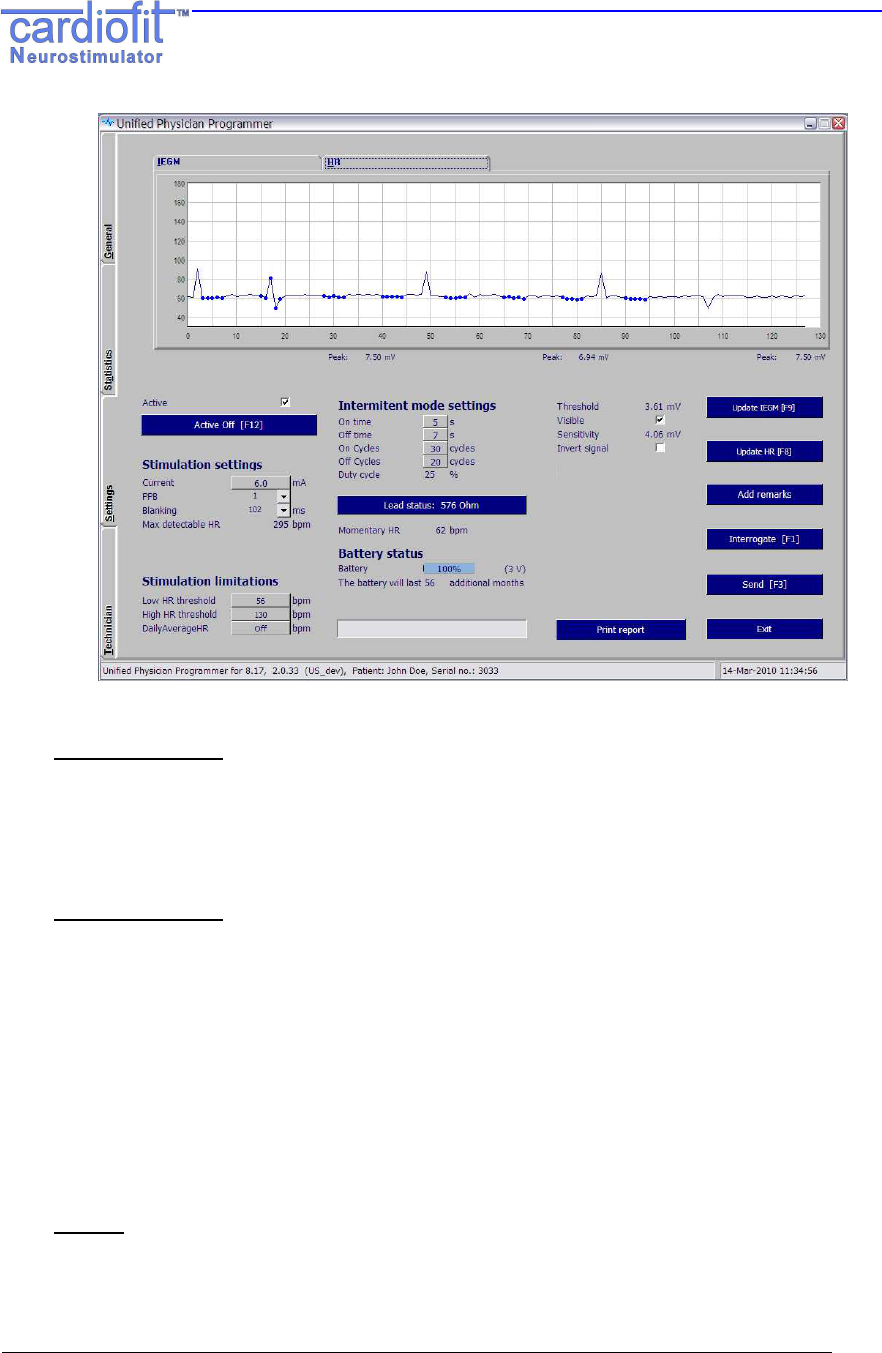
5.3.3 The "Setting" Tab
This screen allows the operator to control the stimulation therapy delivered by the device
to the patient. Adjustment of HR detection and Vagus nerve stimulation therapy
programming and changes are performed through the Setting tab.
The top pane contains a switch screen of IEGM and HR streaming. Clicking the relevant
tab on the top of the screen switches between the screens. Description of buttons and
panes below the switch screen is found under the HR screen.
IEGM screen
The CardioFit detects right ventricle signal in order to synchronize stimulation with
the cardiac cycle. The max detection sensitivity = 2mV.
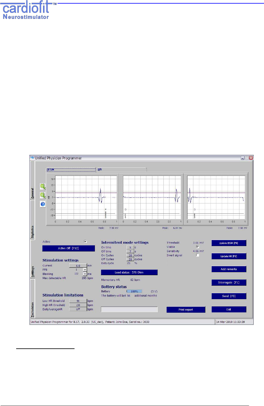
Figure 6: The IEGM Setting tab
Update IEGM (F9)
The Update IEGM (F9) button is located at the right pane of the setting screen
Pressing the button will update the three windows that compose the IEGM screen.
Each window represents one second.
Please note: the three windows are not continuous in time.

Unified Physicain Programmer
IFU
RU-53-001 k 19
Zooming in/out
The zoom control buttons are located at the left side of the IEGM screen marked by
+ and –.
Pressing the + results in IEGM magnifying, each pressing will provide higher
magnification, allow better view of the IEGM and ease threshold setting.
Pressing the – button will decrease the IEGM magnification.
Stimulation annotation line
Appears as a black line below the IEGM and the threshold graph,
When stimulation is being delivered an upward pointing bar will be presented, when
stimulation is being inhibited a downward pointing bar will be presented, in addition,
a letter representing the inhibition cause will appear below the bar as follow:
Inhibition letter legends: (also available when pressing the "?" button)
O – Off time, Off cycle
M – Magnet has been applied.
F – Fault (lead status out of range, low battery, bad shadow, device reset)
R – Runaway protection has been activated.
D – Discharge, in case the electrode has not been sufficiently discharged.
H – High HR, short RR.
L – Low HR, Low daily Avg. HR
I – Impedance not measured
P – Pulse
S - Sense
IEGM max measured amplitude
Below each IEGM window screen, the “Peak” R wave value is presented.
Detection Threshold
The threshold for R wave detection appears on the grid of the display as a bright
purple/magenta line that can be set higher or lower by left clicking and dragging or
by entering the numeric value.
An optimal threshold setting should be at two-thirds of the R wave peak.
If the “visible” box is not checked, the threshold will not be shown.
The "Sensitivity" indicator shows the guaranteed sensitivity at the chosen detection
threshold
Invert signal
Marking the check box will invert the heart signal; use this button when the negative
projection of the signal is much greater then the positive.
HR screen
The HR screen presents the heart rate in bpm during the last 128 RR intervals with
marks for stimulations. The figure enables on-line evaluation of the heart rate
response to stimulation.
Unified Physicain Programmer
IFU
RU-53-001 k 20
Figure 7: The HR Setting tab
Update HR [F8]
This button is located at the right pane of the setting screen
Pressing this button will display a graph of heart rate of the last 128 RR intervals.
Every such heartbeat is marked by a green dot on the graph. Stimulated R waves
will be marked in larger dots.
Zooming in/out
Marking the desired area in the graph to be zoomed-in while left clicking the “mouse”
will provide focused area of interest. Repeat the procedure for higher magnification if
required.
Right click will reset the axis scale.
The bottom pane of the “Setting” tab includes stimulation parameters settings:
Stimulation Settings:
Active
Check box may be un-checked in order to inactivate the device. In the ‘non active’
mode the CIS is not sensing or counting and not stimulating. When the box is
checked the CIS is activated.
Unified Physicain Programmer
IFU
RU-53-001 k 21
Current
Sets the amplitude of the current provided by the stimulation lead in milliamps (mA).
Value can only be selected from a table appearing when button is left-clicked, as a
safety measure. Current should not be increased by more than 0.2mA at one time.
The default value is 0mA, max value is 6mA.
PPB
Pulses Per Beat will set a constant number of pulses per single heartbeat.
Max PPB value is 3 in regular use and 8 in implantations (only appear in the
CardioFit-X version).
The following table specifies stimulation interval duration from at each specified PPB
PPB actual PPB Delay From R
[ms] Pulse Repetition
Interval [ms]
1 1 94 8
2 2 8 86
3 3 8 39
Blanking
Determines the duration of blanking period following stimulation. The purpose of
blanking during which there is no detection, is to prevent T wave detection, as well
as to prevent the stimulation itself from causing misdetection. Range: 8 ~ 1000 ms in
7-8ms steps. It appears in the IEGM as uncolored line area.
The default value is 102ms.
Max detectable heart rate
The number appearing is the maximum regular beats, or more precisely -
Intracardiac signals, per minute that may be detected. This value is the product of
several variables, including: PPB, and blanking. The ‘Max detectable HR’ field
becomes red if the programmed ‘High HR Threshold’ is greater than 90% of the max
detection rate.
WARNING:
If the High HR Threshold is higher than the Max detectable HR,
the device may not be able to prevent stimulation when it is resulted from
detection of noisy signal

Unified Physicain Programmer
IFU
RU-53-001 k 22
Stimulation Limits:
High HR Threshold
The heart rate above which no stimulation is provided no matter what the mode,
cycle or stimulation parameters are. Stimulations are inhibited when 3 out of 4 of the
last RR intervals are shorter than this value. The default value is 130 BPM.
Low HR Threshold
The heart rate below which no stimulation is provided no matter what the mode,
cycle or stimulation parameters are. Stimulations are inhibited when 3 out of 4 of the
last RR intervals are longer than this value. The default value is 56 BPM.
Daily Average RR
This feature cancels the stimulation Cycle mode. It automatically use the calculated
last 24 hours average heart rate by the device and enable stimulation only when the
measured heart rate is higher than the average value. The value is updated
automatically every 24 hours.
At the first time used, the value should be set manually.
When the default ‘Off’ value is presented the stimulation limitation ignores this
feature.
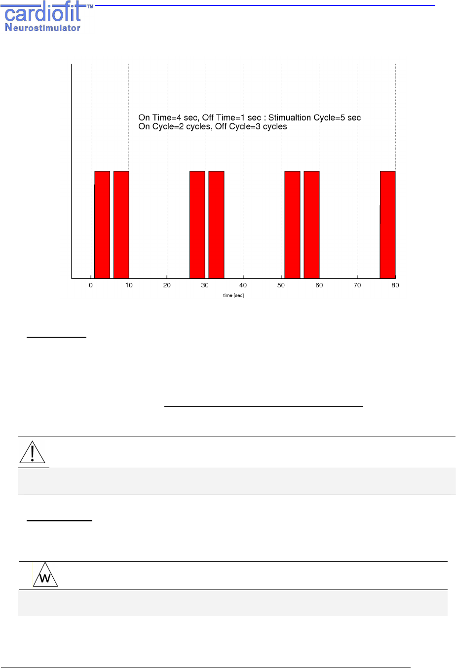
Intermittent Mode Settings:
Treatment mode
The CardioFit™ stimulation algorithm consists of four combined time intervals, the
On/Off Time and the On/Off Cycles.
CardioFit administers stimulation in an intermittent, periodic manner. The period is
determined by the "on time" and "off time" programmable parameters.
A "stimulation cycle" is the time period consisting of a single "off" period followed by
a single "on" period.
The "On cycle" and "Off cycles" programmable parameters give further control of
the intermittent administration of stimulation by allowing a long period in which no
stimulation is administered. CardioFit will administer "On cycle” normal stimulation
cycles, to be followed by a period of "Off cycles" stimulation cycles in which no
stimulations will be administered.
For example: See Figure 8, where the following parameters are programmed:
on time=4 sec, off time=1 sec, on cycle=2, off cycle=3.
Based on these parameters, the stimulation cycle=off time + on time = 5 sec.
Therefore, 10 seconds (2 cycles) of intermittent stimulation are followed by 15
seconds of no stimulations, etc.
Unified Physicain Programmer
IFU
RU-53-001 k 23
Figure 8: On/Off time and On/Off Cycle operation parameters.
Duty Cycle
The duty cycle indicator calculates and present the actual activation time according
to the last programmed settings. The indicator becomes red if the calculated value
exceeds 30%. The duty cycle should not exceed 30%.
)()( OffCycleOnCycleOffTimeOnTime
OnCycleOnTime
DutyCycle +⋅+
⋅
=
NOTE:
Values for the treatment mode parameters can only be chosen from a table
appearing when button is left-clicked, as a safety measure
Lead Status
Calculates the CSL lead impedance and provide an indication status in 20%
accuracy. Working range is 300 – 2500 Ω, 4 – 10µF.
WARNING:
Lead status ‘Short’ or ‘High’ may indicate on lead break or damaged
insulation and need to be reported immediately to BioControl representative
Unified Physicain Programmer
IFU
RU-53-001 k 24
The result will be displayed on the Lead status button and will be written in the log
files as a comment.
To perform the test press the ‘lead status’, the test take a minute and is part of a
routine On Time cycle, a progress bar indicate on the test status.
In order to perform the test, four conditions must be fulfilled. The conditions are:
On time ≥ 1
On cycle ≥ 1
Active On
R wave detection
NOTE:
If one of the conditions is not fulfilled the Programmer will issue a warning:
"Impedance measurement was not performed. Verify that stimulation is not
inhibited". The lead status shown will be from the last successful test.
Stimulation will not be delivered if the lead status results is not “OK”
Battery Status
Battery capacity indicator is shown as a blue strip containing a percentage measure
of full capacity, Battery Voltage is provided in Volt units in parenthesis.
Battery expected remaining time is expressed in months.
NOTE:
If less than 3 months remain for battery operation (assuming no change
in setting) a message will appear in the gray space below
“Please schedule device replacement”.
Unified Physicain Programmer
IFU
RU-53-001 k 25
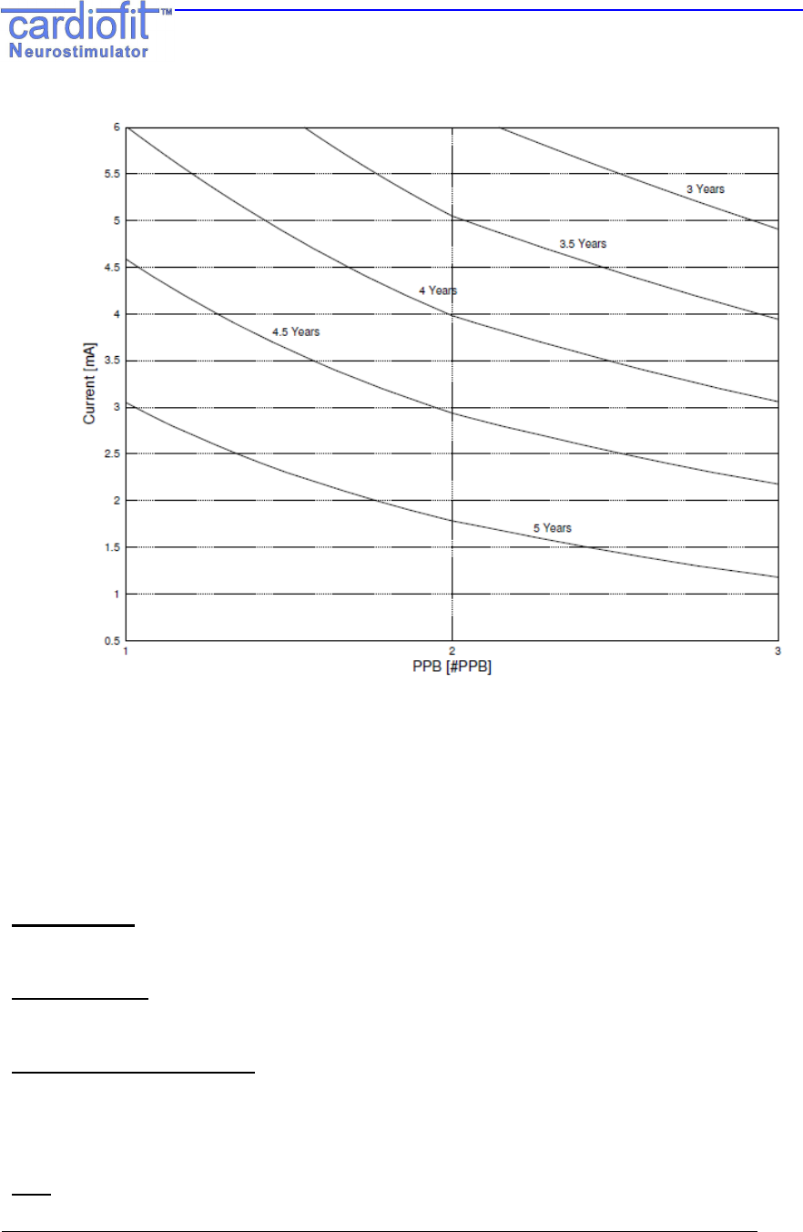
Figure 9: Predicted device life time as function of current and PPT
The nominal predicted lifetime of the CardioFit™ Implantable Stimulator battery in
the maximal therapeutic setting is 4.5 years and the minimum is 3.0 years.
The nominal predicted lifetime is calculated under the following conditions:
Stimulation electrode Impedance: 1740Ω; Capacitance: 4.7µF
Stimulation current: 5mA, 3 pulses per beat,
Average HR: 100bpm, Stimulation duty cycle: 25%.
Print Report
See section 5.3.1
Add Remarks
Adds a line in the log file, on which user remarks may be written.
Emergency button [F12]
This button function is to switch the device to an active off mode without the need of
pressing the "send" button, use this button when there is need to terminate the device
function immediately.
Exit
Exits the Physician Programmer and returns to Windows.
Unified Physicain Programmer
IFU
RU-53-001 k 26
NOTE:
When a button is pressed or a new parameter is typed a light blue
box will appear around it, until the button “Send” [F3] has been
pressed. It is possible to program several parameters one after the
other and then press the “Send’ button.
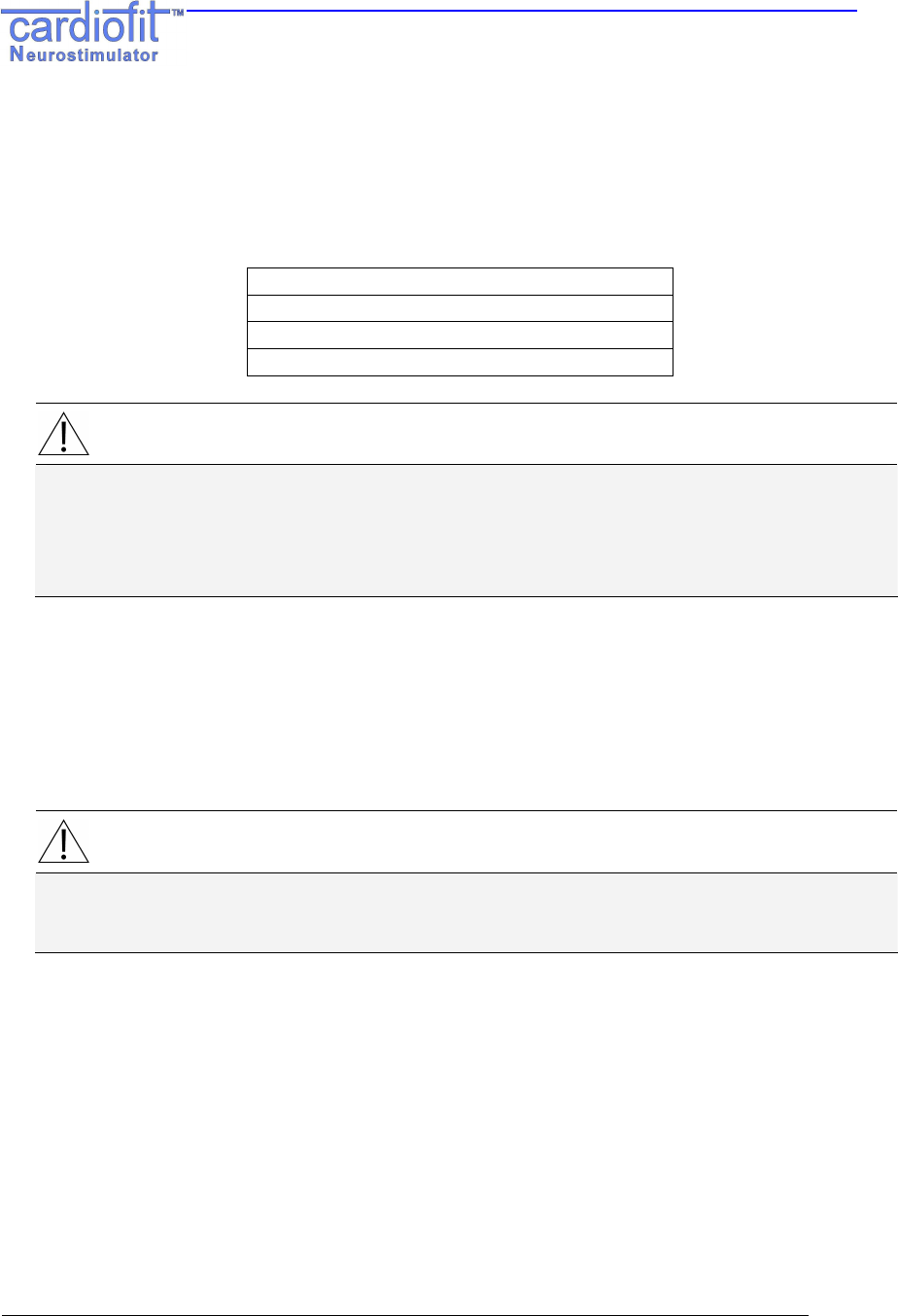
Range and default of programmed parameters list:
Parameter Range Default
On Time [s] 0…(1)…10…(5)…255 0
Off Time [s] 0…(1)…10…(5)…255 0
PPB 1, 2, 3 1
Current [mA] 0…(0.1)…6 0
On Cycles 0…(1)…127 1
Off Cycles 0…(1)…127 0
Low Stimulation Limit [BPM] 30…(4)…320 56
High Stimulation Limit [BPM] Off, 30…(4)…320 150
Daily Average HR Off, 30.1 - 7680 0ff
Blanking [ms] 8…(8)…1000 102
Detection Threshold [mV] 1.88 to 39.69 39.69
Detection Thresholds
sensitivity [mV] ≥2 39.69
6. THERAPY SETTING AND OPTIMIZATION PROGRAM
WARNING:
The Physician Programmer should be used only by authorized and
trained personal
NOTE:
Make sure the programming wand is correctly positioned over the
stimulator, and a green light+ blue blinking light appears. Hold the
programming wand in place until the transmitted parameters had
been programmed.
Unified Physicain Programmer
IFU
RU-53-001 k 27
NOTE:
After each time a button is pressed or a parameter is typed the
“send” button on the screen should be pressed, or alternatively
press the keyboard “F3” button.
6.1 General
This section provides guidance and recommendation regarding use of the CardioFit
Unified Physician Programmer (UniPP) for device activation and parameter setting
optimization in patients implanted with the CardioFit™ System during the adjustment
period that all implanted subjects undergo in order to provide them with optimal
CardioFit therapy. This period is defined as "optimization period". The optimization
period starts at weeks 3-4 post operative (depending on patient recovery from system
implantation and wound healing), and lasts around 4 to 6 weeks. In order to optimally
set the therapy, approximately 6 to 8 setting sessions are required during that period
depends on patient adjustment and tolerability to the stimulation.
6.2 Therapy Optimization Goal
The goal of the optimization is to adjust. the stimulation parameters to the patient specific
physiological characteristics in order to achieve the optimal synchronized vagus nerve
stimulation (with the depolarization rate of the ventricles), CardioFit therapy settings.
Optimal setting criteria are:
• Instantaneous Heart Rate Reduction ("iHRR") greater than 0.5 bpm in an
interval ≥ 24-hour; and
• Minimal discomfort to the patient
6.3 Communication rules with the patient
• Prior to each session consult with the patient’s physician regarding his or
her condition. Physical examination is required prior to each optimization
session.
• Ask the patient for his/her condition - presence of adverse events or
unusual feelings since last visit and during the visit should be noted.
• It is recommended to use standard stimulation sensation scale to
standardize patient comfort with the programmed therapy setting level.
6.4 Visit Activities Flow
• Physical examination should be performed prior to parameter change.
• Review the last patient clinical outcome
o Stimulation discomfort characteristic - Interview patient for his
response to therapy and general clinical feeling. Ask patient
to determine the stimulation discomfort level since last visit, if
any, using the stimulation sensation pain scale
o Adverse events
Unified Physicain Programmer
IFU
RU-53-001 k 28
o Electrocardiogram from most updated 12-lead ECG/Holter.
Identify any new significant abnormalities (Heart rate,
conduction, arrhythmias, etc.)
• Interrogate the device and review the information appeared in the
"General" tab of the UniPP. Identify any parameter settings discrepancy or
system malfunctions.
• Switch to the "Statistic" tab and press the "retrieve statistic" button. Review
the last interval heart rate outcome and compare it with the previous
results.
• Set therapy parameters
• After the last parameter setting change, follow the patient for any
discomfort for at least 30 minutes before release.
6.5 Parameter setting process
• Use the "Setting" tab in the UniPP for setting parameters
• Verify that "active" button is marked
• HR wave detection:
Press the IEGM tab to view IEGM and than press the "Update IEGM" [F9]. Verify
correct signal threshold for detection.
Detection thresholds should be set to the 2/3 amplitude of R wave. Minimum
sensitivity is 2 mV.
• At the first activation of the device set the parameters as indicated in
following table.
Parameter Value
On Time [s] 10
Off Time [s] 15
PPB 1
Current [mA] 0.1
On Cycles 30
Off Cycles 20
Low Stimulation Limit [BPM] 56
High Stimulation Limit [BPM] 130
Daily Average HR Off
Blanking [ms] 70
• Increase current in steps of 0.2 mA and press "Send [F3]" button. Allow
patient to adjust the change for 5 minutes.
• When the patient detects stimulation, ask him/her to determine the
stimulation sensation level. If the sensation is intolerable, wait for at least
15 minutes before proceeding. In case that sensation level does not
decrease, reduce current in 0.1 mA steps until comfortable sensation of
stimulation is achieved. Set the final parameters for the optimization
session accordingly.
Unified Physicain Programmer
IFU
RU-53-001 k 29
• Continue with the same procedure at each optimization session up to 5.5
mA and continuously evaluate the effect of the stimulation setting on iHRR.
6.6 Instantaneous HRR evaluation and PPB/ON time change
iHRR can be observed at the "Statistics" tab: HR statistics, HR reduction figure and HR
distribution histogram for the last interval and in the "Setting" tab: HR figure.
• ON Time settings change:
o Review the HR reduction figure appears in the "Statistic" tab
after pressing the "Retrieve" button at the beginning of each
session.
o Increase ON time, if the HR value at the last measuring point
of the Stimulation ON time is lower or equal to the HR value
of the previous measuring point and the average HR.
o Decrease ON time, if the HR value at the last measuring point
of the Stimulation ON time is higher than the HR value of the
previous measuring point and the average HR.
o Please note that whenever On time is modified, the Off time
should be modified accordingly in order to keep the overall
Duty Cycle constant.
• PPB setting change;
When significant iHRR in an interval ≥ 24-hours is observed switch setting to 2
PPB.
o The change may require reduction of 0.5mA in pulse current
o Re-evaluate the iHRR in the following visit. In case the
measured iHRR value decreased following the change, revert
to the last setting with the 1 PPB.
• It is mandatory to print report at the beginning and completion of visit, all
reports should be reviewed and signed by the patient physician.
NOTE:
Press the E
XIT
key after parameter setting is completed
Unified Physicain Programmer
IFU
RU-53-001 k 30
7. INTERACTIONS WITH CARDIAC IMPLANTABLE DEVICES
7.1 Implanting CardioFit with another cardiac implanted device in the
same patient
This section provides the procedure that is to be followed when implanting CardioFit in a
patient with an implanted cardiac device (e.g. pacemaker, bi-ventricular pacemaker
and/or defibrillator) under the approved use of the CardioFit within the specific
geography. Following this procedure shall minimize the risk of interaction between the
two implanted devices and will allow safe delivery of therapy from both of them.
Before implantation:
• Before implanting one or both of the devices, ensure that both devices can
communicate with their respective programmers:
o Place both devices at the same distance at which they will be implanted in the
patient:
Do not remove the devices out of their sterile packages
If one of the devices is already implanted, place the other device (still
inside the sterile package) on the patient on the area where it is to be
implanted
Initiate communication with both devices and ensure communication is
error free
If one device’s programming wand interferes with the other devices
programming wand, repeat the test with only one programming wand in
the device area – both devices should be able to communicate with their
programmer while the other programmer is not near
• If both devices can communicate proceed with implantation
7.2 Programming device parameters
After both devices are implanted, use the following guidelines to set pacing/sensing
parameters in the devices. These guidelines minimize the possibility of CardioFit and the
other device sensing each other’s stimulations as cardiac events.
Note: It is possible and common for a device to be both anti-bradycardia and anti-
tachycardia (e.g. a CRT/D). In this case guidelines for both types of modes should be
followed
NOTE:
Please note that the term ‘ICD’ refers to: Single chamber Implantable
Cardioverter-Defibrillators, Dual chamber Implantable Cardioverter-Defibrillators
and Cardiac Resynchronization Therapy- Implantable Cardioverter-Defibrillators
(CRT-D)
Unified Physicain Programmer
IFU
RU-53-001 k 31
For several parameters below, conversion from beats per minute (bpm) to milliseconds
(ms) is needed. Use the following formula:
ms = 1000*60/bpm
bpm = 1000*60/ms
• Never use uni-polar sensing in a device implanted with CardioFit
• Set the CardioFit sensing threshold to be at least 50% of the R-wave amplitude
• Ensure that the other device has a refractory period of at least 135 ms following a
sensed ventricular event
o The 135 ms minimal refractory period should be set in all leads used for
sensing by the other device. For devices that sense both in the atrium and
ventricle, both the atrial refractory period after ventricular sensing (e.g. Post-
Ventricular Atrial Blanking) and the ventricular refractory period after
ventricular sensing should be greater than 135 ms
• If the other device is an anti-bradycardia device:
o CardioFit Low HR threshold shall be set to be above the other device’s basic
pacing rate
CAUTION:
In case that CardioFit low HR threshold is set below the other device’s basic
pacing rate, the CardioFit will stimulate on paced beats. The physician should
take this into account when programming CardioFit stimulation parameters, or
should consider abolition of CardioFit implantation
o Other device is using bi-ventricular pacing
The other device’s and CardioFit’s parameters shall be set to values such
that the other device’s V-V delay is smaller than the CardioFit maximal
detectable heart rate
Example:
Other device’s V-V delay = 50 ms
130 ms = 1200 bpm
CardioFit Maximal detectable heart rate should be smaller than 1200 bpm
• If the other device is an anti-tachycardia device
o The other device’s and CardioFit’s parameters shall be set to values such that
the CardioFit High HR threshold is well below the other device’s VT zone
Example:
Other device’s VT zone = 180 bpm
CardioFit High HR threshold should be below 160 bpm
o The other device’s and CardioFit’s parameters shall be set to values such that
the CardioFit High HR threshold is well below the other device’s anti-tachycardia
pacing interval
Unified Physicain Programmer
IFU
RU-53-001 k 32
Example:
Other device’s anti-tachycardia pacing interval= 200 ms
200 ms = 300 bpm
CardioFit High HR threshold should be below 280 bpm
7.3 Patient follow-up
During patient follow-up special attention should be paid to ensure that the above
guidelines are still in effect.
Also, any irregular events should be scrutinized to ensure that they did not occur due to
device-device interactions. Such events may include:
• Defibrillation shocks
• Pacemaker detection problems (double-counting)
• CardioFit detection problems
• Communication problems
It is recommended that any record of the IEGM from such an event be inspected to
ensure that no device-device interaction had occurred.
NOTE:
Both devices, ICD and the CardioFit cannot be interrogated simultaneously
WARNING:
It is advised to ensure proper sensing by the CardioFit of intrinsic and
paced beats
8 MAINTANANCE, HANDLING, AND STORAGE
8.1 Maintenance
Except for PP battery charging and cleaning of the Programming Wand the Physician
Programmer does not require maintenance:
• Do not sterilize the programming wand, use only disinfecting pre-moistened cloth and
wipe the Wand surface.
• Return the UniPP to BioControl if repair or replacement is required.
• If required, the Physician Programmer components can be cleaned with a moistened
cloth.
NOTE:
For additional PC laptop and printer operation and maintenance instructions
please refer to the vendors manuals included in this package

Unified Physicain Programmer
IFU
RU-53-001 k 33
8.2 Handling
• Never immerse the programming wand in liquid.
• Place thermal A4 paper in printer
.
8.3 Storage
• Do not store the Physician Programmer where it might be exposed to water or other
liquids. Moisture can damage its functionality!
• Store the Physician Programmer between 0ºC and 45ºC. Temperature outside this
range can damage the Physician Programmer.
• Relative Humidity (RH): Between 10% and 95% RH.
• Atmospheric Pressure: Between –400m and 3000m (700-1060 hPa).
• Store the Physician Programmer in a secure place.
Unified Physicain Programmer
IFU
RU-53-001 k 34
9. TROUBLESHOOTING
The following table presents possible errors and suggested solutions:
Error Feature Suggestion
Blue light
not blinking
Check the green light – if the green light is off take
the following actions:
1. Start the Physician programmer.
2. Verify that the Physician Programmer and
programming wand are properly
connected.
3. disconnect the programmer from mains
If the green light is on take the following actions:
1. Reposition wand
2. Ask patient to change his/her position.
3. Check physician programmer operation on
a neutral CardioFit™-X device.
4. Change the programming wand.
5. change location together with the patient
6. In case the problem did not resolved
contact BioControl Medical (BCM) Ltd.
Communication error
Blue light
blinking in
high
frequency
1. Check if the CardioFit programming wand is
located in the proximity of another
programming wand (ICD, CRT).
2. Try to isolate the CardioFit programming wand
from others electrical devices
3. Contact BioControl Medical (BCM) Ltd.
Physician Programmer not
responding or a persistent
malfunction not related to
communication.
1. Restart the program.
2. If the problem is not resolved, restart the
system.
3. Contact BioControl Medical (BCM) Ltd.
CAUTION:
In case of unsuccessful Turn-off of the neurostimulator while using the Physician
Programmer, use safety magnet to turn the neurostimulator OFF. Please contact
BioControl Medical personnel, immediately.

Unified Physicain Programmer
IFU
RU-53-001 k 35
The following table presents possible error messages:
Message Description Action
"A different CardioFit was
interrogated, do you wish
to proceed?"
After interrogation,
the serial number of the
device is different from
the last SN.
Press YES in case the new device
(patient) interrogation was scheduled or
press NO and interrogate again the right
device in the case of a mistake.
"There is no
communication" Indicates a
communication error. See the table above.
"Unfamiliar device or old
device version or
communication error"
Unexpected model or
version was read, may
indicate an old device
version.
Re-interrogates th
e device, if the massage
still appears contact BioControl Medical.
"Unable to write to a log
file" In case of an error in
writing to a log file. Make sure all log files are closed.
"Unable to read from the
log file" A problem in reading
the log file. Make sure all log files are closed.
“Disk on key is not
connected, operation
canceled! “
Disk on key should be
connected in order to
perform this action.
Connect a Disk-On-Key to the
programmer.
"The operation cannot be
performed when device is
not active"
The desired action
requires an active
CardioFit.
Appears when updating IEGM or HR while
the device is set to “active off”, set the
device to “Active on”.
"Please schedule device
replacement"
When CardioFit
longevity is less than 3
months. Schedule device replacement.

Unified Physicain Programmer
IFU
RU-53-001 k 36
10.
PRODUCT INFORMATION AND SUPPORT
For technical support for the CardioFit™ system Physician Programmer or any of its
accessories, please contact BioControl:
BioControl Medical (B.C.M) Ltd.
3 Geron St.
Yehud, 56100
ISRAEL
TEL: + 972-3-6322126
FAX: +972-3-6322125
Email: info@biocontrol.co.il
11.
DISCLAIMER OF WARRANTY
Although the Physician Programmer hereafter referred to as “Product” has been carefully
designed, manufactured and tested prior to use, the Product may fail to perform its
intended function satisfactorily for a variety of reasons. Warnings contained in the
Product labeling provide more detailed information and are considered an integral part of
this disclaimer. BioControl, therefore, disclaims all warranties, both expressed and
implied, with respect to the Product. BioControl shall not be liable for any incidental or
consequential damages caused by any use, defect or failure of the Product, whether the
claim is based on warranty, contract, tort or otherwise.
The exclusions and limitations set out above are not intended to, and should not be
construed so as to, contravene mandatory provisions of applicable law. If any part or
term of this disclaimer of warranty is held by any court of competent jurisdiction to be
illegal, unenforceable or in conflict with applicable law, the validity of the remaining
portion of the disclaimer of warranty shall not be affected and all rights and obligations
shall be construed and enforced as if this disclaimer of warranty did not contain the
particular part or term held to be invalid.
Unified Physicain Programmer
IFU
RU-53-001 k 37
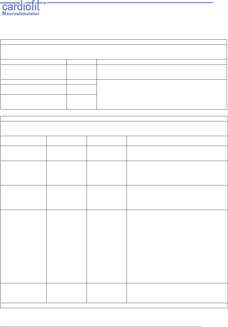
Appendix A. Electromagnetic environment – guidance IEC 60601-1-2
Guidance and manufacturer’s declaration – electromagnetic emissions
The Physician Programmer model 5300 & CardioFit-X Ver 8.17 are intended for use in the electromagnetic
environment specified below. The customer or the user of the Physician Programmer model 5300 & CardioFit-X ver
8.17 should assure that it is used in such an environment.
Emissions test Compliance Electromagnetic environment - guidance
RF emissions CISPR 11 Group 2 The Physician Programmer model 5300 & CardioFit-X ver 8.17
must emit electromagnetic energy in order to perform their
intended function. Nearby electronic equipment may be affected.
RF emissions CISPR 11 Class B
Harmonic emissions
IEC 61000-3-2 Class D
Voltage fluctuations/flicker
emissions
IEC 61000-3-3
Complies
The Physician Programmer model 5300 & CardioFit-X ver 8.17 are
suitable for use in all establishments, including domestic
establishments and those directly connected to the public low-
voltage power supply network that supplies buildings used for
domestic purposes.9
Guidance and manufacturer’s declaration – electromagnetic immunity
The Physician Programmer model 5300 & CardioFit-X Ver 8.17 are intended for use in the electromagnetic
environment specified below. The customer or the user of the Physician Programmer model 5300 & CardioFit-X Ver
8.17 should assure that it is used in such an environment.
Immunity Test IEC 60601
test level Compliance level Electromagnetic environment – guidance
Electrostatic
discharge (ESD)
IEC 61000-4-2
±6 kV contact
±8 kV air
±6 kV contact
±8 kV air
Floors should be wood, concrete or ceramic tile. If
floors are covered with synthetic material, the
relative humidity should be at least 30 %.
Electrical fast
transient/burst
IEC 61000-4-4.
±2 kV for power
supply lines
±1 kV for
input/output lines
±2 kV for power
supply lines
±1 kV for
input/output lines
Mains power quality should be that of a typical
commercial or hospital environment
Surge
IEC 61000-4-5
±1 kV differential
mode
±2 kV common
mode
±1 kV differential
mode
±2 kV common
mode
Mains power quality should be that of a typical
commercial or hospital environment.
Voltage dips, short
interruptions and
voltage variations on
power supply input
lines
IEC 61000-4-11.
<5 % U
T
(>95 % dip in U
T
)
for 0,5 cycle
40 % U
T
(60 % dip in U
T
)
for 5 cycles
70 % U
T
(30 % dip in U
T
)
for 25 cycles
<5 % U
T
(>95 % dip in U
T
)
for 5 sec
<5 % U
T
(>95 % dip in U
T
)
for 0,5 cycle
40 % U
T
(60 % dip in U
T
)
for 5 cycles
70 % U
T
(30 % dip in U
T
)
for 25 cycles
<5 % U
T
(>95 % dip in U
T
)
for 5 sec
Mains power quality should be that of a typical
commercial or hospital environment. If the user of
the Physician Programmer model 5300 &
CardioFit-X Ver 8.17 requires continued operation
during power mains interruptions, it is
recommended that the Physician Programmer
model 5300 & CardioFit-X Ver 8.17 be powered
from an uninterruptible power supply or a battery
Power frequency
(50/60 Hz) magnetic
field
IEC 61000-4-8
3 A/m 3 A/m Power frequency magnetic fields should be at
levels characteristic of a typical location in a typical
commercial or hospital environment.
NOTE U
T
is the a.c. mains voltage prior to application of the test level.
Unified Physicain Programmer
IFU
RU-53-001 k 38
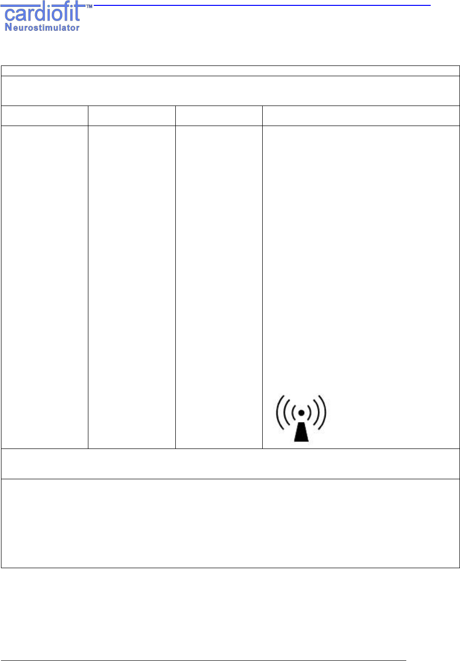
Guidance and manufacturer’s declaration – electromagnetic immunity
The Physician Programmer model 5300 & CardioFit-X Ver 8.17 are intended for use in the electromagnetic
environment specified below. The customer or the user of the Physician Programmer model 5300 & CardioFit-X Ver
8.17 should assure that it is used in such an environment.
Immunity Test IEC 60601 test
level Compliance level Electromagnetic environment – guidance
Portable and mobile RF communications
equipment should be used no closer to any part
of the Physician Programmer model 5300 &
CardioFit-X Ver 8.17, including cables, than the
recommended separation distance calculated
from the equation applicable to the frequency of
the transmitter.
Recommended separation distance
Conducted RF
IEC 61000-4-6 3 Vrms
150 kHz to 80 MHz 3 V d = 1.2 √P
Radiated RF
IEC 61000-4-3 3 V/m
80 MHz to 2,5 GHz 3 V/m d = 1.2 √P 80 MHz to 800 MHz
d = 2.3 √P 800 MHz to 2,5 GHz
where P is the maximum output power rating of
the transmitter in watts (W) according to the
transmitter manufacturer and d is the
recommended separation distance in meters (m).
Field strengths from fixed RF transmitters, as
determined by an electromagnetic site survey,
a
should be less than the compliance level in each
frequency range.
b
Interference may occur in the vicinity of
equipment marked with the following symbol:
NOTE 1 At 80 MHz and 800 MHz, the higher frequency range applies.
NOTE 2 These guidelines may not apply in all situations. Electromagnetic propagation is affected by absorption and
reflection from structures, objects and people.
a
Field strengths from fixed transmitters, such as base stations for radio (cellular/cordless) telephones and land mobile
radios, amateur radio, AM and FM radio broadcast and TV broadcast cannot be predicted theoretically with accuracy.
To assess the electromagnetic environment due to fixed RF transmitters, an electromagnetic site survey should be
considered. If the measured field strength in the location in which the Physician Programmer model 5300 & CardioFit-
X Ver 8.17 are used exceeds the applicable RF compliance level above, the Physician Programmer model 5300 &
CardioFit-X Ver 8.17 should be observed to verify normal operation. If abnormal performance is observed, additional
measures may be necessary, such as reorienting or relocating the Physician Programmer model 5300 & CardioFit-X
Ver 8.17
b
Over the frequency range 150 kHz to 80 MHz, field strengths should be less than [V1] V/m.
Unified Physicain Programmer
IFU
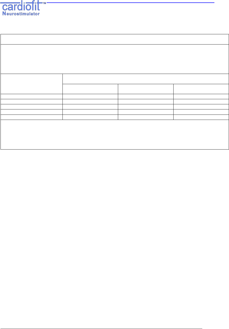
RU-53-001 k 39
Recommended separation distances between portable and mobile RF communications equipment and the
Physician Programmer model 5300 & CardioFit-X Ver 8.17
The Physician Programmer model 5300 & CardioFit-X Ver 8.17 are intended for use in an electromagnetic
environment in which radiated RF disturbances are controlled. The customer or the user of the Physician Programmer
model 5300 & CardioFit-X Ver 8.17can help prevent electromagnetic interference by maintaining a minimum distance
between portable and mobile RF communications equipment (transmitters) and the Physician Programmer model
5300 & CardioFit-X Ver 8.17 as recommended below, according to the maximum output power of the communications
equipment. Separation distance according to frequency of transmitter
m
Rated maximum output power
of transmitter
W 150 kHz to 80 MHz
d = 1.2 √P 80 MHz to 800 MHz
d = 1.2 √P 800 MHz to 2,5 GHz
d = 2.3 √P
0.01 0.12 0.12 0.23
0.1 0.38 0.38 0.73
1 1.2 1.2 2.3
10 3.8 3.8 7.2
100 12 12 23
For transmitters rated at a maximum output power not listed above, the recommended separation distance d in meters
(m) can be estimated using the equation applicable to the frequency of the transmitter, where P is the maximum
output power rating of the transmitter in watts (W) according to the transmitter manufacturer.
NOTE 1 At 80 MHz and 800 MHz, the separation distance for the higher frequency range applies.
NOTE 2 These guidelines may not apply in all situations. Electromagnetic propagation is affected by absorption and
reflection from structures, objects and people.
BioControl Medical BCM Ltd.
3 Geron Street, P.O.B 2713
Yehud 56217, ISRAEL
Tel: +972 3 6322126
Fax: +972 3 6322125
Email: info@biocontrol.co.il
The system and its use for treatment of cardiological pathologies is
protected under one or more of United States patents nos. 6,600,954,
6,684,105, 7561922, 7627384, 7634317 and 7,346,398, as well as
corresponding international patents. Other patents are pending.
CAUTION - Investigational Device.
Limited By Federal Law To Investigational Use.
Hereby, BioControl Medical BCM Ltd., declares that CardioFit™
Neurostimulator is in compliance with the essential requirements and
other relevant provisions of Directive 1999/5/EC
© BioControl Medical BCM Ltd. All rights reserved
MedNet GmbH
Borkstrasse 10
48163 Münster, Germany
Tel: +49 2513 22660, Fax: +49 2513 226622
www.medneteurope.com
Year of
authorization:
2008
0344