BIOTRONIK SE and KG ICSPGH Programmer for implantable Pacemaker / ICD User Manual
BIOTRONIK SE & Co. KG Programmer for implantable Pacemaker / ICD
UserManual.wiki
>
BIOTRONIK SE and KG
>
ICSPGH User Manual
Manual
Navigation menu
Upload a User Manual
Namespaces
Wiki Guide
HTML
PDF
Info
Views
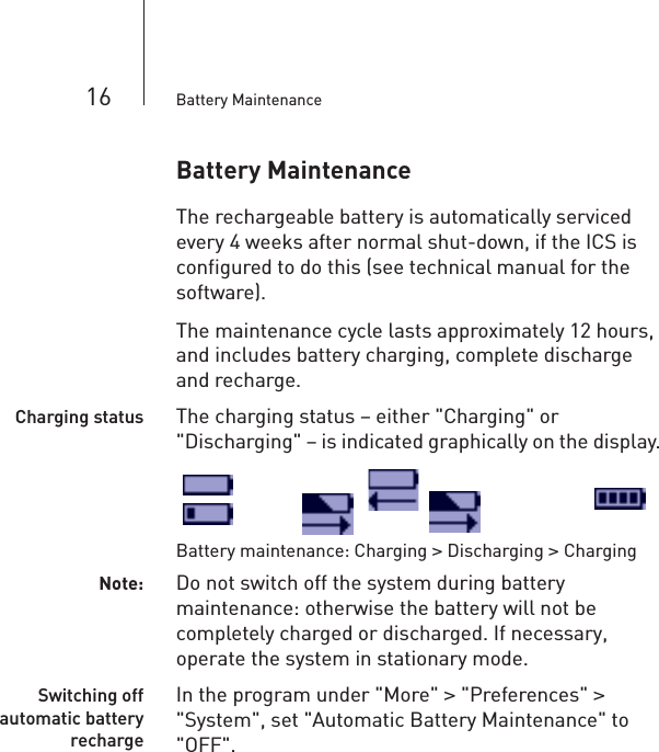
User Manual
Discussion / Help
Navigation
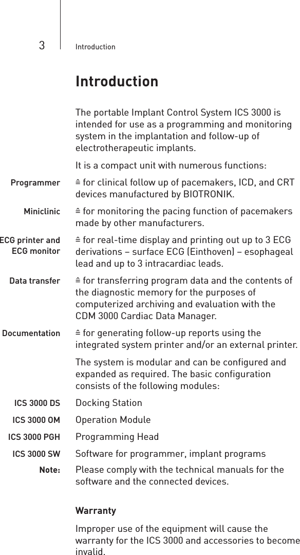
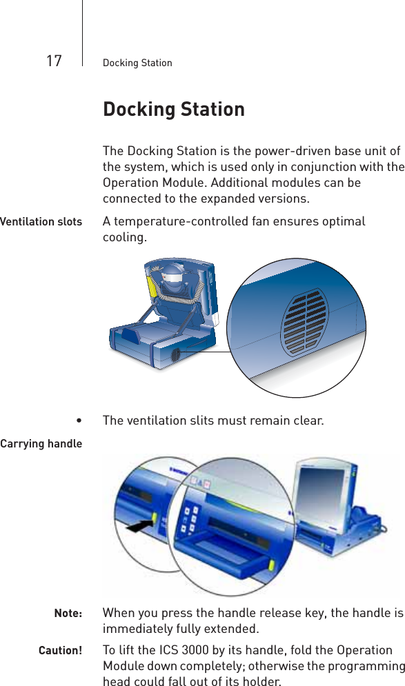
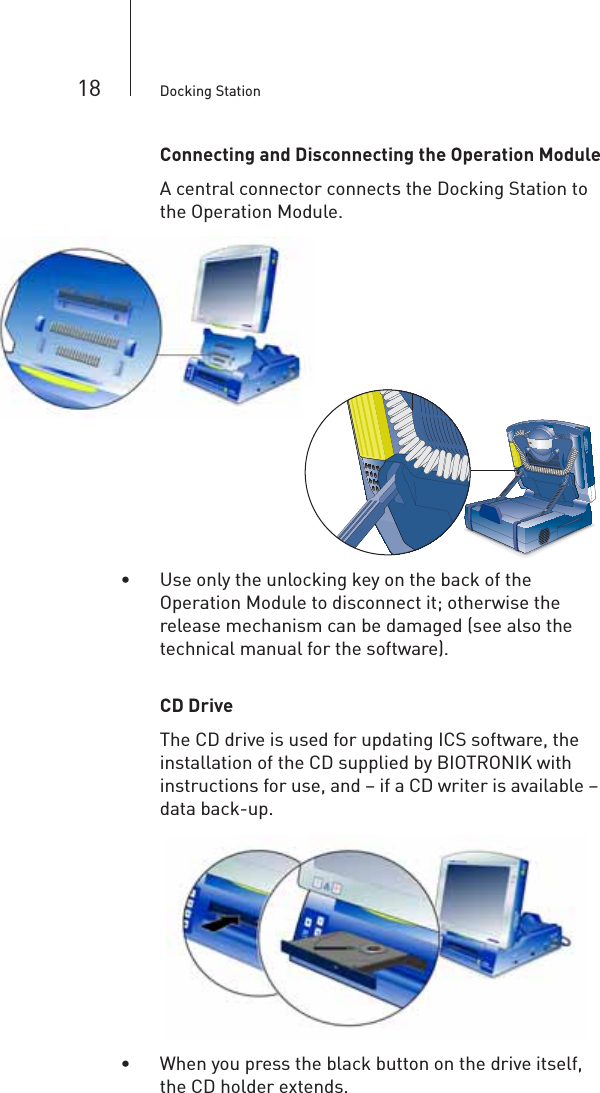
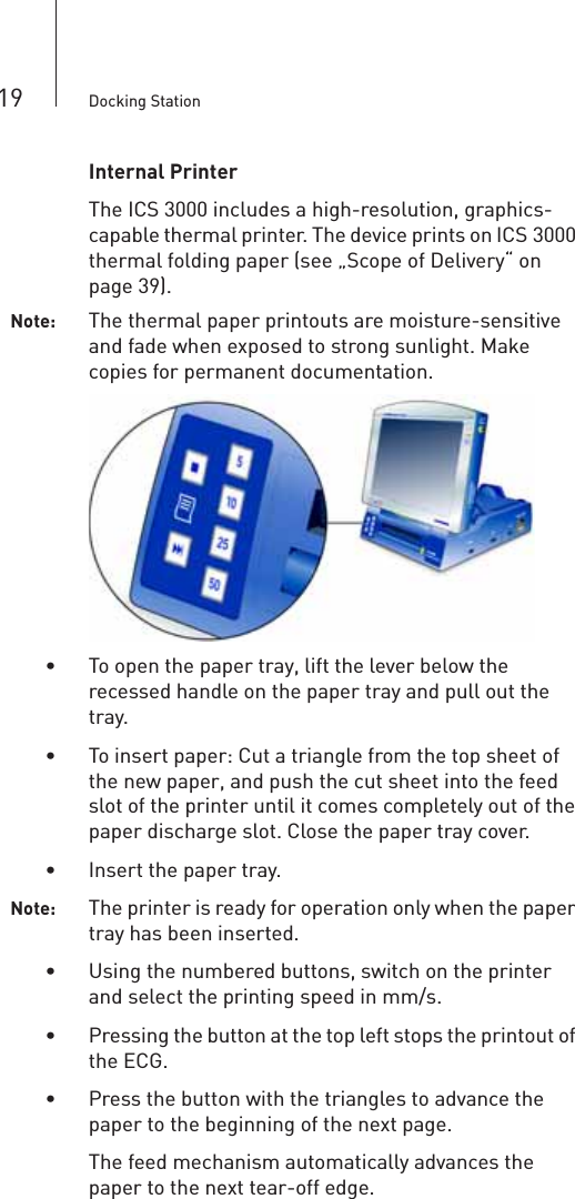
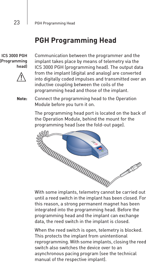
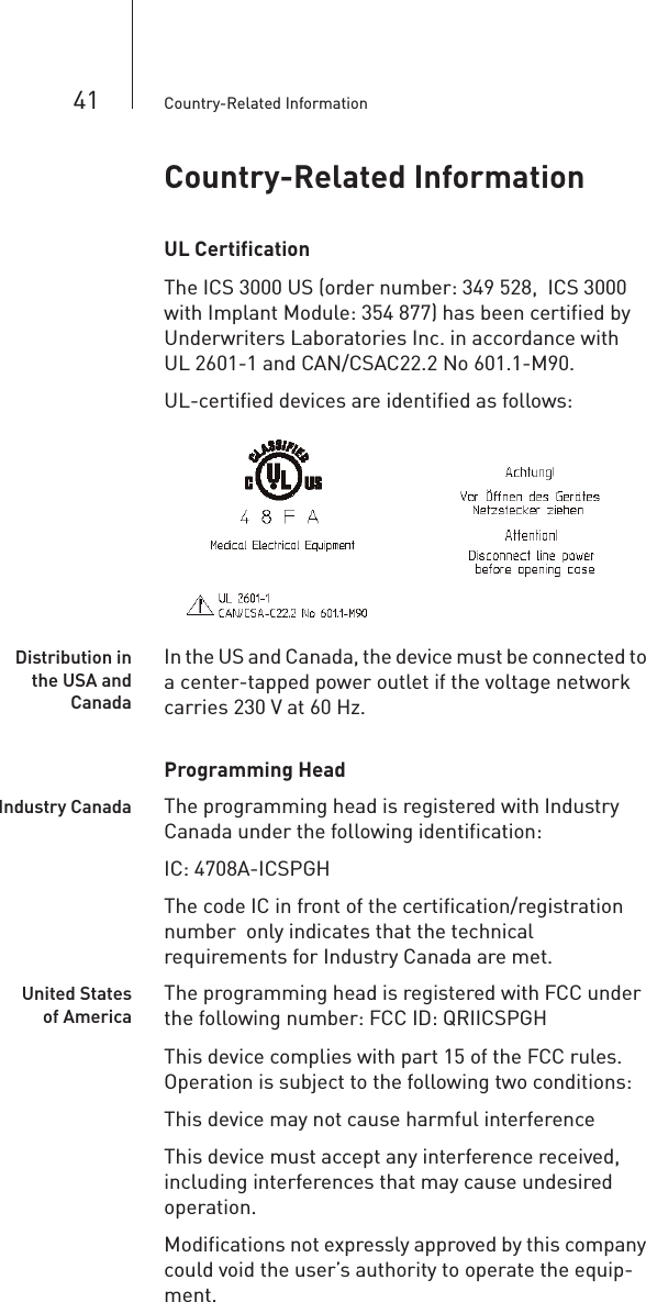
![24 PGH Programming HeadNote: Each programming head features a diagram of the implant to assist in positioning the head. Silicone nubs on the underside prevent the head from slipping.Caution! To program and interrogate the implant, the programming head is brought into physical contact with the patient. The programming head contains a strong magnet. Do not place it close to magnetically sensitive objects such as computer diskettes or wristwatches.• If you are programming the implant under sterile conditions, operate the programming head with a sterile cover (see „Optional Accessories“ on page 40).The LED at the front of the programming head indicates the telemetry contact to the implant:Green LED Telemetry contact optimalYellow LED Telemetry contact in limit value range (implant dependent)Red LED Telemetry contact disturbedLED off No telemetry contact[Safe Program] The PGH 3000 programming head is equipped with its own safe program button. This function can be started directly with top priority from any application if the programming head is positioned above the implant; the button has the same function as the safe program button on the Operation Module. See „Emergency Programs“ on page 29.WARNING! Use the safe program function only under the direct supervision of a physician.](https://usermanual.wiki/BIOTRONIK-SE-and-KG/ICSPGH/User-Guide-831546-Page-27.png)
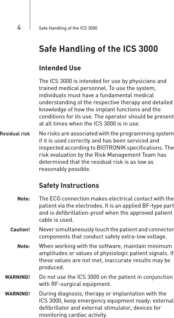
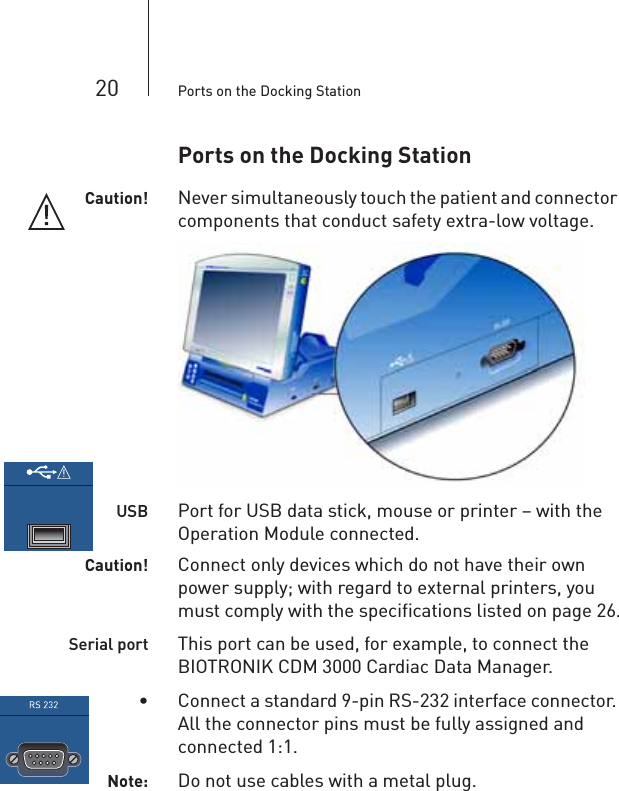
![35 Technical DataTechnical DataICS 3000: General InformationDimensions [mm] 322*168*332 (W*H*D)Safety class I (DIN EN 60601-1, Section 5.1Protection degree IP 20, IEC 60529Protection degreefor anestheticsNone; DIN EN 60601-1, Section 39Operating mode Continuous operationPermissible Environmental ConditionsOperation StorageTemperature [°C] 10–40 0–50Relative Humidity[%]25 – 95 35 – 75No condensationAir pressure [hPa] 700 – 1060Operation Module: General InformationDimensions [mm] 318*85*270 (W*H*D)Weight [kg] 3,2Operating voltage[V]9.6; DCMax. power [W] 30, not including the battery chargeAverage power [W] 20, not including the battery chargeSerial port 1; includes IrDAUSB port 1Rechargeable BatteryType NiMH (HHR-380AB L2x2+L2x2)Voltage [V] 9,6Capacity [Ah] 3,8Operating time[hrs]1,5Battery monitoring Gas gauge, battery level monitoring](https://usermanual.wiki/BIOTRONIK-SE-and-KG/ICSPGH/User-Guide-831546-Page-38.png)
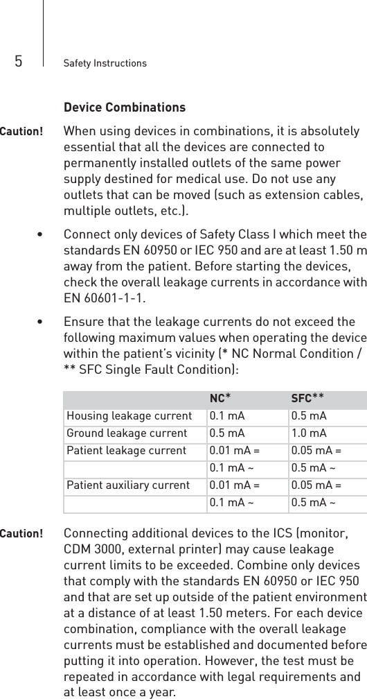
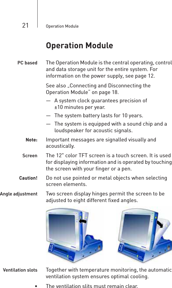
![36 Technical DataLCD screenType TFT; colorSize ["] 12.1; active diagonalResolution [dpi] 800*600; SVGABrightness(programmable)80 cd/m2; with battery operation (software-dependent)200 cd/m2; with battery operation (software-dependent)ECG module: General InformationProtection degree BF, EN 60601-1, Section 5.2Power consumption[W]0.7; maximumMore Defibrillation-proofECG module: ECG FunctionsLeads 3, EinthovendB Common-mode rejection and crosstalk attenuation60; at 50 Hz and input resistance <100 kzInput alternatingcurrent [mV]±25PermissibleDC offset [mV]±300Amplitudetolerance [%]±5; in a frequency range of 5 to 50 Hz; further requirements as specified in AAMI EC 11 1991A/D converter 12 bitScan rate [Hz] 500 ... 1000, for ECG data (software-dependent)Resolution [µV] 1,5Noise [µV] <20Frequency range[Hz]0,6 ... 150; +0/-3 dB for the leadsOvermodulationdisplayContinuous signal line at the upper or lower limit of the ECG fieldECG port Redel plug, 14-pin](https://usermanual.wiki/BIOTRONIK-SE-and-KG/ICSPGH/User-Guide-831546-Page-39.png)
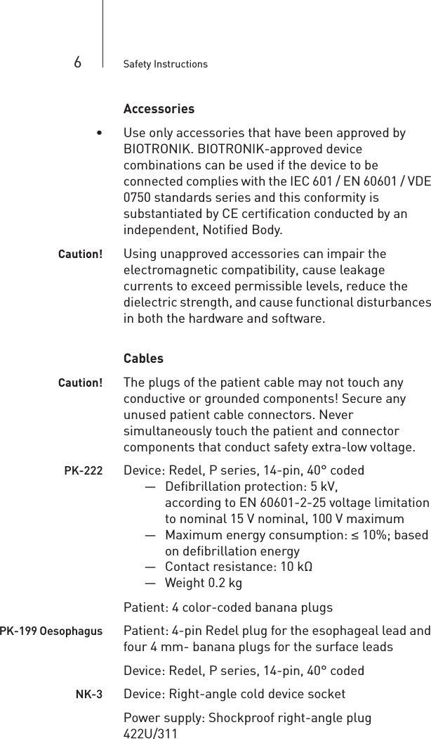
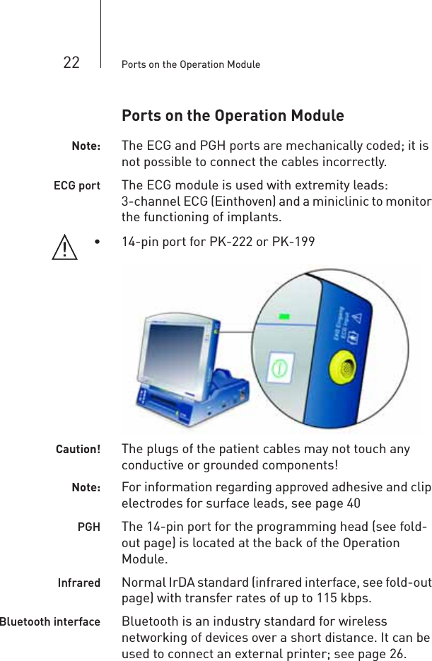
![37 Technical DataMiniclinicStimulation modes Single- and multi-chamberPacing rate [ppm] 30 … 180; ±2 Period[ms]333 … 2000; 2 ±4 Pulse width (A+V)[ms]0,1 … 2,5; 0,05 ±0,05 AV conduction time[ms]50 … 300; 2 ±4 MiniclinicTrigger level [mV]2 … 150; 2 ±4 PGH Programming HeadICS 3000PGH Spiral cable, extendable to approx. 2.30 metersICS 3000PGH Straight cable, 2.1 metersStraight cable, 2.9 metersDimensions [mm] 142*97*42 (W*H*D)Weight [kg] 0,5PGH connection Redel plug, 14-pinProtection degree IP 30Protection degreefor application partType BMagnetic fluxdensity [mT]>2.0 at 60 mm distance>20.0 at 10 mm distance30.0 at 0 mm distanceDocking Station: General InformationDimensions [mm] 284*103*322 (W*H*D)Weight [kg] 3,8Cooling with fanFan control temperature-controlled](https://usermanual.wiki/BIOTRONIK-SE-and-KG/ICSPGH/User-Guide-831546-Page-40.png)
![38 Technical DataPower Supply Type Primary clocked broadband power supplyMains voltage [V],Frequency [Hz]100 – 115 V ± 10% / 60 Hz / 1.2 A / AC220 – 230 V ± 10% / 50 Hz / 0.6 A / ACSafety class I, DIN EN 60601-1, Sec. 5.1Fuse [A] 3.15 surge-proofPower [ W ] Continuous power: 100Short-term maximum: 140Charging CircuitType Switch mode charging circuit corresponding to battery typeSafety switch To prevent overloading and excessive temperatureRecharging time[hrs]4; charging with 1/3 CInternal PrinterPower [ W ] Controller and on standby: 1Thermoline and motor: 50Type of printer Thermal printerResolution[dots/mm]8Paper width [mm] 112Printing width[mm]104Feed rate [mm/s] 5, 10, 25, 50, for graphics as wellFeed ratetolerance [%]±2,5;Maximum absolute error over 100 mm printout](https://usermanual.wiki/BIOTRONIK-SE-and-KG/ICSPGH/User-Guide-831546-Page-41.png)
![40 Optional AccessoriesOptional AccessoriesApproved ECG ElectrodesAdhesiveelectrodesKendall ARBO H34 SGKendall ARBO H68SKINTACT T 60Dahlhausen Type 454Dahlhausen Type 460Clip electrode GOLMED G 502Esophageallead Osypka TO 4, 10.5 FOrder numberM 50 Permanent magnetMagnetic flux density: 12.5 min. [mT]Dimensions: 60*17*26 (W*H*D) [mm]Weight: 0.185 kg112149ICS 3000PGH Straight cable, 2.1 meters 350103Straight cable, 2.9 meters 355547NK-11 / 3 m Power supply cord for the US;A PE conductor compliant with UL 2601-1;Device: Right-angle socketPower supply: Right-angle plug128865NK-16-GB / 2 meters Power supply cord for the United Kingdom 330705 NK-21-AU,UY / 2.5 meters Power supply cord for Australia and Uruguay 339035 NK-22-AR / 2.5 meters Power supply cord for Argentina 339039NK-26-CL, IT / 2.5 meters Power supply cord for Chile and Italy 339043 PK-199 Oesophagus/2.8 meters Patient cable for the esophageal lead 355373PK-222-US / 2.8 m Same as the PK-222-EU with country-specific color coding of the banana plugs 335281Sterile cover 1 Sterile cover for ICS 3000 PGH; single-use, cannot be re-sterilized 340287Rechargeable battery, NiMH 9.6 V Replaceable rechargeable battery for the Operation Module 336549](https://usermanual.wiki/BIOTRONIK-SE-and-KG/ICSPGH/User-Guide-831546-Page-43.png)
![43 Electromagnetic CompatibilityRecommended Safety Distances (Table 206)• Safety distances help prevent interference if you maintain a minimum distance between transmitters such as mobile RF telecommunication devices and the ICS 3000. The necessary distance depends on the respective power output of the transmitter.Note: At 80 MHz and at 800 MHz, the higher frequency range applies.• For transmitters whose maximum output power is not indicated in the table, the recommended safety distance d can be calculated in meters using an equation that is suitable for the respective transmission frequency range. P is the maximum output power of the transmitter in watts [W] according to the specification of the transmitter’s manufacturer.Transmission Frequency 150 kHz to 80 MHz 80 MHz up to 800 MHz 800 MHz to 2.5 GHzMaximum output power of the transmitter [W]Safety distance [m]0,01 0,12 0,12 0,240,1 0,37 0,37 0,741 1,17 1,17 2,3410 3,70 3,70 7,40100 11,7 11,7 23,4Transmission Frequency 150 kHz to 80 MHz 80 MHz up to 800 MHz 800 MHz to 2.5 GHzEquationd117P,= d117P,= d234P,=](https://usermanual.wiki/BIOTRONIK-SE-and-KG/ICSPGH/User-Guide-831546-Page-46.png)