BIOTRONIK SE and KG ICSPGH Programmer for implantable Pacemaker / ICD User Manual
BIOTRONIK SE & Co. KG Programmer for implantable Pacemaker / ICD
Manual
ICS 3000
Implant Control System 3000
Cardiac Rhythm Management
Technical Manual
sbiotronik
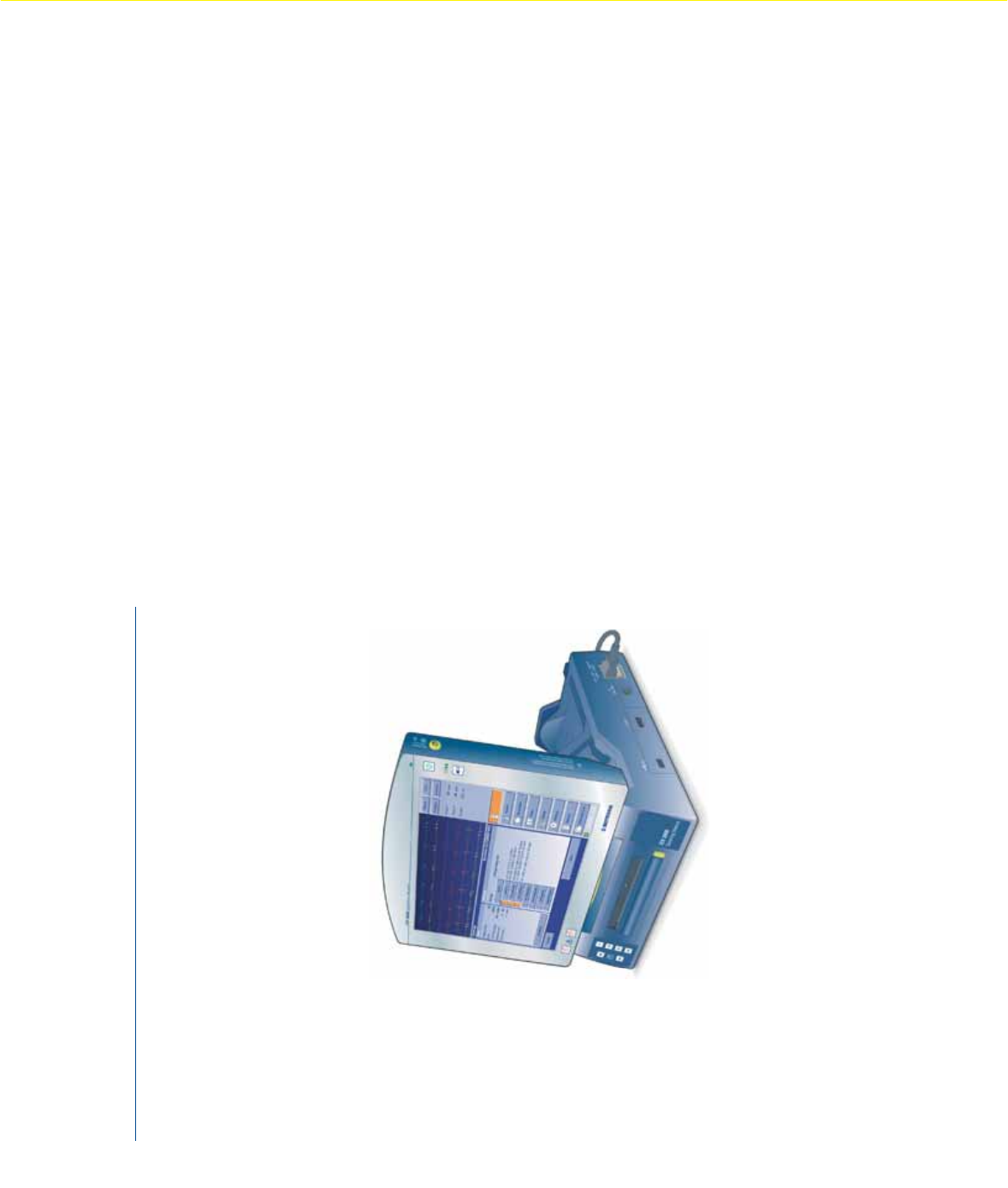
Implant Control System ICS 3000
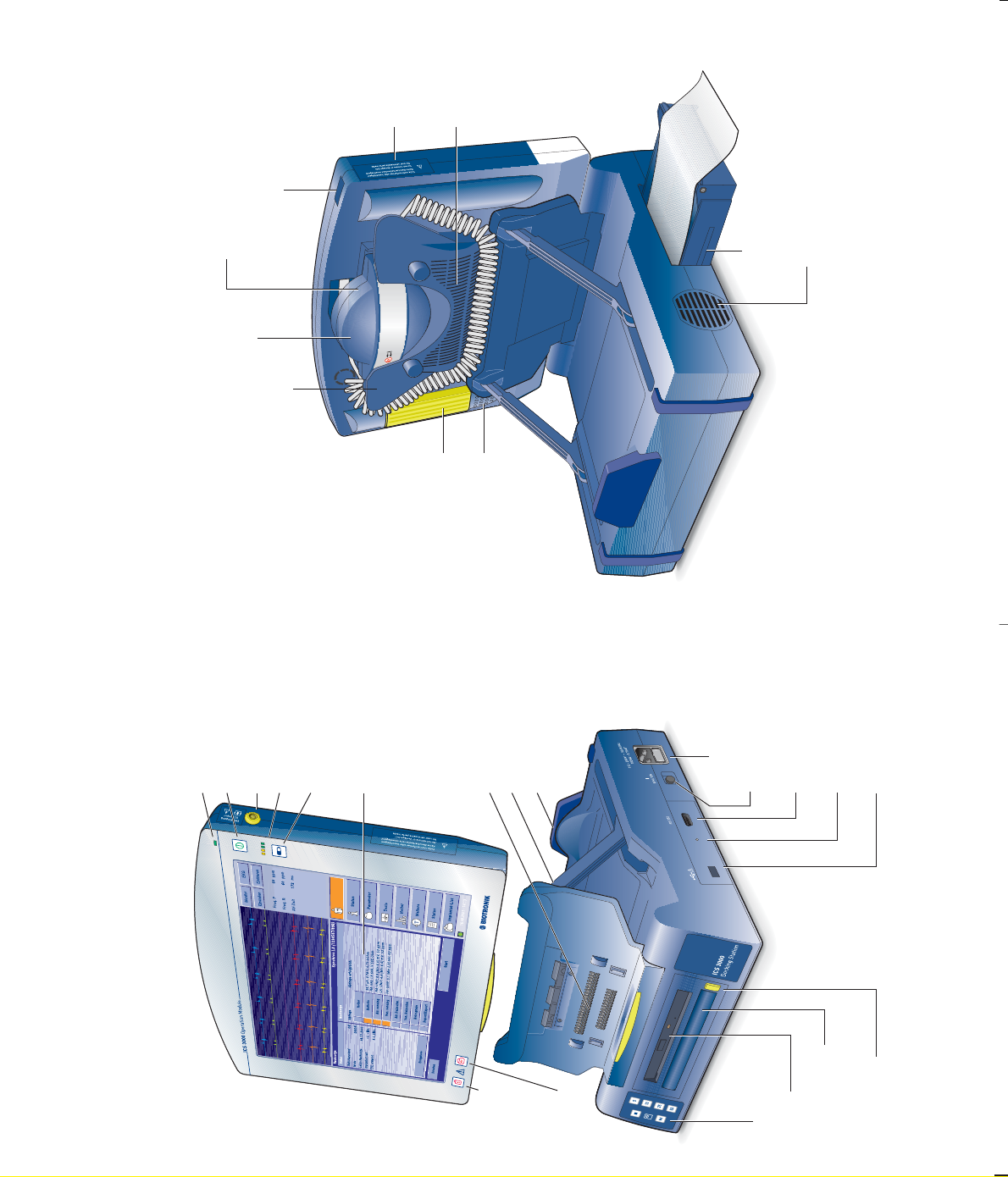
USB port
Unlocking key
PGH mount
Covered: PGH port
Infrared interface
Ventilation slots
Paper tray
Release key
for the handle
Operation Module
Operational display
On/Off button
ECG port
LEDs: battery charge
Battery charge button
Screen
Emergency
shock
button
Safe
programm
button
Central connect or
Screen display hinges
Base
ON switch
Power supply
Serial port
Docking
Station
Printer keypad
CD drive
Carrying handle Operational display
Covered:
rechargeable
battery
Optional:
bluetooth
interface
Ventilation slots
PGH programming head

336 832/F/707
This product conforms with the directives
90/385/EEC relating to active implantable
medical devices and 99/5/EC on radio
equipment and telecommunication terminal
equipment. It was approved by independent
Notified Bodies and is therefore designated
with the CE mark. The product can be used
in all European Union countries as well
as in countries that recognize the above-
mentioned directives.
BIOTRONIK GmbH & Co. KG
Woermannkehre 1
12359 Berlin · Germany
Tel +49 (0) 30 68905-0
Fax +49 (0) 30 6852804
sales@biotronik.com
www.biotronik.com
sbiotronik

1Contents
Contents
Introduction . . . . . . . . . . . . . . . . . . . . . . . . . . . . . . . . . . . . . . . . . . . . 3
Safe Handling of the ICS 3000 . . . . . . . . . . . . . . . . . . . . . . . . . . . . . 4
Intended Use . . . . . . . . . . . . . . . . . . . . . . . . . . . . . . 4
Safety Instructions . . . . . . . . . . . . . . . . . . . . . . . . . 4
Instructions for use . . . . . . . . . . . . . . . . . . . . . . . . . 9
Power Supply . . . . . . . . . . . . . . . . . . . . . . . . . . . . . . . . . . . . . . . . . . 12
Switching On the System . . . . . . . . . . . . . . . . . . . . 12
Switching Off the System . . . . . . . . . . . . . . . . . . . . 14
Battery Maintenance . . . . . . . . . . . . . . . . . . . . . . . . 16
Docking Station . . . . . . . . . . . . . . . . . . . . . . . . . . . . . . . . . . . . . . . . . 17
Ports on the Docking Station . . . . . . . . . . . . . . . . . 20
Operation Module . . . . . . . . . . . . . . . . . . . . . . . . . . . . . . . . . . . . . . . 21
Ports on the Operation Module . . . . . . . . . . . . . . . 22
PGH Programming Head . . . . . . . . . . . . . . . . . . . . . . . . . . . . . . . . . 23
Using Basic Functions . . . . . . . . . . . . . . . . . . . . . . . . . . . . . . . . . . . 26
External Printer . . . . . . . . . . . . . . . . . . . . . . . . . . . 26
ICS 3000 Software . . . . . . . . . . . . . . . . . . . . . . . . . . 27
ECG Recorder and ECG Monitor . . . . . . . . . . . . . . 27
Recording ECGs and IEGMs . . . . . . . . . . . . . . . . . . 28
Miniclinic . . . . . . . . . . . . . . . . . . . . . . . . . . . . . . . . . 28
Data Transfer . . . . . . . . . . . . . . . . . . . . . . . . . . . . . . 29
Documentation . . . . . . . . . . . . . . . . . . . . . . . . . . . . 29
Interrogating and Programming the Implant . . . . 29
Emergency Programs . . . . . . . . . . . . . . . . . . . . . . . 29
Non-invasive Programmed Stimulation . . . . . . . . 31
Analog Telemetry . . . . . . . . . . . . . . . . . . . . . . . . . . 31
The EMI Test . . . . . . . . . . . . . . . . . . . . . . . . . . . . . . 31
336832--F

2Contents
Care and Maintenance . . . . . . . . . . . . . . . . . . . . . . . . . . . . . . . . . . . 32
Cleaning and Disinfection . . . . . . . . . . . . . . . . . . . . 32
Sterilization . . . . . . . . . . . . . . . . . . . . . . . . . . . . . . . 33
Maintenance . . . . . . . . . . . . . . . . . . . . . . . . . . . . . . 33
Changing a Fuse . . . . . . . . . . . . . . . . . . . . . . . . . . . 34
Disposal . . . . . . . . . . . . . . . . . . . . . . . . . . . . . . . . . . 34
Technical Data . . . . . . . . . . . . . . . . . . . . . . . . . . . . . . . . . . . . . . . . . . 35
Scope of Delivery . . . . . . . . . . . . . . . . . . . . . . . . . . . . . . . . . . . . . . . 39
Standard . . . . . . . . . . . . . . . . . . . . . . . . . . . . . . . . . 39
Optional Accessories . . . . . . . . . . . . . . . . . . . . . . . 40
Approved ECG Electrodes . . . . . . . . . . . . . . . . . . . . 40
Country-Related Information . . . . . . . . . . . . . . . . . . . . . . . . . . . . . 41
Electromagnetic Compatibility . . . . . . . . . . . . . . . . . . . . . . . . . . . . 42
Symbol Index . . . . . . . . . . . . . . . . . . . . . . . . . . . . . . . . . . . . . . . . . . . 46
Index . . . . . . . . . . . . . . . . . . . . . . . . . . . . . . . . . . . . . . . . . . . . . . . . . 49

3Introduction
Introduction
The portable Implant Control System ICS 3000 is
intended for use as a programming and monitoring
system in the implantation and follow-up of
electrotherapeutic implants.
It is a compact unit with numerous functions:
Programmer … for clinical follow up of pacemakers, ICD, and CRT
devices manufactured by BIOTRONIK.
Miniclinic … for monitoring the pacing function of pacemakers
made by other manufacturers.
ECG printer and
ECG monitor
… for real-time display and printing out up to 3 ECG
derivations – surface ECG (Einthoven) – esophageal
lead and up to 3 intracardiac leads.
Data transfer … for transferring program data and the contents of
the diagnostic memory for the purposes of
computerized archiving and evaluation with the
CDM 3000 Cardiac Data Manager.
Documentation … for generating follow-up reports using the
integrated system printer and/or an external printer.
The system is modular and can be configured and
expanded as required. The basic configuration
consists of the following modules:
ICS 3000 DS Docking Station
ICS 3000 OM Operation Module
ICS 3000 PGH Programming Head
ICS 3000 SW Software for programmer, implant programs
Note: Please comply with the technical manuals for the
software and the connected devices.
Warranty
Improper use of the equipment will cause the
warranty for the ICS 3000 and accessories to become
invalid.

4Safe Handling of the ICS 3000
Safe Handling of the ICS 3000
Intended Use
The ICS 3000 is intended for use by physicians and
trained medical personnel. To use the system,
individuals must have a fundamental medical
understanding of the respective therapy and detailed
knowledge of how the implant functions and the
conditions for its use. The operator should be present
at all times when the ICS 3000 is in use.
Residual risk No risks are associated with the programming system
if it is used correctly and has been serviced and
inspected according to BIOTRONIK specifications. The
risk evaluation by the Risk Management Team has
determined that the residual risk is as low as
reasonably possible.
Safety Instructions
Note: The ECG connection makes electrical contact with the
patient via the electrodes. It is an applied BF-type part
and is defibrillation-proof when the approved patient
cable is used.
Caution! Never simultaneously touch the patient and connector
components that conduct safety extra-low voltage.
Note: When working with the software, maintain minimum
amplitudes or values of physiologic patient signals. If
these values are not met, inaccurate results may be
produced.
WARNING! Do not use the ICS 3000 on the patient in conjunction
with RF-surgical equipment.
WARNING! During diagnosis, therapy or implantation with the
ICS 3000, keep emergency equipment ready: external
defibrillator and external stimulator, devices for
monitoring cardiac activity.

5Safety Instructions
Device Combinations
Caution! When using devices in combinations, it is absolutely
essential that all the devices are connected to
permanently installed outlets of the same power
supply destined for medical use. Do not use any
outlets that can be moved (such as extension cables,
multiple outlets, etc.).
• Connect only devices of Safety Class I which meet the
standards EN 60950 or IEC 950 and are at least 1.50 m
away from the patient. Before starting the devices,
check the overall leakage currents in accordance with
EN 60601-1-1.
• Ensure that the leakage currents do not exceed the
following maximum values when operating the device
within the patient’s vicinity (* NC Normal Condition /
** SFC Single Fault Condition):
Caution! Connecting additional devices to the ICS (monitor,
CDM 3000, external printer) may cause leakage
current limits to be exceeded. Combine only devices
that comply with the standards EN 60950 or IEC 950
and that are set up outside of the patient environment
at a distance of at least 1.50 meters. For each device
combination, compliance with the overall leakage
currents must be established and documented before
putting it into operation. However, the test must be
repeated in accordance with legal requirements and
at least once a year.
NC*SFC**
Housing leakage current 0.1 mA 0.5 mA
Ground leakage current 0.5 mA 1.0 mA
Patient leakage current 0.01 mA = 0.05 mA =
0.1 mA ~ 0.5 mA ~
Patient auxiliary current 0.01 mA = 0.05 mA =
0.1 mA ~ 0.5 mA ~

6Safety Instructions
Accessories
• Use only accessories that have been approved by
BIOTRONIK. BIOTRONIK-approved device
combinations can be used if the device to be
connected complies with the IEC 601 / EN 60601 / VDE
0750 standards series and this conformity is
substantiated by CE certification conducted by an
independent, Notified Body.
Caution! Using unapproved accessories can impair the
electromagnetic compatibility, cause leakage
currents to exceed permissible levels, reduce the
dielectric strength, and cause functional disturbances
in both the hardware and software.
Cables
Caution! The plugs of the patient cable may not touch any
conductive or grounded components! Secure any
unused patient cable connectors. Never
simultaneously touch the patient and connector
components that conduct safety extra-low voltage.
PK-222 Device: Redel, P series, 14-pin, 40° coded
— Defibrillation protection: 5 kV,
according to EN 60601-2-25 voltage limitation
to nominal 15 V nominal, 100 V maximum
— Maximum energy consumption: l10%; based
on defibrillation energy
—Contact resistance: 10kz
— Weight 0.2 kg
Patient: 4 color-coded banana plugs
PK-199 Oesophagus Patient: 4-pin Redel plug for the esophageal lead and
four 4 mm- banana plugs for the surface leads
Device: Redel, P series, 14-pin, 40° coded
NK-3 Device: Right-angle cold device socket
Power supply: Shockproof right-angle plug
422U/311

7Safety Instructions
Operating conditions
Caution! The ICS may be operated only in areas used for
medical purposes (in accordance with DIN VDE
0107:1994). Do NOT operate the ICS 3000 in areas
where there is a risk of explosion.
Note: The ICS 3000 is designed to be operated and stored in
an enclosed area.
• Operate the ICS 3000 and its individual components
only after placing it on a stable, level surface (e.g., a
table).
Caution! Connect only the BIOTRONIK power supply cable to
the power supply; never use any other cables for the
ICS 3000.
WARNING! Never connect the ICS 3000 to the patient at the same
time you are using electrosurgical instruments (such
as an electrocautery). This might harm the patient
and/or cause improper or unpredictable functioning of
the device.
WARNING! Under no circumstances should you attempt to
change settings by selecting the parameter(s) several
times in rapid succession. This could produce
unintended results.
Caution! The ICS 3000 has a touch screen for all input. Exercise
care in configuring the settings, so that you do not
activate an undesired function unintentionally.
WARNING! Use the safe program function only under the direct
supervision of a physician.
WARNING! Keep an external defibrillator available when using
the NIPS function.

8Safety Instructions
Electromagnetic Compatibility
Note: The ICS 3000 is protected against interference due to
electromagnetic radiation, electrostatic discharge,
and other disturbances, including those associated
with electric power lines. Interference from the
ICS 3000 has also been minimized. Thus, the ICS 3000
meets the requirements of EN 60601-1-2 in every
respect.
Note: The electromagnetic compatibility of the device meets
the requirements specified in the standards. Avoid
strong electrical, magnetic, or electromagnetic fields.
However, strong electromagnetic fields can be
generated by electrical devices and lines (e.g. power
lines, electric motors, PCs, monitors, etc.) in the
immediate vicinity of ICS 3000, which impair the
functioning of ICS 3000. This could lead to an
interruption in the telemetric connection to the
implant, to an erroneous display of the ECG or IEGM,
to malfunctions in operating procedures or similar
problems. If it is not possible to switch off the
interfering device, maintain a minimum distance to
the electromagnetic environment as specified in the
appendix of this manual (see page 42).
Caution! Pay attention to the following device disturbances:
— An unexpected power-down of the device;
— Detection of spontaneous cardiac events not
displayed on the ECG/IEGM screen;
— Interference from an indeterminate source.
Action to take — Turn off the electrical device causing the
interference.
— Remove the source of the interference from the
vicinity of the ICS 3000.
— Move the ICS 3000 away from the vicinity of the
source of interference.
— Switch the ICS 3000 off and then on again.
— If the interference persists, contact BIOTRONIK or
an authorized representative.

9Instructions for use
Instructions for use
Caution! The ICS 3000 programming and monitoring system is
a sophisticated precision instrument and must
therefore be handled with care. The ICS 3000 can be
damaged by improper handling. Transport it carefully.
Mechanical impact (if, for example, the ICS 3000 or
the programming head is put down hard or dropped)
can impair functioning. In this case, have the device
checked by BIOTRONIK or an authorized
representative.
Note: The ICS 3000 with its OM, DS, and PGH components
may be operated in the vicinity of the patient.
Note: System error messages are generated optically and/
or acoustically.
Note: The ICS 3000 may NOT be used as a life support
system.
Note: The ICS 3000 is portable. The Docking Station and
Operation Module can be used while plugged into the
power supply. The Operation Module can also be used
in wireless mode (with its rechargeable battery pack).
Caution! Detach the Operation Module only by using the release
button on the back of the Operation Module; otherwise
the locking mechanism will be damaged. Follow the
instructions in the software user manual.
Note: The device contains measurement functions that
indirectly serve specific diagnostic purposes.
Caution! Do not operate or store the ICS 3000 in direct sunlight
or under similar heat sources (e.g., halogen lighting).
Also, do not operate it near heaters or other sources
of heat. Exposure to high heat can cause damage.
Caution! Never close or block the ventilation slots on the back
of the device.
Caution! Never remove the label from the housing of the
ICS 3000.

10 Instructions for use
Caution! Never use organic solvents such as ether or acetone
to clean the device. Always ensure that no liquids can
penetrate the device.
Caution! Never sterilize the ICS 3000.
Caution! Do not operate the ICS 3000 near flammable or
explosive materials.
Caution! The ICS 3000 may be used only in spaces suited for
medical purposes and equipped with grounded
alternating current.
Connecting the programmer to the patient
• When used in the operating room, cover the
programming head and the cable connecting it to the
ICS 3000 with a sterile cover.
Caution! Use the safe program function only under the direct
supervision of a physician.
Caution! The ICS 3000 stores programming and diagnostic data
in its memory. In the event of a loss of power or
power-down during operation, all data in the memory
could be lost.
External Defibrillation
Caution! During defibrillation, do not touch the programmer
and its accessories that are attached to the patient.
Caution! The ICS 3000 is protected against defibrillation
current. However, damage to devices connected to
intracardiac leads cannot be ruled out.
• Place the electrodes of an external defibrillator at
least 10 cm away from the implanted electrodes.
• Set the energy level no higher than that required to
achieve defibrillation.
• After external defibrillation, check all the functions of
the ICS 3000; see Inspection B.

11 Instructions for use
Storage and shipping
• Use the provided packaging when returning devices to
the manufacturer. The same environmental conditions
apply to both storage and shipping (see „Technical
Data“ on page 35).
• The thermal paper printouts are moisture-sensitive
and fade when exposed to strong sunlight. Make
copies for permanent documentation.
Self-test
After it has been turned on, the device carries out self-
tests for approximately 1 minute.
WARNING! The ICS 3000 cannot be used during the self-test. To
ensure the device is always ready for operation, do not
switch it off during an examination.

12 Power Supply
Power Supply
The ICS 3000 has an internal 9.6 V NiMH rechargeable
battery. Nickel metal hydride rechargeable batteries
have a service life of 500 to 700 charging cycles.
Under optimal conditions, the capacity of 3800 mAh
suffices for an uninterrupted system operating time in
modular mode of approximately 1.5 hours.
The power unit supplies all components and
additional modules with electricity. Automatic power
monitoring protects the device from electrical
overload.
Switching On the System
Battery level
indicator
Before switching on the system, you can check the
current battery level with the detached and powered-
down Operation Module.
With more than 130 mA battery power, the LEDs light
up independently.
• If the LEDs do not light up, press the battery level
indicator button: The LEDs that indicate the respective
battery level will light up for 4 seconds.
2 yellow, 2 green Battery level 75% – 100%
2 yellow, 1 green Battery level 50% – 75%
2 yellow Battery level 25% – 50%
1 yellow, flashing Battery level < 25%
Note: The Operation Module sends a report when the battery
level is low (see technical manual for the software).
Save all data and connect the Operation Module to the
Docking Station to recharge the battery pack. If you
fail to connect the Operation Module to the Docking
Station before the battery is completely discharged,
the Operation Module automatically saves the current
data and powers down.
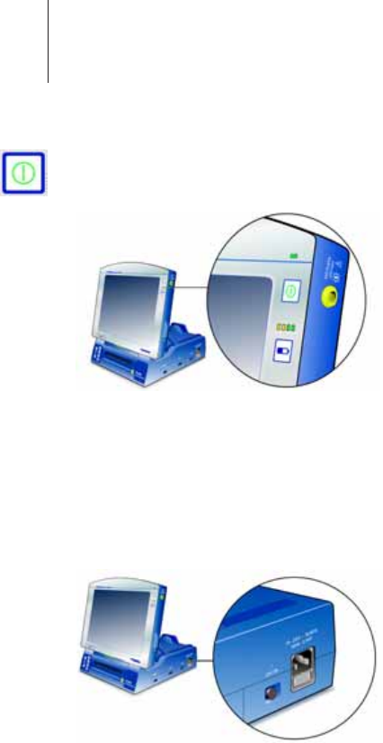
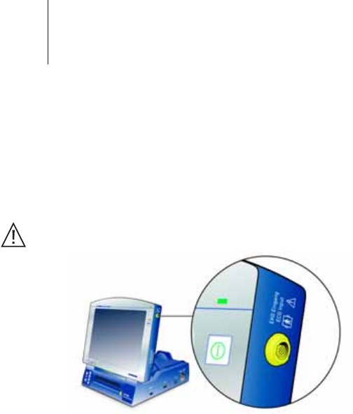
13 Switching On the System
On/Off button Use the On/Off button on the Operation Module to
switch on both components if they are connected to
each other for stationary operation and connected to
the power supply.
When the Docking Station is switched on, the green
LED on the right side of the housing will be
illuminated.
System does not
switch on
If the Operation Module cannot be turned on with its
On/Off button, its battery is completely depleted. In
this case, the Operation Module must be operated on
the Docking Station and must be turned on with the
Docking Station’s On/Off button.
• In emergencies, switch on the docking station as well
as the complete system using the ON switch next to
the power connection socket.
Modular operation If you remove the Operation Module from the Docking
Station, the battery pack will provide power for the
continued uninterrupted operation of the Operation
Module.
The green LED on the Docking Station goes out.
On the Operation Module, an illuminated green LED
and the display illumination indicates readiness for
operation.

14 Switching Off the System
Switching Off the System
Normal shut-down When you press the On/Off button quickly, the
Operation Module switches to standby mode within a
few seconds.
— The data are saved.
— The screen goes black.
— The battery level of the rechargeable battery is
checked; if it is fully charged, the Operation
Module and Docking Station will switch off
automatically after 30 seconds.
If the Operation Module is connected, the system
connected to the power supply and the battery is no
longer fully charged, it will be automatically recharged
(see also „Automatic Battery Recharge“ on page 15).
— The screen goes black and the fan continues to
run.
— The system shuts down completely only after the
battery has been recharged.
Note: After a normal shut-down, the ICS is quickly ready for
operation again: Depending on the pre-defined
setting, a restart takes 30 or 60 seconds.
Forced shut-down If the software does not respond to brief pressure on
the button for normal shut-down, you can force the
system to shut down.
When you press the On/Off button for 3 seconds, the
Operation Module switches itself off immediately.
— Any unsaved data will be lost.
— The battery will not be automatically recharged.
— The subsequent restart takes about 60 seconds.
WARNING! To switch off the device in an emergency, unplug the
device. In an emergency, the device cannot be
switched off effectively using the On/Off button on the
Operation Module, because there is a delay in
switching off. The ON switch on the Docking Station is
used only for switching on the device.

15 Switching Off the System
Automatic Battery Recharge
Automatic battery recharging begins after a normal
shut-down. The recharging status is shown
graphically on the Operation Module display as a
percentage. The LEDs light up in reverse sequence;
see „Battery level indicator“ on page 12.
Depending on the battery level, recharging may take
up to 4 hours. When recharging is completed, the
LEDs go out.
Battery is not
recharged
— The Operation Module and Docking Station are not
connected to each other.
— The battery is of poor quality: for example, it is too
old or has been poorly maintained.
— The ICS underwent a forced shut-down (On/Off
button was pressed longer than 3 seconds).
— The internal operating temperature after
switching on or during operation is too high.
—No power supply
16 Battery Maintenance
Battery Maintenance
The rechargeable battery is automatically serviced
every 4 weeks after normal shut-down, if the ICS is
configured to do this (see technical manual for the
software).
The maintenance cycle lasts approximately 12 hours,
and includes battery charging, complete discharge
and recharge.
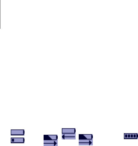
Charging status The charging status – either "Charging" or
"Discharging" – is indicated graphically on the display.
Battery maintenance: Charging > Discharging > Charging
Note: Do not switch off the system during battery
maintenance: otherwise the battery will not be
completely charged or discharged. If necessary,
operate the system in stationary mode.
Switching off
automatic battery
recharge
In the program under "More" > "Preferences" >
"System", set "Automatic Battery Maintenance" to
"OFF".
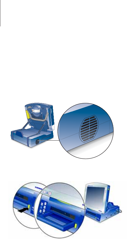
17 Docking Station
Docking Station
The Docking Station is the power-driven base unit of
the system, which is used only in conjunction with the
Operation Module. Additional modules can be
connected to the expanded versions.
Ventilation slots A temperature-controlled fan ensures optimal
cooling.
• The ventilation slits must remain clear.
Carrying handle
Note: When you press the handle release key, the handle is
immediately fully extended.
Caution! To lift the ICS 3000 by its handle, fold the Operation
Module down completely; otherwise the programming
head could fall out of its holder.
18 Docking Station
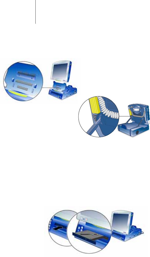
Connecting and Disconnecting the Operation Module
A central connector connects the Docking Station to
the Operation Module.
• Use only the unlocking key on the back of the
Operation Module to disconnect it; otherwise the
release mechanism can be damaged (see also the
technical manual for the software).
CD Drive
The CD drive is used for updating ICS software, the
installation of the CD supplied by BIOTRONIK with
instructions for use, and – if a CD writer is available –
data back-up.
• When you press the black button on the drive itself,
the CD holder extends.
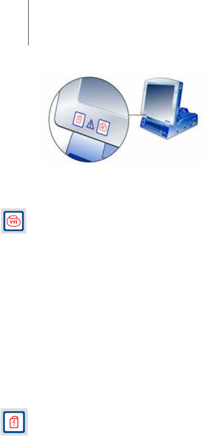
19 Docking Station
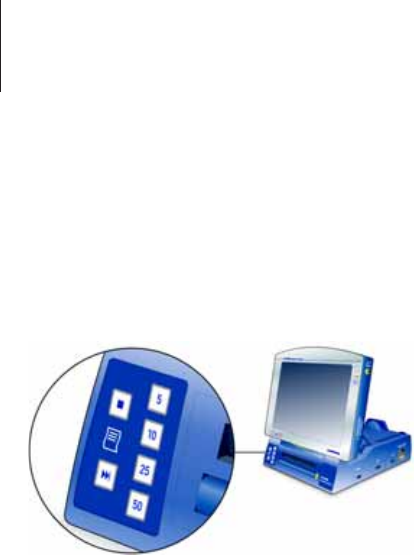
Internal Printer
The ICS 3000 includes a high-resolution, graphics-
capable thermal printer. The device prints on ICS 3000
thermal folding paper (see „Scope of Delivery“ on
page 39).
Note: The thermal paper printouts are moisture-sensitive
and fade when exposed to strong sunlight. Make
copies for permanent documentation.
• To open the paper tray, lift the lever below the
recessed handle on the paper tray and pull out the
tray.
• To insert paper: Cut a triangle from the top sheet of
the new paper, and push the cut sheet into the feed
slot of the printer until it comes completely out of the
paper discharge slot. Close the paper tray cover.
• Insert the paper tray.
Note: The printer is ready for operation only when the paper
tray has been inserted.
• Using the numbered buttons, switch on the printer
and select the printing speed in mm/s.
• Pressing the button at the top left stops the printout of
the ECG.
• Press the button with the triangles to advance the
paper to the beginning of the next page.
The feed mechanism automatically advances the
paper to the next tear-off edge.
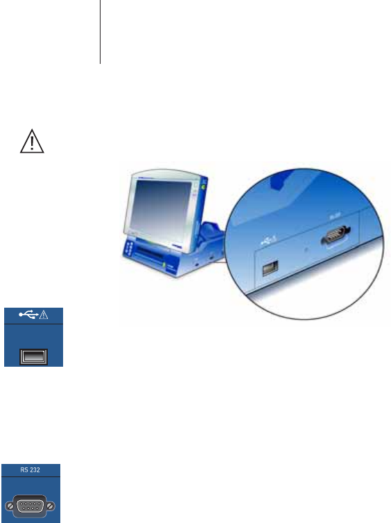
20 Ports on the Docking Station
Ports on the Docking Station
Caution! Never simultaneously touch the patient and connector
components that conduct safety extra-low voltage.
USB Port for USB data stick, mouse or printer – with the
Operation Module connected.
Caution! Connect only devices which do not have their own
power supply; with regard to external printers, you
must comply with the specifications listed on page 26.
Serial port This port can be used, for example, to connect the
BIOTRONIK CDM 3000 Cardiac Data Manager.
• Connect a standard 9-pin RS-232 interface connector.
All the connector pins must be fully assigned and
connected 1:1.
Note: Do not use cables with a metal plug.

21 Operation Module
Operation Module
PC based The Operation Module is the central operating, control
and data storage unit for the entire system. For
information on the power supply, see page 12.
See also „Connecting and Disconnecting the
Operation Module“ on page 18.
— A system clock guarantees precision of
±10 minutes per year.
— The system battery lasts for 10 years.
— The system is equipped with a sound chip and a
loudspeaker for acoustic signals.
Note: Important messages are signalled visually and
acoustically.
Screen The 12" color TFT screen is a touch screen. It is used
for displaying information and is operated by touching
the screen with your finger or a pen.
Caution! Do not use pointed or metal objects when selecting
screen elements.
Angle adjustment Two screen display hinges permit the screen to be
adjusted to eight different fixed angles.
Ventilation slots Together with temperature monitoring, the automatic
ventilation system ensures optimal cooling.
• The ventilation slits must remain clear.
22 Ports on the Operation Module
Ports on the Operation Module
Note: The ECG and PGH ports are mechanically coded; it is
not possible to connect the cables incorrectly.
ECG port The ECG module is used with extremity leads:
3-channel ECG (Einthoven) and a miniclinic to monitor
the functioning of implants.
• 14-pin port for PK-222 or PK-199
Caution! The plugs of the patient cables may not touch any
conductive or grounded components!
Note: For information regarding approved adhesive and clip
electrodes for surface leads, see page 40
PGH The 14-pin port for the programming head (see fold-
out page) is located at the back of the Operation
Module.
Infrared Normal IrDA standard (infrared interface, see fold-out
page) with transfer rates of up to 115 kbps.
Bluetooth interface Bluetooth is an industry standard for wireless
networking of devices over a short distance. It can be
used to connect an external printer; see page 26.
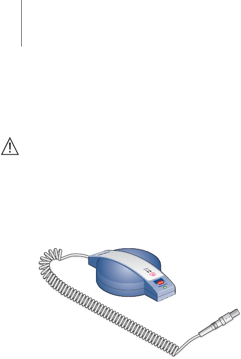
23 PGH Programming Head
PGH Programming Head
ICS 3000 PGH
(Programming
head)
Communication between the programmer and the
implant takes place by means of telemetry via the
ICS 3000 PGH (programming head). The output data
from the implant (digital and analog) are converted
into digitally coded impulses and transmitted over an
inductive coupling between the coils of the
programming head and those of the implant.
Note: Connect the programming head to the Operation
Module before you turn it on.
The programming head port is located on the back of
the Operation Module, behind the mount for the
programming head (see the fold-out page).
With some implants, telemetry cannot be carried out
until a reed switch in the implant has been closed. For
this reason, a strong permanent magnet has been
integrated into the programming head. Before the
programming head and the implant can exchange
data, the reed switch in the implant is closed.
When the reed switch is open, telemetry is blocked.
This protects the implant from unintentional
reprogramming. With some implants, closing the reed
switch also switches the device over to an
asynchronous pacing program (see the technical
manual of the respective implant).

24 PGH Programming Head
Note: Each programming head features a diagram of the
implant to assist in positioning the head. Silicone nubs
on the underside prevent the head from slipping.
Caution! To program and interrogate the implant, the
programming head is brought into physical contact
with the patient. The programming head contains a
strong magnet. Do not place it close to magnetically
sensitive objects such as computer diskettes or
wristwatches.
• If you are programming the implant under sterile
conditions, operate the programming head with a
sterile cover (see „Optional Accessories“ on page 40).
The LED at the front of the programming head
indicates the telemetry contact to the implant:
Green LED Telemetry contact optimal
Yellow LED Telemetry contact in limit value range (implant
dependent)
Red LED Telemetry contact disturbed
LED off No telemetry contact
[Safe Program] The PGH 3000 programming head is equipped with its
own safe program button. This function can be started
directly with top priority from any application if the
programming head is positioned above the implant;
the button has the same function as the safe program
button on the Operation Module. See „Emergency
Programs“ on page 29.
WARNING! Use the safe program function only under the direct
supervision of a physician.

25 PGH Programming Head
Conductor to ICS: PGH with straight cable
The ICS 3000 is operated with the PGH programming
head, which may have a spiral cable or a straight cable
as a conductor.
If the Operation Module is used in portable fashion,
there is a danger of tripping if there is a straight cable
hanging down loose.
• When transporting the unit, wind a straight PGH cable
around the mount on the back of the
operation module as shown below.
Note: If you wish to fold down the Operation Module
completely onto the Docking Station, please make
sure that the cable does not get pinched.

26 Using Basic Functions
Using Basic Functions
External Printer
You can connect an external printer to the
programmer under the following electrical safety
conditions:
With the exception of the wireless connection, after
the system has been installed in the hospital,
compliance with the leakage current limit values
according to EN 60601-1-1, Paragraph 19 must be
demonstrated.
The following devices can be configured:
• The printer is connected via a wireless connection;
see „Bluetooth interface“ on page 22.
• The printer is battery-operated and is connected to
the USB port of the ICS 3000 Docking Station.
• The printer is powered via the mains supply and is
connected to the USB port of the ICS 3000 via an
isolating separator (EN 60601-1-1, Paragraph 17.201)
with a dielectric strength of at least 1.5 kV (e.g. an
isolating USB-hub model UISOHUB4 by B&B
electronics).
• The printer is supplied directly from the mains by a
medical device power pack and connected to the USB
port of the ICS 3000.
Note: The printer must be set up outside the patient's
vicinity (at least 1.5 meters away from the patient).
Any printer that supports the PCL5 printer language
and is compatible with a generic HP driver can be
used.

27 ICS 3000 Software
ICS 3000 Software
Software updates are performed by authorized
persons using a CD-ROM.
Installing the CD Technical manuals for the implant programs are
supplied on an additional CD. The CD contains
technical manuals in PDF format for printing and in
HTML format for help.
• Please follow the installation instructions on the CD.
Languages Language settings are found under "More" >
"Preferences" > "Language".
• To apply changes, the system must be restarted using
the "Restart Now" button at the left of the dialog.
Programmer The available functions depend on the individual
implant:
— Identify the implant
— Interrogate the program
— Read out the memory
—Real-time test
— Transmit IEGM and event markers
— Adjust and transmit the program
— Memory functions
ECG Recorder and ECG Monitor
All ECGs can be displayed in real time in recorder or
trigger mode and printed on the internal printer.
• Record 3-channel ECGs using PK-222; for approved
adhesive and clip electrodes, see page 40.
— Up to 3 leads for the Einthoven ECGs
— Up to 3 IEGMs, depending on the implant
— Event markers (depending on the implant)
• Record esophageal lead with PK-199; for an approved
temporary esophageal lead, see page 40.
Note: Comply with the technical manual for PK-199.

28 Recording ECGs and IEGMs
Recording ECGs and IEGMs
The intracardiac electrograms received from the
implant as well as the surface ECG and the
esophageal lead can be simultaneously displayed and
printed. The recording of the surface ECG does not
depend on other functions, so that the implant can be
interrogated and programmed during the ongoing
ECG display. The recorded electrograms can be saved
and measured with electronic calipers.
Overmodulation When the ECG input is overmodulated, the signal is
displayed only as a solid line on the upper frame of the
ECG window.
1Test the electrode contacts.
2Remove other devices from the patient.
3Turn off sources of interference.
Miniclinic
The pacing pulses delivered by the implant are
continually recorded and evaluated along with the
surface ECG. The values for rates, pulse width, and AV
delay (for multi-chamber pacing only) are
automatically calculated and displayed based on this
information. This recognition software, the system’s
Miniclinic, can monitor all single- and dual-chamber
pacemakers, regardless of the brand or manufacturer
of the pacemaker. If only one pulse is detected, this is
assigned to the ventricle. If two pulses are detected,
these are interpreted as atrial and ventricular pulses.
Note: When working with the software, maintain minimum
amplitudes or values of physiologic patient signals. If
these values are not met, inaccurate results may be
produced.
The M 50 magnet can be used to check the pacing
function of the implanted pacemaker.

29 Data Transfer
Data Transfer
The follow-up data can be saved, sorted and exported.
— Connection of an external PC system for data
processing (e.g., CDM 3000 Cardiac Data Manager)
— Connection of an external printer for printing out
all the data with the exception of real-time ECGs
— Connection of a USB data stick
Documentation
Internal printer for the complete documentation of:
— all follow-up reports (e.g., program and test data,
saved data)
— all real-time ECGs (ECG, IEGM, event markers)
Interrogating and Programming the Implant
The BIOTRONIK implants can communicate
bidirectionally with the ICS 3000 via the programming
head. As soon as the programming head is correctly
positioned over the implant, the program data and all
data stored in the implant can be transmitted to the
ICS 3000.
Depending on the implant, a large number of
adjustable sets of parameters are available. These
parameter sets are combined and saved in the
program that is currently in use. The ICS 3000 detects
obvious programming errors and requires these to be
corrected before the program is transferred to the
implant.
Emergency Programs
Both the safe program as well as the emergency
shock can be triggered at any time using the
respective buttons. Contact with the implant is crucial.
The current programming is then immediately turned
off and the respective parameters are deactivated.
WARNING! Trigger the safe program or an emergency shock only
under the supervision of a physician.
30 Emergency Programs
Calling up and Triggering the Safe Program
1Position the programming head over the implant.
The safe program switches on the pacemaker, and
paces it at 10 V and 70 ppm.
2Press the safe program button on the Operation
Module or the programming head (see page 23).
Calling up and Triggering an Emergency Shock
In the ICS 3000, the emergency shock command is
issued by the hardware button; the emergency shock
is always generated by the implant according to the
preset implant program.
Note: The emergency shock button on the predecessor
model TMS 1000 p is used to immediately trigger a
self-generated emergency shock during the
intraoperative phase.
1Position the programming head over the implant.
The emergency shock is a biphasic defibrillation
shock, which can stop an unexpected tachyarrythmia
with 30 J (high energy implants: 36 J).
2To call up the command: Press the emergency shock
button on the Operation Module.
For safety reasons, a dialog also gives you the option
of canceling the action.
3To execute the command: Press the emergency shock
button a second time.

31 Non-invasive Programmed Stimulation
Non-invasive Programmed Stimulation
WARNING! Keep an external defibrillator available while using
the NIPS function.
The pulse delivery of implanted BIOTRONIK
pacemakers can be externally controlled through the
ICS 3000 via the properly positioned programming
head. In such instances, the pacemaker is operating in
a temporary standby mode. This type of stimulation is
called non-invasive programmed stimulation (NIPS);
how it functions depends on the respective implant
and software.
Analog Telemetry
Transmitting real-time measurement data from the
implant to the ICS 3000 is known as analog telemetry.
This includes the battery and electrode measurement
data as well as intracardiac electrograms with event
markers.
The EMI Test
The telemetry between the programming head and
the implant can be adversely affected by
electromagnetic interference (EMI). This can make it
difficult or even impossible to interrogate or program
the implant. This is the reason for the EMI test, a
feature you can use to locate the sources of the
electromagnetic interference. This test lets you locate
and eliminate the source of interference.

32 Care and Maintenance
Care and Maintenance
WARNING! Perform maintenance tasks only when the device is
unplugged.
Changing the
rechargeable
battery
Depleted rechargeable batteries can be replaced;
contact BIOTRONIK.
Caution! After a battery change, a complete battery
maintenance cycle must be carried out so that the
rechargeable battery reaches its full capacity and this
can be displayed. Even if a full or partially charged
battery is used, the maintenance cycle must be
carried out (see the technical manual for the
software).
Cleaning and Disinfection
To clean the device and the programming head, use a
cloth moistened with a mild soap solution, alcohol, or
other sterile solution (comply with the manufacturer’s
recommendations concerning dilution before use).
Caution! Never use organic solvents such as ether or acetone
to clean the device. Always ensure that no liquids can
penetrate the device.
• Be careful not to allow any liquid to enter the housing
during cleaning.
• Do not exert any pressure on the screen. Even slight
pressure over a large area can irreparably damage the
touch screen.
• Disinfect the device with a mixture of 70% isopropanol
and 30% water, or use Lysoformin 3000 (concentration
= 2% , application time = 15 min).

33 Sterilization
Sterilization
Caution! Do not sterilize the ICS 3000!
• If you are conducting pacemaker programming under
sterile conditions, operate the programming head
with a sterile cover (see „Optional Accessories“ on
page 40).
Maintenance
The ICS 3000 requires no maintenance. The following
inspections must be carried out:
Inspection A Before each use, check the following:
• Visually examine the ICS 3000 and the programming
head.
• Check the housing and cables for mechanical damage.
• Check the system time and date and adjust if
necessary.
• Check if a replacement pen is available? (If not, order
one.)
• Check accessories, particularly the patient cables.
Inspection B As part of the safety checks every year and if
malfunctions are suspected:
• First, conduct Inspection A.
• Check all mechanical and electrical functions
according to the BIOTRONIK test specification.
• Check the accessories, particularly PK-222 and
PK-199, and send them with the unit to the
manufacturer if necessary.
Note: The devices used for the electrical function test are
usually not readily available in hospitals. Therefore, it
is recommended that the ICS 3000 be checked by
BIOTRONIK or by a test center authorized by
BIOTRONIK.
• Contact BIOTRONIK with any problems you may have:
describe the problem, have program printouts or
ECGs available, note error messages.

34 Changing a Fuse
Changing a Fuse
The fuses are located in a fuse drawer below the
connection for the power supply.
Caution! Before changing the fuses, you must turn off the
ICS 3000 and unplug the power supply cable.
• To unlock the drawer, push the latches at the right and
left of the drawer inwards together.
• Pull the drawer out.
• Replace the old fuses with new ones of the same type.
The type of fuse is marked on the fuse itself; see also
„Power Supply“ on page 38.
Caution! Defective fuses may indicate a technical defect in the
device. Conduct a type B inspection.
Disposal
This device contains materials that must be correctly
disposed of in accordance with environmental
protection regulations. European Directive 2002/96/
EC regarding waste electrical and electronic
equipment (WEEE) applies to this device.
• Send the devices you are no longer using to the local
BIOTRONIK representative. This ensures that disposal
will be carried out in accordance with the national
versions of the WEEE directive.
This device contains a crossed-out garbage can
symbol on its label. This requires the device to be
collected and disposed of in accordance with the
WEEE directive. The black bar underneath the
garbage can symbol indicates that the device was sold
after the national version of the WEEE directive in your
country was implemented in your country.
• Should you have any questions, please contact
BIOTRONIK.

35 Technical Data
Technical Data
ICS 3000: General Information
Dimensions [mm] 322*168*332 (W*H*D)
Safety class I (DIN EN 60601-1, Section 5.1
Protection degree IP 20, IEC 60529
Protection degree
for anesthetics
None; DIN EN 60601-1, Section 39
Operating mode Continuous operation
Permissible Environmental Conditions
Operation Storage
Temperature [°C] 10–40 0–50
Relative Humidity
[%]
25 – 95 35 – 75
No condensation
Air pressure [hPa] 700 – 1060
Operation Module: General Information
Dimensions [mm] 318*85*270 (W*H*D)
Weight [kg] 3,2
Operating voltage
[V]
9.6; DC
Max. power [W] 30, not including the battery charge
Average power [W] 20, not including the battery charge
Serial port 1; includes IrDA
USB port 1
Rechargeable Battery
Type NiMH (HHR-380AB L2x2+L2x2)
Voltage [V] 9,6
Capacity [Ah] 3,8
Operating time
[hrs]
1,5
Battery monitoring Gas gauge, battery level monitoring

36 Technical Data
LCD screen
Type TFT; color
Size ["] 12.1; active diagonal
Resolution [dpi] 800*600; SVGA
Brightness
(programmable)
80 cd/m2; with battery operation (software-
dependent)
200 cd/m2; with battery operation (software-
dependent)
ECG module: General Information
Protection degree BF, EN 60601-1, Section 5.2
Power consumption
[W]
0.7; maximum
More Defibrillation-proof
ECG module: ECG Functions
Leads 3, Einthoven
dB Common-mode rejection and crosstalk attenuation
60; at 50 Hz and input resistance <100 kz
Input alternating
current [mV]
±25
Permissible
DC offset [mV]
±300
Amplitude
tolerance [%]
±5; in a frequency range of 5 to 50 Hz; further
requirements as specified in AAMI EC 11 1991
A/D converter 12 bit
Scan rate [Hz] 500 ... 1000, for ECG data (software-dependent)
Resolution [µV] 1,5
Noise [µV] <20
Frequency range
[Hz]
0,6 ... 150; +0/-3 dB for the leads
Overmodulation
display
Continuous signal line at the upper or lower limit of
the ECG field
ECG port Redel plug, 14-pin

37 Technical Data
Miniclinic
Stimulation modes Single- and multi-chamber
Pacing rate [ppm] 30 … 180; ±2
Period
[ms]
333 … 2000; 2 ±4
Pulse width (A+V)
[ms]
0,1 … 2,5; 0,05 ±0,05
AV conduction time
[ms]
50 … 300; 2 ±4
Miniclinic
Trigger level [mV]
2 … 150; 2 ±4
PGH Programming Head
ICS 3000PGH Spiral cable, extendable to approx. 2.30 meters
ICS 3000PGH Straight cable, 2.1 meters
Straight cable, 2.9 meters
Dimensions [mm] 142*97*42 (W*H*D)
Weight [kg] 0,5
PGH connection Redel plug, 14-pin
Protection degree IP 30
Protection degree
for application part
Type B
Magnetic flux
density [mT]
>2.0 at 60 mm distance
>20.0 at 10 mm distance
30.0 at 0 mm distance
Docking Station: General Information
Dimensions [mm] 284*103*322 (W*H*D)
Weight [kg] 3,8
Cooling with fan
Fan control temperature-controlled

38 Technical Data
Power Supply
Type Primary clocked broadband power supply
Mains voltage [V],
Frequency [Hz]
100 – 115 V ± 10% / 60 Hz / 1.2 A / AC
220 – 230 V ± 10% / 50 Hz / 0.6 A / AC
Safety class I, DIN EN 60601-1, Sec. 5.1
Fuse [A] 3.15 surge-proof
Power [ W ] Continuous power: 100
Short-term maximum: 140
Charging Circuit
Type Switch mode charging circuit corresponding to battery
type
Safety switch To prevent overloading and excessive temperature
Recharging time
[hrs]
4; charging with 1/3 C
Internal Printer
Power [ W ] Controller and on standby: 1
Thermoline and motor: 50
Type of printer Thermal printer
Resolution
[dots/mm]
8
Paper width [mm] 112
Printing width
[mm]
104
Feed rate [mm/s] 5, 10, 25, 50, for graphics as well
Feed rate
tolerance [%]
±2,5;
Maximum absolute error over 100 mm printout

39 Scope of Delivery
Scope of Delivery
Note: The software must be ordered separately.
Standard
Order
number
ICS 3000 Complete Complete system with accessories 336828
Complete system with accessories, with
exclusively UL-certified components 349528
ICS 3000 Pen Stylus and holder 340295
ICS 3000PGH Spiral cable, extendable to approx. 2.30 meters 340 296
ICS 3000 Paper Printer paper for ICS, PMS, and TMS 348728
ICS 3000 SoftCase Carrying case 342349
PK Electrode clip Clip adapter for adhesive electrodes 340293
User
Manual en Technical Manual, Software 345885
Technical
Manual en Technical Manual, Hardware 336831
NK-3 / 2.5 m Power supply cord 107526
PK-222-EU / 2.8 m 3-channel patient cable for ECG or IEGM leads 335284

40 Optional Accessories
Optional Accessories
Approved ECG Electrodes
Adhesive
electrodes
Kendall ARBO H34 SG
Kendall ARBO H68
SKINTACT T 60
Dahlhausen Type 454
Dahlhausen Type 460
Clip electrode GOLMED G 502
Esophageallead Osypka TO 4, 10.5 F
Order
number
M 50 Permanent magnet
Magnetic flux density: 12.5 min. [mT]
Dimensions: 60*17*26 (W*H*D) [mm]
Weight: 0.185 kg
112149
ICS 3000PGH Straight cable, 2.1 meters 350103
Straight cable, 2.9 meters 355547
NK-11 / 3 m Power supply cord for the US;
A PE conductor compliant with UL 2601-1;
Device: Right-angle socket
Power supply: Right-angle plug
128865
NK-16-GB / 2 meters Power supply cord for the United Kingdom 330705
NK-21-AU,UY /
2.5 meters Power supply cord for Australia and Uruguay 339035
NK-22-AR / 2.5 meters Power supply cord for Argentina 339039
NK-26-CL, IT /
2.5 meters Power supply cord for Chile and Italy 339043
PK-199 Oesophagus/
2.8 meters Patient cable for the esophageal lead 355373
PK-222-US / 2.8 m Same as the PK-222-EU with country-specific
color coding of the banana plugs 335281
Sterile cover 1 Sterile cover for ICS 3000 PGH; single-use,
cannot be re-sterilized 340287
Rechargeable battery,
NiMH 9.6 V Replaceable rechargeable battery for the
Operation Module 336549

41 Country-Related Information
Country-Related Information
UL Certification
The ICS 3000 US (order number: 349 528, ICS 3000
with Implant Module: 354 877) has been certified by
Underwriters Laboratories Inc. in accordance with
UL 2601-1 and CAN/CSAC22.2 No 601.1-M90.
UL-certified devices are identified as follows:
Distribution in
the USA and
Canada
In the US and Canada, the device must be connected to
a center-tapped power outlet if the voltage network
carries 230 V at 60 Hz.
Programming Head
Industry Canada The programming head is registered with Industry
Canada under the following identification:
IC: 4708A-ICSPGH
The code IC in front of the certification/registration
number only indicates that the technical
requirements for Industry Canada are met.
United States
of America
The programming head is registered with FCC under
the following number: FCC ID: QRIICSPGH
This device complies with part 15 of the FCC rules.
Operation is subject to the following two conditions:
This device may not cause harmful interference
This device must accept any interference received,
including interferences that may cause undesired
operation.
Modifications not expressly approved by this company
could void the user’s authority to operate the equip-
ment.

42 Electromagnetic Compatibility
Electromagnetic Compatibility in
Compliance with
EN 60601-1-2:2002
• As the user, you must ensure that the ICS 3000 is
operated in a suitable electromagnetic environment.
The following guidelines may not be applicable in all
cases. The propagation of electromagnetic values is,
for example, affected by absorption and reflection by
structures, objects and people. This data is for your
personal information.
• The ICS 3000 should not be operated in the vicinity of
devices that display the symbol “Beware of non-
ionizing radiation.” Interference is possible in the
vicinity of such devices.
Electromagnetic Emissions (Table 201)
Measuring the
Emitted Interference Compliance Guidelines for the Electromagnetic
Environment
High-frequency
emitted interference
According to CISPR 11
Group 1 The device uses RF energy only for its
internal function. Therefore, the emitted
interference of high-frequency waves is
very low and not likely to cause any
interference in nearby electronic
equipment.
High-frequency
emitted interference
According to CISPR 11
Class B The device is suitable for use in all
establishments. This includes residences
and facilities directly connected to the
public power supply network that supplies
buildings used for domestic purposes.
Emitted interference of
harmonic oscillations
According to
IEC 61000-3-2
Class A
Emitted interference of
voltage fluctuations
According to
IEC 61000-3-3
Complies
43 Electromagnetic Compatibility
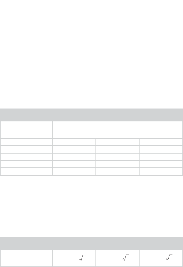
Recommended Safety Distances (Table 206)
• Safety distances help prevent interference if you
maintain a minimum distance between transmitters
such as mobile RF telecommunication devices and the
ICS 3000. The necessary distance depends on the
respective power output of the transmitter.
Note: At 80 MHz and at 800 MHz, the higher frequency range
applies.
• For transmitters whose maximum output power is not
indicated in the table, the recommended safety
distance d can be calculated in meters using an
equation that is suitable for the respective
transmission frequency range. P is the maximum
output power of the transmitter in watts [W] according
to the specification of the transmitter’s manufacturer.
Transmission
Frequency 150 kHz to 80 MHz 80 MHz up to
800 MHz 800 MHz to
2.5 GHz
Maximum output
power of the
transmitter [W]
Safety distance [m]
0,01 0,12 0,12 0,24
0,1 0,37 0,37 0,74
1 1,17 1,17 2,34
10 3,70 3,70 7,40
100 11,7 11,7 23,4
Transmission
Frequency 150 kHz to 80 MHz 80 MHz up to
800 MHz 800 MHz to
2.5 GHz
Equation
d117P,= d117P,= d234P,=

44 Electromagnetic Compatibility
Resistance to Electromagnetic Interference
(Tables 202 and 204)
• When the measured field strength exceeds the
specified compliance level at the operating location of
the ICS 3000, observe the device in order to determine
whether it is functioning properly.
• If abnormal performance is observed, additional
measures may be necessary, such as re-orienting or
relocating the device. In the frequency range of
150 kHz to 80 MHz, ensure that field strengths are
lower than 3 V/m.
Note: UT is the mains alternating voltage before applying the
test levels.
Test of Interference
Resistance
Test Level
According to
IEC 60601-1-2
Compliance Guidelines for the
Electromagnetic
Environment
Electrostatic discharge
(ESD)
According to
IEC 61000-4-2
±6 kV contact
discharge
±8 kV air
discharge
Same as test
level • Operate the devices on
floors made of wood,
concrete, or ceramic tile.
If the floor is covered with
synthetic material, the
relative humidity must be
at least 30%.
Fast transient electric
interference (bursts)
According to
IEC 61000-4-4
±2 kV for power
lines
±1 kV for input
and output lines
Same as test
level • Ensure that the power
supply quality is that of a
typical commercial and/
or hospital environment.
Surges
According to
IEC 61000-4-5
±1 kV push-pull
voltage
±2 kV push-
push voltage
Voltage drops, brief
interruptions, and
supply voltage
fluctuations
According to
IEC 61000-4-11
<5% UT for
1/2 period
>95% drop
40% UT for
5periods
60% drop
70% UT for
25 periods
30% drop
<5% UT for 5 s
>95% drop
Same as test
level • Ensure that the power
supply quality is that of a
typical commercial and/
or hospital environment.
• If you require continued
operation during power
supply interruptions,
connect the device to an
uninterruptible power
supply or use a battery
for operation.

45 Electromagnetic Compatibility
Note: At 80 MHz and at 800 MHz, the higher frequency range
applies.
Magnetic field at the
supply frequencies
(50/60 Hz)
According to
IEC 61000-4-8
3 A/m Same as test
level • Ensure that the magnetic
field strengths are at
levels characteristic of a
location in a typical
commercial and/or
hospital environment.
Test of Interference
Resistance Test Level
According to
IEC 60601-1-2
Compliance Guidelines for the
Electromagnetic
Environment
Test of Interference
Resistance Test Level
According to
IEC 60601-1-2
Compliance Guidelines for the
Electromagnetic
Environment
Conducted
RF interference
According to
IEC 61000-4-6
3V
eff 3 V • Maintain safety distance
of mobile radio equipment
to the ICS 3000; see
page 5
• The field strength of
stationary transmitting
devices must be
measured on site and
must be lower than the
compliance level at all
frequencies: consider any
studies done on site.
• The field strength must be
lower than 3 V/m over the
frequency range of
150 kHz to 80 MHz.
Radiated
RF interference
According to
IEC 61000-4-3
3V/m
80 MHz to
2.5 GHz
3V/m

46 Symbol Index
Symbol Index
Follow the instructions for use!
Operation Module
On/Off button
Button for displaying the battery level
Safe program button
Emergency shock button
ECG input with a BF degree of protection,
defibrillation-proof
Connection for the PGH 3000 programming head
with a B degree of protection
Programming Head
Safe program button on the PGH 3000 programming
head
Position indicator on the PGH 3000 programming head
47 Symbol Index
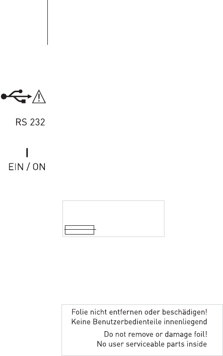
Docking Station
USB port, only for devices approved by BIOTRONIK
Serial port
ON switch, for switching on the system even when the
battery is fully depleted
Mains
Mains voltage; mains frequency; power consumption
Mains current for the fuse (surge-proof)
Housing covers Labeling on protective port covers:
100-115 V~; 60 Hz; 1.2 A
220-230 V~; 50 Hz; 0.6 A
3.51 A-T

48

49 Index
Index
AAccessories, optional ................................................ 40
Adhesive and clip electrodes, approved ...................40
Analog telemetry.......................................................31
BBluetooth interface ................................................... 22
CCalling up and triggering an emergency shock ....... 30
Calling up and triggering the safe program ............. 30
Care ........................................................................... 32
Carrying handle......................................................... 17
CD drive ..................................................................... 18
Changing a fuse.........................................................34
Charging circuit, technical data................................38
Cleaning and disinfection..........................................32
Connecting and disconnecting the
Operation Module................................................ 18
DData transfer ............................................................. 29
Disposal.....................................................................34
Docking Station ......................................................... 17
Docking Station, symbols.......................................... 47
Documentation..........................................................29
EECG electrodes, approved......................................... 40
ECG module, technical data...................................... 36
ECG recorder and ECG monitor ................................27
ECG, port on the Operation Module ..........................22
Electromagnetic compatibility .............................. 8, 42
Emergency programs................................................29
EMI test .....................................................................31
Environmental conditions .........................................35
Esophageal electrode, approved ECG electrodes..... 40
External defibrillation ...............................................10
External Printer ........................................................ 26
IICS 3000 PGH (Programming head).......................... 23
ICS 3000 SW Software...............................................27
Infrared, interface on the Operation Module ............ 22
Installing the technical manual CD ..........................27
Intended use................................................................4
Internal Printer .........................................................19
Interrogating and programming the implant ........... 29

50 Index
MMaintenance..............................................................33
Miniclinic ............................................................. 28, 37
NNon-invasive programmed stimulation....................31
OOperation Module......................................................21
Operation Module, symbols ......................................46
Operation Module, technical data .............................35
Overmodulation......................................................... 28
PPGH programming head ...........................................23
PGH programming head, technical data .................. 37
PGH with straight cable ............................................ 25
PGH, port on the Operation Module.......................... 22
Power supply, technical data ....................................38
Printer, external........................................................26
Printer, internal ........................................................38
Programmer..............................................................27
programming head, country-related information, ... 41
programming head, symbols ....................................46
RRechargeable battery, technical data.......................35
Recording ECGs and IEGMs ...................................... 28
SSafe program button .................................................24
Safety and maintenance inspections ........................33
safety and maintenance inspections ........................33
Safety distances, recommended............................... 43
Safety instructions ......................................................4
Scope of delivery .......................................................39
Screen ................................................................. 21, 36
Serial port .................................................................20
Sterilization ...............................................................33
Storage and shipping ................................................ 11
Switching off the system........................................... 14
Switching on the system ...........................................12
Symbols on the equipment .......................................46
TTechnical data ........................................................... 35
UUL certification..........................................................41
USB port on the Docking Station ..............................20
VVentilation slots................................................... 17, 21