BIOTRONIK SE and KG PNP Medical Implant Pacemaker User Manual eIFU en 417804 B Enticos ProMRI 2016 03 23
BIOTRONIK SE & Co. KG Medical Implant Pacemaker eIFU en 417804 B Enticos ProMRI 2016 03 23
Contents
- 1. 15a_UserMan_Enticos
- 2. 15b_UserMan_Enitra
- 3. 15c_UserMan_Evity
- 4. 15d_UserMan_Edora
15a_UserMan_Enticos
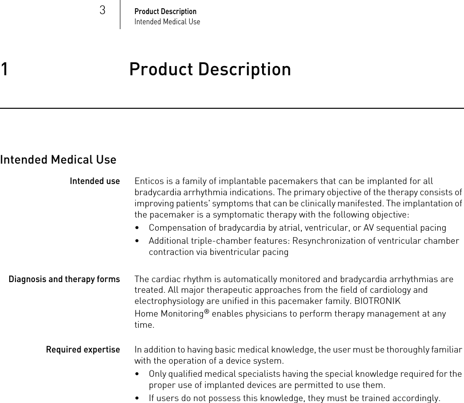
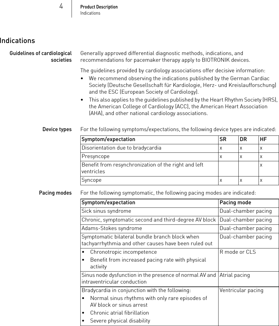
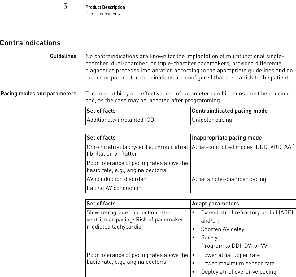
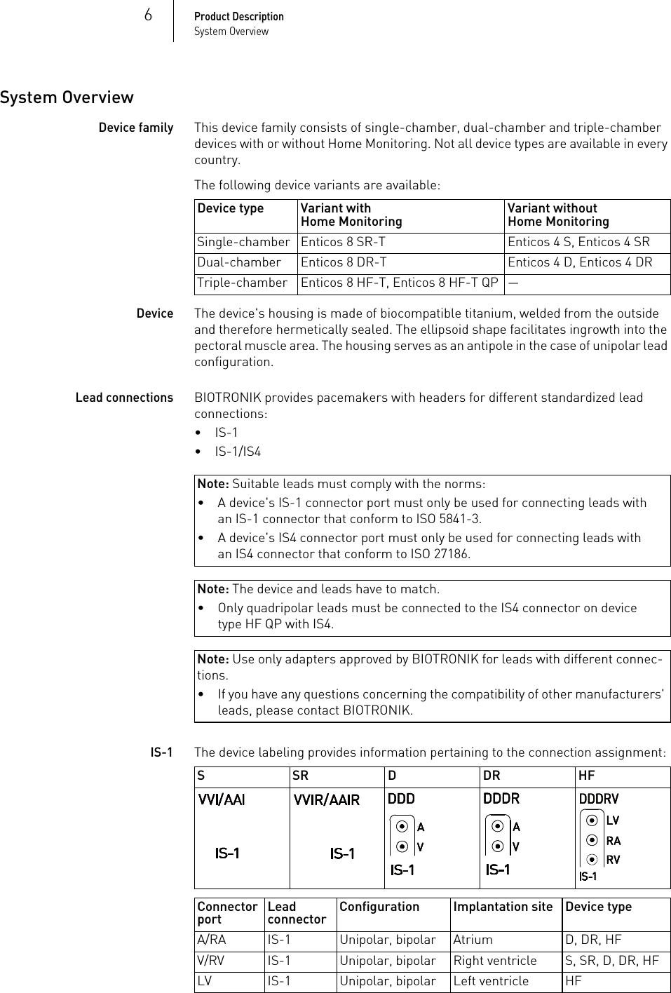
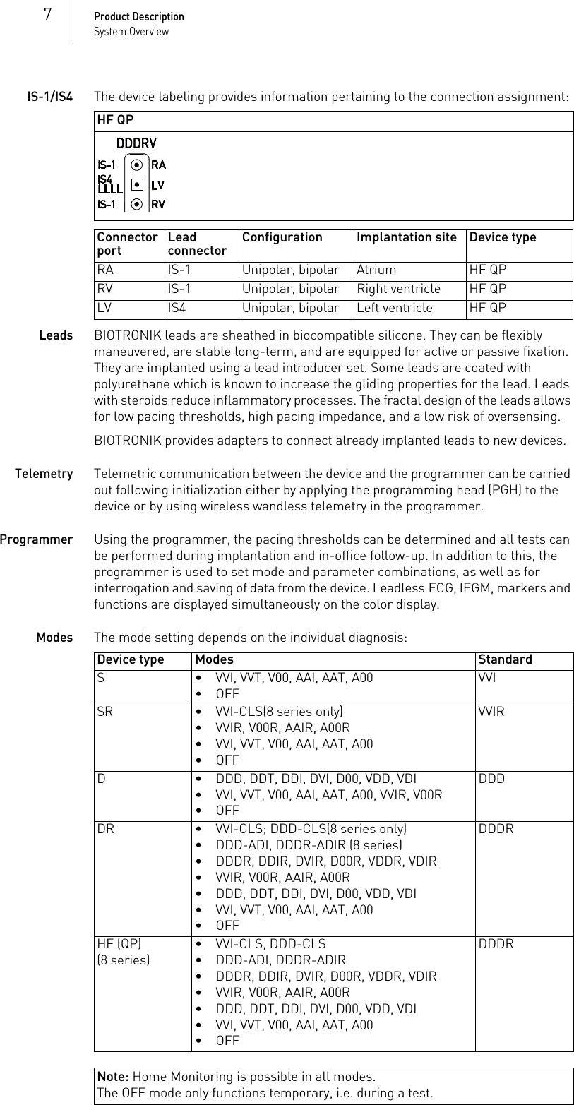
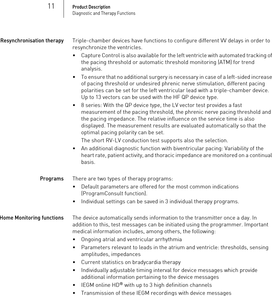
![36Technical DataMechanical Characteristics5 Technical DataTechnical Data5417804Technical ManualEnticos 4/8Note: D = housing without headerMechanical CharacteristicsMeasurements for the housingX-ray identificationAll device types receive the BIOTRONIK logo for X-ray identification. It can be found centrally between the circuitry and the battery.Materials in contact with body tissue• Housing: Titanium• Header: Epoxy, polysulfone; IS4 seal: Silastic• Silicone plug: Silopren or silasticDevice W x H x D [mm] Volume [cm3] Mass [g]Single-chamber S, SR(-T)48 x 40 x 6.5 10 20.8Dual-chamber D, DR(-T)48 x 44 x 6.5 11 23.2Triple-chamber HF-T 53 x 52 x 6.5 14 26.9Triple-chamber HF-T QP53 x 53 x 6.5 15 31.2](https://usermanual.wiki/BIOTRONIK-SE-and-KG/PNP.15a-UserMan-Enticos/User-Guide-2952983-Page-36.png)