BIOTRONIK SE and KG PNP Medical Implant Pacemaker User Manual eIFU en 417804 B Enticos ProMRI 2016 03 23
BIOTRONIK SE & Co. KG Medical Implant Pacemaker eIFU en 417804 B Enticos ProMRI 2016 03 23
Contents
- 1. 15a_UserMan_Enticos
- 2. 15b_UserMan_Enitra
- 3. 15c_UserMan_Evity
- 4. 15d_UserMan_Edora
15a_UserMan_Enticos

Enticos 4/8
Pacemaker | Bradyarrhythmia Therapy |
Cardiac Resynchronization Therapy
Technical Manual
417804
Revision: B (2016-03-23)
© BIOTRONIK SE & Co. KG
All rights reserved.
Specification subject to modification, revision and improvement.
® All product names in use may be trademarks or registered trademarks held
by BIOTRONIK or the respective owner.
Index 417804Technical ManualEnticos 4/8
0123 2016
BIOTRONIK SE & Co. KG
Woermannkehre 1
12359 Berlin · Germany
Tel +49 (0) 30 68905-0
Fax +49 (0) 30 6852804
sales@biotronik.com
www.biotronik.com

2
Table of Contents
Table of Contents
Table of Contents
Product Description . . . . . . . . . . . . . . . . . . . . . . . . . . . . . . . . . . . . . . . . . . . . . 3
Intended Medical Use. . . . . . . . . . . . . . . . . . . . . . . . . . . . . . . . . 3
Indications. . . . . . . . . . . . . . . . . . . . . . . . . . . . . . . . . . . . . . . . . . 4
Contraindications . . . . . . . . . . . . . . . . . . . . . . . . . . . . . . . . . . . . 5
System Overview. . . . . . . . . . . . . . . . . . . . . . . . . . . . . . . . . . . . . 6
Diagnostic and Therapy Functions . . . . . . . . . . . . . . . . . . . . . 10
General Safety Instructions. . . . . . . . . . . . . . . . . . . . . . . . . . . . . . . . . . . . . . 12
Operating Conditions . . . . . . . . . . . . . . . . . . . . . . . . . . . . . . . . 12
Possible Complications . . . . . . . . . . . . . . . . . . . . . . . . . . . . . . 13
Possible Risks. . . . . . . . . . . . . . . . . . . . . . . . . . . . . . . . . . . . . . 14
Implantation . . . . . . . . . . . . . . . . . . . . . . . . . . . . . . . . . . . . . . . . . . . . . . . . . . 15
Implantation Procedure . . . . . . . . . . . . . . . . . . . . . . . . . . . . . . 15
Precautionary Measures while Programming . . . . . . . . . . . . 18
Magnet Response . . . . . . . . . . . . . . . . . . . . . . . . . . . . . . . . . . . 21
Follow-up . . . . . . . . . . . . . . . . . . . . . . . . . . . . . . . . . . . . . . . . . 22
Patient Information. . . . . . . . . . . . . . . . . . . . . . . . . . . . . . . . . . 23
Replacement Indications . . . . . . . . . . . . . . . . . . . . . . . . . . . . . 24
Explantation and Device Replacement . . . . . . . . . . . . . . . . . . 26
Parameters . . . . . . . . . . . . . . . . . . . . . . . . . . . . . . . . . . . . . . . . . . . . . . . . . . . 27
Timing . . . . . . . . . . . . . . . . . . . . . . . . . . . . . . . . . . . . . . . . . . . . 27
Pacing and Sensing . . . . . . . . . . . . . . . . . . . . . . . . . . . . . . . . . 30
Rate Adaptation . . . . . . . . . . . . . . . . . . . . . . . . . . . . . . . . . . . . 32
Preset Programs . . . . . . . . . . . . . . . . . . . . . . . . . . . . . . . . . . . 33
Tolerances of Parameter Values. . . . . . . . . . . . . . . . . . . . . . . 35
Technical Data . . . . . . . . . . . . . . . . . . . . . . . . . . . . . . . . . . . . . . . . . . . . . . . . 36
Mechanical Characteristics . . . . . . . . . . . . . . . . . . . . . . . . . . . 36
Electrical Characteristics . . . . . . . . . . . . . . . . . . . . . . . . . . . . 37
Battery Data . . . . . . . . . . . . . . . . . . . . . . . . . . . . . . . . . . . . . . . 39
Legend for the Label . . . . . . . . . . . . . . . . . . . . . . . . . . . . . . . . 41

3
Product Description
Intended Medical Use
1 Product Description
Product Description1417804Technical ManualEnticos 4/ 8
Intended Medical Use
Intended use
Enticos is a family of implantable pacemakers that can be implanted for all
bradycardia arrhythmia indications. The primary objective of the therapy consists of
improving patients' symptoms that can be clinically manifested. The implantation of
the pacemaker is a symptomatic therapy with the following objective:
• Compensation of bradycardia by atrial, ventricular, or AV sequential pacing
• Additional triple-chamber features: Resynchronization of ventricular chamber
contraction via biventricular pacing
Diagnosis and therapy forms
The cardiac rhythm is automatically monitored and bradycardia arrhythmias are
treated. All major therapeutic approaches from the field of cardiology and
electrophysiology are unified in this pacemaker family. BIOTRONIK
Home Monitoring® enables physicians to perform therapy management at any
time.
Required expertise
In addition to having basic medical knowledge, the user must be thoroughly familiar
with the operation of a device system.
• Only qualified medical specialists having the special knowledge required for the
proper use of implanted devices are permitted to use them.
• If users do not possess this knowledge, they must be trained accordingly.

4
Product Description
Indications
Indications
Guidelines of cardiological
societies
Generally approved differential diagnostic methods, indications, and
recommendations for pacemaker therapy apply to BIOTRONIK devices.
The guidelines provided by cardiology associations offer decisive information:
• We recommend observing the indications published by the German Cardiac
Society (Deutsche Gesellschaft für Kardiologie, Herz- und Kreislaufforschung)
and the ESC (European Society of Cardiology).
• This also applies to the guidelines published by the Heart Rhythm Society (HRS),
the American College of Cardiology (ACC), the American Heart Association
(AHA), and other national cardiology associations.
Device types
For the following symptoms/expectations, the following device types are indicated:
Pacing modes
For the following symptomatic, the following pacing modes are indicated:
Symptom/expectation SR DR HF
Disorientation due to bradycardia x x x
Presyncope x x x
Benefit from resynchronization of the right and left
ventricles
x
Syncope xxx
Symptom/expectation Pacing mode
Sick sinus syndrome Dual-chamber pacing
Chronic, symptomatic second and third-degree AV block Dual-chamber pacing
Adams-Stokes syndrome Dual-chamber pacing
Symptomatic bilateral bundle branch block when
tachyarrhythmia and other causes have been ruled out
Dual-chamber pacing
• Chronotropic incompetence
• Benefit from increased pacing rate with physical
activity
R mode or CLS
Sinus node dysfunction in the presence of normal AV and
intraventricular conduction
Atrial pacing
Bradycardia in conjunction with the following:
• Normal sinus rhythms with only rare episodes of
AV block or sinus arrest
• Chronic atrial fibrillation
• Severe physical disability
Ventricular pacing

5
Product Description
Contraindications
Contraindications
Guidelines
No contraindications are known for the implantation of multifunctional single-
chamber, dual-chamber, or triple-chamber pacemakers, provided differential
diagnostics precedes implantation according to the appropriate guidelines and no
modes or parameter combinations are configured that pose a risk to the patient.
Pacing modes and parameters
The compatibility and effectiveness of parameter combinations must be checked
and, as the case may be, adapted after programming.
Set of facts Contraindicated pacing mode
Additionally implanted ICD Unipolar pacing
Set of facts Inappropriate pacing mode
Chronic atrial tachycardia, chronic atrial
fibrillation or flutter
Atrial-controlled modes (DDD, VDD, AAI)
Poor tolerance of pacing rates above the
basic rate, e.g., angina pectoris
AV conduction disorder Atrial single-chamber pacing
Failing AV conduction
Set of facts Adapt parameters
Slow retrograde conduction after
ventricular pacing: Risk of pacemaker-
mediated tachycardia
• Extend atrial refractory period (ARP)
and/or:
• Shorten AV delay
• Rarely:
Program to DDI, DVI or VVI
Poor tolerance of pacing rates above the
basic rate, e.g., angina pectoris
• Lower atrial upper rate
• Lower maximum sensor rate
• Deploy atrial overdrive pacing
6
Product Description
System Overview
System Overview
Device family
This device family consists of single-chamber, dual-chamber and triple-chamber
devices with or without Home Monitoring. Not all device types are available in every
country.
The following device variants are available:
Device
The device's housing is made of biocompatible titanium, welded from the outside
and therefore hermetically sealed. The ellipsoid shape facilitates ingrowth into the
pectoral muscle area. The housing serves as an antipole in the case of unipolar lead
configuration.
Lead connections
BIOTRONIK provides pacemakers with headers for different standardized lead
connections:
•IS-1
•IS-1/IS4
Note: Suitable leads must comply with the norms:
Note: The device and leads have to match.
Note: Use only adapters approved by BIOTRONIK for leads with different connec-
tions.
IS-1
The device labeling provides information pertaining to the connection assignment:
Device type Variant with
Home Monitoring Variant without
Home Monitoring
Single-chamber Enticos 8 SR-T Enticos 4 S, Enticos 4 SR
Dual-chamber Enticos 8 DR-T Enticos 4 D, Enticos 4 DR
Triple-chamber Enticos 8 HF-T, Enticos 8 HF-T QP —
• A device's IS-1 connector port must only be used for connecting leads with
an IS-1 connector that conform to ISO 5841-3.
• A device's IS4 connector port must only be used for connecting leads with
an IS4 connector that conform to ISO 27186.
• Only quadripolar leads must be connected to the IS4 connector on device
type HF QP with IS4.
• If you have any questions concerning the compatibility of other manufacturers'
leads, please contact BIOTRONIK.
SSRDDRHF
Connector
port Lead
connector Configuration Implantation site Device type
A/RA IS-1 Unipolar, bipolar Atrium D, DR, HF
V/RV IS-1 Unipolar, bipolar Right ventricle S, SR, D, DR, HF
LV IS-1 Unipolar, bipolar Left ventricle HF

Note: Home Monitoring is possible in all modes.
The OFF mode only functions temporary, i.e. during a test.
7
Product Description
System Overview
IS-1/IS4
The device labeling provides information pertaining to the connection assignment:
Leads
BIOTRONIK leads are sheathed in biocompatible silicone. They can be flexibly
maneuvered, are stable long-term, and are equipped for active or passive fixation.
They are implanted using a lead introducer set. Some leads are coated with
polyurethane which is known to increase the gliding properties for the lead. Leads
with steroids reduce inflammatory processes. The fractal design of the leads allows
for low pacing thresholds, high pacing impedance, and a low risk of oversensing.
BIOTRONIK provides adapters to connect already implanted leads to new devices.
Telemetry
Telemetric communication between the device and the programmer can be carried
out following initialization either by applying the programming head (PGH) to the
device or by using wireless wandless telemetry in the programmer.
Programmer
Using the programmer, the pacing thresholds can be determined and all tests can
be performed during implantation and in-office follow-up. In addition to this, the
programmer is used to set mode and parameter combinations, as well as for
interrogation and saving of data from the device. Leadless ECG, IEGM, markers and
functions are displayed simultaneously on the color display.
Modes
The mode setting depends on the individual diagnosis:
HF QP
Connector
port Lead
connector Configuration Implantation site Device type
RA IS-1 Unipolar, bipolar Atrium HF QP
RV IS-1 Unipolar, bipolar Right ventricle HF QP
LV IS4 Unipolar, bipolar Left ventricle HF QP
Device type Modes Standard
S • VVI, VVT, V00, AAI, AAT, A00
•OFF
VVI
SR • VVI-CLS(8 series only)
• VVIR, V00R, AAIR, A00R
• VVI, VVT, V00, AAI, AAT, A00
•OFF
VVIR
D • DDD, DDT, DDI, DVI, D00, VDD, VDI
• VVI, VVT, V00, AAI, AAT, A00, VVIR, V00R
•OFF
DDD
DR • VVI-CLS; DDD-CLS(8 series only)
• DDD-ADI, DDDR-ADIR (8 series)
• DDDR, DDIR, DVIR, D00R, VDDR, VDIR
• VVIR, V00R, AAIR, A00R
• DDD, DDT, DDI, DVI, D00, VDD, VDI
• VVI, VVT, V00, AAI, AAT, A00
•OFF
DDDR
HF (QP)
(8 series)
• VVI-CLS, DDD-CLS
• DDD-ADI, DDDR-ADIR
• DDDR, DDIR, DVIR, D00R, VDDR, VDIR
• VVIR, V00R, AAIR, A00R
• DDD, DDT, DDI, DVI, D00, VDD, VDI
• VVI, VVT, V00, AAI, AAT, A00
•OFF
DDDR

8
Product Description
System Overview
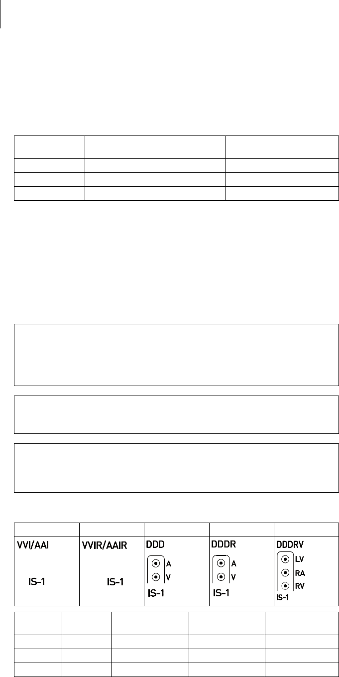
NBG codes
AAI or VVI is the NBG code for the antibradycardia mode of the single-chamber
device without rate adaptation (device type S and D); AAIR or VVIR is the NBG code
for the antibradycardia mode of the single-chamber device with rate adaptation
(device type SR and DR):
DDDR is the NBG code for the antibradycardia mode of the dual-chamber device:
DDDRV is the NBG code for the antibradycardia mode of the triple-chamber device:
BIOTRONIK Home Monitoring
®In addition to effective pacing therapy, BIOTRONIK provides a complete therapy
management system:
• With Home Monitoring, diagnostic and therapeutic information and technical
data are automatically sent to a stationary or mobile transmitter via an antenna
in the device header. The data are encrypted and sent from the transmitter to
the BIOTRONIK Service Center via the cellular phone network.
• The received data are deciphered and evaluated. Each physician can set the
criteria for evaluation to be used for each patient and can configure the time of
notification via e-mail, SMS or fax.
• A clear overview of the results of this analysis is displayed for the attending
physicians on the protected internet platform Home Monitoring Service Center
(HMSC).
• Data transmission from the device is performed with a daily device message.
• Device messages, which indicate special events in the patient's heart or in the
device, are forwarded with the following message.
• A test message can be initiated at any time using the programmer to
immediately check the Home Monitoring function.
Order numbers for Enticos
The devices can be obtained as follows:
A/V Pacing in the atrium or ventricle
A/V Sensing in the atrium or ventricle
I Pulse inhibition in the atrium and ventricle
R Rate adaptation
D Pacing in the atrium and ventricle
D Sensing in the atrium and ventricle
D Pulse inhibition and pulse triggering
R Rate adaptation
D Pacing in the atrium and ventricle
D Sensing in the atrium and ventricle
D Pulse inhibition and pulse triggering
R Rate adaptation
V Multisite pacing in both ventricles
Enticos 4 S 407168 Enticos 8 SR-T 407160
Enticos 4 SR 407167 Enticos 8 DR-T 407148
Enticos 4 D 407156 Enticos 8 HF-T 407144
Enticos 4 DR 407155 Enticos 8 HF-T QP 407143

9
Product Description
System Overview
Package contents
The storage package includes the following:
• Sterile packaging with device
• Serial number label
• Patient ID card
• Warranty booklet
Note: The technical manual pertaining to the device is either included in hard copy
form in the storage package or in digital form on the internet.
The sterile packaging includes the following:
•Device
• Screwdriver

10
Product Description
Diagnostic and Therapy Functions
Diagnostic and Therapy Functions
General overview
All the systems have extensive features that allow quick diagnosis and delivery of
safe therapy for bradycardia conditions.
• Automatic functions make it easy and fast to implant, configure, and check the
pacemaker.
• Auto-initialization after implantation: The device recognizes the implanted leads
autonomously and sets the polarity. The automatic functions of the software are
activated after 10 min.
Diagnostics functions
• For devices from the 8 series: Data from the last interrogations and follow-ups
are recorded as well as arrhythmia episodes; they are stored together with
other data to assess the state of both the patient and the device at any time.
• Continuous automatic below-threshold impedance measurements are
performed in the device independent of the pacing pulse in order to check the
lead for proper functioning.
• Once a telemetry connection has been established during a test procedure in an
in-office follow-up, the IEGM is displayed with markers.
Antibradycardia pacing
• Sensing: The amplitudes of the P and R waves are measured in the implanted
device fully automatically and permanently to record varying amplitudes. The
sensitivity for the atrium and ventricle is adapted automatically on an ongoing
basis. The measurement data are averaged and the trend can be displayed.
• Pacing thresholds: Pacing thresholds are automatically identified in the device,
in single and dual-chamber devices the right ventricular, in triple-chamber
devices the right and left ventricular pacing thresholds. Capture control adjusts
the pulse amplitudes in such a way that every change of the pacing threshold
results in the patient being paced at an optimal amplitude.
• Timing: Pacing in the atrium is checked particularly carefully in dual and triple-
chamber devices by an automatic adaptation of the atrial refractory period in
order to avoid pacemaker-mediated tachycardia (Auto PVARP function: the
postventricular atrial refractory period is adapted automatically).
• Additional, special form of rate adaptation with devices from the 8 series:
An increased cardiac output requirement is detected using physiological
impedance measurement. The measuring principle is based on contractile
changes (ionotropy) of the myocardium (CLS function: Closed Loop Stimulation).
Rate adaptation is automatically initialized and optimized in CLS mode.
• Ventricular pacing suppression with devices from the 8 series: Unnecessary
ventricular pacing is avoided by promoting intrinsic conduction (Vp suppression
function). The device can adapt itself to conduction changes. In the case of
intrinsic conduction, the device switches from a DDD(R) to an ADI(R) mode.
• 8 series: In the course of the follow-up, an automatic test of the AV delay is
performed to improve the heart performance. AV delays are calculated; the
optimum values can be applied.

11
Product Description
Diagnostic and Therapy Functions
Resynchronisation therapy
Triple-chamber devices have functions to configure different VV delays in order to
resynchronize the ventricles.
• Capture Control is also available for the left ventricle with automated tracking of
the pacing threshold or automatic threshold monitoring (ATM) for trend
analysis.
• To ensure that no additional surgery is necessary in case of a left-sided increase
of pacing threshold or undesired phrenic nerve stimulation, different pacing
polarities can be set for the left ventricular lead with a triple-chamber device.
Up to 13 vectors can be used with the HF QP device type.
• 8 series: With the QP device type, the LV vector test provides a fast
measurement of the pacing threshold, the phrenic nerve pacing threshold and
the pacing impedance. The relative influence on the service time is also
displayed. The measurement results are evaluated automatically so that the
optimal pacing polarity can be set.
The short RV-LV conduction test supports also the selection.
• An additional diagnostic function with biventricular pacing: Variability of the
heart rate, patient activity, and thoracic impedance are monitored on a continual
basis.
Programs
There are two types of therapy programs:
• Default parameters are offered for the most common indications
(ProgramConsult function).
• Individual settings can be saved in 3 individual therapy programs.
Home Monitoring functions
The device automatically sends information to the transmitter once a day. In
addition to this, test messages can be initiated using the programmer. Important
medical information includes, among others, the following:
• Ongoing atrial and ventricular arrhythmia
• Parameters relevant to leads in the atrium and ventricle: thresholds, sensing
amplitudes, impedances
• Current statistics on bradycardia therapy
• Individually adjustable timing interval for device messages which provide
additional information pertaining to the device messages
• IEGM online HD® with up to 3 high definition channels
• Transmission of these IEGM recordings with device messages

12
General Safety Instructions
Operating Conditions
2 General Safety Instructions
General Safety Instructions2417804Technical ManualEnticos 4/8
!
!
CAUTION
Safety information
Cardiac electrotherapy is subject to special operating conditions and possible
complications and risks.
Operating Conditions
Technical manuals
The following technical manuals provide information about usage of the device
systems:
— Technical manual for the device
— Technical manual for the HMSC
— Technical manuals for leads
— Technical manuals for the programmer and its accessories
— Technical manuals for the user interface
— Technical manuals for cables, adapters and accessories
• Technical manuals are either included in hard copy form in the storage package
or in digital form on the internet:
manuals.biotronik.com
• Follow all relevant technical manuals.
• Keep technical manuals for later use.
Care during shipping and
storage
• Devices are not to be stored close to magnets or sources of electromagnetic
interference.
• Note the effects of the storage period; see Battery Data.
Temperature
Extremely low and high temperatures affect the service time of the battery in the
device.
• Permitted for shipping and storage:
–10°C to +45°C
Sterile delivery
The device and the screwdriver have been gas-sterilized. Sterility is guaranteed only
if the blister and quality control seal have not been damaged.
Sterile packaging
The device and screwdriver are each packaged in 2 separately sealed blisters. The
inner blister is also sterile on the outside so that it can be transferred in a sterile
state during implantation.
Single use only
The device and screwdriver are intended for single use only.
• Do not use the device if the package is damaged.
• The device must not be resterilized and reused.
• Please take all precautionary measures carefully into account.

13
General Safety Instructions
Possible Complications
Possible Complications
General information on
medical complications
Complications for patients and device systems generally recognized among
practitioners also apply to BIOTRONIK devices.
• Normal complications may include fluid accumulation within the device pocket,
infections, or tissue reactions. Primary sources of complication information
include current scientific and technological knowledge.
• It is not possible to guarantee the efficacy of antiarrythmia therapy, even if the
programs have proven successful during tests or subsequent
electrophysiological examinations. In rare cases the set parameters can
become ineffective. In particular it is inevitable that tachyarrhythmias may be
induced.
Skeletal myopotentials
Bipolar sensing and control of sensitivity are adapted by the device to the rate range
of intrinsic events so that skeletal myopotentials are usually not sensed. Skeletal
myopotentials can nonetheless be classified as intrinsic events especially with a
unipolar configuration and/or very high sensitivity and, depending on the
interference, may cause inhibition or antiarrhythmia therapy.
Nerve and muscle stimulation
A device system consisting of a unipolar lead and an uncoated device may result in
undesirable pacing of the diaphragm in the case of an initial or permanent high
setting of the pulse amplitude.
Possible technical failures
Technical failure of a device system cannot be entirely ruled out. Possible causes
may include the following:
• Lead dislodgement
• Lead fracture
• Insulation defects
• Device component failures
• Battery depletion
Electromagnetic interference
(EMI)
Any device can be sensitive to interference, for example, when external signals are
sensed as intrinsic rhythm.
• BIOTRONIK devices have been designed so that their susceptibility to EMI is
minimal.
• Due to the intensity and variety of EMI, there is no guarantee for safety. It is
generally assumed that EMI produces only minor symptoms in patients - if any.
• Depending on the pacing mode and the type of interference, sources of
interference may lead to pulse inhibition or triggering, an increase in the
sensor-dependent pacing rate or asynchronous pacing.
• Under unfavorable conditions, for example during diagnostic or therapeutic
procedures, interference sources may induce such a high level of energy into
the pacing system that the cardiac tissue surrounding the lead tip is damaged.
Device behavior in case of EMI
In the case of electromagnetic interference or undesired myopotentials, the device
paces asynchronously for the duration of the time that the interference rate is
exceeded.
Static magnetic fields
The pacemaker switches to magnet response from a field strength > 1.0 mT.

14
General Safety Instructions
Possible Risks
Possible Risks
Procedures to avoid
The following procedures must be avoided as they may cause harm to the patient or
damage the device and, as a result, put the system functionality at risk:
• Therapeutic ultrasound
• Transcutaneous electrical nerve stimulation
• Hyperbaric oxygen therapy
• Applied pressures higher than normal pressure
Potentially risky therapeutic
and diagnostic procedures
If electrical current from an external source is conducted through the body for
diagnostic or therapeutic purposes, then the device can be subjected to
interference and the patient placed at risk.
Arrhythmia or ventricular fibrillation can be induced during diathermic procedures
such as electrocautery, HF ablation or HF surgery. For example, damaging
pressure levels may arise during lithotripsy. Influences on the device are not always
immediately clear.
If potentially risky procedures cannot be avoided, the following should be observed
at all times:
• Electrically insulate patients.
• Switch the pacemaker function to asynchronous modes if needed.
• Do not introduce energy near the device system.
• Check the peripheral pulse of the patient.
• Monitor the patient during and after every intervention.
External defibrillation
The device is protected against the energy that is normally induced by external
defibrillation. Nevertheless, any implanted device may be damaged by external
defibrillation. Specifically, the current induced in the implanted leads may result in
necrotic tissue formation close to the electrode/tissue interface. As a result,
sensing properties and pacing thresholds may change.
• Place adhesive electrodes anterior-posterior or perpendicular to the axis
formed by the device to the heart at least 10 cm away from the device and from
implanted leads.
Radiation therapy
The use of radiation therapy must be avoided due to possible damage to the device
and the resulting impaired functional safety. If this type of therapy is to be used
anyway, prior risk/benefit analysis is absolutely necessary. The complexity of
influencing factors such as different sources of radiation, a variety of devices and
therapy conditions makes it impossible to issue directives that guarantee radiation
therapy without an impact on the device. The EN 45502 standard pertaining to active
implantable medical devices requires the following measures during the
administration of therapeutic ionizing radiation:
• Adhere to instructions for potentially risky therapeutic and diagnostic
procedures.
• Shield device against radiation.
• After applying radiation, double-check the device system to make sure it is
functioning properly.
Note: Please contact BIOTRONIK with questions on the risk/benefit analysis.
Magnetic resonance imaging
Magnetic resonance imaging must be avoided due to the associated high frequency
fields and magnetic flux density: Damage or destruction of the device system by
strong magnetic interaction and damage to the patient by excessive warming of the
body tissue in the area surrounding the device system.

15
Implantation
Implantation Procedure
3 Implantation
Implantation3417804Technical ManualEnt icos 4/8
Implantation Procedure
Having parts ready
The following parts that correspond to the requirements of the
EC Directive 90/385/EEC are required:
• Device with screwdriver from BIOTRONIK
• BIOTRONIK leads and lead introducer set
— Single-chamber device: unipolar or bipolar lead for the right ventricle
— Dual-chamber device: one unipolar or bipolar lead each for the atrium and
for the right ventricle
— Triple-chamber device: an additional unipolar, bipolar, or quadripolar
LV lead
• Approved connections are IS-1 and IS4: Use only adapters approved by
BIOTRONIK for leads with different connections or leads from other
manufacturers.
• BIOTRONIK programmer (with integrated wandless telemetry or with separate
SafeSync Module) and approved cables
• External multi-channel ECG device
• Keep spare parts for all sterile components.
Keeping an external
defibrillator ready
In order to be able to respond to unforeseeable emergencies or possible technical
failures of the device:
• Keep an external defibrillator and paddles or adhesive electrodes ready.
!
!
WARNING
Inadequate therapy due to defective device
If an unpacked device is dropped on a hard surface during handling, electronic
parts could be damaged.
Unpacking the device
• Peel the sealing paper off of the outer blister at the marked position in the
direction indicated by the arrow. The inner blister must not come into contact
with persons who have not sterilized their hands or gloves, nor with non-sterile
instruments.
• Use the gripping tab on the inner blister to remove it from the outer blister.
• Peel the sealing paper off of the sterile inner blister at the marked position in
the direction indicated by the arrow.
Note: The device is disabled on delivery and can be implanted immediately after
unpacking without manual activation.
Checking parts
Damage to any of the parts can result in complications or technical failures.
• Check for damage before and after unpacking all parts.
• Replace damaged parts.
• Use a replacement device.
• Return the damaged device to BIOTRONIK.
Note: If necessary, the device can also be programmed before or during auto-
initialization.
16
Implantation
Implantation Procedure
Implantation site
In general, the pacemaker is implanted subcutaneously or subpectorally,
depending on the lead configuration as well as the anatomy of the patient.
Overview: Implanting
Avoid damage to the header
Set screws must be tightened or loosened with care.
• Loosen set screws with the supplied screwdriver. Use only BIOTRONIK
screwdrivers with torque control!
• If lead revision is necessary, re-order sterile screwdrivers from BIOTRONIK.
!
!
WARNING
Short circuit due to open lead connector ports
Connector ports in the header which are open and thus not electrolyte-proof may
cause undesired current flows to the body and penetration of body fluid into the
device.
!
!
WARNING
Inadequate therapy
Insufficient lead spacing or inappropriate lead positioning may lead to far-field
sensing.
Preventing short circuits
in the header
Keeping distance
between leads
1 Shape the device pocket and prepare the vein.
2 Implant the leads and perform measurements.
3 Connect device and leads.
4 Insert the device.
The device starts auto-initialization on its own.
5 Guide the fixation suture through the opening in the header and fixate the
device in the prepared device pocket.
6 Close the device pocket.
7 Prior to testing and configuration, wait for the successful completion of
automatic device initialization.
• Close unused connector ports with blind plugs.
• Leads must not contact each other. Position the tip and ring of newly implanted
leads with a sufficient distance from old implanted leads.

17
Implantation
Implantation Procedure
Connecting the lead connector
to the device
Applying the programming
head
The programming head (PGH) features a diagram of the device. This is used to
assist in positioning the head to ensure proper telemetry.
• Make sure the PGH is positioned correctly.
Establishing wandless
telemetry
For devices from the 8 series: The programmer must be no less than 20 cm and no
more than 3 m from the device; ideally there should be no hindrances between the
patient and the programmer.
• Switch on wandless telemetry on the programmer.
• Apply the programming head for about 2 s until successful initialization is
displayed on the programmer:
The wandless telemetry symbol is displayed in the navigator and the
signal strength is displayed in the status line.
• Remove the programming head.
Note: After auto-initialization, all parameters are activated as in the standard
program.
Auto-initialization
Auto-initialization begins automatically once the first connected lead is sensed.
Auto-initialization is usually terminated 10 minutes after connection of the first
lead. If no other program has been transferred in the meantime, the device
subsequently works with active automatic functions in the factory settings or with
the preset program of the user.
Manual setting of the lead polarity or measurement of lead impedances is not
necessary.
Behavior during auto-
initialization
• During transmission of a permanent program:
Auto-initialization is terminated and the transferred program is active.
• During testing:
Tests cannot be performed during auto-initialization; stop it beforehand.
Auto-initialization will not be continued upon completion of the test.
1 Remove stylets and stylet guides.
2 • Connect the unipolar or bipolar IS-1 lead connector for the right ventricle
to RV.
• Connect the unipolar or bipolar IS-1 lead connector atrium to A.
• Connect the unipolar or bipolar IS-1 or the quadripolar IS4 lead connector
for the left ventricle to LV.
3 Push the lead connector into the header without bending the conductor until
the connector tip becomes visible behind the set screw block.
4 If the lead connector cannot be inserted completely, the set screw may be
protruding into the drill hole of the set screw block. Carefully loosen the set
screw without completely unscrewing it, so that it does not become tilted
upon retightening.
5 Use the screwdriver to perpendicularly pierce through the slitting in the
center of the silicone plug until it reaches the set screw.
6 Turn the set screw clockwise until the torque control starts (you will hear a
clicking sound).
7 Carefully withdraw the screwdriver without retracting the set screw.
• When the screwdriver is withdrawn, the silicone plug automatically seals
the lead connection safely.

18
Implantation
Precautionary Measures while Programming
Precautionary Measures while Programming
!
!
CAUTION
Safety information
The programming of device systems requires special precautions.
Checking the device system
• After auto-initialization, perform a follow-up to see if the device system is
functioning properly.
• Perform a pacing threshold test to determine the pacing threshold.
Performing standard tests and
monitoring the patient
Critical conditions can occur for the patient even during standard tests due to
inadequate parameter settings or interrupted telemetry.
• Ensure sufficient patient care even during tests.
• After the threshold test, check to determine whether the threshold is clinically
and technically justifiable.
• Continuously monitor the ECG and the patient's condition.
• Cancel testing if necessary.
Do not interrupt wandless
telemetry during a treatment
Disconnecting the SafeSync Module from the programmer can result in
interference with or termination of the SafeSync wandless telemetry.
• Do not disconnect the SafeSync Module from the programmer.
• Do not take the Operation Module off the ICS 3000.
Cancelling telemetry
Programmer interference or interrupted telemetry during performance of
temporary programs (follow-up tests) can result in inadequate pacing of the
patient. This is the case if the programmer can no longer be operated due to a
program error or a defective touch screen and therefore the temporary program
cannot be terminated. Under these circumstances, it is helpful to cancel telemetry,
in which case the device automatically switches to the permanent program.
• In the case of telemetry with PGH: lift the programming head by at least 30 cm.
• In the case of wandless telemetry: switch off and reposition the programmer.
• Turn off possible sources of interference.
Avoiding critical parameter
settings
No modes and parameter combinations that pose a risk to the patient should be set.
• Prior to setting rate adaptation, determine the patient's capacity for strain.
• Check compatibility and effectiveness of parameter combinations after making
settings.
Manually setting lead polarity
Due to the risk of an entrance/exit block, bipolar lead polarity (sensing/pacing)
should only be set if bipolar leads are implanted.
Setting sensing
Manually set parameters can be unsafe. For example, unsuitable far-field
protection may impede sensing of intrinsic pulses.
• Use automatic sensitivity control.
Setting the sensitivity
A value set to < 2.5 mV/unipolar for device sensitivity may result in noise caused by
electromagnetic fields.
• Therefore, it is recommended that a value of ≥ 2.5 mV/unipolar be set according
to paragraph 28.22.1 of the EN 45502-2-1 standard. Setting sensitivity values
< 2.5 mV/unipolar requires explicit clinical need. Values like this must only be
set and retained with physician supervision.
• Please carefully take all precautionary measures into account.

19
Implantation
Precautionary Measures while Programming
Preventing device-induced
complications
BIOTRONIK devices are equipped with several functions to prevent device-induced
complications to the greatest extent possible:
• Measure the retrograde conduction time.
• If the function is not yet automatically set: activate PMT protection.
• Set the VA criterion: The aim is to set a VA criterion that is longer than the
longest measured retrograde conduction time.
Preventing conduction of atrial
tachycardia
BIOTRONIK devices are equipped with several functions to prevent conduction of
atrial tachycardia to the ventricle(s):
•Set Mode Switching for indicated patients.
• Set the upper rate and the refractory periods to prevent abrupt ventricular rate
switching.
• Prefer Wenckebach response and avoid 2:1 behavior.
• Set all parameters so as to prevent constant changing between atrial and
ventricular-controlled modes.
Phrenic nerve stimulation that
cannot be terminated
With LV pacing, chronic phrenic nerve stimulation can in rare cases not be
terminated by reprogramming the available left ventricular pacing configurations
or by other measures.
• Possibly set a right ventricular mode both in the permanent program and for
Mode Switching.
Avoiding risks in the case of
exclusive left ventricular
pacing
Lead dislodgement in the case of exclusive left ventricular pacing could pose the
following risks: loss of ventricular pacing as well as induction of atrial arrhythmia.
• Consider sensing and pacing parameters with reference to loss of therapy.
• Exclusive left ventricular pacing is not recommended for patients who depend
on the device.
• Take possible interruption of automatic Active Capture Control into
consideration.
• In the case of follow-ups and threshold tests, take loss of synchronized
ventricular pacing into consideration.
• Mode Switching does not allow exclusive left ventricular pacing; consider the
consequences when setting Mode Switching parameters.
If an ICD is implanted at the
same time, do not permit
unipolar pacing
If an ICD is implanted in addition to a pacemaker and a lead failure occurs, it is
possible to switch to unipolar pacing after resetting the pacemaker or using the
automatic lead check. As a result, the ICD could falsely inhibit or trigger
tachyarrhythmiatherapy activity.
• Unipolar leads are not permitted in this configuration.
Recognizing lead failure
Automatic impedance measurement is always switched on.
• Impedance values that indicate technical failure of a lead are documented in the
event list.

20
Implantation
Precautionary Measures while Programming
Consider power consumption
and service time
The pacemaker permits programming of high pulse amplitudes with long pulse
widths at high rates to be able to adequately treat even rare diagnoses. In
combination with low lead impedance, this results in a very high level of power
consumption.
• When programming large parameter values, take into account that the
replacement indication ERI will be reached very early because the service time
of the battery may be reduced to less than 1 year.
Home Monitoring: The CardioMessenger should be relatively close to the patient;
if it is too far away, the device constantly seeks and consumes more power than
necessary.
• Home Monitoring ON reduces the service time by approximately 15% in single-
and dual-chamber devices and by approximately 10% in triple-chamber devices.
Wandless telemetry: 15 minutes of usage reduces the service time by
approximately 7 days.
• Do not establish unnecessary wandless telemetry.
•After 5 min without input, the device switches to the economy mode.
• Check the battery capacity of the device at regular intervals.

21
Implantation
Magnet Response
Magnet Response
Programming head application
When the programming head is applied, time remains for device interrogation
before the device switches back to the previously set permanent therapy mode. The
same applies to programming head application to establish wandless telemetry
contact.
Magnet response in standard
program
Applying a magnet or the programming head can result in an unphysiological
rhythm change and asynchronous pacing. The magnet response is set as follows in
the standard program of BIOTRONIK pacemakers:
• Asynchronous:
For the duration of the magnet application – mode D00 (where applicable
V00 / A00) without rate adaptation;
Magnet rate: 90 bpm
•Automatic:
For 10 cycles – mode D00, subsequently mode DDI without rate adaptation;
Magnet rate: 10 cycles with 90 bpm, subsequently set basic rate
• Synchronous:
Note: See also the replacement indication information for magnet response at ERI.
Mode DDD (where applicable: VVI) without rate adaptation;
Magnet rate: set basic rate
Magnet application by patients
If patients are performing their own magnet application, the synchronous magnet
response must have been programmed. Patients should also know the following:
• When may the magnet be used?
In cases of severe dizziness and indisposition.
• How long is the magnet placed on the pacemaker?
1 to 2 s.
• What happens when the magnet is applied?
The IEGM of the last 10 seconds is stored.
• What has to happen after magnet application?
The patient has to contact the physician for a follow-up.

22
Implantation
Follow-up
Follow-up
Follow-up intervals
Follow-ups must be performed at regular, agreed intervals.
• Following the lead ingrowth phase, approximately 3 months after implantation,
the first follow-up should be carried out by the physician using the programmer
(in-office follow-up).
• The next in-office follow-up should be carried out once a year and no later than
12 months after the last in-office follow-up.
Follow-up with BIOTRONIK
Home Monitoring
®
Monitoring using the Home Monitoring function does not serve to replace regular
in-office appointments with the physician required for other medical reasons.
Follow-up supported by Home Monitoring can be used to functionally replace in-
office follow-up under the following conditions:
• The patient was informed that the physician must be contacted if symptoms
worsen or if new symptoms arise despite the use of the Home Monitoring
function.
• Device messages are transmitted regularly.
• The physician decides whether the data transmitted via Home Monitoring with
regard to the patient's clinical condition as well as the technical state of the
device system are sufficient. If not, an in-office follow-up has to be carried out.
Possible early detection due to information gained via Home Monitoring may
necessitate an additional in-office follow-up. For example, the data may indicate at
an early stage lead problems or a foreseeable end of service time (ERI).
Furthermore, the data could provide indications of previously unrecognized
arrhythmias or regarding modification of therapy by reprogramming the device.
Follow-up with the
programmer
Use the following procedure for in-house follow-up:
1 Record and evaluate the ECG.
2 Interrogate the device.
3 Evaluate the status and automatically measured follow-up data.
4 Check the sensing and pacing functions.
5 Manually perform standard tests if necessary.
6 Possibly evaluate statistics and IEGM recordings.
7 Possibly adjust program functions and parameters.
8 Transmit the program permanently to the device.
9 Print and document follow-up data (print report).
10 Finish the follow-up for this patient.

23
Implantation
Patient Information
Patient Information
Patient ID card
A patient ID card is included in delivery.
• Provide the patient with the patient ID card.
• Request that patients contact the physician in case of uncertainties.
Prohibitive signs
Premises with prohibitive signs must be avoided.
• Draw the patient's attention to prohibitory signs.
Possible sources of
interference
Electromagnetic interference should be avoided in daily activities. Sources of
interference should not be brought into close proximity of the device.
• Draw the patient's attention to special household appliances, security
checkpoints, anti-theft alarm systems, strong electromagnetic fields, cellular
phones, and transmitters among other things.
• Request patients to do the following:
— Use cellular phones on the opposite side of their body from the device.
— Keep the cellular phone at least 15 cm away from the device both during use
and when stowing.

24
Implantation
Replacement Indications
Replacement Indications
Possible charging status
The time span from the beginning of service (BOS) to elective replacement
indication (ERI) is determined by, among others, the following:
• Battery capacity
• Lead impedance
• Pacing program
• Pacing to inhibition ratio
• Pacemaker circuit properties
The following are the defined pacemaker operational statuses:
• BOS: Beginning of Service: > 90%
• ERI: Elective Replacement Indication (i.e., RRT: Recommended Replacement
Time)
• EOS: End of Service
ERI activation
ERI detection is automatically activated after the following events:
• Successful auto-initialization
ERI display
ERI is displayed as follows:
• On the programmer after interrogation of the pacemaker
• By a defined decrease in the basic rate as well as the magnet rate
Rate decrease
The decrease of basic rate and magnet rate is defined as follows:
• In the following modes, the pacing rate decreases by 11%:
DDD(R); DDT; D00(R); VDD(R); VDI(R); VVI(R); VVT; AAI(R); AAT; A00(R)
• In the modes DDI(R) and DVI(R), only the VA interval is extended by 11%. This
reduces the pacing rate by up to 11%, depending on the configured AV delay.
Change of the mode with ERI
This change depends on the mode which is set. It is displayed on the programmer.
• Single-chamber modes: VVI
• Dual-chamber modes: VDD
• Triple-chamber modes: Dual-chamber pacing, one biventricular setting is kept
Deactivated functions with ERI
The following functions are deactivated:
• Atrial pacing
• Night program
• Rate adaptation
• Atrial and ventricular capture control
• Rate fading
• Atrial overdrive pacing
• IEGM recordings
• Statistics
• Home Monitoring
• Rate hysteresis
• Ventricular pacing suppression

25
Implantation
Replacement Indications
Magnet response at ERI
After reaching ERI, pacing is performed as follows after applying the magnet or
programming head:
Expected service times
after ERI
The information is based on the following:
• Lead impedance of 500 Ω or 600 Ω
• 100% pacing
• Interval from ERI to EOS for the single-chamber device in AAI(R)/VVI(R) mode,
for the dual and triple-chamber device in DDD(R) mode
• Standard program with both high and low pacing energy
• Data of the battery manufacturer (see the battery data)
Magnet
response Cycles 1 to 10 After 10th cycle
Automatic Asynchronous with 80 bpm Synchronous with basic rate
reduced by 11%
Asynchronous Asynchronous with 80 bpm Asynchronous with 80 bpm
Synchronous Synchronous with basic rate
reduced by 11%
Synchronous with basic rate
reduced by 11%
110 bpm
4.6 V
1.5 ms
500 Ω
30 bpm
0.2 V
0.1 ms
500 Ω
70 bpm
2.5 V
0.4 ms
500 Ω
70 bpm
5.0 V
0.4 ms
500 Ω
60 bpm
2.5 V
0.4 ms
600 Ω
60 bpm
5 V
0.4 ms
600 Ω
Mean value: 8 months
Minimum value: 6 months
—
Minimum value: 6 months
—
Minimum value: 6 months

26
Implantation
Explantation and Device Replacement
Explantation and Device Replacement
Explantation
• Disconnect the leads from the header.
• Remove the device and, if necessary, leads using state-of-the-art technology.
• Explants are biologically contaminated and must be disposed of safely due to
risk of infection.
Device replacement
The following applies to leads from a previous device that are intended for further
use:
• Check the leads prior to connecting to the new device.
If, upon replacing the device, already implanted leads are no longer used but left in
the patient, then an additional uncontrolled current path to the heart can result.
• Isolate unused lead connectors and close unused connector ports.
Basic principles:
• The device must not be resterilized and reused.
Cremation
Devices should not be cremated.
• Explant the device before the cremation of a deceased patient.
Disposal
BIOTRONIK takes back used products for the purpose of environmentally safe
disposal.
• Clean the explant with a solution of at least 1% sodium hypochlorite.
• Rinse with water.
• Fill out explantation form and send to BIOTRONIK together with the cleaned
device.

27
Parameters
Timing
4 Parameters
Parameters4417804Technical ManualEnticos 4/8
Note: Unless described separately, information for device type HF also applies to
device type HF QP.
Timing
Basic rate day/night
Rate hystereses
AV delay
AV hystereses
Parameter Range of values Standard SR DR HF
Basic rate 30 ... (5) ... 100 ... (10)
... 200 bpm
60 bpm x x
50 bpm x
Night rate OFF; 30 ... (5) ... 100 ... (10)
... 200 bpm
OFF x x x
Night begins 00:00 ... (10 min) ...
23:50 hh:mm
—xxx
Night ends
Parameter Range of values Standard SR DR HF
Hysteresis OFF; -5 ... (-5) ... -25 ... (-20)
... -65 bpm
OFF x x x
Repetitive/ search
cycles
OFF; ON OFF x x x
Parameter Range of values Standard SR DR HF
AV delay Low; Medium; High; Fixed;
Individual
Low x x
20 ... (5) ... 350 ms
(in 6 rate ranges)
180-170-
160-150-
140 ms
x
CLS and all HF modes:
20 ... (5) ... 350 ms
(in 6 rate ranges)
150-140-
130-120-
120 ms
xx
Sense compensation OFF; -10 ... (-5) ... -120 ms -45 ms x x
Parameter Range of values Standard SR DR HF
AV hysteresis mode OFF; Positive; Negative
HF when setting RV: IRSplus
OFF x x
Positive modes: AV
hysteresis
70; 110; 150; 200 ms 70 ms
CLS modes:
110 ms
xx
Negative modes: AV
hysteresis
10 ... (10) ... 150 ms 50 ms x x
AV repetetive / scan
cyles
OFF; ON ON x x

28
Parameters
Timing
Ventricular pacing
Upper rate
Mode switching
Ventricular pacing
suppression
Parameters valid for devices in DDD-ADI or DDDR-ADIR modes:
Parameter Range of values Standard SR DR HF
Ventricular pacing BiV, RV; LV BiV x
Triggering OFF; RVs; RVs + PVC RVs x
LV T-wave protection ON; OFF ON x
Maximum trigger rate AUTO; 90 ... (10) ... 160 bpm AUTO x
Initially paced
chamber
RV; LV LV x
VV delay after Vp 0 ... (5) ... 80 ... (10) ... 100 ms 0 ms x
VV delay after Vs 0 ms 0 ms x
Parameter Range of values Standard SR DR HF
Upper rate
SR: in VVT mode
90 ... (10) ... 200 bpm 130 bpm x x x
Wenckebach response/
2:1 rate
Automatically set — x x
Atrial upper rate OFF; 175; 200; 240 bpm 240 bpm x x
Parameter Range of values Standard SR DR HF
Mode switching OFF; ON ON x x
Intervention rate 100 ... (10) ... 250 bpm 160 bpm x x
Switch to mode DDI; DDI(R) when
permanent DDD(R)
VDI; VDI(R) when
permanent VDD(R)
DDI(R) x x
Ventricular pacing RV; BiV BiV x
Onset criterion 3 ... (1) ... 8 (out of 8) 5 x x
Resolution criterion x x
Change of the basic rate
with mode switching
OFF; +5 ... (5) ... +30 bpm +10 bpm
Rate stabilization with
mode switching
OFF; ON OFF x x
2:1 lock-in protection OFF; ON ON x
When setting RV: OFF;
ON
ON x
Parameter Range of values Standard SR DR HF
Vp suppression OFF; ON OFF x x
Pacing suppression after
consecutive Vs
1 ... (1) ... 8 6 x x
Pacing support after x cycles 1 ... (1) ... 4 (out of 8) 3 x x

29
Parameters
Timing
Refractory periods
Blanking periods
PMT protection
Parameter Range of values Standard SR DR HF
RV refractory period 200 ... (25) ... 500 ms 250 ms x x x
Atrial refractory
period
AUTO AUTO x x
Atrial refractory
period in the modes
AAI(R); AAT(R); DDT
300 ... (25) ... 775 ms 350 ms x x
LV refractory period 200 ms 200 ms x
AUTO PVARP OFF; ON ON x x
PVARP 175 ... (25) ... 600 ms 225 ms x x
PVARP after PVC PVARP + 150 ms
(max: 600 ms)
Automatically set x x
Parameter Range of values Standard SR DR HF
Far-field protection
after Vs
100 ... (10) ... 220 ms 100 ms x x
Far-field protection
after Vp
100 ... (10) ... 220 ms 150 ms x x
Ventricular blanking
period after Ap
30 ... (5) ... 70 ms 30 ms x x
Parameter Range of values Standard SR DR HF
PMT protection OFF; ON ON x x
VA criterion 250 ... (25) ... 500 ms 350 ms x x

30
Parameters
Pacing and Sensing
Pacing and Sensing
Pulse amplitude and
pulse width
Sensitivity
Atrial capture control
Ventricular capture control
Atrial overdrive pacing
Parameter Range of values Standard SR DR HF
Pulse
amplitude A/RV/LV
0.2 ... (0.2) ... 6.0 ... (0.5)
... 7.5 V
3.0 V x x x
Pulse width A/RV/LV 0.1 ...(0.1) ... 0.5 ... (0.25)
... 1.5 ms
0.4 ms x x x
Parameter Range of values Standard SR DR HF
Sensitivity AUTO; 0.5 ... (0.5) ... 7.5 mV AUTO x
Sensitivity A AUTO; 0.1 ... (0.1) ... 1.5 ...
(0.5) ... 7.5 mV
AUTO x x
RV sensitivity AUTO; 0.5 ... (0.5) ... 7.5 mV AUTO x x x
LV sensitivity OFF; AUTO; 0.5 ... (0.5) ...
7.5 mV
AUTO x
Parameter Range of values Standard SR DR HF
Atrial capture control ATM (monitoring only); ON;
OFF
ON x x
Minimum amplitude 0.5 ... (0.1) ... 4.8 V 1.0 V x x
Threshold test start 2.4 ... (0.6) ... 4.8 V 3.0 V x x
Safety margin 0.5 ... (0.1) ... 1.2 V 1.0 V x x
Search type Interval; time of day Time of day x x
Interval 0.1; 0.3; 1; 3; 6; 12; 24 h 24 h x x
Time of day 00:00 ... (00:10) ...
23:50 hh:mm
00:30 hh:mm x x
Parameter Range of values Standard SR DR HF
Capture control RV ATM (monitoring only); ON;
OFF
ON x x x
Capture control LV x
Minimum
amplitude RV
0.7 V 0.7 V x x x
Minimum
amplitude LV
x
Threshold test start 2.4 ... (0.6) ... 4.8 V 3.0 V x x x
RV safety margin 0.3 ... (0.1) ... 1.2 V 0.5 V x x
LV safety margin 1.0; 1.2 V 1.0 V x
Search type Interval; time of day Time of day x x x
Interval 0.1; 0.3; 1; 3; 6; 12; 24 h 24 h x x x
Time of day 00:00 ... (00:10)
... 23:50 hh:mm
00:30 hh:mm x x x
Parameter Range of values Standard SR DR HF
Atrial overdrive
pacing
OFF; ON
With ON: maximum over-
pacing rate 120 bpm, mean
rate increase approximately
8 bpm, rate decrease after
20 cycles
OFF x x

31
Parameters
Pacing and Sensing
Lead configuration
IEGM recordings
Rates for statistics
Parameter Range of values Standard SR DR HF
Sensing polarity A Unipolar; bipolar Unipolar x x x
Sensing polarity RV Unipolar; bipolar Unipolar x x x
Sensing polarity LV Unipolar; bipolar Unipolar x
Pacing polarity A Unipolar; bipolar Unipolar x x x
Pacing polarity RV Unipolar; bipolar Unipolar x x x
Pacing polarity LV Device type HF:
LV1 tip -> LV2 ring
LV1 tip -> RV ring
LV2 ring -> LV1 tip
LV2 ring -> RV ring
LV1 tip -> housing
LV2 ring -> housing
LV1 tip –>
housing
x
Device type HF QP
LV1 tip -> LV2 ring
LV1 tip -> LV4 ring
LV1 tip -> RV ring
LV1 tip -> housing
LV2 ring -> LV1 tip
LV2 ring -> LV4 ring
LV2 ring -> RV ring
LV2 ring -> housing
LV3 ring -> LV2 ring
LV3 ring -> LV4 ring
LV3 ring -> RV ring
LV4 ring -> LV2 ring
LV4 ring -> RV ring
LV1 tip –>
LV2 ring
x
Parameter Range of values Standard SR DR HF
Number of recordings
(each max. 10 s)
4 series: 4
12
8 series: 20
—xxx
High atrial rate (HAR) OFF; AT; mode switching AT x x x
High ventricular rate
(HVR)
OFF; ON ON x x x
8 series:
Patient triggering
(triggered by patient)
OFF; ON OFF x x x
Pre-trigger recording 0; 25; 50; 75; 100% 75% x x x
IEGM signal Filtered; Unfiltered Filtered x x x
Parameter Range of values Standard SR DR HF
HAR limit 100 ... (10) ... 250 bpm 200 bpm x x
HVR limit 150 ... (5) ... 200 bpm 180 bpm x x x
HVR counter 4; 8; 12; 16 events 8 events x x x
Start resting period 00:00 ... (1:00 AM) ...
23:00 hh:mm
2:00 hh:mm x x x
Duration of resting
period
0.5 ... (0.5) ... 12 h 4 h x x x
Enable lead check OFF; ON ON x x x

32
Parameters
Rate Adaptation
Rate Adaptation
CLS modes: closed loop
stimulation
Parameters valid for 8 series devices:
R modes: Accelerometer
Parameters valid for devices with R modes:
Parameter Range of values Standard SR DR HF
Maximum CLS rate 80 ... (10) ... 160 bpm 120 bpm x x x
CLS response Very low; Low; Medium;
High; Very high
Medium x x x
CLS resting rate
control
OFF; +10 ... (10) ... +50 bpm +20 bpm x x x
Vp required Yes; No No
When BiV is
set: Yes
xxx
Parameter Range of values Standard SR DR HF
Sensor gain AUTO; Very low; Low;
Medium; High; Very high
AUTO x x x
Max. activity rate 80 ... (10) ... 180 bpm 120 bpm x x x
Sensor threshold Very low; Low; Medium;
High; Very high
Medium x x x
Rate fading OFF; ON OFF x x x
Rate increase 1; 2; 4; 8 bpm/cycle 2 bpm/cycle x x x
Rate decrease 0.1; 0.2; 0.5; 1.0 bpm/cycle 0.5
bpm/cycle
xxx

33
Parameters
Preset Programs
Preset Programs
Standard and safe program
Mode after auto-initialization:
Lead configuration, determined and set immediately after connection (auto lead
check)
Parameters after auto-initialization:
Parameter Factory
setting Standard Safe program SR DR HF
Mode VVI VVIR VVI
In the AAI mode, the
safe program is also
AAI.
x
Mode DDD DDDR VVI x x
Parameter Factory
setting Standard Safe
program SR DR HF
Pacing polarity A/RV Unipolar Unipolar Unipolar x x x
Pacing polarity LV TCUP TCUP TCUP x
Sensing polarity A/RV Unipolar Unipolar Unipolar x x x
Sensing polarity LV Unipolar Unipolar Unipolar x
Automatic lead check ON ON — x x x
Parameter Factory
setting Standard Safe
program SR DR HF
Basic rate 60 bpm 60 bpm 70 bpm x x
50 bpm 50 bpm x
Night rate OFF OFF OFF x x x
Rate hysteresis OFF OFF OFF x x x
Upper rate 130 bpm 130 bpm — x x
AV dynamics Low Low — x x
AV hysteresis mode OFF OFF — x x
Sense compensation -45 ms -45 ms — x x
AV safety delay 100 ms 100 ms — x x
VV delay 0 0 0 x
LV T-wave protection ON ON ON x
Far-field protection after Vs 100 ms 100 ms — x x
Far-field protection after Vp 150 ms 150 ms — x x
Ventricular blanking period
after Ap
30 ms 30 ms — x x
PMT protection ONON— xx
VA criterion 350 ms 350 ms — x x
Magnet response AUTO AUTO AUTO x x x
Pulse amplitude A 3.0 V 3.0 V — x x
Pulse amplitude RV 3.0 V 3.0 V 4.8 V x x x
Pulse amplitude LV 3.0 V 3.0 V 4.8 V x
Pulse width A 0.4 ms 0.4 ms — x x
Pulse width RV 0.4 ms 0.4 ms 1.0 ms x x x
Pulse width LV 0.4 ms 0.4 ms 1.0 ms x
Sensitivity A AUTO AUTO — x x
Sensitivity RV AUTO AUTO 2.5 mV x x x
Sensitivity LV AUTO AUTO 2.5 mV x

34
Parameters
Preset Programs
Refractory period A AUTO AUTO — x x
Refractory period RV 250 ms 250 ms 300 ms x x x
Refractory period LV 200 ms 200 ms 200 ms x
Mode switching ON ON — x x
Onset criterion 5-out-of 8 5-out-of 8 — x x
Resolution criterion 5-out-of 8 5-out-of 8 — x x
Intervention rate 160 bpm 160 bpm — x x
Switches to DDIR DDIR — x x
The basic rate with mode
switching
+10 bpm +10 bpm — x x
Rate stabilization with
mode switching
OFF OFF — x x
PVARP AUTO (Start
250 ms)
225 ms) — x x
PVARP after PVC 400 ms Automati-
cally set
—xx
Capture control A ON ON OFF x x x
Capture control RV ON ON OFF x x
Capture control LV ON ON OFF x
Atrial overdrive pacing OFF OFF — x x
Vp suppression OFF OFF — x
IEGM recording (HAR) ON AT OFF x x x
IEGM recording (HVR) ON ON OFF x x x
Home Monitoring OFF OFF OFF x x x
Parameter Factory
setting Standard Safe
program SR DR HF

35
Parameters
Tolerances of Parameter Values
Tolerances of Parameter Values
Parameter Range of values Tolerance
Basic rate 30 ... (5) ... 100 ... (10)
... 200 bpm
± 20 ms
Basic interval 1000 ms ± 20 ms
Magnet rate (magnet interval) 90 bpm (664 ms) ± 20 ms
Pulse amplitude 0.2 ... 7.5 V The greater value of ±50 mV
or +20/-25%
Pulse width 0.1 ... 1.5 ms ±10%
Sensitivity A
EN 45502-2-1 triangle pulse
0.1 ... 0.2 mV ±0,05 mV
0.3 ... 7.5 mV ±20%
Sensitivity RV/LV
EN 45502-2-1 triangle pulse
0.5 ... 7.5 mV ±20%
Refractory period 200 ... 500 ms ± 20 ms
Maximum activity rate 80 ... 180 bpm ± 20 ms
Lead impedance 100 ... 200 Ω ±50 Ω
201 ... 2500 Ω ±10%
36
Technical Data
Mechanical Characteristics
5 Technical Data
Technical Data5417804Technical ManualEnticos 4/8
Note: D = housing without header
Mechanical Characteristics
Measurements for the housing
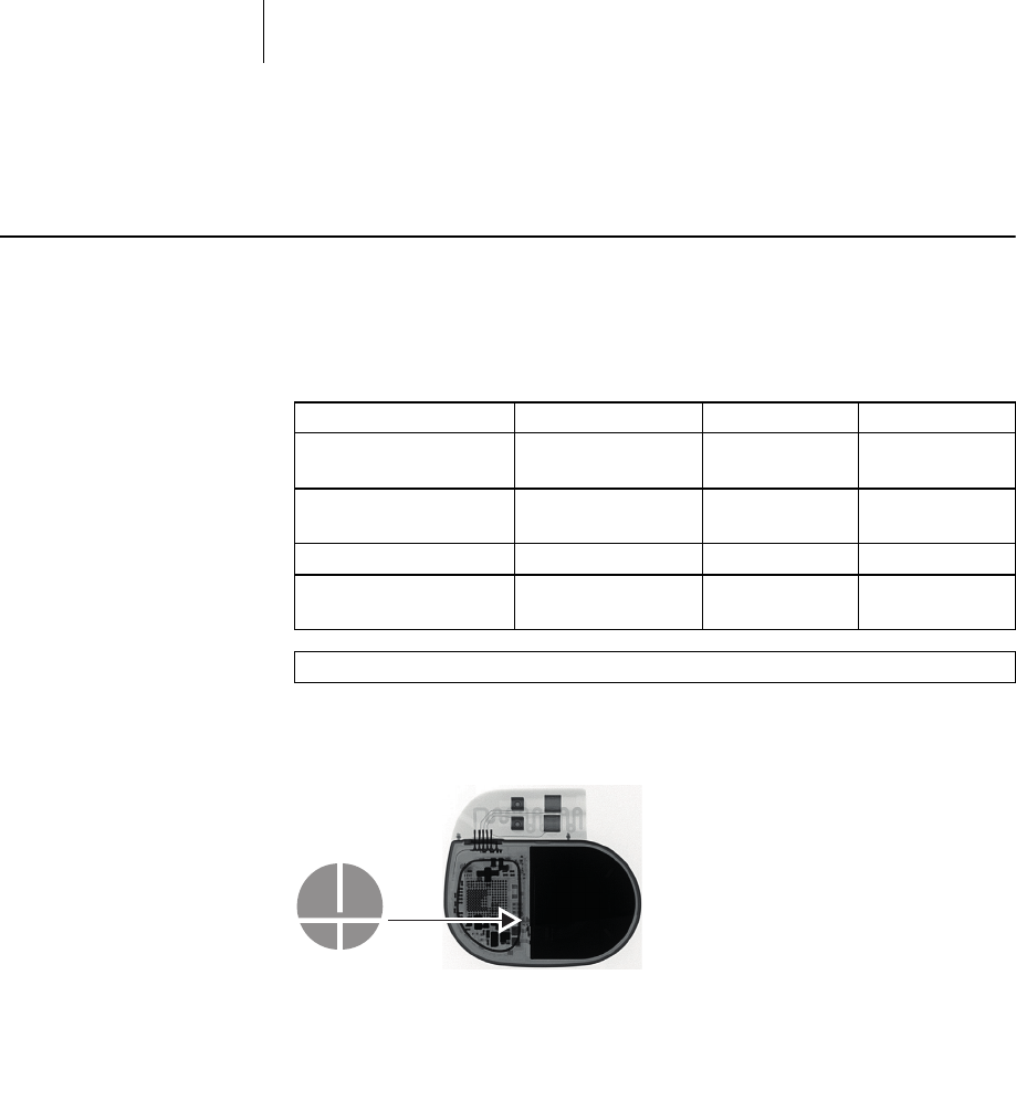
X-ray identification
All device types receive the BIOTRONIK logo for X-ray identification. It can be found
centrally between the circuitry and the battery.
Materials in contact with
body tissue
• Housing: Titanium
• Header: Epoxy, polysulfone; IS4 seal: Silastic
• Silicone plug: Silopren or silastic
Device W x H x D [mm] Volume [cm3] Mass [g]
Single-chamber
S, SR(-T)
48 x 40 x 6.5 10 20.8
Dual-chamber
D, DR(-T)
48 x 44 x 6.5 11 23.2
Triple-chamber HF-T 53 x 52 x 6.5 14 26.9
Triple-chamber
HF-T QP
53 x 53 x 6.5 15 31.2

37
Technical Data
Electrical Characteristics
Electrical Characteristics
Components and input values
Electrical characteristics determined at 37°C, 500 Ω:
Electrically conductive surface
The device housing has the form of a flattened ellipsoid. The electrically conductive
area is for:
• Single and dual-chamber devices: 30 cm2
• Triple-chamber devices: 33 cm2
Telemetry data
• MICS frequency: 402 - 405 MHz
• Maximum power of transmission: < 25 µW (-16 dBm)
International radio
certification
Devices with BIOTRONIK Home Monitoring® are equipped with an antenna for
wireless communication.
• Telemetry information for Australia:
This product is in compliance with the Australian
"Radiocommuniations Act 1992" and therefore it is labelled according to
the "Radiocommunications (Compliance Labelling - Devices) Notice."
• Telemetry information for Canada:
This device must neither interfere with meteorological and earth resources
technology satellites nor with meteorological stations working in the 400,150 to
406,000 MHZ band, and it must accept any interference received, including
interference that may cause undesired operation.
This device will be registered with Industry Canada under the following number:
IC: 4708A-PNP
The code IC in front of the certification/registration number only indicates that
the technical requirements for Industry Canada are met.
• Telemetry information for Japan:
In accordance with Japanese law, this device has been assigned an
identification number under the "Ordinance concerning certification of
conformity with technical regulations etc. of specified radio equipment",
Article 2-1-8.
R 202-LSE015
• Telemetry information for the USA:
Telemetry data for the USA: This transmitter is authorized by rule under the
Medical Device Radiocommunication Service (in part 95 of the FCC Rules) and
must not cause harmful interference to stations operating in the 400.150-
406.000 MHz band in the Meteorological Aids (i.e., transmitters and receivers
used to communicate weather data), the Meteorological Satellite, or the Earth
Exploration Satellite Services and must accept interference that may be caused
by such stations, including interference that may cause undesired operation.
This transmitter shall be used only in accordance with the FCC Rules governing
the Medical Device Radiocommunication Service. Analog and digital voice
communications are prohibited. Although this transmitter has been approved by
the Federal Communications Commission, there is no guarantee that it will not
receive interference or that any particular transmission from this transmitter
will be free from interference.
This device will be registered with Federal Communications Commission under
the following number:
FCC ID: QRIPNP
Circuit technology Dycostrate
Input impedance > 10 kΩ
Pulse form Biphasic, asymmetric
Polarity Cathodic
38
Technical Data
Electrical Characteristics
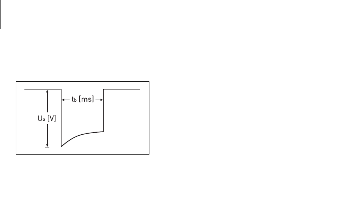
Pulse form
The pacing pulse has the following form:
The pulse amplitude reaches its maximum
value at the beginning of the pulse (Ua). With
increasing pacing duration (tb), the pulse
amplitude is reduced dependent on the pacing
impedance.
Resistance to interference
All variants of BIOTRONIK devices comply with the requirements of
EN 45502-2-1: 2003, § 27.5.1 at the highest sensitivity.

39
Technical Data
Battery Data
Battery Data
Battery characteristics
The following data is provided by the manufacturers:
Shortening of the service time
after long storage period
In case of implantation after an average storage period – about 1 year before the
end of the use by date – the average service time decreases by about 1%.
Power consumption
• BOS, inhibited: SR(-T), DR(-T) 6 µA; HF-T (QP) 7 µA
• BOS, 100% pacing: SR(-T) 8 µA; DR(-T) 11 µA; HF-T (QP) 14 µA
Calculation of service times
Mean service times pre-estimated from the following and other data:
• Storage for 6 months
• Technical data of the battery manufacturer
• Basic rate of 60 bpm in AAIR/VVIR modes (single-chamber devices) or DDDR
modes (dual-chamber and triple-chamber devices)
•Home Monitoring configuration: OFF
• No wandless telemetry
• Configuration of different pulse amplitudes and lead impedances
Mean service times S, SR
For single-chamber devices of the 4 series the following times result when set to
AAI(R) or VVI(R), with a basic rate of 60 bpm and a pulse width of 0.4 ms at an
impedance of 500 Ω:
For single-chamber devices of the 8 series the following times result when set to
AAI(R) or VVI(R), with a basic rate of 60 bpm and a pulse width of 0.4 ms at an
impedance of 500 Ω:
Manufacturer Wilson GREATBATCH,
INC. Clarence, NY 14031 LITRONIK GmbH,
01796 Pirna, Germany
Battery type GB 3395 LiS 2650 LiS 3150MK
System Li-Iodine Li-Iodine LiMn02
Device type S; SR; D; DR S; SR; D; DR HF; HF QP
Battery voltage at BOS 2.8 V 2.8 V 3.1 V
Open-circuit voltage 2.8 V 2.8 V 3.1 V
Nominal capacity 960 mAh 960 mAh 1200 mAh
Usable capacity until EOS 905 mAh 905 mAh 1066 Ah
Remaining capacity at ERI 55 mAh 55 mAh 134 mAh
Amplitude Pacing Average service time
2.5 V 100% 14 years
50% 16 years, 10 months
3.0 V 100% 12 years
50% 14 years, 10 months
5.0 V 100% 4 years, 7 months
Amplitude Pacing Average service time
2.5 V 100% 13 years
50% 14 years, 9 months
3.0 V 100% 11 years, 3 months
50% 13 years, 7 months
5.0 V 100 % 5 years, 6 months

40
Technical Data
Battery Data
Mean service times D, DR
For dual-chamber devices of the 4 series the following times result when set to
DDD(R), with a basic rate of 60 bpm and a pulse width of 0.4 ms at an impedance of
500 Ω:
For dual-chamber devices of the 8 series the following times result when set to
DDD(R), with a basic rate of 60 bpm and a pulse width of 0.4 ms at an impedance of
500 Ω:
Mean service times HF
For triple-chamber devices of the 8 series the following times result when set to
DDDR with a basic rate of 60 bpm, 100% biventricular pacing and a pulse width of
0.4 ms at an impedance of 500 Ω:
Amplitude Pacing Average service time
A: 2.5 V
RV: 2.5 V
100% 9 years, 10 months
50% 12 years, 4 months
A: 3.0 V
RV: 3.0 V
100% 7 years, 11 months
50% 10 years, 8 months
A: 5.0 V
RV: 5.0 V
100% 8 years, 1 months
Amplitude Pacing Average service time
A: 2.5 V
RV: 2.5 V
100% 9 years, 4 months
50% 11 years, 4 months
A: 3.0 V
RV: 3.0 V
100% 7 years, 8 months
50% 10 years
A: 5.0 V
RV: 5.0 V
100% 3 years, 2 months
Amplitude Pacing Average service time
A: 2.5 V 10% 9 years, 8 months
RV: 2.5 V
LV: 2.5 V
100%
A: 3.0 V 10 % 8 years
RV: 3.0 V
LV: 3.0 V
100%
A: 5.0 V
RV: 5.0 V
LV: 5.0 V
100% 2 years, 6 months
41
Technical Data
Legend for the Label
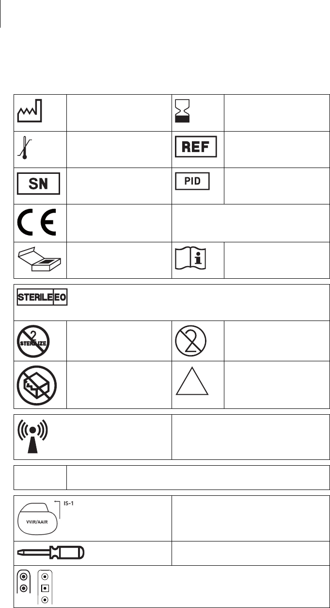
Legend for the Label
The label icons symbolize the following:
Manufacturing date Use by
Storage temperature Order number
Serial number Product identification
number
CE mark
Contents Follow the instructions for
use
Sterilized with ethylene oxide
Do not resterilize Single use only.
Do not re-use!
Do not use if packaging is
damaged
Non-sterile
Transmitter with non-ionizing radiation
at designated frequency
TP2 Compabiltiy with telemetry protocol version 2
of BIOTRONIK Home Monitoring
Example
Uncoated device: NBG code and
compatible leads
Screwdriver
Examples of the connector allocation: IS-1, IS-1/IS4
NON
STERILE