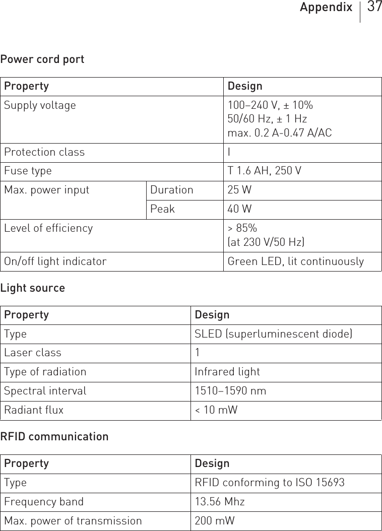
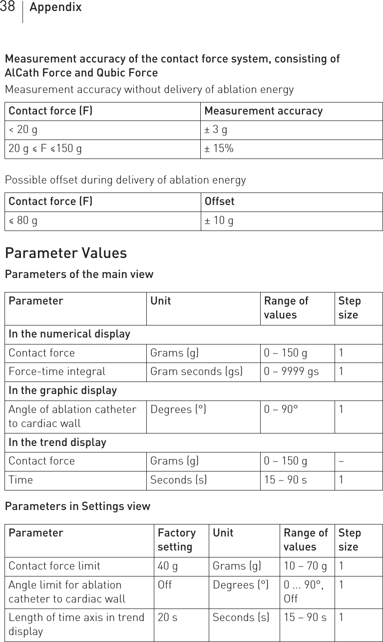
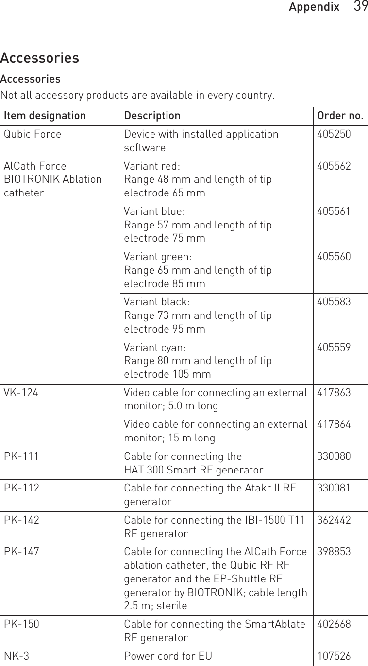
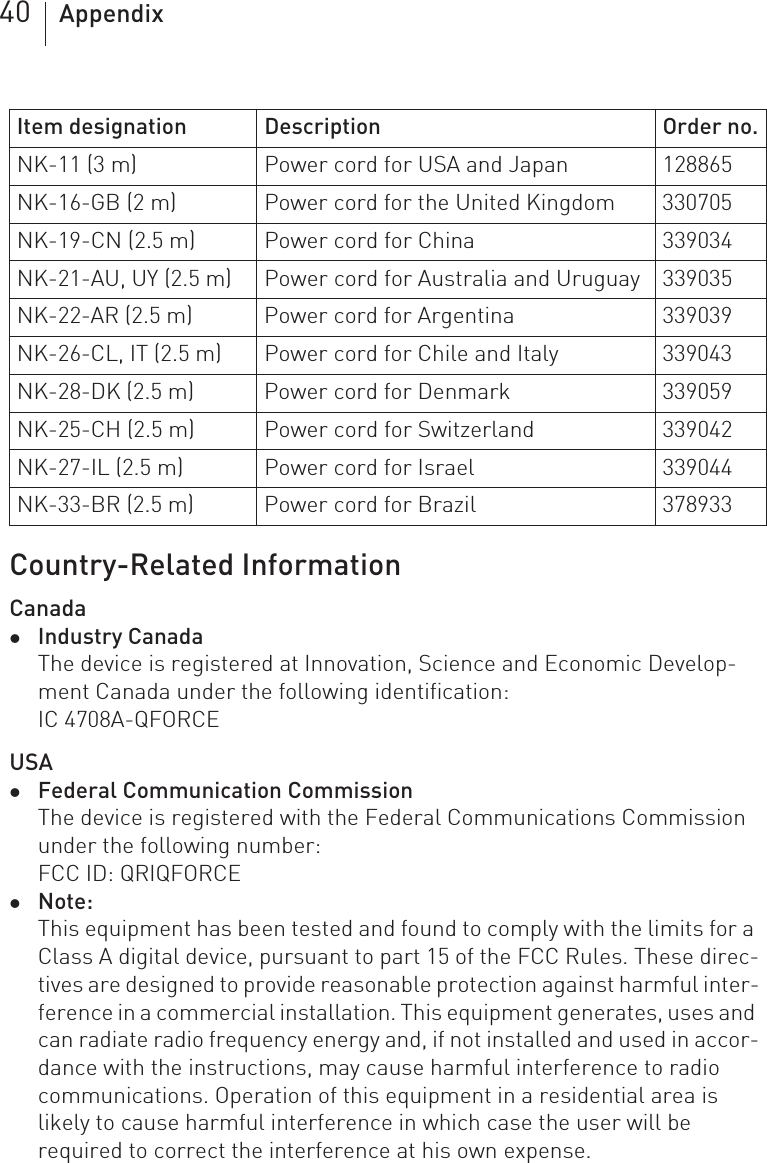
BIOTRONIK SE and KG QFORCE Qubic Force User Manual 418425 D GA Qubic Force en
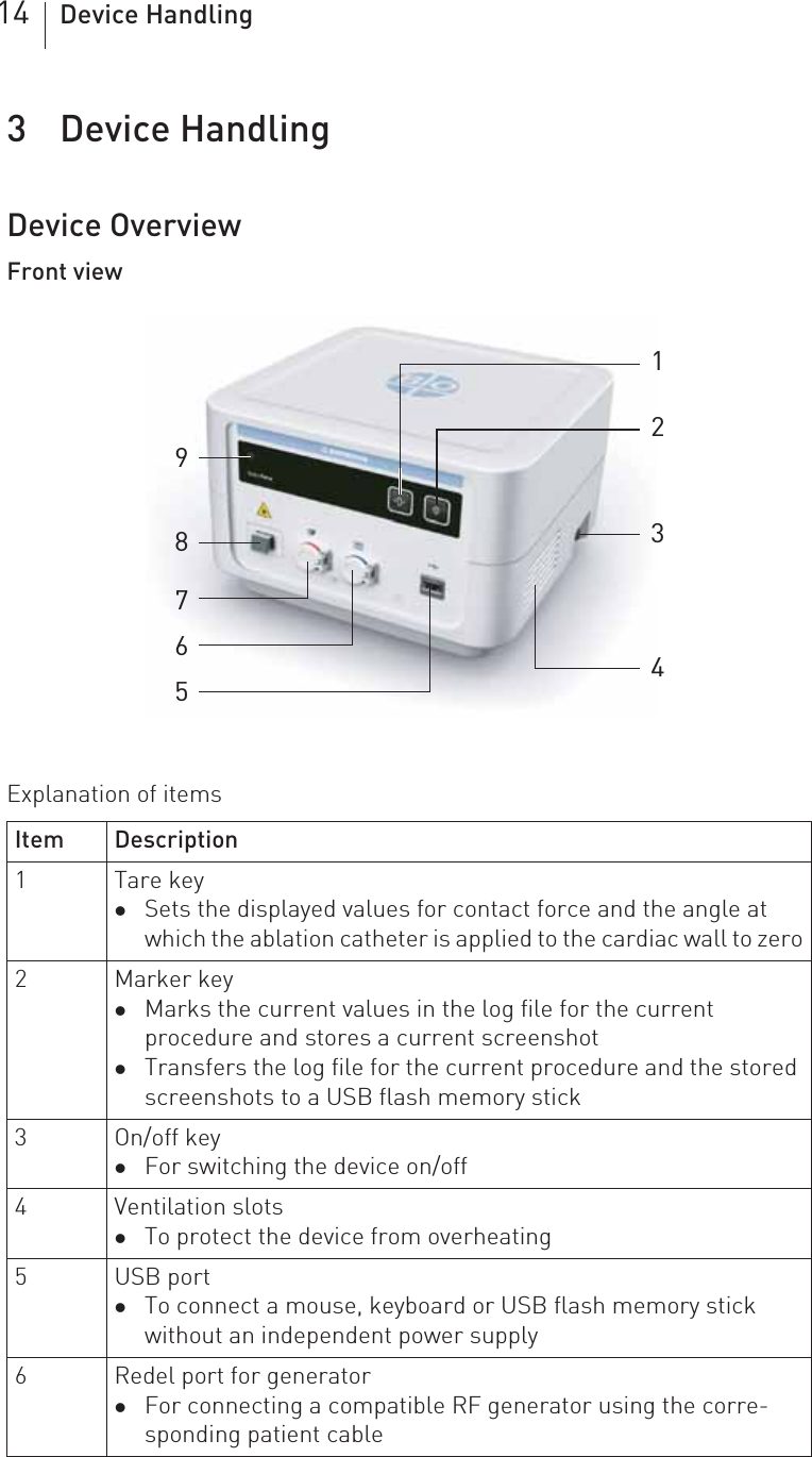
BIOTRONIK SE & Co. KG Qubic Force 418425 D GA Qubic Force en
UserManual.wiki
>
BIOTRONIK SE and KG
>
QFORCE User Manual
15_QFORCE UserMan
Navigation menu
Upload a User Manual
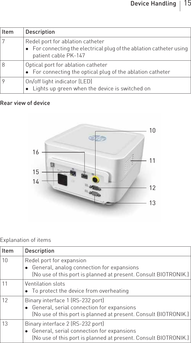
Namespaces
Wiki Guide
HTML
PDF
Info
Views
User Manual
Discussion / Help
Navigation