BIOTRONIK SE and KG QFORCE Qubic Force User Manual 418425 D GA Qubic Force en
BIOTRONIK SE & Co. KG Qubic Force 418425 D GA Qubic Force en
15_QFORCE UserMan
Qubc Force
Devce for vsualzaton of contact force
of the catheter tp on the cardac wall
EP // External devces // Techncal Manual

1
Table of Contents
Table of Contents
Introduction . . . . . . . . . . . . . . . . . . . . . . . . . . . . . . . . . . . . . . . . . . . . . . . . . . . . . . . 2
About the Device . . . . . . . . . . . . . . . . . . . . . . . . . . . . . . . . . . . . . . . . . . . . . . . . .2
About this Technical Manual . . . . . . . . . . . . . . . . . . . . . . . . . . . . . . . . . . . . . . .3
Safety during Use . . . . . . . . . . . . . . . . . . . . . . . . . . . . . . . . . . . . . . . . . . . . . . . . . . 4
Required Expertise . . . . . . . . . . . . . . . . . . . . . . . . . . . . . . . . . . . . . . . . . . . . . . .4
Electromagnetic Interference . . . . . . . . . . . . . . . . . . . . . . . . . . . . . . . . . . . . . .4
General Safety Warnings . . . . . . . . . . . . . . . . . . . . . . . . . . . . . . . . . . . . . . . . . .7
Operating Conditions. . . . . . . . . . . . . . . . . . . . . . . . . . . . . . . . . . . . . . . . . . . . . .9
Maintenance, Care and Disposal . . . . . . . . . . . . . . . . . . . . . . . . . . . . . . . . . . .11
Device Handling . . . . . . . . . . . . . . . . . . . . . . . . . . . . . . . . . . . . . . . . . . . . . . . . . .14
Device Overview . . . . . . . . . . . . . . . . . . . . . . . . . . . . . . . . . . . . . . . . . . . . . . . . .14
Setting up the Device. . . . . . . . . . . . . . . . . . . . . . . . . . . . . . . . . . . . . . . . . . . . .17
Connections and Cables . . . . . . . . . . . . . . . . . . . . . . . . . . . . . . . . . . . . . . . . . .18
Switching On and Off . . . . . . . . . . . . . . . . . . . . . . . . . . . . . . . . . . . . . . . . . . . . .23
Keys on the Device. . . . . . . . . . . . . . . . . . . . . . . . . . . . . . . . . . . . . . . . . . . . . . .24
Using the Software . . . . . . . . . . . . . . . . . . . . . . . . . . . . . . . . . . . . . . . . . . . . . . . .26
The Main View . . . . . . . . . . . . . . . . . . . . . . . . . . . . . . . . . . . . . . . . . . . . . . . . . .26
The Status Bar . . . . . . . . . . . . . . . . . . . . . . . . . . . . . . . . . . . . . . . . . . . . . . . . . .28
The Numerical Display . . . . . . . . . . . . . . . . . . . . . . . . . . . . . . . . . . . . . . . . . . .29
The Graphic Display. . . . . . . . . . . . . . . . . . . . . . . . . . . . . . . . . . . . . . . . . . . . . .30
The Trend Display . . . . . . . . . . . . . . . . . . . . . . . . . . . . . . . . . . . . . . . . . . . . . . .32
The Settings View . . . . . . . . . . . . . . . . . . . . . . . . . . . . . . . . . . . . . . . . . . . . . . .33
Appendix . . . . . . . . . . . . . . . . . . . . . . . . . . . . . . . . . . . . . . . . . . . . . . . . . . . . . . . .36
Technical Data . . . . . . . . . . . . . . . . . . . . . . . . . . . . . . . . . . . . . . . . . . . . . . . . . .36
Parameter Values . . . . . . . . . . . . . . . . . . . . . . . . . . . . . . . . . . . . . . . . . . . . . . .38
Accessories . . . . . . . . . . . . . . . . . . . . . . . . . . . . . . . . . . . . . . . . . . . . . . . . . . . .39
Country-Related Information . . . . . . . . . . . . . . . . . . . . . . . . . . . . . . . . . . . . . .40
Legend for the Label . . . . . . . . . . . . . . . . . . . . . . . . . . . . . . . . . . . . . . . . . . . . .41
Directories. . . . . . . . . . . . . . . . . . . . . . . . . . . . . . . . . . . . . . . . . . . . . . . . . . . . . . .42
Index . . . . . . . . . . . . . . . . . . . . . . . . . . . . . . . . . . . . . . . . . . . . . . . . . . . . . . . . . .42
418425--D

2Introduction
1 Introduction
Introduction1418423Technical ManualQubic Force
About the Device
General description
Qubic Force is used with the AlCath Force ablation catheter, a compatible
radiofrequency (RF) generator, and an external monitor. Qubic Force is a
device for visualization of the contact force of the ablation catheter tip on the
cardiac wall during an electrophysiological study in cardiac catheter labora-
tories with or without cardiac radiofrequency (RF) ablation. An external
monitor is placed in a position easily visible to the user and connected to the
Qubic Force. The contact force is displayed which allows the user to monitor
the contact force of the ablation catheter tip on the cardiac wall, establish
proper contact on the cardiac wall, and influence lesion formation.
Intended medical use
The relevant cardiology association guidelines do not contain a medical
indication for the visualization of the contact force of the catheter tip on the
cardiac wall and therefore contain no indication for the use of Qubic Force.
Qubic Force is not required to perform an electrophysiological study in
cardiac catheter laboratories with or without cardiac radiofrequency
ablation, but this device does provide important information to the user, for
example for the assessment of lesion formation and optimization of ablation
parameters.
Contraindications
There are no specific contraindications for the use of Qubic Force. For infor-
mation on contraindications for the ablation catheter and the RF generator,
please consult their technical manuals.
Patient group
Use of Qubic Force is indicated for all patients subjected to a therapeutic
electrophysiological study. For studies using Qubic Force, there are no
restrictions in terms of the age, sex, weight, state of health, nationality, or
condition of the patient.
Compatible RF generators
The following RF generators are compatible with Qubic Force:
zBIOTRONIK: Qubic RF
zStockert: EP-Shuttle
zBiosense Webster: SmartAblate™ HF Generator (manufacturer: Stockert)
zSt. Jude Medical: IBI-1500 T11
zMedtronic: Atakr II
zOsykpa: HAT 300 Smart

Introduction 3
About this Technical Manual
Objective
This technical manual provides all the safety information required to use the
device.
The following topics are covered in this manual:
zDevice startup
zDevice handling
zUsing the software
Target group
This technical manual is intended for cardiologists, electrophysiologists and
cardiac surgeons possessing knowledge in the following areas:
zCatheterization procedures
zProcedures for ablating the intracardiac stimulation and conduction
systems
This technical manual is also intended for clinical and technical assistants
possessing expertise in handling devices in cardiac catheter laboratories.
Additional required expertise is:
zBasic medical knowledge of the examination method employed
zAbility to work with a PC
zAbility to use software-controlled medical devices
Other Technical Manuals
The following additional technical manuals must be followed to ensure the
safe and correct use of the device:
zTechnical manuals for other system components in the cardiac catheter
laboratory, not supplied with the Qubic Force (e.g., AlCath Force ablation
catheter, RF generator, lab monitoring system, and external monitor)
zTechnical manuals for the intended catheters, indifferent electrodes,
patient cables, and adapters
zTechnical manuals for other designated accessories

4Safety during Use
2 Safety during Use
Safety during Use2418423Technical ManualQubic Force
Required Expertise
Required expertise
Qubic Force is intended for use by cardiologists, electrophysiologists,
cardiac surgeons, and clinical and technical assistants specialized in
handling devices in cardiac catheter laboratories and trained in handling the
Qubic Force. In addition to having basic medical knowledge, the user must
be thoroughly familiar with the electrophysiology of the heart, catheteriza-
tion procedures, and the method of ablating the intracardiac stimulation and
conduction system.
Only trained and qualified medical personnel with this knowledge can
properly operate the device.
Electromagnetic Interference
Possible electromagnetic interference
This device is protected against electromagnetic interference and electro-
static discharges in the specialized environment of a cardiac catheter labo-
ratory containing high-frequency surgical instruments and X-Ray devices.
At the same time, the emitted interference is reduced to a minimum.
The device thus fulfills the requirements of EN 60601-1-2 as they apply to
CISPR 11 class A in relation to both interference emitted and resistance to
interference. The following norms do not apply here:
zIEC 61000-3-2
Harmonic distortion (harmonic currents in the mains supply)
zIEC 61000-3-3
Voltage fluctuations and flicker in the mains supply
Note: Please note that in principle there is a risk of cardiac wall perforation
during a cardiac radio frequency ablation and that this cannot entirely be
excluded despite the use of Qubic Force. Therefore, take any measures to
minimize this risk as much as possible.

Safety during Use 5
The following tests were performed according to IEC 60601-1-2: 2014:
Even when, as pointed out above, the device complies with the requirements
of EN 60601-1-2, strong electromagnetic disturbances may occur in the
immediate vicinity of electrical motors, high-voltage power lines, PCs,
monitors and other – perhaps defective – electrical devices which may cause
the Tare key to be triggered unintentionally and may sometimes impair the
functioning of the device.
Section of
IEC 60601-
1-2:2014
Test Test level
7.1 EN 55011 (CISPR 11)
Conducted interference
emissions
zGroup 1
zClass A
EN 55011 (CISPR 11)
Radiated emissions
8.9 IEC 61000-4-2
Electrostatic discharge
(ESD)
z±8 kV contact discharge
z±15 kV air discharge
8.9 / 8.10 IEC 61000-4-3
Electromagnetic fields
zModulation: 1 kHz
z3 V/m, 80 MHz – 2.7 GHz
zLimits for RF communication
equipment per Table 9 in
IEC 60601-1-2 (9-28 V/m)
8.9 IEC 61000-4-4
Transient conducted
surge voltages (EFT,
bursts)
z± 2kV mains supply
z± 1kV signal line
IEC 61000-4-5
Surge voltage waves on
supply lines
z± 2 kV common mode
z± 1 kV common mode
IEC 61000-4-6
Conducted radio-
frequency interference
zModulation: 1 kHz
z3 V
z6 V in ISM bands
IEC 61000-4-8
Power frequency magnetic
fields
z30 A/m
z50/60 Hz
IEC 61000-4-11
Voltage fluctuations and
interruptions in supply
voltage

6Safety during Use
This kind of device malfunction should be considered as a possible cause if
the following is observed:
zThe values displayed for contact force and application angle are set to
zero with the AlCath Force ablation catheter connected, as long as the
Tare key has not been pressed.
zThe device displays other inexplicable behavior.
Correct operation of the device can be restored with the following miscella-
neous measures:
zSwitch off electronic device generating the disturbance.
zRemove the source of interference from the device.
zSwitch the device on and off or break the electrical connection between
the device and the source of the interference if this can be done safely.
If the interference continues, contact BIOTRONIK immediately.
WWARNING
Risk of electromagnetic interference through the use of unauthorized
accessories
The use of accessories, transducers or cables not listed by BIOTRONIK or
of accessories other than those specified by BIOTRONIK, can produce
elevated electromagnetic emissions or cause degradation in the device's
resistance to electromagnetic interference. Such effects can lead to the
faulty operation of the device.
zUse only accessories authorized by BIOTRONIK.
WWARNING
Risk of electromagnetic interference through the use of portable RF
communication devices
If portable RF communication devices (including peripheral devices such as
antenna cables and external antennae) are operated closer than 30 cm (12
inches) from this device, this can result in a reduction in its performance.
This applies even if using the cables specified by BIOTRONIK.
zWhen operating portable RF communication devices (including periph-
eral devices such as antenna cables and external antennae), keep such
devices at a distance of at least 30 cm (12 inches) from this device.

Safety during Use 7
General Safety Warnings
Risks of improper handling
Disregarding the safety warnings can endanger the patient, the staff and the
equipment.
The following dangers can, for example, arise in the event of improper use:
zFailure of important device functions
zPersonal endangerment due to electrical impact
Changes not permitted
Only the manufacturer or a party expressly authorized by BIOTRONIK may
perform corrective maintenance, enhancements or modifications to the
device.
Replacement parts and accessories
Use only accessories authorized by BIOTRONIK. Using any other parts voids
liability for any consequences, as well as the product guarantee and
warranty.
RF accessories
Use only RF accessories certified according to Standard IEC 60601-2-2.
Defective devices
Do not use defective or damaged devices.
Physician supervision
The device may only be used under the constant supervision of a physician.
The patient must be monitored at all times using an external surface ECG
with rate control.
Patient observation
Ensure that patients are individually observed over a suitable period of time
in order to monitor the compatibility and effectiveness of the electrophysio-
logical therapy.
Emergency equipment
During an examination, keep resuscitation equipment (e.g., cardiac defibril-
lator, external pacemaker) available and ready for use at all times in order
to perform life-supporting measures immediately in the event of an emer-
gency.
Note: Failure to observe the safety warnings voids all damage claims and
manufacturer liability.

8Safety during Use
Liquids
Never use a damp or wet device. Protect the device from accidental ingres-
sion of fluids (e.g. infusion fluids).
If the device becomes wet, immediately unplug and stop using the device.
Contact BIOTRONIK for testing and, if necessary, repair of the device.
Electrostatic potentials
Ensure that electrostatic potentials between medical staff and patients are
balanced. Before handling the device, the electrostatic potential between the
physician or medical staff and the patient must be balanced by touching the
patient at a point as far away from the catheters or leads as possible.
Leakage currents
Avoid leakage currents between all connected devices. Such leakage
currents can cause lethal arrhythmias.
Potential equalization cables must be attached to all connected compo-
nents, if present.
Before initial commissioning, check and document all device combinations.
National and international directives concerning the use of electromedical
devices also apply to patient cables.
Touching contacts on cables and catheters
Do not touch the contacts on the patient cable or the catheters. The device
has electrical contact with the patient's heart and blood via the implanted
catheters. Touching the contacts on the patient cable or catheters could
expose the patient's heart to dangerous electrical currents.
Defibrillation
When connected with the approved patient cable, the device is defibrillation
protected. However, damage cannot be ruled out in all circumstances.
Following a defibrillation, the recovery time can take up to 10 seconds until
the device is ready for use again. Check all functions of the device, following
a defibrillation. During defibrillation, do not touch the patient, the device the
patient is connected to, or the attached accessories. Otherwise, there is a
danger that you may suffer an electrical shock.
Risk of infection
Contaminated devices can lead to infection. Clean and disinfect the device on
a regular basis. Refer to the cleaning instructions for all other system
components.

Safety during Use 9
Operating Conditions
Storage and transportation
If the packaging is damaged, please contact BIOTRONIK immediately. Do not
put the device into operation.
The ambient conditions for shipping and storage are:
Operating conditions
Temperature 0°C ... +50°C
Relative humidity 30% ... 75%, no condensation
Atmospheric pressure 700 ... 1060 hPa
Note: After transporting the equipment from a cold to a warm area, conden-
sation may form, particularly on metal parts of the device, and damage the
electronics.
zAfter transport, wait approximately 2 hours until the device has reached
room temperature and the condensation has dried up before using the
system.
WWARNING
Risk of electromagnetic interference
The use of this device close to or in direct contact with other devices should
be avoided, as this may lead to the device operating incorrectly.
zWhere usage in such a manner is unavoidable, you should monitor this
device and the device or devices being used together with it in order to
check that they are all working correctly.
WWARNING
Risk of electromagnetic interference through the use of portable RF
communication devices
If portable RF communication devices (including peripheral devices such as
antenna cables and external antennae) are operated closer than 30 cm (12
inches) from this device, this can result in a reduction in its performance.
This observation also applies even to the specified cable.
zWhen operating portable RF communication devices (including periph-
eral devices such as antenna cables and external antennae), keep such
devices at a distance of at least 30 cm (12 inches) from this device.
10 Safety during Use
Only operate the device in rooms that fulfill the following conditions:
zNo danger of explosion
zSuitable for medical purposes
zClass I power outlet with protective conductor connection
Place the device in a position protected from spray water. Place the device
on a flat, dry surface. Place the device in a position where it cannot slip, even
with cables connected, nor be touched by the patient, and so that you can pull
the power plug out of the device at any time. Make sure that the ventilation
slots remain unobstructed. The device cannot be sterilized and therefore
must not be operated in sterile areas.
The ambient conditions for operation are:
Power supply
The device is operated via the AC voltage (100 to 240 V at 50 / 60 Hz) of a room
used for medical purposes.
The electrical port must fulfill the following conditions:
zThe power outlet fulfills at least the requirements of IEC 60364-7-
710:2002 group 2.
zThe device cable feeds directly into a permanently installed socket. No
portable multiple socket outlets may be used.
zWhen used in combination with other devices, no portable multiple socket
outlets should be used.
zOnly power cords which are suitable for medical devices can be used,
such as power cords from BIOTRONIK or equivalent power cords labeled
H05VV 3 x 0.75 mm, H05VV 3 x 1 mm, or SJT AWG18.
To disconnect Qubic Force from the mains supply, pull the power plug out of
the device.
Temperature +10°C ... +40°C
Relative humidity 30% ... 75%, no condensation
Atmospheric pressure 700 ... 1060 hPa
Operation at altitudes Up to 2000 m AMSL
WCAUTION
Possibility of electric shock
To avoid the risk of electric shock, connect the device only to a power supply
fitted with a PE conductor.

Safety during Use 11
Cable and plug connections
zReplace any cable that shows even slight damage.
zLay all cables between the patient and the device, as well as within the
measuring apparatus, in such a way that they pose no danger of tripping
and that any tensile forces that may occur can be safely buffered.
zEnsure that the contacts of all connector ports and connectors are clean.
Soiled contacts can lead to signal distortions, and thus to false diagnoses.
zEnsure that there is no condensation on the plugs or in the connector
ports. If condensation is present, dry it before use.
zDo not force the plugs into the connector ports. Do not pull on the cable
when disconnecting the plugs. Rather, release the lock on the plug.
Maintenance, Care and Disposal
General information
Cleaning and disinfecting
zUse lint-free, soft cloths.
zClean the housing with a damp cloth and mild soap solution or 70%
isopropanol.
zDisinfect with alcohol-based agents such as Aerodesin 2000.
WWARNING
Allergic reaction
The cable material may trigger allergic reactions in extremely rare cases.
zPrevent the cable from contacting the skin or wounds.
Note: Note the following points before cleaning and disinfecting:
zDisconnect the power plug before cleaning and disinfecting the device
surfaces.
zLet cleaning and disinfection agents evaporate before operating the
device.
zDo not use any strong and abrasive cleaning agents or organic solvents
such as ether or benzine, as they corrode the surface of the device.

12 Safety during Use
Sterilization
zThe device is not sterile and cannot be sterilized.
Test before each use
zA test of the device and the approved accessories should be performed
prior to each use. This test consists of the following visual inspections and
a simple functional test:
– Inspect the housing for mechanical damage, dents, loose parts,
cracks, etc.
– Inspect cables and connection areas to ensure proper insulation, the
absence of breaks, etc.
– Inspect the labeling for legibility.
– Perform a simple electrical function test by switching on the device.
An internal function test is performed automatically.
If no error message appears, then no errors were found and the device
can be used.
– Inspect the displays (e.g., display of characters and language).
Inspection
The inspection consists of the regular safety inspection according to medical
device standards. This ensures the safety of the device.
zInspections should be performed:
– If malfunctions are suspected
– Once a year
zThe inspection can be performed by BIOTRONIK.
zThe inspection must conform to the manufacturer's specifications. These
are available upon request. The specifications list all necessary test steps
and the necessary equipment.
zThe instructions for performing the inspection are directed at people
whose education, knowledge, and experience obtained through practical
work provide the basis for proper execution.
WCAUTION
Infection of the patient from operation of the non-sterile device
Qubic Force is not sterile and cannot be sterilized. If, during the ablation
therapy of the patient, the physician operates the device at the same time,
infection of the patient can result.
zDuring ablation therapy, do not operate the device at the same time.
Safety during Use 13
Fuse replacement
The fuses are located above the power cord port in a fuse holder.
Disposal
zThis device contains materials that must be correctly disposed of in
accordance with environmental protection regulations. The European
Directive 2012/19/EC regarding waste electrical and electronic
equipment (WEEE) applies.
zThe symbol on the label – a crossed out garbage can – indicates that the
device must be disposed of in accordance with the WEEE directive. The
black bar indicates that the device was delivered after the national imple-
mentation of the WEEE directive had been enforced locally.
zReturn devices that are no longer in use to BIOTRONIK.
Disposal of cables
Uncontaminated cables must be disposed of in accordance with Directive
2012/19/EU on waste electrical and electronic equipment (WEEE) or in
accordance with the regulations applicable locally.
Step Action
1 Turn the device off and unplug the power cord.
2 Use a suitable tool to pull the fuse holder out.
3 Replace the old fuses with new ones of the same type.
4 Re-insert the fuse holder. Ensure that it locks securely in
place.
Note: Defective fuses can indicate a technical defect in the device. Conduct
an inspection after changing fuses and before resuming operation of the
device.
Note: Cables that are to be disposed of must be treated as medical waste,
in accordance with environmental regulations, if they have been in contact
with blood.
14 Device Handling
3 Device Handling
Device Handling3418423Technical ManualQubic Force
Device Overview
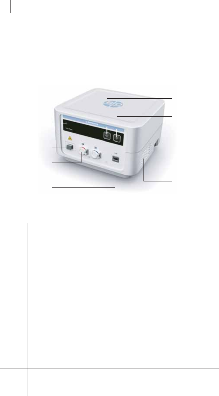
Front view
Explanation of items
Item Description
1Tare key
zSets the displayed values for contact force and the angle at
which the ablation catheter is applied to the cardiac wall to zero
2 Marker key
zMarks the current values in the log file for the current
procedure and stores a current screenshot
zTransfers the log file for the current procedure and the stored
screenshots to a USB flash memory stick
3On/off key
zFor switching the device on/off
4 Ventilation slots
zTo protect the device from overheating
5 USB port
zTo connect a mouse, keyboard or USB flash memory stick
without an independent power supply
6 Redel port for generator
zFor connecting a compatible RF generator using the corre-
sponding patient cable
1
2
3
4
9
5
8
7
6
Device Handling 15
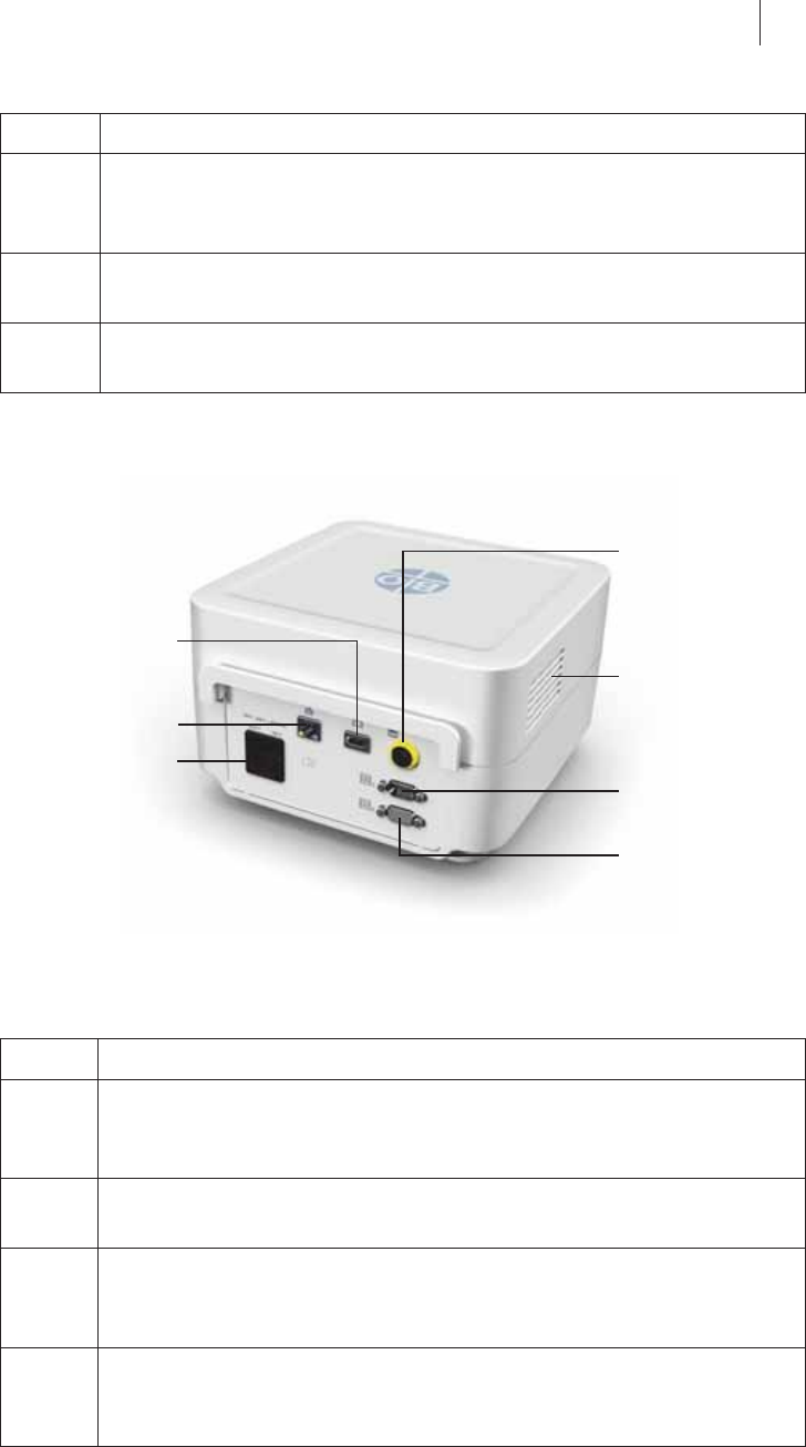
Rear view of device
Explanation of items
7 Redel port for ablation catheter
zFor connecting the electrical plug of the ablation catheter using
patient cable PK-147
8 Optical port for ablation catheter
zFor connecting the optical plug of the ablation catheter
9 On/off light indicator (LED)
zLights up green when the device is switched on
Item Description
10 Redel port for expansion
zGeneral, analog connection for expansions
(No use of this port is planned at present. Consult BIOTRONIK.)
11 Ventilation slots
zTo protect the device from overheating
12 Binary interface 1 (RS-232 port)
zGeneral, serial connection for expansions
(No use of this port is planned at present. Consult BIOTRONIK.)
13 Binary interface 2 (RS-232 port)
zGeneral, serial connection for expansions
(No use of this port is planned at present. Consult BIOTRONIK.)
Item Description
10
11
13
12
15
14
16
16 Device Handling
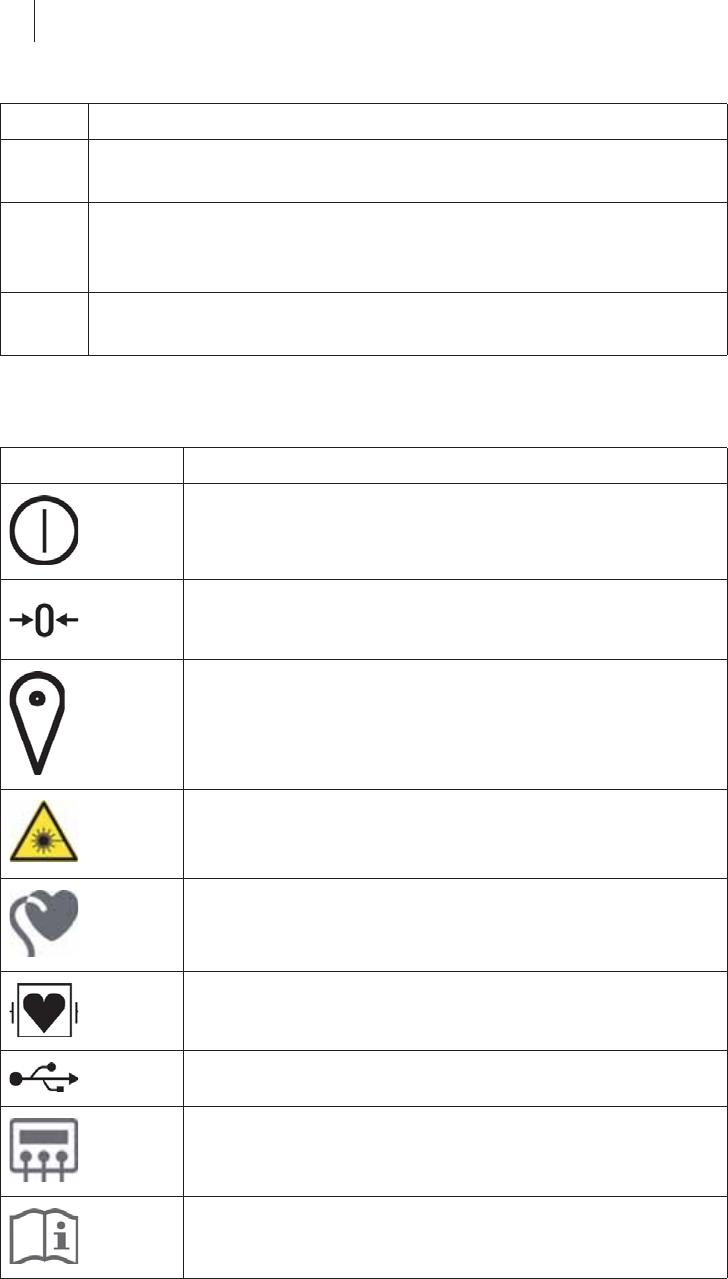
Symbols on the device
Explanation of symbols
14 Power cord port and device fuse
zFor connecting the power cord
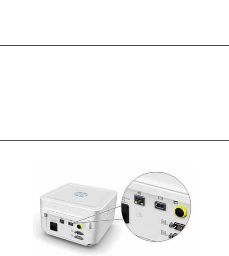
15 Ethernet port (not suitable for network connection)
zGeneral, digital connection for expansions
(No use of this port is planned at present. Consult BIOTRONIK.)
16 Monitor port
zTo connect a monitor
Symbol Description
On/off light indicator
Tare
Marker
Warning of invisible intense light from an SLED
Since this light corresponds to laser class 1, this optical
port poses no risk to the user or patient.
Ablation catheter
Type CF applied part, defibrillation protected
USB port
Radiofrequency unit of the RF generator
Follow the instructions for use
Item Description
Device Handling 17
Setting up the Device
General
Qubic Force must be set up in such a way that it can be connected up to the
RF generator and to an external monitor. Connect an external monitor with
a display screen of at least 10 inches that can display to a resolution of 1024
x 768 pixels. Set up the monitor so that it can be viewed easily by the user and
is not positioned any further than 1.5 m from the user during any electro-
physiological examination. Depending on the display screen size being used,
it may be possible to increase the distance of the user from the monitor with
a resolution of 1024 x 768 pixels.
Setting up the device
zPlace the device in a position protected from spray water. Place the device
on a flat, dry surface. Place the device in a position where it cannot slip,
even with cables connected, nor be touched by the patient, and so that you
can pull out the power plug on the device at any time. Make sure that the
ventilation slots remain unobstructed.
The physician must not touch any plug connections such as USB ports
and the patient at the same time.
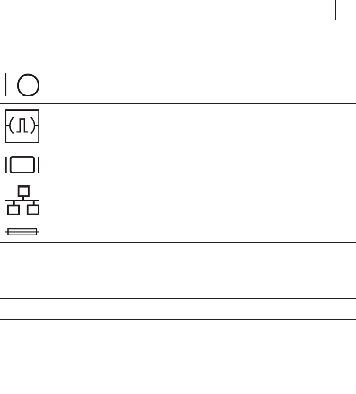
On/off key
Binary interface 1 or 2
Monitor port
Ethernet
Fuse
WCAUTION
Functional impairment due to external damage
Mechanical impact can permanently impair the function of an unpackaged
system even from a height of 5 cm (roughly 2") or greater.
zDo not use if the device or the packaging is visibly damaged.
zContact BIOTRONIK for testing and, if necessary, repair of the device.
Symbol Description
18 Device Handling
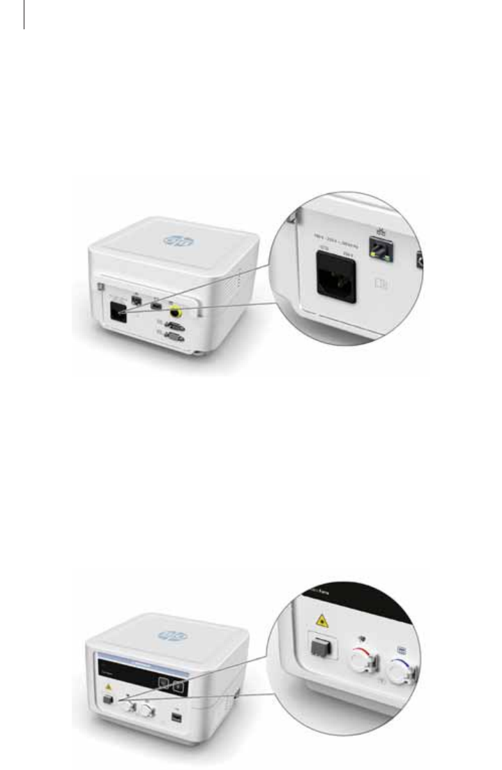
Connections and Cables
Connecting the power cord
The power cord port on the device is designed to accept the power cord. The
power cord port is located on the rear side of the device.
Before connecting, ensure that the power supply conditions are met (see
Power supply, p. 10).
zConnect the power cord to the power cord port on the device.
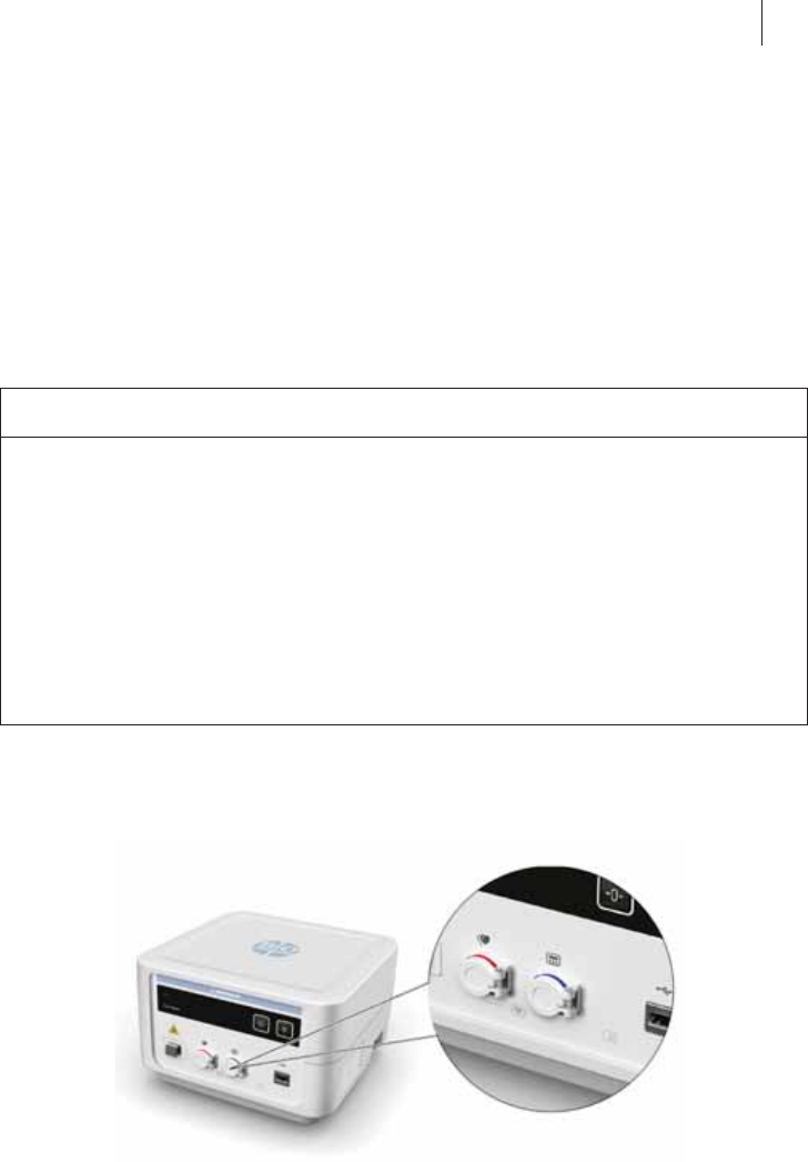
Connecting ablation catheters
The AlCath Force ablation catheter is connected using the PK-147 cable. The
Redel port for the electrical plug of the ablation catheter is marked red and
is located on the front of the device. The optical port for the optical plug of
the ablation catheter is also located on the front of the device.
zConnect the PK-147 cable to the red Redel port on the device.
zConnect the PK-147 cable to the AlCath Force ablation catheter.
zConnect the optical plug on the ablation catheter to the optical port on the
device.
Refer to the technical manual of the ablation catheter.
Once connected, it may take up to 10 s before the ablation catheter can be
used.
Device Handling 19
The first connection of the AlCath force ablation catheter to Qubic Force is
stored and, from this time, the AlCath Force ablation catheter can be used
for 24 hours. During this time, you can remove the AlCath Force ablation
catheter from the device, for example.
The values used to obtain contact force and application angle are automati-
cally tared by the device upon first connecting the AlCath Force ablation
catheter and each time the Qubic Force is started.
Connecting the RF generator
The Redel port on the Qubic Force for the RF generator is marked blue and
is located on the front of the device:
zSelect the appropriate patient cable for the RF generator that you are
using.
zConnect the appropriate patient cable to the Redel port marked in blue on
the Qubic Force.
zConnect the appropriate patient cable to the Redel port for the ablation
catheter on the RF generator.
Follow the instructions in the technical manual for the RF generator and
for the patient cable that you are using.
WCAUTION
There is a risk of exceeding the leakage current limits when connecting
external devices that have their own power supply as well as a risk of
making an electrically conductive connection to other devices.
zConnect to the covered blue Redel port for the RF generator only devices
that comply with IEC 60601-2-2 standard and are CF-type applied parts.
zBefore initial commissioning, check and document all device combina-
tions according to IEC standard 60601-1.
zPerform this inspection at least once per year according to the legal
requirements.

20 Device Handling
The following RF generators are connected using the correct patient cable
as indicated below:
RF generator Patient cables
Qubic RF PK-147
EP-Shuttle
SmartAblate HF Generator PK-150
IBI-1500 T11 PK-142
Atakr II PK-112
HAT 300 Smart PK-111
Note: While the AlCath Force ablation catheter and an RF generator are
connected to Qubic Force it is always possible to start a cardiac radio
frequency ablation, even if there is an error in how the contact force is
displayed or if the Qubic Force is switched off.
Device Handling 21
Connecting an external monitor
The monitor port is located on the rear side of the device.
zUsing the VK-124 cable, connect the external monitor to the monitor port.
The device has a monitor port for connecting it to an external monitor with
the VK-124 cable. Connect an external monitor with a display screen of at
least 10 inches that can display to a resolution of 1024 x 768 pixels. Set up
the monitor so that it can be viewed easily by the user and is not positioned
any further than 1.5 m from the user during any electrophysiological study.
Depending on the display screen size being used, it may be possible to
increase the distance of the user from the monitor with a resolution of
1024 x 768 pixels.
WCAUTION
Risk of exceeding the leakage currents when connecting external devices
with their own power supply or an electrically conductive connection to
other devices
zOnly connect devices that comply with IEC 60601-1 standard or
IEC 60950.
zBefore initial commissioning, check and document all device combina-
tions according to IEC standard 60601-1.
zPerform this inspection at least once per year according to the legal
requirements.
22 Device Handling
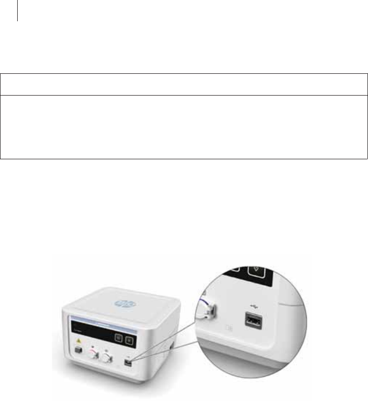
Connecting keyboard, mouse or USB stick
The USB port on the device is designed solely for connection of a mouse, a
keyboard or a USB flash memory stick (USB flash drive) without an indepen-
dent power supply. You can connect and disconnect these accessories while
the device is still active.
The USB port is located on the front of the device.
zConnect the mouse, keyboard or USB stick to the USB port.
WWARNING
Risk of energy being conducted to the patient
If the device and the patient are touched at the same time, electrical energy
can be conducted from the device into the patient.
zNever touch the device and the patient at the same time.
Device Handling 23
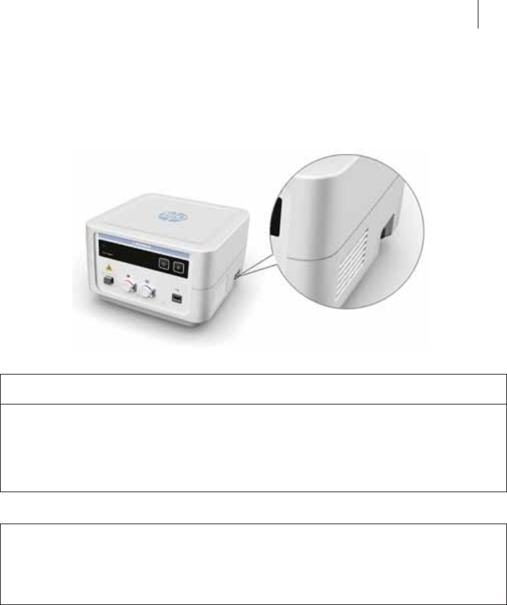
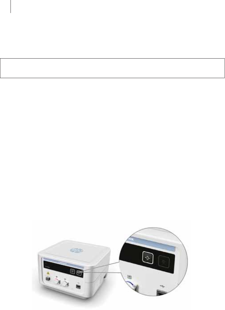
Switching On and Off
Switching the device on and off
The on/off key is located on the right side at the rear of the device.
zTo switch the device on or off, press the on/off key.
After switching on the device, the on/off light indicator on the front left
lights up and Qubic Force performs a self-test. After the self-test, the
main view appears on the external monitor.
zTo disconnect Qubic Force from the mains supply, pull the power plug of
the device.
WWARNING
Risk of energy being conducted to the patient
If the device and the patient are touched at the same time, electrical energy
can be conducted from the device into the patient.
zNever touch the device and the patient at the same time.
Note: While the AlCath Force ablation catheter and a RF generator are
connected to Qubic Force it is always possible to start a cardiac radio
frequency ablation, even if there is an error in how the contact force is
displayed or if the Qubic Force is switched off.
24 Device Handling
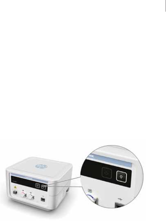
Keys on the Device
Tare key
During insertion and positioning of the AlCath Force ablation catheter in the
heart, the vectors indicating the values for determination of contact force
and the application angle are identified and transmitted to the device. This
means that values for contact force and the application angle are already
displayed before the actual cardiac radiofrequency ablation is performed. It
may be useful to set these values to zero prior to beginning the cardiac
radiofrequency ablation so as to better assess the applied contact force and
the application angle. The displayed values for the contact force and angle
are set to zero using the Tare key.
The device is automatically tared upon first connecting the AlCath Force
ablation catheter to it and each time the Qubic Force is started. When you
disconnect the ablation catheter and then connect it again while the device
is still active, the values used to obtain contact force and application angle
are not automatically tared again.
The Tare key is located towards the upper right on the front of the device.
zPress the Tare key to set the displayed values for contact force and the
angle to zero.
Note: In order to prevent incorrect values for the contact force, make sure
that no force is acting on the cardiac wall when you press the Tare key.
Device Handling 25
Marker key
A log file for the current procedure is created when an AlCath Force ablation
catheter is connected. The log stores values including the contact force and
the application angle.
The following can be done using the Marker key:
zMark the current values in the log file for the current procedure and store
a screenshot.
zTransfer the log file for the current procedure and all stored screenshots
to a connected USB stick.
The log file for the current procedure exists only until another AlCath Force
ablation catheter is connected. Connecting a new AlCath Force ablation
catheter overwrites the existing log file for the current procedure.
The Marker key is located on the upper right on the front of the device.
Do the following to mark the current values in the log file for the current
procedure and to store a screenshot:
zPress the Marker key for less than 5 seconds.
The screenshot is backed up to a USB flash memory stick, if connected.
Do the following to transfer the log file for the current procedure and all
stored screenshots to a connected USB stick:
zHold the Marker key down for more than 5 seconds.
26 Using the Software
4 Using the Software
Using the Software4418423Technical ManualQubic Force
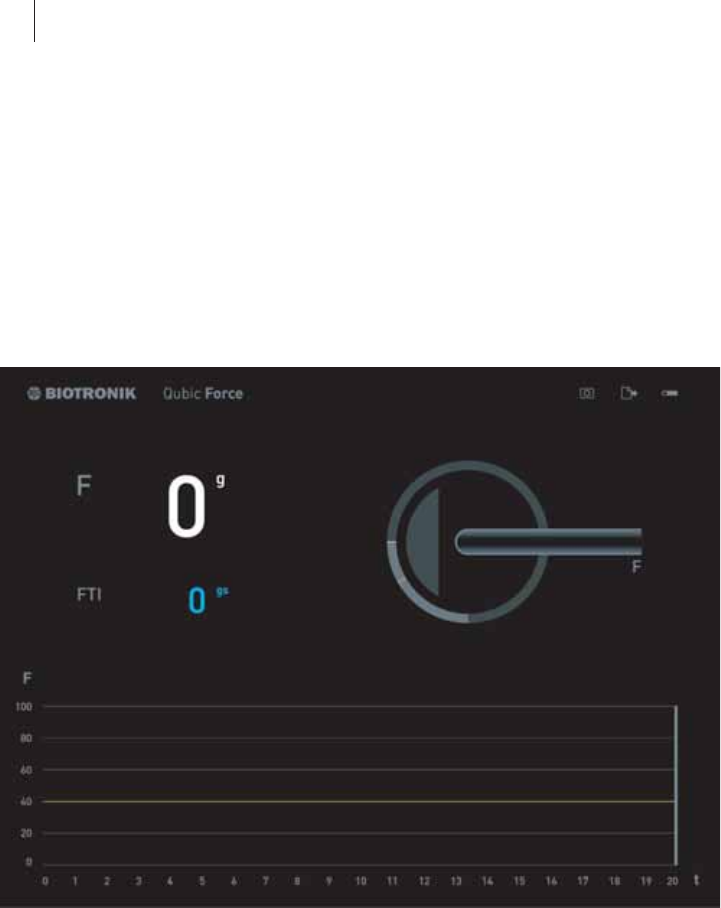
The Main View
General overview
After switching on the device, the on/off light indicator on the front left lights
up and Qubic Force performs a self-test. After the self-test, the main view
appears on the external monitor.
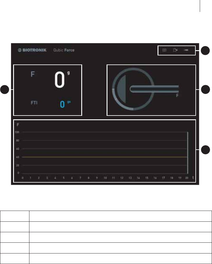
Using the Software 27
Areas of the screen
The Qubic Force screen contains four areas that present information differ-
ently:
Item Explanation
1 Status bar
2 Numerical display
3 Graphic display
4 Trend display
1
3
2
4
28 Using the Software
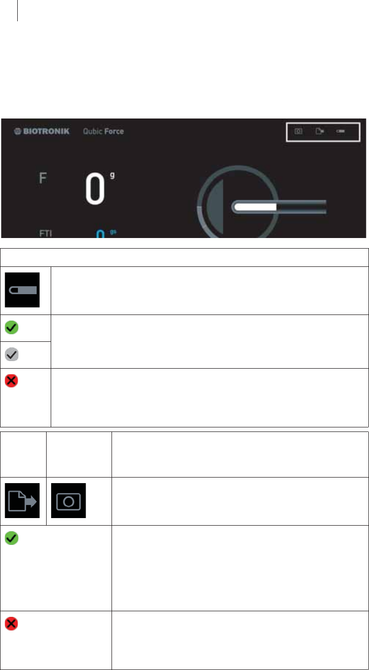
The Status Bar
General overview
The status bar is located at the top right edge. It is visible in the main view
and the Settings view.
Symbol AlCath Force ablation catheter
zNo AlCath Force ablation catheter has been connected.
zAn AlCath Force ablation catheter has been connected,
checked successfully, and can be used.
The green marker changes to gray after 10 seconds.
zAn AlCath Force ablation catheter has been connected but an
error occurred and it cannot be used.
zA connected AlCath Force ablation catheter has been
removed.
Data
export
symbol
Marker and
screenshot
symbol
Explanation
zHave not been used during the current electro-
physiological study
zData has been successfully exported or the
screenshot has been stored and the current
values marked in the log file for the current
procedure.
The green marker changes to gray after
10 seconds.
zAn error has occurred and the data has not been
successfully exported or no screenshot has been
stored and the current values have not been
marked in the log file for the current procedure.
Using the Software 29
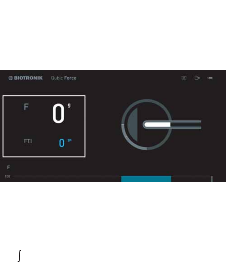
The Numerical Display
General overview
The numerical display is located in the left main area of the screen.
If an AlCath Force ablation catheter is connected, the following current
values are shown:
zF: The current contact force of the ablation catheter tip on the cardiac
wall, in grams (g)
zFTI: The current force-time integral in gram seconds (gs)
The force-time integral is calculated from the following formula:
zt1: Start of radiofrequency ablation
zt2: End or duration since start of radiofrequency ablation
zF: Current contact force
If there is no ablation catheter AlCath Force connected, no information will
be displayed in this area.
FTI: F (t) *dt
t1
t2
30 Using the Software
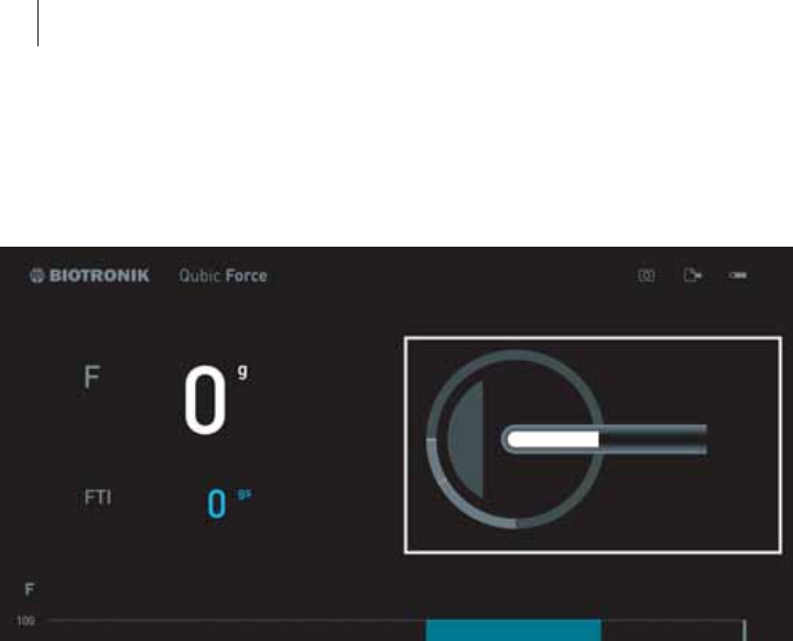
The Graphic Display
General overview
The graphic display is located in the right main area of the screen.
If an AlCath Force ablation catheter is connected, the following information
is displayed graphically depending on the configuration of the device:
zThe angle at which the ablation catheter is applied to the cardiac wall
zThe delivery of ablation energy (only if a RF generator is connected to
Qubic Force.)
zExceedance of the set contact force limit
zA possible foreseeable perforation of the cardiac wall because the
following values are not within the respective tolerance range:
– The contact force is above the set limit.
– And the angle at which the ablation catheter is applied to the cardiac
wall is below the set limit.
The contact force limit (Fmax = 40 g) is preset in the factory settings. To adjust
this value and also set the visual warning limit for the angle at which the
ablation catheter is applied to the cardiac wall, a mouse or keyboard must
be connected and you have to switch to the Settings view (The Settings View,
p. 33).
Using the Software 31
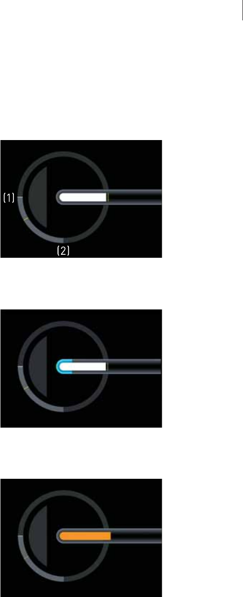
Display of the angle at which the ablation catheter is applied to the
cardiac wall
zThe white line in the light gray area of the circle moves between
0° (1) and 90° (2). The orange line shows the angle limit.
The area within the circle symbolizes the cardiac wall and moves
according to the angle of the catheter on the cardiac wall.
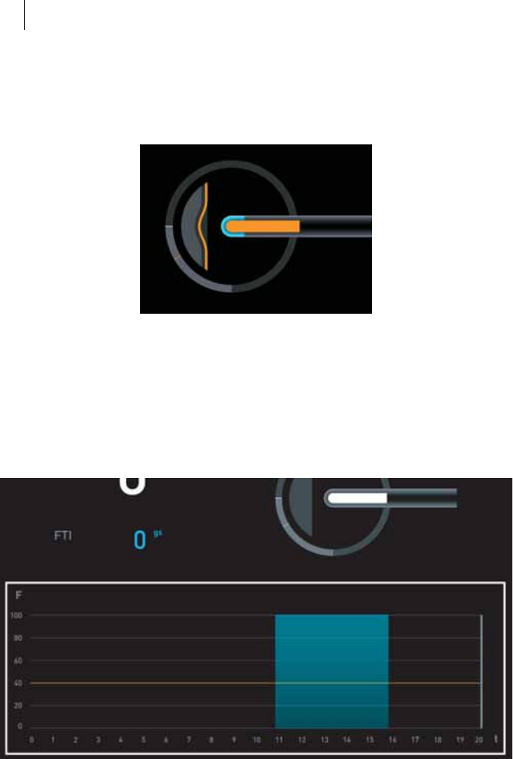
Display of the delivery of ablation energy
zThe catheter tip turns blue.
Display of exceedance of the set contact force limit
zThe white area inside the catheter display turns orange.
In the numerical display on the left side, the value for contact force is also
shown in orange.
32 Using the Software
Indication of possible perforation of the cardiac wall
zThe white area inside the catheter display turns orange.
The display of the cardiac wall turns orange and shows an indentation.
In the numerical display on the left side, the value for contact force is also
shown in orange.
The Trend Display
General overview
The trend display is located in the lower area of the screen.
If an AlCath Force ablation catheter is connected, the following information
is displayed depending on the configuration of the device:
zContact force over time
F: Contact force in grams (g)
t: Time in seconds (s)
zThe orange line marks the set contact force limit.
zThe blue range highlights the delivery of ablation energy (only if a RF
generator is connected to Qubic Force).
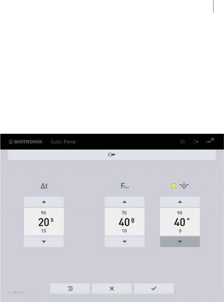
Using the Software 33
The contact force limit (Fmax = 40 g) and the duration of the trend display
(t = 20 s) are preset in the factory settings. To adjust these values, a mouse
or keyboard must be connected and you have to switch to the Settings view
(The Settings View, p. 33).
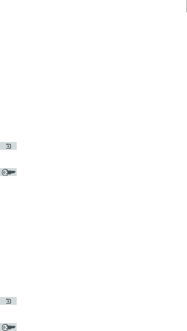
The Settings View
Switching to the Settings view
zConnect a keyboard or mouse to the USB port.
zPress any key.
Overview
You can set the following values in the Settings view:
zΔt: Duration of the trend display
zFmax: Contact force limit
zLimit for the angle at which the ablation catheter can be applied to the
cardiac wall
Setting a limit (0...90°) activates the visual warning for a possible foresee-
able perforation of the cardiac wall in the graphic display of the main view.
Also, the checkbox lights up green.

34 Using the Software
Closing the Settings view
zIf you have connected a keyboard, there are three ways of closing the
Settings view:
– Press the Esc key.
Your changed settings will not be applied.
– Navigate to the button with the checkmark using the tab key and
confirm by pressing the Enter key.
Your changed settings will be applied.
– Navigate to the button with the cross using the tab key and confirm by
pressing the Enter key.
Your changed settings will not be applied.
zIf you have connected a mouse, there are two ways of closing the Settings
view:
– Click with the mouse pointer on the button with the checkmark.
Your changed settings will be applied.
– Click with the mouse pointer on the button with the cross.
Your changed settings will not be applied.
The Settings view closes automatically once one of the following actions is
performed:
zAn AlCath Force ablation catheter is connected.
zA key on the device is pressed.
Using the Software 35
Working with the keyboard
The button that is activated and whose value you can change is surrounded
by a frame.
zSwitching between the buttons:
Press the Tab key on the keyboard.
zActivating/confirming a button:
Press the Enter key on the keyboard.
zChanging the values:
Press the arrow keys on the keyboard.
zResetting to factory settings:
Navigate to the button with the wrench symbol in the arrow using the tab
key and confirm by pressing the Enter key.
– All settings are reset to the factory settings.
zThe button with the key is intended for internal use only.
–
Working with a mouse
The button that is activated and whose value you can change is surrounded
by a frame.
zSwitching between the buttons:
Click the mouse pointer on the respective arrow key or button.
zActivating/confirming a button:
Click the mouse pointer on the respective button.
zChanging the values:
Click the mouse pointer on the respective arrow keys of the button.
zResetting to factory settings:
Click the mouse pointer on the button with the wrench symbol in the
arrow.
– All settings are reset to the factory settings.
zThe button with the key is intended for internal use only.
–

36 Appendix
5 Appendix
Appendix5418423Technical ManualQubic Force
Technical Data
Physical properties
General classification
Longevity
Ambient conditions
Safety equipment
Property Design
Dimensions (W x H x D) 230 x 150 x 240 mm
Weight with power cord 4.7 kg (± 300 g)
Housing material Polyurethane (PUR)
Property Design
Medical product classification Class IIb in compliance with
Directive 93/42/EEC (MDD)
Mode of operation Continuous operation
Property Design
Longevity 5 years
Property Design
Temperature range for operation +10°C ... +40°C
Temperature range for storage 0°C ... +50°C
Atmospheric pressure for operation 700 ... 1060 hPa
Atmospheric pressure for storage 700 ... 1060 hPa
Relative humidity 30% ... 75%, no condensation
Operation at altitudes Up to 2000 m
Property Design
Applied part classification CF, defibrillation protected with the
specified cables
Degree of protection IP 30
Appendix 37
Power cord port
Light source
RFID communication
Property Design
Supply voltage 100–240 V, ± 10%
50/60 Hz, ± 1 Hz
max. 0.2 A-0.47 A/AC
Protection class I
Fuse type T 1.6 AH, 250 V
Max. power input Duration 25 W
Peak 40 W
Level of efficiency > 85%
(at 230 V/50 Hz)
On/off light indicator Green LED, lit continuously
Property Design
Type SLED (superluminescent diode)
Laser class 1
Type of radiation Infrared light
Spectral interval 1510–1590 nm
Radiant flux < 10 mW
Property Design
Type RFID conforming to ISO 15693
Frequency band 13.56 Mhz
Max. power of transmission 200 mW

38 Appendix
Measurement accuracy of the contact force system, consisting of
AlCath Force and Qubic Force
Measurement accuracy without delivery of ablation energy
Possible offset during delivery of ablation energy
Parameter Values
Parameters of the main view
Parameters in Settings view
Contact force (F) Measurement accuracy
< 20 g ± 3 g
20 g ≤ F ≤150 g ± 15%
Contact force (F) Offset
≤ 80 g ± 10 g
Parameter Unit Range of
values
Step
size
In the numerical display
Contact force Grams (g) 0 – 150 g 1
Force-time integral Gram seconds (gs) 0 – 9999 gs 1
In the graphic display
Angle of ablation catheter
to cardiac wall
Degrees (°) 0 – 90° 1
In the trend display
Contact force Grams (g) 0 – 150 g –
Time Seconds (s) 15 – 90 s 1
Parameter Factory
setting
Unit Range of
values
Step
size
Contact force limit 40 g Grams (g) 10 – 70 g 1
Angle limit for ablation
catheter to cardiac wall
Off Degrees (°) 0 ... 90°,
Off
1
Length of time axis in trend
display
20 s Seconds (s) 15 – 90 s 1

Appendix 39
Accessories
Accessories
Not all accessory products are available in every country.
Item designation Description Order no.
Qubic Force Device with installed application
software
405250
AlCath Force
BIOTRONIK Ablation
catheter
Variant red:
Range 48 mm and length of tip
electrode 65 mm
405562
Variant blue:
Range 57 mm and length of tip
electrode 75 mm
405561
Variant green:
Range 65 mm and length of tip
electrode 85 mm
405560
Variant black:
Range 73 mm and length of tip
electrode 95 mm
405583
Variant cyan:
Range 80 mm and length of tip
electrode 105 mm
405559
VK-124 Video cable for connecting an external
monitor; 5.0 m long
417863
Video cable for connecting an external
monitor; 15 m long
417864
PK-111 Cable for connecting the
HAT 300 Smart RF generator
330080
PK-112 Cable for connecting the Atakr II RF
generator
330081
PK-142 Cable for connecting the IBI-1500 T11
RF generator
362442
PK-147 Cable for connecting the AlCath Force
ablation catheter, the Qubic RF RF
generator and the EP-Shuttle RF
generator by BIOTRONIK; cable length
2.5 m; sterile
398853
PK-150 Cable for connecting the SmartAblate
RF generator
402668
NK-3 Power cord for EU 107526

40 Appendix
Country-Related Information
Canada
zIndustry Canada
The device is registered at Innovation, Science and Economic Develop-
ment Canada under the following identification:
IC 4708A-QFORCE
USA
zFederal Communication Commission
The device is registered with the Federal Communications Commission
under the following number:
FCC ID: QRIQFORCE
zNote:
This equipment has been tested and found to comply with the limits for a
Class A digital device, pursuant to part 15 of the FCC Rules. These direc-
tives are designed to provide reasonable protection against harmful inter-
ference in a commercial installation. This equipment generates, uses and
can radiate radio frequency energy and, if not installed and used in accor-
dance with the instructions, may cause harmful interference to radio
communications. Operation of this equipment in a residential area is
likely to cause harmful interference in which case the user will be
required to correct the interference at his own expense.
NK-11 (3 m) Power cord for USA and Japan 128865
NK-16-GB (2 m) Power cord for the United Kingdom 330705
NK-19-CN (2.5 m) Power cord for China 339034
NK-21-AU, UY (2.5 m) Power cord for Australia and Uruguay 339035
NK-22-AR (2.5 m) Power cord for Argentina 339039
NK-26-CL, IT (2.5 m) Power cord for Chile and Italy 339043
NK-28-DK (2.5 m) Power cord for Denmark 339059
NK-25-CH (2.5 m) Power cord for Switzerland 339042
NK-27-IL (2.5 m) Power cord for Israel 339044
NK-33-BR (2.5 m) Power cord for Brazil 378933
Item designation Description Order no.
Appendix 41
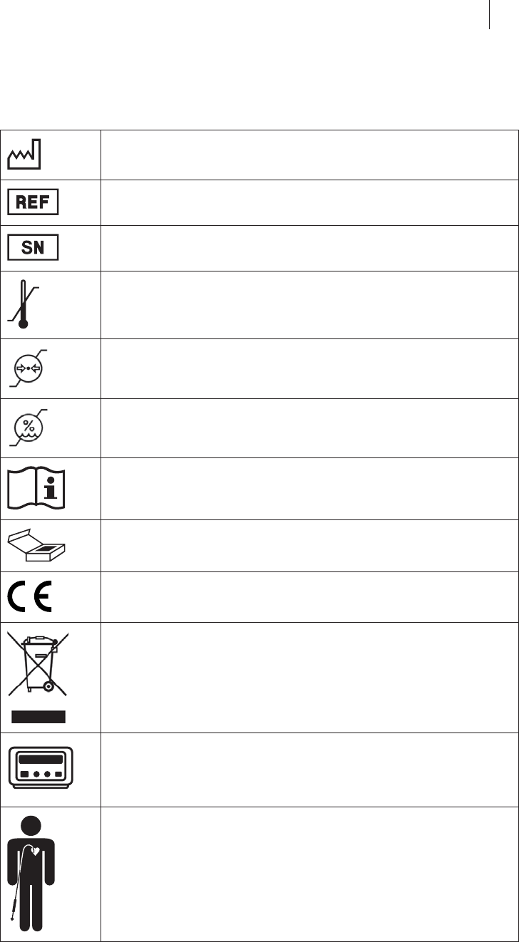
Legend for the Label
The label icons symbolize the following:
Manufacturing date
BIOTRONIK order number
Serial number
Temperature limit for storage
Air pressure limit for storage
Humidity limit for storage
Follow the instructions for use
Contents
CE mark
Device contains materials that must be correctly disposed of
in accordance with environmental protection regulations.
The European Directive 2012/19/EC regarding waste elec-
trical and electronic equipment (WEEE) applies.
Return devices that are no longer used to BIOTRONIK.
Qubic Force
Patient with inserted diagnostic or ablation catheter

42 Directories
6 Directories
Directories6418423Technical ManualQubic Force
Index
A
Ablation catheter
Connecting, 18
Accessories, 39
Ambient conditions, 9
C
Characteristics, 36
Cleaning, 11
Compatible RF generators, 2
Connecting
Ablation catheter, 18
External monitor, 21
Keyboard, 22
Mouse, 22
RF generator, 19
USB stick, 22
Connection
Power cord, 18
Contraindications, 2
D
Damage, 9
Device
Factory settings, 38
General description, 2
Overview, 14
Disinfection, 11
Disposal, 13
Disposal of cables, 13
E
Electromagnetic interference, 4
Electrostatic potentials, 8
Emergency equipment, 7
Expert knowledge, 4
Expertise, 3, 4
External monitor
Connecting, 21
F
Factory settings, 38
Fuse replacement, 13

Directories 43
G
Graphic display, 30
I
Inspection, 12
Installation location, 17
Intended medical use, 2
Intended use, 2
Interference
Electromagnetic, 4
Introduction, 2
K
Keyboard
Connecting, 22
Keys on the Device, 24
M
Main functions, 2
Main view, 26
Maintenance, 11
Inspection, 12
Test before each use, 12
Monitor port, 21
Mouse
Connecting, 22
N
Numerical display, 29
O
Operating conditions, 9
Overview, 2
P
Parameter values, 38
Patient group, 2
Potential equalization, 8
Power cord
Connect, 18
Power supply, 10
R
Range of values, 38
Redel port
Ablation catheter, 18
RF generator, 19
RF generator
Connecting, 19

44 Directories
S
Safety warnings
General, 7
Screen, 26
Set markers, 25
Status bar, 28
Sterilization, 12
Storage conditions, 9
Switching off, 23
Switching on, 23
Symbols
On the device, 16
Packaging, 41
T
TareSet to zeroSet values to zero, 24
Target group
Patients, 2
Technical manual, 3
Technical Data
Measurement accuracy, 38
Technical data, 36
Ambient conditions, 36
General classification, 36
Longevity, 36
Power cord port, 37
Safety equipment, 36
Technical details
Light source, 37
RFID communication, 37
Technical manual, 3
Transport conditions, 9
Transport damage, 9
Trend display, 32
U
USB port, 22
USB stick
Connecting, 22
V
View
Settings, 33

BIOTRONIK SE & o K
Woermannkehre 1
12359 Berln ermany
Tel +49 (0) 30 68905-0
Fax +49 (0) 30 6852804
salesbotronkcom
wwwbotronkcom
16-D-36
Revision: D (2016-08-22)
© BIOTRONIK SE & Co. KG
All rights reserved.
Specifications subject to modification,
revision and improvement.
® All product names in use may be trademarks
or registered trademarks held by BIOTRONIK
or the respective owner.
J
0123
2016
J
0681
2016