BIOTRONIK SE and KG RENAMIC Medical Programmer and Monitoring Device User Manual Renamic
BIOTRONIK SE & Co. KG Medical Programmer and Monitoring Device Renamic
UserManual.wiki
>
BIOTRONIK SE and KG
>
RENAMIC User Manual
QRIRENAMIC_UserMan
Navigation menu
Upload a User Manual
Namespaces
Wiki Guide
HTML
PDF
Info
Views
User Manual
Discussion / Help
Navigation
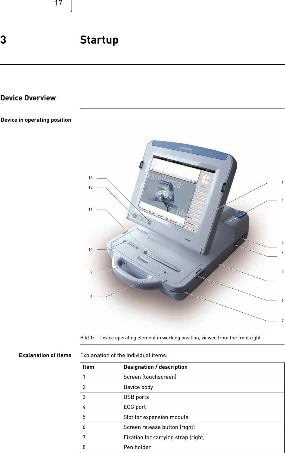
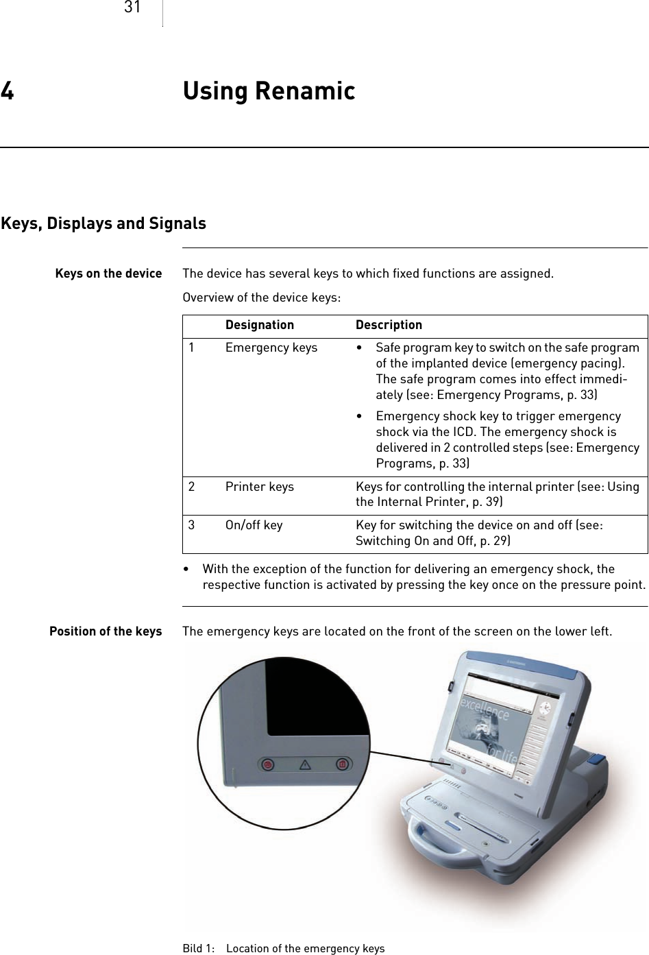
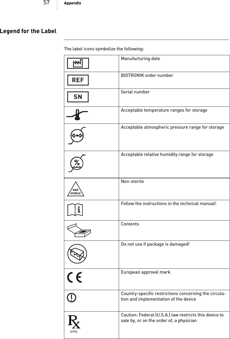
![33 Using RenamicEmergency ProgramsQUICK REFERENCE GUIDEFOR EMERGENCIESSAFE PROGRAM (EMERGENCY PACING): DELIVER EMERGENCY SHOCK: Purpose of the emergencybuttonsThe emergency buttons are used for the following: • They implement the parameters of the safe program (emergency pacing) by pressing a single button.• They start emergency pacing or emergency shock.Condition The programming head creates telemetry contact between Renamic and the active implanted device.Sequence When the emergency buttons are activated, the following will occur: • The current active programming in the implanted device will be deactivated.• The corresponding emergency parameter values will be activated and the selected emergency program will start.Step Action1 Position the PGH above the implanted device so that telemetry contact is created.2 Press the safe program button:Step Action1 Position the PGH above the ICD so that telemetry contact is created.2 Press the emergency shock button:3 In the dialog window, select [EMERGENCY SHOCK].WARNINGDanger to the patient from high electrical energiesHigh levels of electrical energy are conducted to the patient through the emer-gency programs.• Only activate the safe program or emergency shock under the supervision of a physician.](https://usermanual.wiki/BIOTRONIK-SE-and-KG/RENAMIC/User-Guide-1365092-Page-32.png)
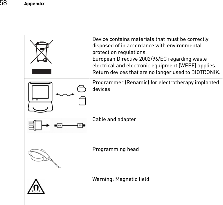
![34 Using RenamicLocation of the emergencybuttonsBild 3: Location of the emergency buttons on the deviceStart emergency pacing Proceed as follows: Stop emergency pacing Proceed as follows: Trigger emergency shock Proceed as follows: Step Action1 Position the PGH above the implanted device so that telemetry contact is created.2 Press the safe program button:Step Action1 Activate the desired permanent parameters in the program of the implanted device and transfer them to the implanted device.Step Action Result1 Position the PGH above the ICD so that telemetry contact is created.Telemetry contact is created between the ICD and the Renamic programmer. 2 Press the emergency shock button:• The emergency shock parameters are activated.• As a safety precaution, a dialog window will give you the option to cancel this action.3 In the dialog window, select [EMERGENCY SHOCK].• The ICD shock capacitors are charged.• Renamic triggers a 30 or 36 J emer-gency shock via the ICD.](https://usermanual.wiki/BIOTRONIK-SE-and-KG/RENAMIC/User-Guide-1365092-Page-33.png)
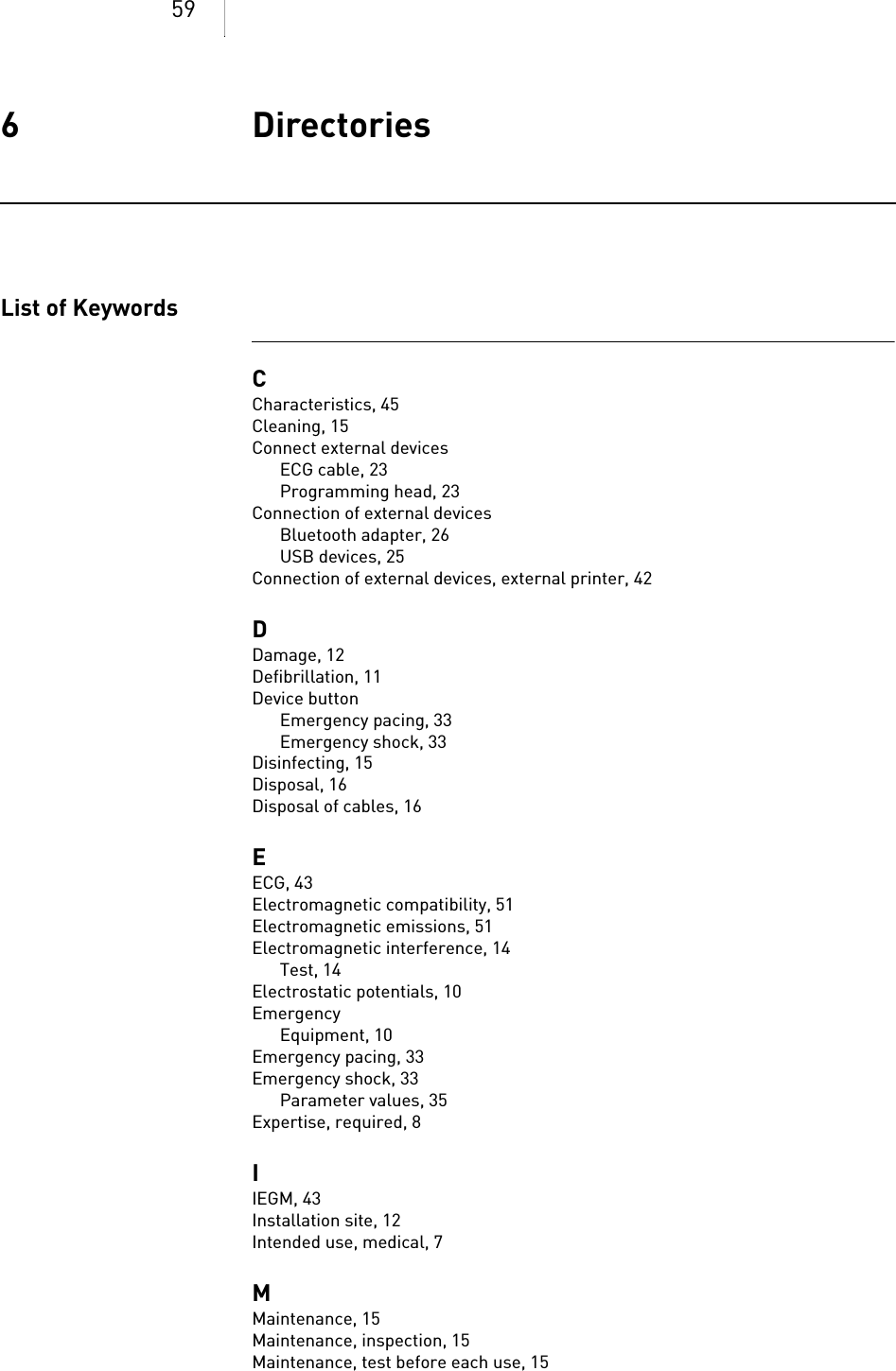
![47 AppendixInternal printerMICSGSM moduleUMTS moduleCategory DesignType Thermal printerPrinting width 4'Resolution 8 Dots/mmPaper Z-foldPaper format (B x L) 112 x 125 mmPaper supply 200 + 10 sheetsCategory DesignRate band 9 channels 402 – 405 MhzRange 300 kHzStandard channel 403.65 MHzModulation FSKEncoding ManchesterData rate 32768, 16384, 8192, 4096, 2048 bit/s (unencoded)Category DesignModel GSM/GPRS quadband MotorolaType G24L bzw. G24GSM rate 850 MHz, 900 MHz, 1800 MHz, 1900 MHzTransmission power 2 W: 850/900 MHz1 W: 1800/1900 MHzGPRS Multislot class 10(4 Down, 2 Up)Category DesignModel Motorola, 4 band GSM +3 band UMTSType H24UMTS rate 850 MHz, 1900 MHz, 2100 MHzGSM rate 850 MHz, 900 MHz, 1800 MHz, 1900 MHzUMTS transmission power 0,25 WGSM transmission power 2 W: 850/900 MHz1 W: 1800/1900 MHzUMTS Max. Range:Uplink: 5.76 MbpsDownlink: 7.2 MbpsUE CAT [1-8], 11, 12 supportedCompressed mode (3GPP TS25.212)GSM Multi-slot class 12(4 down, 4 up, 4 total)Coding scheme: CS1–CS4](https://usermanual.wiki/BIOTRONIK-SE-and-KG/RENAMIC/User-Guide-1365092-Page-46.png)
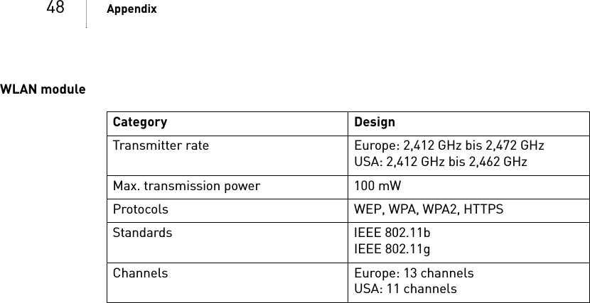
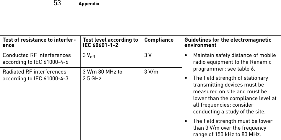
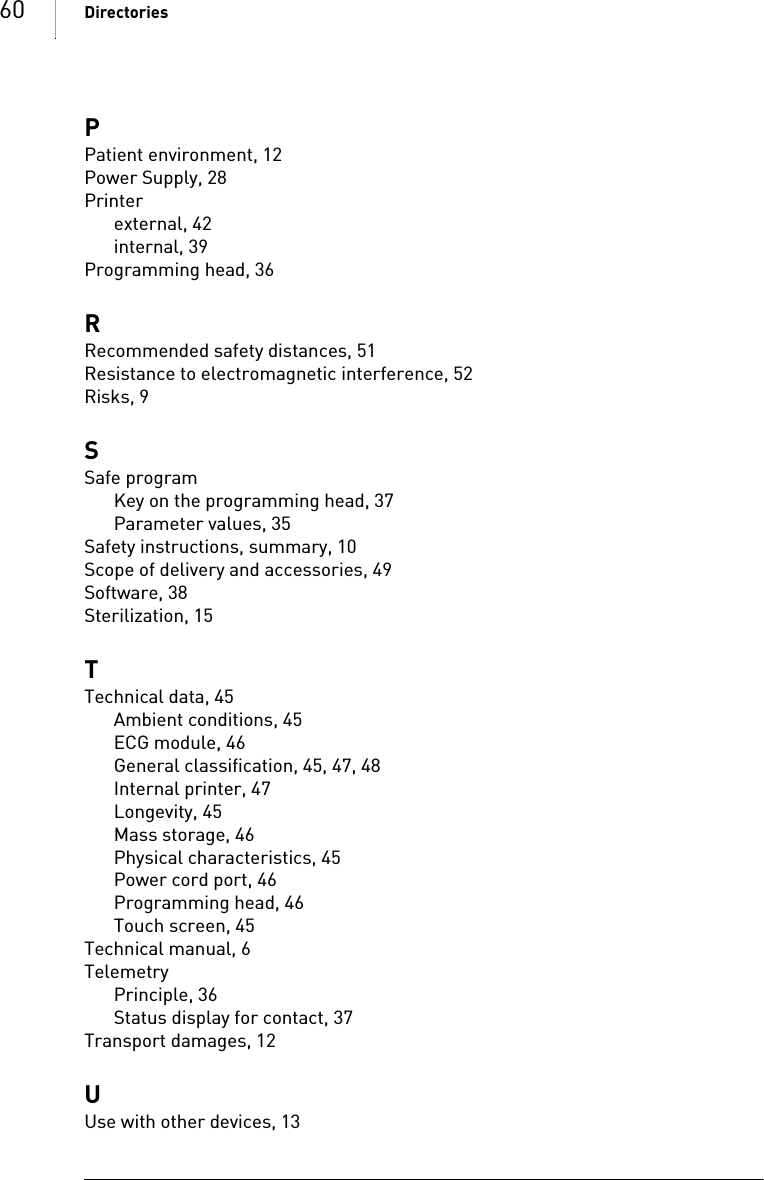
![51 AppendixElectromagnetic Compatibility in Compliance with EN 60601-1-2:2007• As the user, you must ensure that the device is operated in a suitable electro-magnetic environment. • The following guidelines may not be applicable in all cases. The propagation of electromagnetic values is, for example, affected by the absorption and reflec-tion of structures, objects and people. This data is for your personal informa-tion.Electromagnetic Emissions(Table 1)Recommended safetydistances (Table 6)• Safety distances help prevent interference if you maintain a minimum distance between transmitters such as mobile RF telecommunication devices and the Renamic programmer. The necessary distance depends on the respective power output of the transmitter.• For transmitters whose maximum output power is not indicated in the table, the recommended safety distance [d] can be calculated in meters using an equation that is suitable for the respective transmission frequency range. P is the Devices with the warning sign “Beware of non-ionizing radiation” must not be operated in the environment of the device due to poten-tial interferences.Measuring the emitted inter-ference Compliance Guidelines for the electromagnetic environmentRF interference according to CISPR 11Group 1 The device uses RF energy exclusively for its own function. Therefore, the RF interference emitted is very low and not likely to cause any interference in nearby electronic equip-ment.RF interference according to CISPR 11Class B The device is suitable for use in all establishments. This includes residences and facilities directly connected to the public power supply network that supplies buildings used for domestic purposes.Interference of harmonic oscil-lations according to IEC 61000-3-2Class AEmitted interference of voltage fluctuations according to IEC 61000-3-3CompliesNote: At 80 MHz and at 800 MHz, the higher frequency range applies.Transmission frequency 150 kHz to 80 MHz 80 MHz to 800 MHz 800 MHz to 2.5 GHzMaximum output power of the transmitter [W]Safety distance [m] 0.01 0.12 0.12 0.240.1 0.37 0.37 0.741 1.17 1.17 2.3410 3.70 3.70 7.40100 11.7 11.7 23.4](https://usermanual.wiki/BIOTRONIK-SE-and-KG/RENAMIC/User-Guide-1365092-Page-50.png)
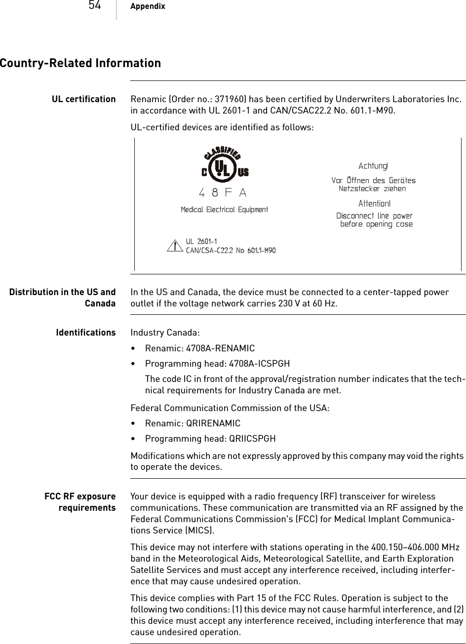
![52 Appendixmaximum output power of the transmitter in watts [W] according to the specifi-cation of the transmitter's manufacturer.Resistance to electromag-netic interference(tables 2 and 4)• When the measured field strength exceeds the specified compliance level at the operating location of the Renamic device, observe the device in order to deter-mine whether it is functioning properly.• If abnormal performance is observed, change the orientation or the location of the device. In the frequency range of 150 kHz to 80 MHz, ensure that field strengths are lower than 3 V/m.Transmission frequency 150 kHz to 80 MHz 80 MHz to 800 MHz 800 MHz to 2.5 GHzEquation d = 1.17 P d = 1.17 P d = 2.34 PNote: UT is the mains alternating voltage before applying the test levels.Test of resistance to interfer-ence Test level according to IEC 60601-1-2 Compliance Guidelines for the electromagnetic environmentElectrostatic discharge (ESD) according to IEC 61000-4-26 kV contact discharge8 kV air dischargeSame as test level• Operate the devices on floors made of wood, concrete, or ceramic tile. If the floor is covered with synthetic material, the relative humidity must be at least 30%.Fast transient electric interfer-ences (bursts) according to IEC 61000-4-42 kV for power supply lines1 kV for input and output linesSame as test level• Ensure that the power supply quality is that of a typical commer-cial and/or hospital environment.Surges according to IEC 61000-4-51kV push-pull voltage2 kV for common-mode voltageVoltage drops, brief interrup-tions and fluctuations in the supply voltage according to IEC 61000-4-15% UT for 1/2 cycle 95% drop40% UT for 5 cycles 60% drop70% UT for 25 cycles 30% drop5% UT for 5 s 95% dropSame as test level• Ensure that the power supply quality is that of a typical commer-cial and/or hospital environment. • If you require continued operation during power supply interruptions, connect the device to an uninter-ruptible power supply or use a battery for operation.Magnetic field at the supply frequencies (50/60 Hz) according to IEC 61000-4-83A/m Same as test level• Ensure that the magnetic field strengths are at levels character-istic of a location in a typical commercial and/or hospital envi-ronment.Note: At 80 MHz and at 800 MHz, the higher frequency range applies.](https://usermanual.wiki/BIOTRONIK-SE-and-KG/RENAMIC/User-Guide-1365092-Page-51.png)