BIOTRONIK SE and KG RENAMIC Medical Programmer and Monitoring Device User Manual Renamic
BIOTRONIK SE & Co. KG Medical Programmer and Monitoring Device Renamic
QRIRENAMIC_UserMan

3Table of Contents
Table of Contents
Table of Contents
Introduction . . . . . . . . . . . . . . . . . . . . . . . . . . . . . . . . . . . . . . . . . . . . . . . . . . 5
About the Device . . . . . . . . . . . . . . . . . . . . . . . . . . . . . . . . . . . 5
About this Technical Manual. . . . . . . . . . . . . . . . . . . . . . . . . . 6
Safety During Use . . . . . . . . . . . . . . . . . . . . . . . . . . . . . . . . . . . . . . . . . . . . . 7
Intended Medical Use . . . . . . . . . . . . . . . . . . . . . . . . . . . . . . . 7
Required Expertise . . . . . . . . . . . . . . . . . . . . . . . . . . . . . . . . . 8
Residual Risk . . . . . . . . . . . . . . . . . . . . . . . . . . . . . . . . . . . . . . 9
General Safety Instructions . . . . . . . . . . . . . . . . . . . . . . . . . 10
Operating Conditions . . . . . . . . . . . . . . . . . . . . . . . . . . . . . . . 12
Electromagnetic Interference. . . . . . . . . . . . . . . . . . . . . . . . 14
Maintenance, Care and Disposal . . . . . . . . . . . . . . . . . . . . . 15
Startup . . . . . . . . . . . . . . . . . . . . . . . . . . . . . . . . . . . . . . . . . . . . . . . . . . . . . 17
Device Overview . . . . . . . . . . . . . . . . . . . . . . . . . . . . . . . . . . . 17
Transportation and Setup . . . . . . . . . . . . . . . . . . . . . . . . . . . 21
Connections and Cables . . . . . . . . . . . . . . . . . . . . . . . . . . . . 23
Power Supply . . . . . . . . . . . . . . . . . . . . . . . . . . . . . . . . . . . . . 28
Switching On and Off . . . . . . . . . . . . . . . . . . . . . . . . . . . . . . . 29
Using Renamic . . . . . . . . . . . . . . . . . . . . . . . . . . . . . . . . . . . . . . . . . . . . . . . 31
Keys, Displays and Signals . . . . . . . . . . . . . . . . . . . . . . . . . . 31
Emergency Programs . . . . . . . . . . . . . . . . . . . . . . . . . . . . . . 33
Programming Head . . . . . . . . . . . . . . . . . . . . . . . . . . . . . . . . 36
Communication with Active Implanted Devices . . . . . . . . . 38
Using the Internal Printer . . . . . . . . . . . . . . . . . . . . . . . . . . . 39
Using an External Printer . . . . . . . . . . . . . . . . . . . . . . . . . . . 42
ECG and IEGM Functions. . . . . . . . . . . . . . . . . . . . . . . . . . . . 43
Appendix . . . . . . . . . . . . . . . . . . . . . . . . . . . . . . . . . . . . . . . . . . . . . . . . . . . . 45
Technical Data . . . . . . . . . . . . . . . . . . . . . . . . . . . . . . . . . . . . 45
Scope of Delivery and Accessories. . . . . . . . . . . . . . . . . . . . 49
Electromagnetic Compatibility in Compliance
with EN 60601-1-2:2007 . . . . . . . . . . . . . . . . . . . . . . . . . . . . 51
Country-Related Information . . . . . . . . . . . . . . . . . . . . . . . . 54
Symbols on the Components . . . . . . . . . . . . . . . . . . . . . . . . 55
Legend for the Label . . . . . . . . . . . . . . . . . . . . . . . . . . . . . . . 57
Directories . . . . . . . . . . . . . . . . . . . . . . . . . . . . . . . . . . . . . . . . . . . . . . . . . . 59
List of Keywords. . . . . . . . . . . . . . . . . . . . . . . . . . . . . . . . . . . 59
377213--D

4Table of Contents

5
1 Introduction
Introduction1xxxxxx--XDoc-classRenamic
About the Device
General description Renamic is a portable programmer and monitoring device.
According the customer specification the device is equipped with a GSM, UMTS or
WIFI module. This enables the direct export of patient data from Renamic to
hospital or practice networks.
It is used during the implantation procedure and follow-up of implantable pulse
generators and ICDs (implantable cardioverter-defibrillators).
Primary functions The device has the following primary functions:
Function Purpose
Programming and testing
functions
Program BIOTRONIK pacemakers and ICDs during
the implantation procedure or follow-ups
ECG recorder and ECG
monitor
Display and printout of up to three leads of surface
ECGs, as well as up to three intracardiac deriva-
tions (IEGMs) and the corresponding event
markers, in real-time
Data management Store parameter values and ECG/IEGM recordings
for computer-aided archiving and evaluation
Documentation Print out follow-up reports using the internal and/
or external printer

6Introduction
About this Technical Manual
Objective This technical manual provides the user with all the safety information required to
use the Renamic programmer.
The following topics are covered in this manual:
•Device startup
• Interrogation, testing and programming of implantable pulse generators and
cardioverter-defibrillators (ICD)
Target group This technical manual is intended for physicians and trained medical personnel
who are familiar with the following:
• The use of implantable pulse generators and ICDs
• The risks and possible complications associated of using these systems
Additional requirements include:
• Medical knowledge:
— Basic medical knowledge of the therapy applied
— Training in the handling and programming of implantable pulse generators
and ICDs
• Technical knowledge:
— Ability to work with a PC
— Ability to use software-controlled medical devices
Other technical manuals • Technical software manual for programming the intended implantable pulse
generator / ICD
• Technical manual for the intended implantable pulse generator / ICD

7
2 Safety During Use
Safety During Use2xxxxxx--XDoc-classRenamic
Intended Medical Use
Intended medical use The Renamic programmer provides communication with the implantable pulse
generator or ICD during the implantation procedure or follow-ups.
The Renamic programmer is intended to be used for the following tasks:
• Conduct sensing, pacing threshold and impedance tests
• Interrogate data of the implanted device such as program parameters,
recorded statistical data and episodes, as well as real-time IEGMs
• Display, printout, save and export data of the implanted device for analysis and
reporting purposes
• Transfer parameters to the implanted device

8Safety During Use
Required Expertise
Required expertise The programmer is intended for use by physicians and trained medical staff. Along
with their basic medical knowledge, a detailed knowledge of cardiac electrotherapy
is also required. Only qualified medical specialists with knowledge of cardiac elec-
trotherapy can properly operate the device.
German medical device
ordinance
This ordinance only applies in the Federal Republic of Germany. However, we
recommend that customers in other countries comply with this ordinance as well.
According to section 2, § 5, operation and use:
'The user may operate a (...) listed medical product only after the manufacturer or
the authorized agent who acts on behalf of the manufacturer has performed the
following requirements:
• 1. Checked the functionality of this medical product at the location where the
device will be used.
• 2. Trained the staff appointed by the user to correctly handle, use and operate
the medical product. This training must include handling, using and operating
the product in conjunction with other medical products, implements and acces-
sories in accordance with the technical manual, as well as any applicable
safety-related information and maintenance instructions.
(...)
(3) Proof of a functional test have been performed as stated in Paragraph 1 Item 1,
and the training record of the staff appointed by the user, discussed in Paragraph 1
Item 2, are to be documented.'

9Safety During Use
Residual Risk
Risk analysis The risk analysis carried out by the manufacturer's Risk Management Team has
determined that the residual risk is as low as reasonably possible.
It is a prerequisite that the programmer has been serviced and inspected according
to the manufacturer's specifications by qualified medical staff and in compliance
with the safety-relevant instructions in this technical manual.

10 Safety During Use
General Safety Instructions
Technical manual Only use the programmer in accordance with this technical manual.
Risks of improper handling Disregarding the safety instructions can endanger the patient, the staff and the
equipment.
The following dangers may arise in the event of improper use:
• Failure of important device functions
• Personal endangerment due to electrical effects
Changes not permitted Only the manufacturer or a party expressly authorized by BIOTRONIK may perform
corrective maintenance, enhancements or modifications to the device.
Replacement parts and
accessories
To ensure safety compliance, use only original replacement parts and accessories
authorized by BIOTRONIK. Using any other parts voids the manufacturer's liability
for any consequences, guarantee and warranty.
Defects Do not use defective or damaged devices.
Physician supervision The device should only be used under the constant supervision of a physician.
During operation of the device, it is necessary to monitor the patient’s heart rate
and ensure that for each stimulation, the display of events and their results (using
an external ECG monitor) is plausible.
Patient observation Ensure that patients are individually observed over a suitable period of time in
order to monitor the compatibility and effectiveness of parameter combinations.
Emergency equipment Always ensure that in the event of an emergency the following basic equipment is
available:
•Defibrillator
• Intubation set
•Oxygen
•Emergency drugs
For pacemaker-dependent patients, an additional external pacemaker must also
be available.
Life support system Do not use this device as a life support system.
Liquids • Never use a damp or wet device.
• Protect the device from the accidental ingression of fluids (e.g. infusion fluids).
Electrostatic potentials Ensure that electrostatic potentials between medical staff and patients are
balanced. Before handling the device, the electrostatic potential between the
doctor or medical staff and the patient must be balanced by touching the patient at
a point as far away from the leads as possible.
Note: Failure to observe the safety precautions voids all damage claims and
manufacturer liability.

11 Safety During Use
External ECG device During the implantation procedure, the patient's heart rate should be additionally
monitored using an ECG monitor or ECG recorder.
Defibrillation • When connected with the authorized ECG cable, the device is protected against
defibrillation energy. Following a defibrillation, check all functions of the
programmer.
• During defibrillation, do not touch the patient, the programmer the patient is
connected to or the attached accessories. Otherwise, there is a danger that you
may suffer an electrical shock.

12 Safety During Use
Operating Conditions
Storage and transportation • If the packaging is damaged, please contact BIOTRONIK immediately. Do not
put the device into operation.
Installation site Only operate the device in rooms that fulfill the following conditions:
• No danger of explosion
• Suitable for medical purposes
• Class I power outlet with protection cable connection
Place the device on a flat, dry surface. It should be placed so that it can not slip even
with the cable connected and so that the patient can only come into contact with the
applied parts, namely the programming head and ECG cable.
Power supply The device is operated via the 230 V / 50 Hz or 115 V / 60 Hz AC current of a room
used for medical purposes. The electrical port must fulfill the following conditions:
• The network installation fulfills at least the requirements of IEC 60364-7-
710:2002 group 1.
• The device cable feeds directly into a permanently installed socket. No portable
power strips are connected in between.
• When used in combination with other devices, no portable multiple socket
outlets should be used.
• Only those power connection cables can be used which are suitable for medical
devices, e.g. BIOTRONIK power cords (see Accessories, p. 49) or power cords of
equal value labeled H05VV 3 x 0.75 mm, H05VV 3 x 1 mm or SJT AWG18.
Cable and plug connections • Replace any cable that shows even slight damage.
• Lay all cables between the patient and the device, as well as within the
measuring apparatus, in such a way that they pose no danger of tripping over
them and that any tensile forces that may occur can be safely buffered.
• As a general rule, cables should only be connected or disconnected when the
device is switched off, unless expressly permitted in the corresponding section
of this technical manual.
• Ensure that the contacts of all connections and plugs are clean. Soiled contacts
can lead to signal distortions, and thus to false diagnoses.
• Ensure that there is no condensation on the plugs or in the connector ports. If
condensation is present, dry it before use.
• Do not force plugs into the connector ports and when disconnecting the plugs,
do not pull on the cable to release the lock.
• All lead connections are swap-safe and encoded at the lead connectors.
Patient environment This device may be used in the patient environment.
CAUTION
Functional impairment due to external damage
Mechanical impact, for example dropping the unit - even from a height of over 5
cm if unpackaged - can permanently impair the function of the system.
• Do not use the device if it shows visible damage.
• Contact BIOTRONIK for testing and, if necessary, repair of the equipment.

13 Safety During Use
Place the device on a flat, dry surface so that the patient can only come into contact
with the applied parts, namely the programming head and ECG cable.
The physician must not touch any connections such as USB ports or interfaces for
modules or the programming head and the patient at the same time.
Use with other devices The device may not be used on the patient in conjunction with high frequency
surgical equipment.
Start parameters and
default settings
Once switched on, the device functions according to BIOTRONIK's default settings
or the user-defined start parameters.
Note: In addition to BIOTRONIK's default start parameters, the user-defined start
parameters can also be saved and recalled.

14 Safety During Use
Electromagnetic Interference
Possible electromagnetic
interference
The programmer is protected from disturbances resulting from electromagnetic
interference, electrostatic discharges and other sources, including interference
from cables. Simultaneously, the emitted interference has been reduced to a
minimum. Thus the programmer conforms to the requirements of EN 60601-1-2
(in its valid form at the time of delivery).
However, strong electromagnetic interferences that occur in the close vicinity of
electrical motors, power cables, PCs, monitors, or other – possibly defective – elec-
trical devices may compromise the function of the programmer in certain cases.
This kind of device malfunction should be considered if the following is observed:
• The device switches on by itself.
• The device senses false intrinsic events in the ECG, IEGM or marker channel
(artifacts).
• The device displays other inexplicable functions.
Correct operation of the device can be restored with the following:
• Switch off the malfunctioning electronic device.
• Remove the source of interference from the device.
• Switch the programmer on and off or break the electrical connection between
the device and the source of the interference as much as possible without
causing any danger.
If the interference continues, contact BIOTRONIK immediately.
EMI test The telemetry between the programming head and the implanted device can be
impaired by electromagnetic interference (EMI). This can be observed when it
becomes difficult or even impossible to interrogate or program the implanted
device. Using the EMI test (refer to device software help), the source of the electro-
magnetic interference can be located and then turned off.
Note: If accessories other than those specified by BIOTRONIK are used,
increased interference or lower resistance to interference can be expected.
Note: If accessories specified by BIOTRONIK are used on other devices,
increased interference or lower resistance to interference can be expected.
Note: Portable radio communication devices can interfere with the programmer
functioning.
15 Safety During Use
Maintenance, Care and Disposal
The following regulations are valid for the device.
Cleaning and disinfecting • Use lint-free, soft cloths.
• Clean the housing with a damp cloth and mild soap solution or 70% isopro-
panol.
Disinfect with alcohol or aldehyde-based agents such as Aerodesin 2000,
Fugaten spray, Lysoformin 2000 or Aldasan 2000.
• Vacuum the ventilation slots regularly.
• Visually inspect the connections: make sure that the contacts for all connec-
tions and cables are clean and free of any type of dirt.
• To disinfect the patient cable and patient adapter, use a mixture of 70% isopro-
panol and 30% water oder Lysoformin 3000: Allow it to take effect for 15
minutes at 2% concentration.
Sterilization • The device cannot be sterilized.
Test before each use • A short test of the device and the approved accessories should be performed
prior to each use. This test consists of the following visual inspections and a
simple functional tests:
— Inspect the housing for mechanical damage, dents, loose parts, cracks, etc.
— Inspect cables and connection areas to ensure proper insulation, no breaks,
etc.
— Inspect that the stylus is in place
— Inspect the labeling for legibility
— Inspect the displays (e.g. time and date)
— Simple electrical function test: switch the device on; an internal function
test will be conducted automatically
— If no error message appears, then no errors were found and the device can
be used
WARNING
Exposure to fluids may result in fatal injury
Before cleaning and disinfecting device surfaces: Pull the power plug!
CAUTION
Danger of explosion if exposed to cleaning and disinfecting agents
Let cleaning and disinfection agents evaporate before operating the device.
CAUTION
May be damaged by cleaning agents
Strong and abrasive cleaning agents and other organic solvents, such as ether or
benzine, corrode the surface of the device and must not be used.
16 Safety During Use
Inspection The inspection consists of the regular safety inspection according to medical device
standards. This ensures the safety of the device.
• The inspection must be performed
— After using in conjunction with high-frequency surgical instruments or
defibrillators
— If malfunctions are suspected
— Once a year
• This inspection can be performed by BIOTRONIK.
• The inspection should conform with the manufacturer specifications. These are
available upon request. The specifications list all necessary test steps and the
necessary equipment.
Changing a fuse The fuses are located above the power cord port in a fuse holder.
Disposal • This device contains materials that must be correctly disposed of in accordance
with environmental protection regulations. The European Directive 2002/96/EC
regarding waste electrical and electronic equipment (WEEE) applies.
• The symbol on the label – a crossed out garbage can – indicates that the device
must be disposed of in accordance with the WEEE directive. The black bar indi-
cates that the device was sold after the national implementation of the WEEE
directive was enforced in your country.
• Return devices that are no longer used to BIOTRONIK.
Disposal of cables
Non-contaminated cables must be disposed of in accordance with the European
Directive 2002/96/EC regarding waste electrical and electronic equipment (WEEE).
CAUTION
Mains voltage - risk of death from electric shock
Before changing the fuses, switch off the device and disconnect the power cord.
CAUTION
Risk of death from electric shock
Defective fuses may indicate a technical defect in the device.
Conduct an inspection after changing fuses and before resuming operation of the
device (see Inspection, p. 16).
Step Action
1 To unlock the fuse holder, push the latches on the right and left
inwards together.
2 Pull the fuse holder out.
3 Replace the old fuses with new ones of the same type (see Power
cord port, p. 46).
4 Re-insert the fuse holder and ensure that it locks securely in
place.
Note: Cables to be disposed of due to contact with blood must be disposed of as
medical waste, in accordance with environmental regulations.
17
3Startup
Startup3xxxxxx--XDoc-classRenamic
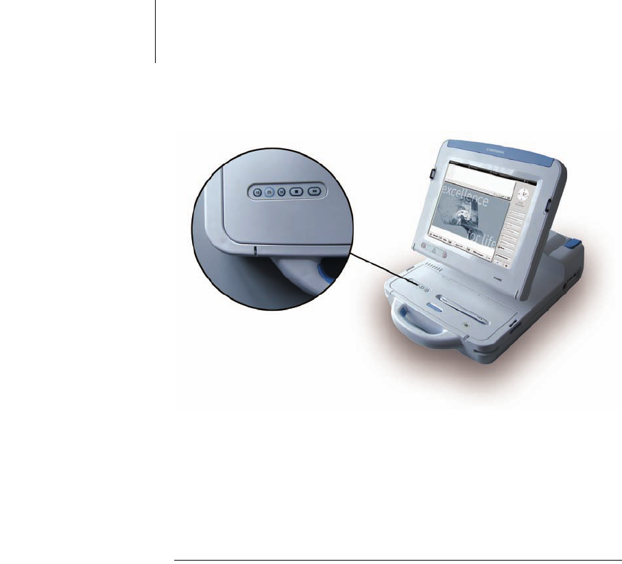
Device Overview
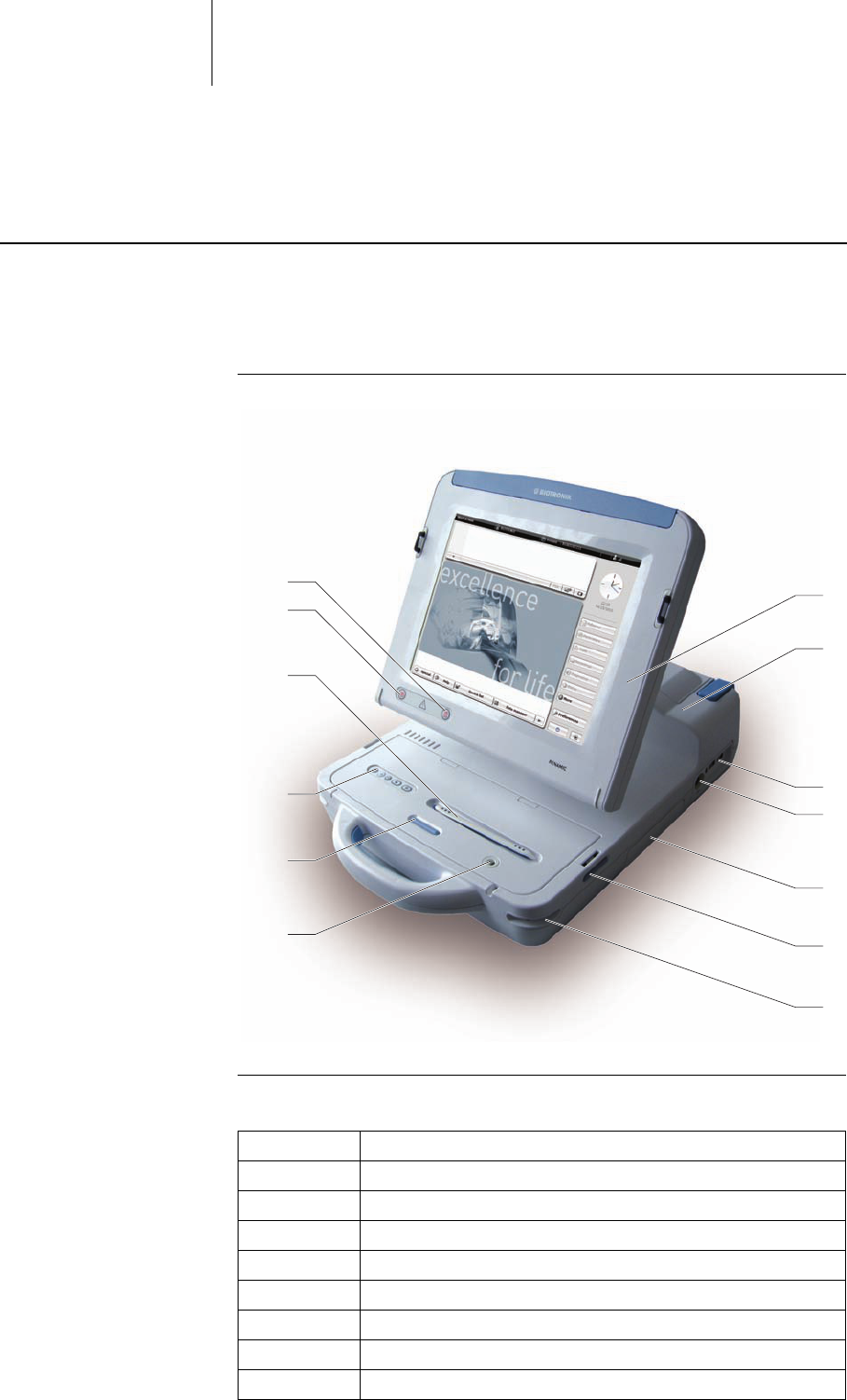
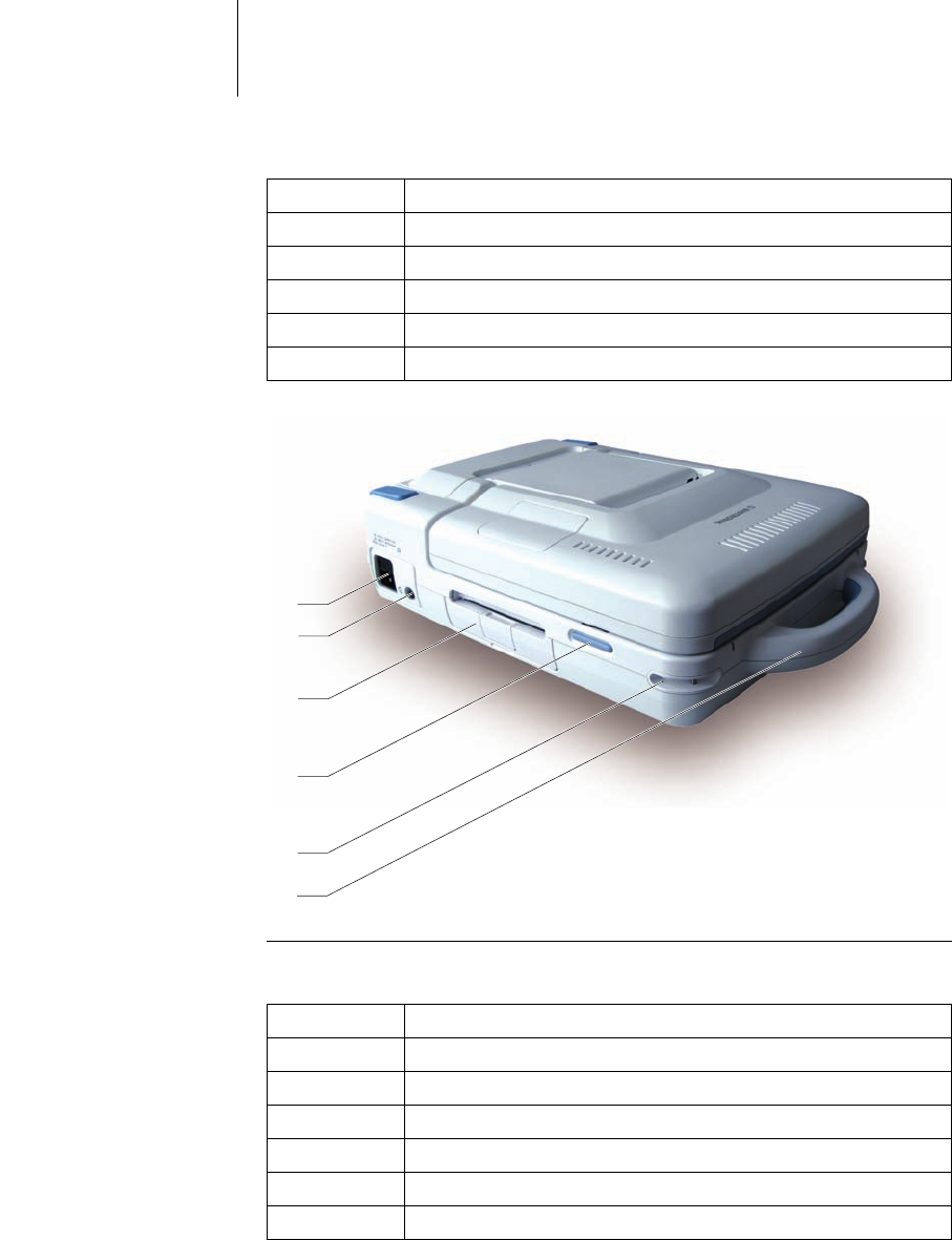
Device in operating position
Bild 1: Device operating element in working position, viewed from the front right
Explanation of items Explanation of the individual items:
7
1
2
3
4
5
6
8
13
12
11
10
9
Item Designation / description
1 Screen (touchscreen)
2 Device body
3USB ports
4ECG port
5 Slot for expansion module
6 Screen release button (right)
7 Fixation for carrying strap (right)
8 Pen holder
18 Startup
Device in transport position
Bild 2: Device operating element in transport position, viewed from the front left
Explanation of items Explanation of the individual items:
9 PGH compartment lid release button
10 Printer buttons
11 Stylus in pen holder
12 Safe program button
13 Emergency shock button
Item Designation / description
14
15
16
18
19
20
Item Designation / description
14 Carrying handle
15 Fixation for carrying strap (left)
16 Screen release button (left)
18 Paper tray for internal printer
19 On/off button
20 Power cord port and device fuse
19 Startup
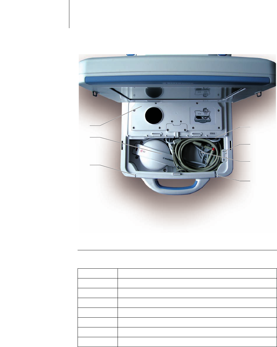
PGH compartment
Bild 3: Device operating elements, PGH compartment with lid open, viewed from above/in
front
Explanation of items Explanation of the individual items:
21
22
23
24
27
26
25
Item Designation / description
21 PGH port
22 USB slot for Bluetooth USB adapter
23 PGH cable and ECG cable
24 Cable feedthrough for PGH cable
25 On/off LED
26 Programming head (PGH)
27 PGH compartment lid
20 Startup
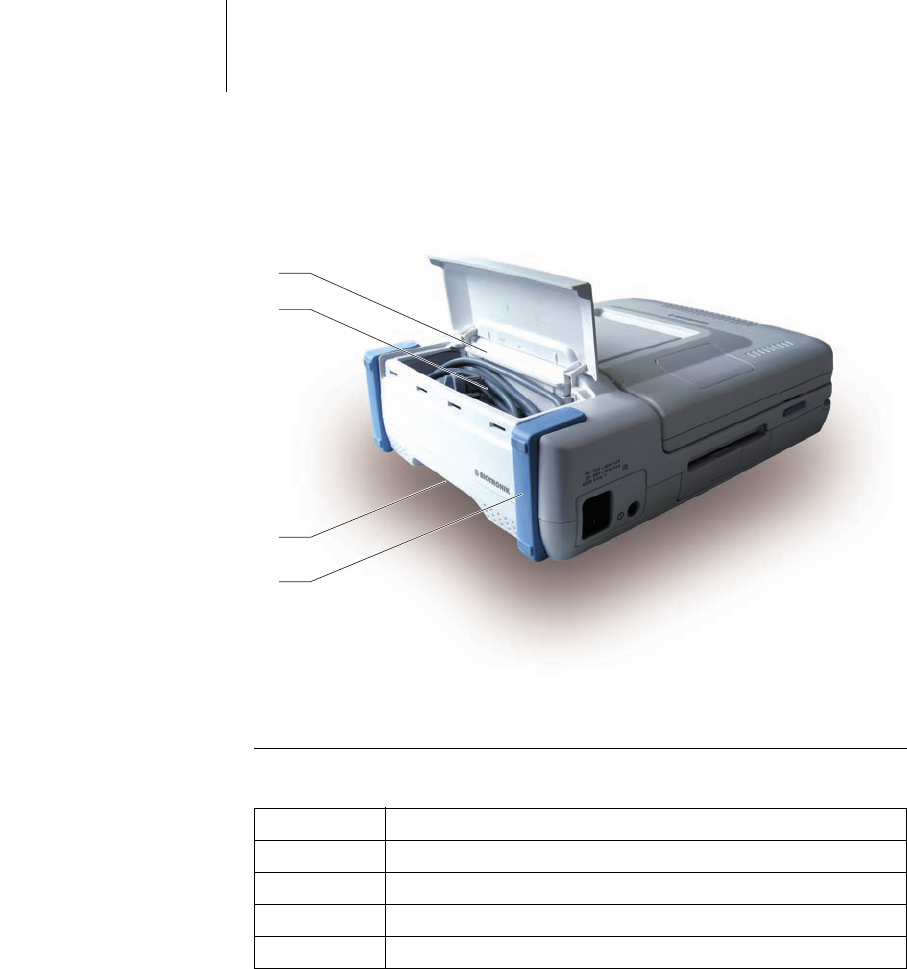
Power cord storage
compartment
Bild 4: Device operating elements, power cord storage compartment with lid open, viewed
from above/behind
Explanation of items Explanation of the individual items:
28
29
31
30
Item Designation / description
28 Anti-slip stand
29 Gripping tab
30 Power cord in power cord storage compartment
31 Power cord compartment lid
21 Startup
Transportation and Setup
Transporting the device • Renamic has an integrated ergonomic handle in the front and a gripping tab in
the back, which can be used to safely transport the device in any position.
• A carrying strap can also be attached to the device.
• The specially designed anti-slip pads allow for horizontal or vertical positioning
of the device.
• When the device is slightly lifted (using the handle), the slick corners of the base
allow for easy positioning on smooth surfaces (tables, shelves).
• After setting the device down, the anti-slip pads keep the device securely in
place.
Setting up the device
• Place the device on a flat dry surface. Make sure that it cannot shift even with
the cable connected and that the patient can only come into contact with the
applied parts, namely the programming head and ECG cable. The physician
must not touch any connections such as USB ports or interfaces for modules or
the programming head and the patient at the same time.
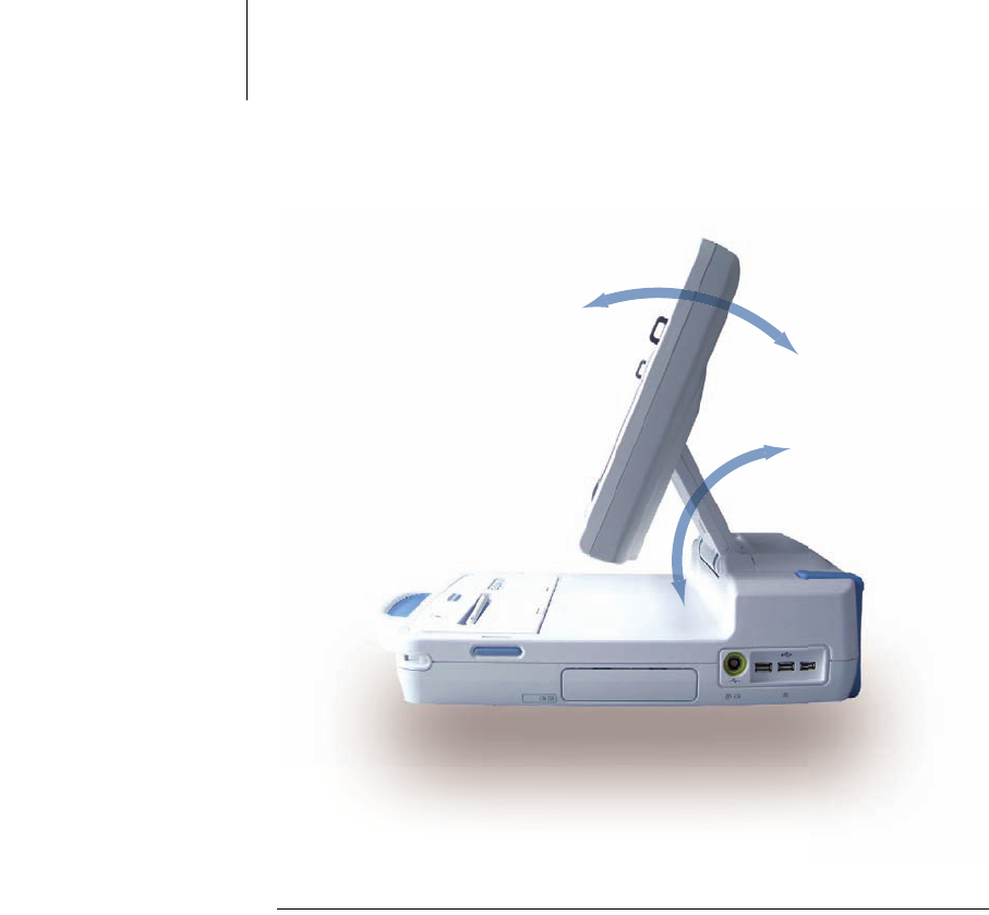
Tilting the screen up • In transport position (screen closed), unlock the screen by pressing both
release buttons at the same time. You can hear and feel the device unlock.
• Hold the sides of the screen with both hands and tilt it up to the position you
would like to use it in (1).
• Pivot the screen around the upper end of the screen arm (2.). The operating
position can be smoothly adjusted as needed.
The screen will remain in any position due to its self-retaining bearings.
WARNING
Danger to the user
Danger of tripping over connected cables during device transport.
• Prior to transporting the device, remove the attached cables and store them
in the compartments intended for this purpose.
WARNING
Danger to the patient
The device is not sterile and cannot be sterilized.
• Do not set up the device in a sterile area and do not position the device so that
the fan blows air into a sterile area.
Note: The device can be operated in the patient's environment.
22 Startup
The two hinges of the screen arm allow for a wide range of working positions.
Bild 5: Tilt radius of the screen and screen arm
1.1.
2.2.
23 Startup
Connections and Cables
Basic notes for cables and
connections
Connect programming head The PGH port is located at the top right of the device inside the PGH compartment.
Refer to figure PGH compartment, p. 19, item #21.
• Pull the short end of the cable out of the PGH compartment and connect the
PGH cable to the device PGH port.
• Feed the PGH cable through the PGH compartment cable feedthrough. Refer to
figure PGH compartment, p. 19, item #24.
Connect ECG cable
Note: Do not force the plugs into the ports. When disconnecting plugs, do not pull
on the cable.
Note: Only connect external devices that conform to DIN EN 60601 or DIN EN
60950 standards. Only then is the faultless functioning of the device guaranteed.
CAUTION
Allergic reactions and inflammations
Prevent the cable and programming head from coming into contact with the
patient's wounds or skin.
Note: Since the device remains ready for operation in the transport position
(screen flipped down and locked), the programming head can remain connected
while the device is in this position.
WARNING
Danger to patient by damaged cables
Damaged cables are limited in functionality and pose a danger to patients.
• Do not use damaged cables.
WARNING
Danger to the patient
Electrostatic potential differences can cause currents that are dangerous to the
patient.
• Balance possible differences in electrostatic potential with the patient by
touching the patient with your hand at a point a safe distance from the leads.
24 Startup
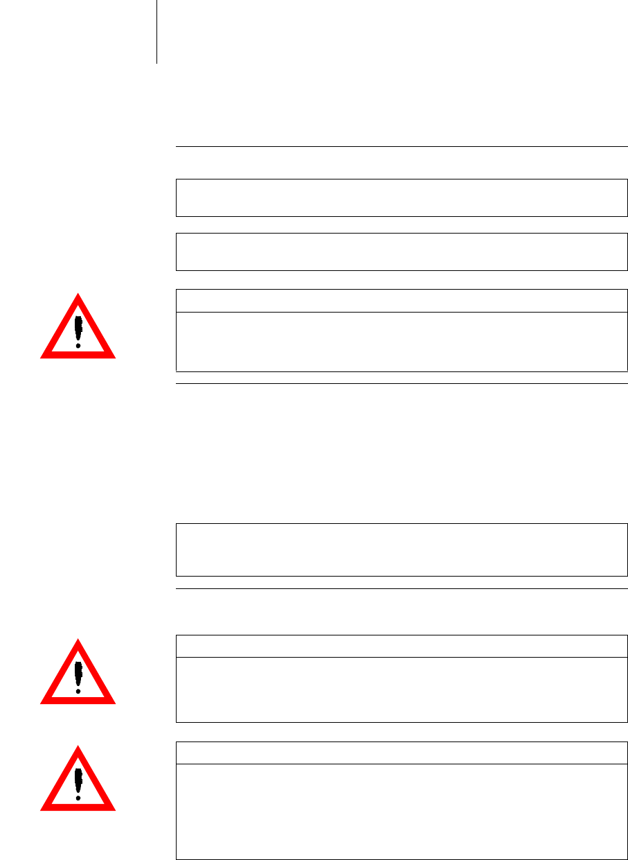
Renamic can be used with the PK-222 ECG cable:
Bild 6: ECG cable PK-222 with banana plugs for extremity leads (Einthoven)
The ECG cable PK-222 has
• Device: Redel plug, P series, 14-pole, 40°coded
• Patient: 4 color-coded banana plugs
WARNING
Danger to the patient or user from electrical currents in surface ECG leads
Electrical energy that flows into surface ECG leads can cause injuries to the skin
or cause an arrhythmia.
• The plugs of the ECG cables must not touch any conductive or grounded
components, nor should they be inserted in electrical outlets or other
connectors.
• Attach all PK-222 plugs on the patient end securely to the patient.
• Attach all unused plugs (e.g. if not all of the surface ECG connections are
used) securely to the patient.
WARNING
Danger to patient from allergic reactions
If the cable comes into contact with open wounds, it can cause allergic reactions.
• Prevent the cable from coming into contact with open wounds.
WARNING
Danger from loss of function
Damp cables have limited functionality and pose a danger to patients.
• Do not use damp cables.
WARNING
Danger from electrical currents
Unused cable contacts can conduct electrical currents to patients.
• Adhere unused cable contacts close to the patient.
Note: The ECG port can be disconnected and reconnected while the device is still
active.
Note: The PK-222 ECG cable is provided unsterile and cannot be sterilized.
Follow the instructions on cleaning and disinfecting in section Maintenance, Care
and Disposal, p. 15.
25 Startup
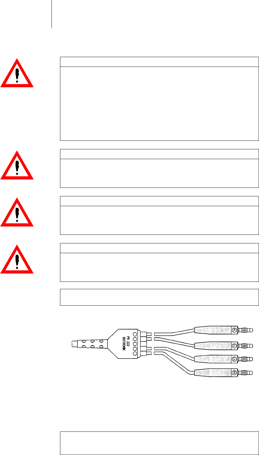
The ECG port is located on the back right of the device.
Bild 7: Position of the ECG port
• Connect the ECG cable to the ECG port.
Connection of USB devices The device's USB ports are intended for connection to various compatible devices,
e.g. a USB flash memory stick, an adapter for an external monitor or an adapter for
a serial interface.
Note: Cables to be disposed of due to contact with blood must be disposed of as
medical waste in accordance with environmental regulations.
Note: Information regarding approved adhesive and clamp leads for surface ECG
electrodes can be found in section Optional accessories (compatibility with third
party suppliers), p. 50.
Note: The USB flash drive used for data transfers must meet the Microsoft Blue-
tooth Stack standard.
Note: The USB port can be disconnected and reconnected while the device is still
active.
WARNING
Danger to the user when connecting non-conforming USB accessories.
Leakage currents can cause injuries to the skin or cause an arrhythmia.
• When using in combination with other devices, do not use portable multiple
socket outlets, but connect all devices to fixed outlets in the same electrical
circuit used for medical purposes.
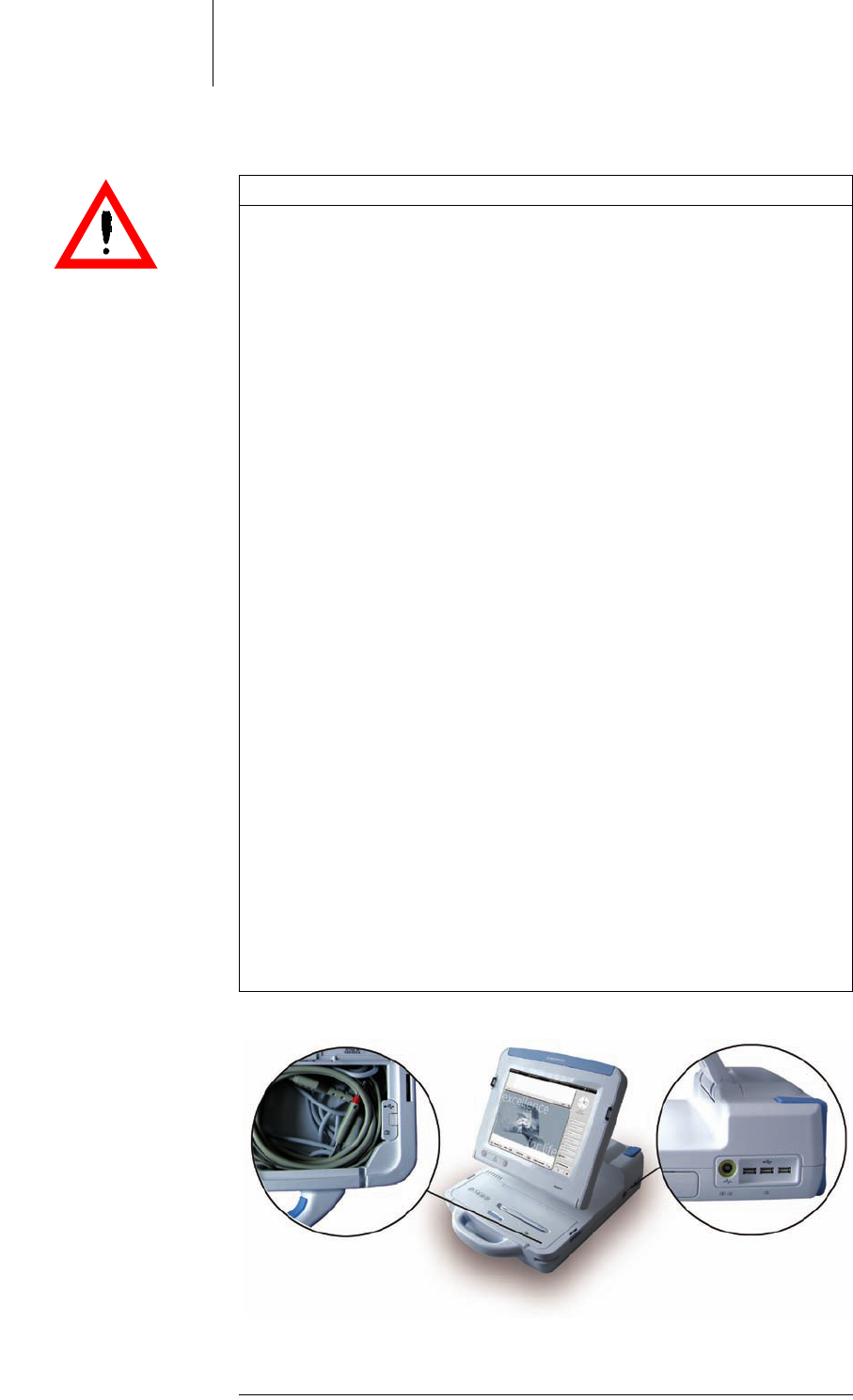
26 Startup
There are three USB ports located on the back right of the device and one in the
PGH compartment (recommended USB port for the Bluetooth adapter).
Bild 8: Position of the USB ports
• Connect the USB device or USB cable to the USB port.
CAUTION
Risk of exceeding the leakage currents when connecting external devices with
their own power supply or an electrically conductive connection to other
devices.
• Only connect devices that comply with the applicable ISO, EN or IEC standards
such as IEC 60601-1 or IEC 60950.
• Place devices that do not adhere to the IEC 60601-1 standard at least 1.5 m
away from the patient.
• Before initial commissioning, check and document all device combinations
according to IEC 60601-1 paragraph 16.6 for observance of leakage currents.
You do not have to perform this inspection if the USB device is supplied via
bus, which means it does not have its own power supply and has no electri-
cally conductive connection to other devices or if it is connected to Renamic's
USB port via an isolating separator (IEC 60601-1 paragraph 16.5) with a
dialectric strength of at least 1.5 kV (e.g. isolating USB hub model UISOHUB4
made by B&B electronics).
• Perform this inspection at least once per year according to the legal require-
ments.
• Ensure that the leakage currents do not exceed the following maximum
values when operating the device within the patient environment:
• Housing leakage current
Normal condition: 0.1 mA
Single fault condition: 1.5 mA
• Ground leakage current
Normal condition: 0.5 mA
Single fault condition: 1.0 mA
• Patient leakage current
Normal condition: 0.01 mA= / 0.1 mA ˜
Single fault condition: 0.05 mA= / 0.5 mA ˜
• Patient auxiliary current
Normal condition: 0.01 mA= / 0.1 mA ˜
Single fault condition: 0.05 mA= / 0.5 mA ˜

27 Startup
Equipping the device with a
Bluetooth adapter
If you equip the device with a Bluetooth adapter, various Bluetooth compatible
devices can communicate wirelessly with the programmer.
BIOTRONIK supplies a compatible Bluetooth adapter with the programmer.
• Before using the Bluetooth adapter, ensure that it is authorized for Bluetooth
radio communication in your respective country / region.
The recommended port for this Bluetooth adapter is located in the PGH compart-
ment on the right hand side of the device underneath the protective cap. Refer to
figure PGH compartment, p. 19, item #22.
We recommend connecting the Bluetooth adapter while the device is turned off.
• Open the PGH compartment and remove the protective cap from the port for the
Bluetooth adapter.
• Connect the Bluetooth adapter to the USB port.
• Replace the protective cap over the Bluetooth adapter.
28 Startup
Power Supply
Power supply The device is operated via the AC voltage of a room used for medical purposes:
• 100 – 115 V 10% / 60 Hz / 1.2 A / AC
• 220 – 230 V 10% / 50 Hz / 0.6 A / AC
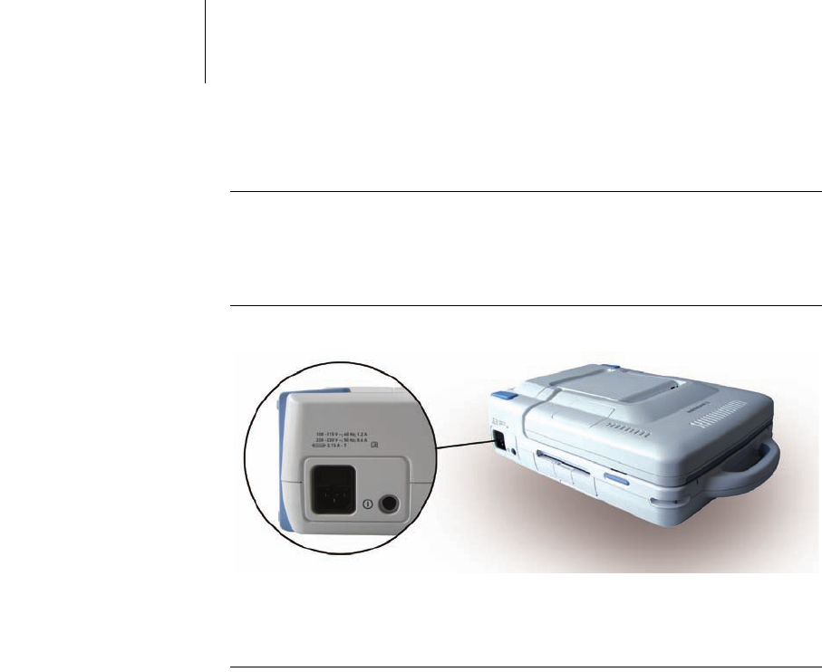
Connecting the power cord
to the device
The connection for the power supply is located on the back of the device on the left.
Bild 9: Position of the power cord port
• Connect the provided power cord to the device's power cord port and then to a
suitable power outlet.
29 Startup
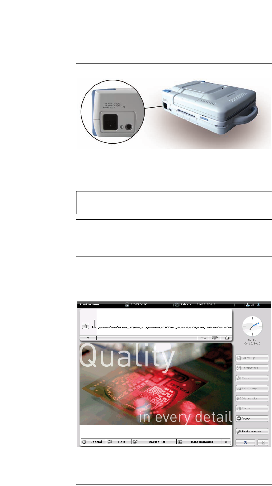
Switching On and Off
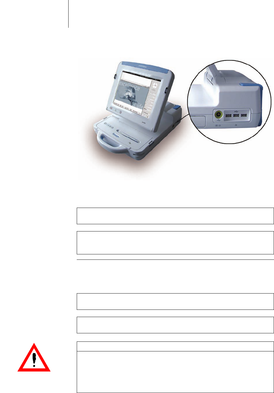
Switching the device on The on/off button is located on the back left of the device.
Bild 10: The on/off button is positioned next to the power cord port.
• To switch the device on, press the on/off button once on the pressure point.
• The on/off LED on the front left of the device lights up.
For the position of the on/off LED: refer toPGH compartment, p. 19, item #25.
Startup of the operating
system
After switching the device on, the operating system will boot.
During this time, the device cannot be operated.
Meanwhile, the start screen will also load.
Ready-for-service status,
start screen
After successful booting of the operating system, the screen displays the complete
start screen which indicates the device's ready-for-service status.
Depending on whether a programming head is connected, the device has telemetry
contact to an active implanted device and/or which other ports are occupied, then
the start screen may display additional details.
Bild 11: Start screen after successful booting of the operating system
•Check all displays and signals at all times for correct functionality. If a display
does not function correctly, then look for the cause. If necessary, switch the
device off and then on again.
Note: The device can be switched on in both the working position (screen open)
and in the transport positions (closed).
The on/off LED is visible in both positions.
30 Startup
Switching the device off • To switch the device off, press the on/off button once on the pressure point or
shut the device down using the software user interface.
CAUTION
Danger to data integrity
Sudden disconnection from the power source can lead to the corruption of data
• Only use the on/off button of the software user interface menu to switch the
device off.
Note: The device does not switch off if you close the screen.
Therefore, the device can be left in operating mode and put aside temporarily to
save space. Pay attention to the connected cables.
By reopening the screen, the programmer is immediately functional again.
31
4 Using Renamic
Using Renamic4xxxxxx--XDoc-classRenamic
Keys, Displays and Signals
Keys on the device The device has several keys to which fixed functions are assigned.
Overview of the device keys:
• With the exception of the function for delivering an emergency shock, the
respective function is activated by pressing the key once on the pressure point.
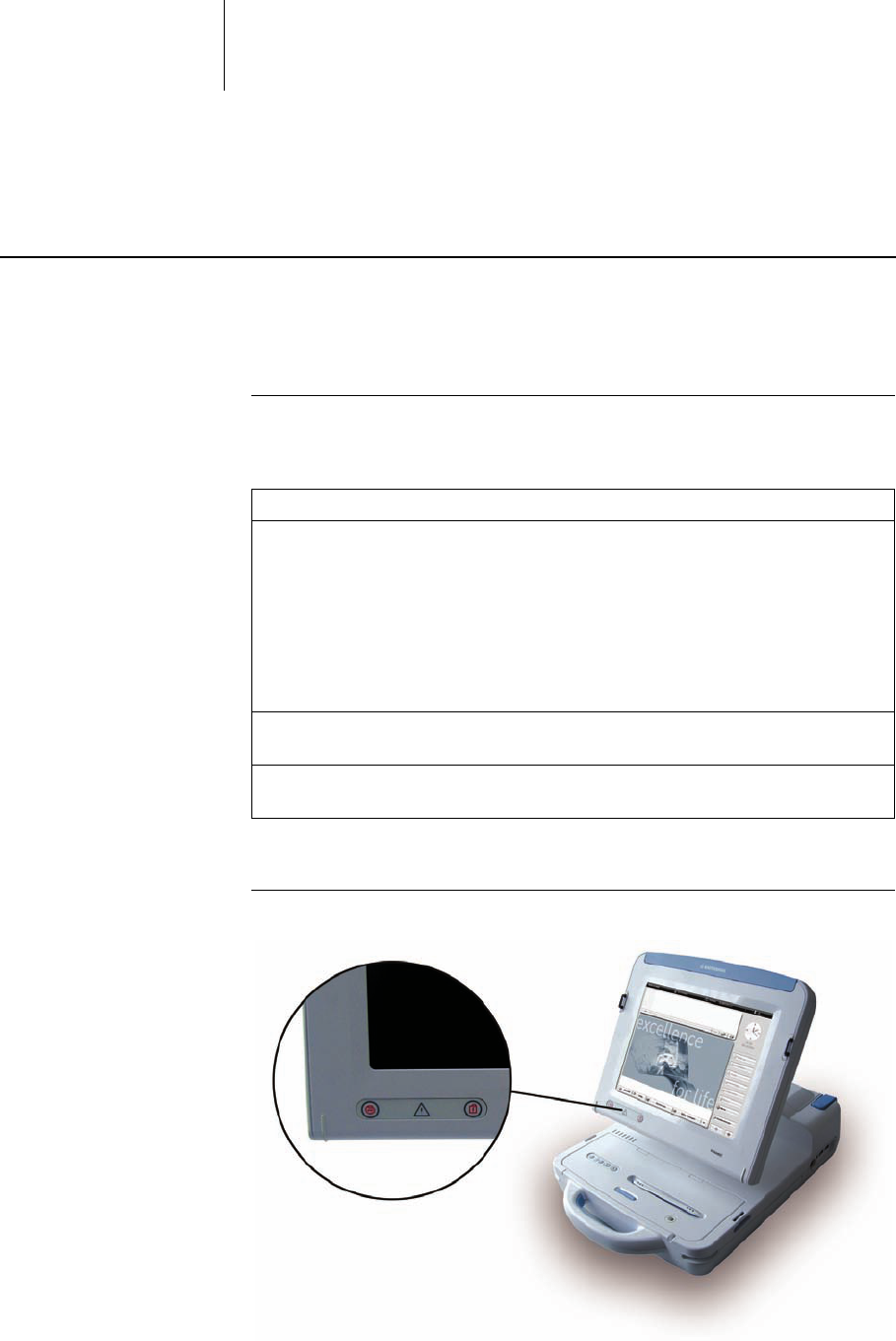
Position of the keys The emergency keys are located on the front of the screen on the lower left.
Bild 1: Location of the emergency keys
Designation Description
1 Emergency keys • Safe program key to switch on the safe program
of the implanted device (emergency pacing).
The safe program comes into effect immedi-
ately (see: Emergency Programs, p. 33)
• Emergency shock key to trigger emergency
shock via the ICD. The emergency shock is
delivered in 2 controlled steps (see: Emergency
Programs, p. 33)
2 Printer keys Keys for controlling the internal printer (see: Using
the Internal Printer, p. 39)
3 On/off key Key for switching the device on and off (see:
Switching On and Off, p. 29)
32 Using Renamic
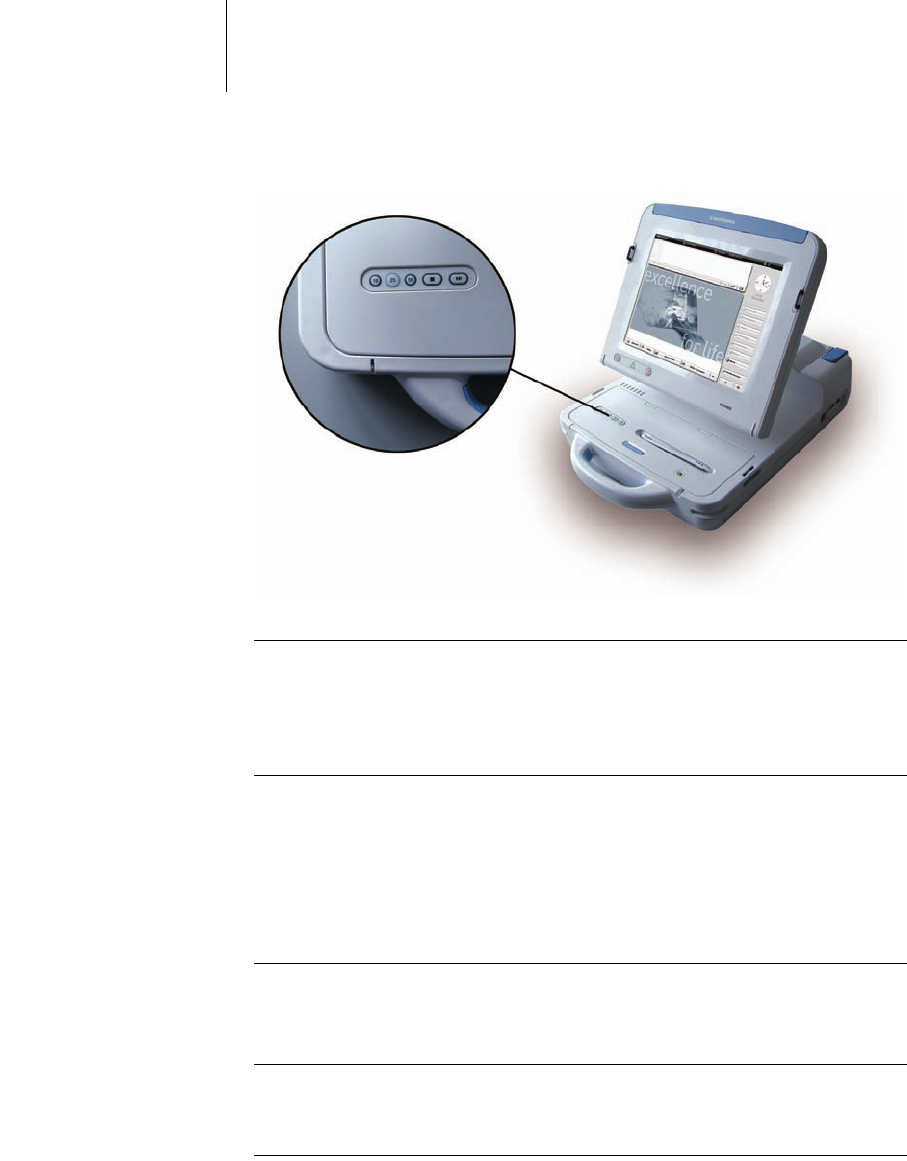
The printer keys are located on the left side of the PGH compartment lid.
Bild 2: Location of the printer keys
On/off light indicator The on/off light indicator shows whether the device is switched on (lit) or off (not
lit).
It is located on the front left edge of the device. Refer to figure PGH compartment,
p. 19, item #25.
Screen The device screen is a touch screen that is operated using a stylus or finger.
The following is displayed on the screen:
• Parameters and measured values
• ECG, IEGM and marker channel
• Buttons
Buttons on the screen The individual functions can be selected using the software interface buttons on the
screen. These buttons respond to touch or light pressure from the stylus or finger
similarly to keys.
Signal beep The device issues a sound when you press a key or button.
You can use the software program to switch off key and button sounds.
33 Using Renamic
Emergency Programs
QUICK REFERENCE GUIDE
FOR EMERGENCIES
SAFE PROGRAM (EMERGENCY PACING):
DELIVER EMERGENCY SHOCK:
Purpose of the emergency
buttons
The emergency buttons are used for the following:
• They implement the parameters of the safe program (emergency pacing) by
pressing a single button.
• They start emergency pacing or emergency shock.
Condition The programming head creates telemetry contact between Renamic and the active
implanted device.
Sequence When the emergency buttons are activated, the following will occur:
• The current active programming in the implanted device will be deactivated.
• The corresponding emergency parameter values will be activated and the
selected emergency program will start.
Step Action
1 Position the PGH above the implanted device so that telemetry contact
is created.
2 Press the safe program button:
Step Action
1 Position the PGH above the ICD so that telemetry contact is created.
2 Press the emergency shock button:
3 In the dialog window, select [EMERGENCY SHOCK].
WARNING
Danger to the patient from high electrical energies
High levels of electrical energy are conducted to the patient through the emer-
gency programs.
• Only activate the safe program or emergency shock under the supervision of
a physician.
34 Using Renamic
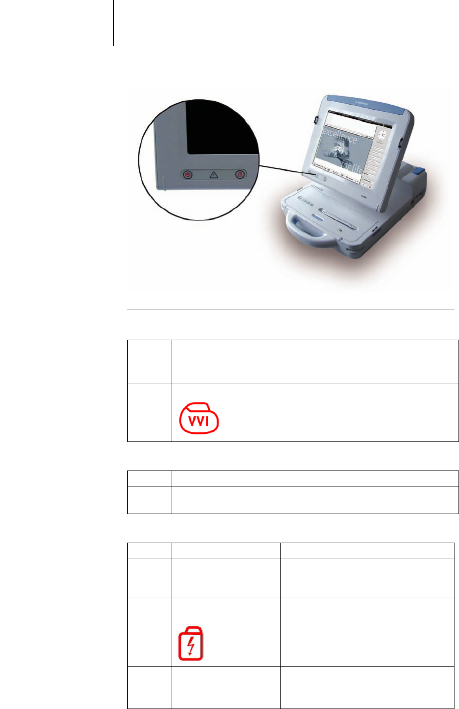
Location of the emergency
buttons
Bild 3: Location of the emergency buttons on the device
Start emergency pacing Proceed as follows:
Stop emergency pacing Proceed as follows:
Trigger emergency shock Proceed as follows:
Step Action
1 Position the PGH above the implanted device so that telemetry contact
is created.
2 Press the safe program button:
Step Action
1 Activate the desired permanent parameters in the program of the
implanted device and transfer them to the implanted device.
Step Action Result
1 Position the PGH above
the ICD so that telemetry
contact is created.
Telemetry contact is created between the
ICD and the Renamic programmer.
2 Press the emergency
shock button:
• The emergency shock parameters are
activated.
• As a safety precaution, a dialog
window will give you the option to
cancel this action.
3 In the dialog window,
select [EMERGENCY
SHOCK].
• The ICD shock capacitors are charged.
• Renamic triggers a 30 or 36 J emer-
gency shock via the ICD.

35 Using Renamic
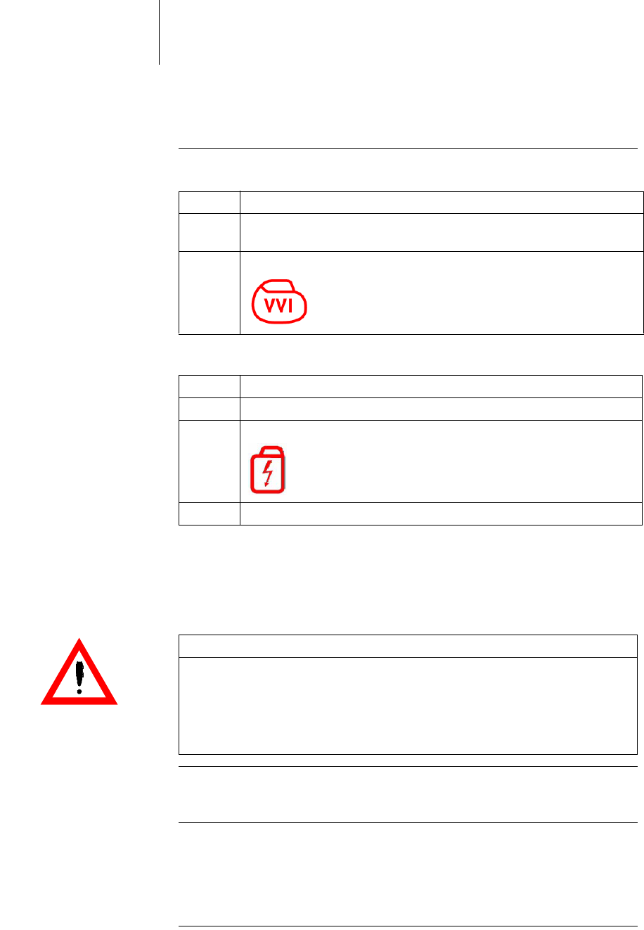
Parameter values Tabelle 1: Safe program default parameter values
Tabelle 2: Emergency shock default parameter values
Parameter Value
Mode VVI
Basic rate 70 ppm
Pulse amplitude 7.5 V
Pulse width 1.5 ms
Parameter Value
Shock waveform Biphasic
Type DF (defibrillation shock)
Energy • 30 J
• Implanted device with high engergy: 36
J
36 Using Renamic
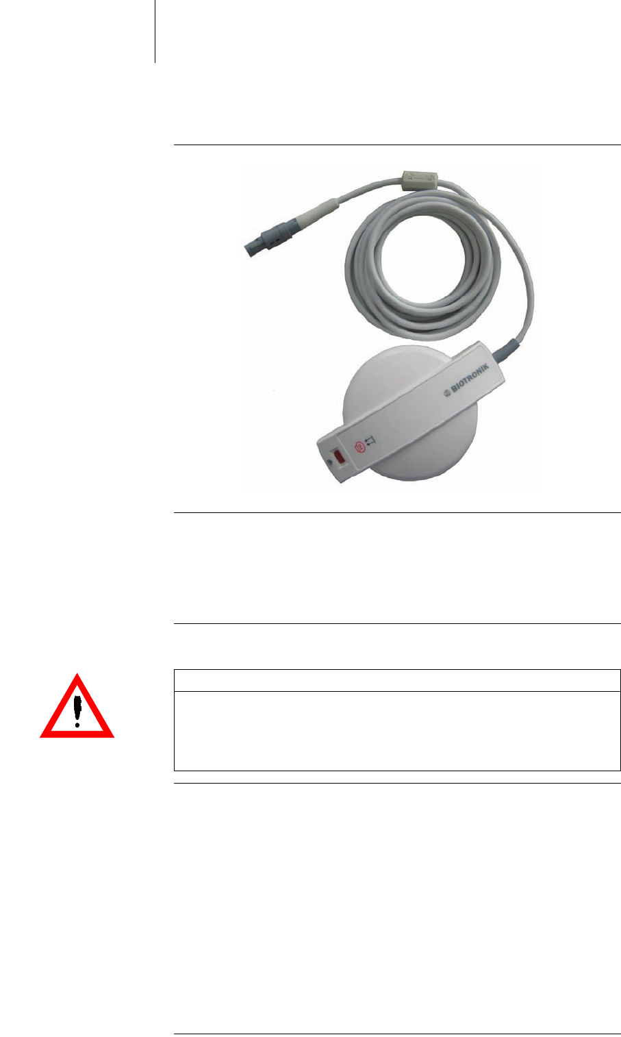
Programming Head
Bild 4: Programming head (PGH) with connection cable
Prerequisites • Connect the programming head to the Renamic programmer before you turn on
the device (see: Connect programming head, p. 23).
• If you are using the programming head under sterile conditions, cover the
programming head with a sterile cover (see: Scope of Delivery and Accessories,
p. 49).
Telemetry: Principle Communication between the programmer and the implanted device takes place
through telemetry via the programming head (PGH). The output data from the
implanted device (digital and analog) are converted into digitally coded pulses and
transmitted over an inductive coupling between the coils of the programming head
and those of the implanted device.
With some implanted devices, telemetry cannot be carried out until a reed switch in
the implanted device has been closed. For this purpose, a strong permanent
magnet has been integrated into the programming head. Before the programming
head and the implanted device can exchange data, the reed switch in the implanted
device is closed.
When the reed switch is open, telemetry is blocked. This protects the implanted
device from unintentional reprogramming. With some implanted devices, closing
the reed switch also switches the device over to an asynchronous pacing program
(see the technical manual of the respective implanted device).
CAUTION
Risk to magnetically sensitive objects
The programming head contains a strong magnet.
• Do not place the programming head close to magnetically sensitive objects
such as magnetic data media, credit cards or wristwatches.
37 Using Renamic
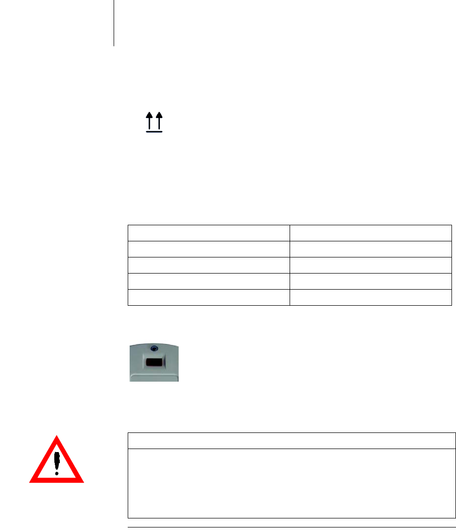
Establishing telemetry Each programming head features arrows to assist in positioning the head. Silicone
tines on the underside prevent the head from slipping.
Bild 5: Position indicator for the programming head
• Place the programming head on the patient above the active implanted device
so that the arrows are pointing toward the patient's head.
Tabelle 3: Status display for telemetry contact
The LED at the front of the programming head indicates the telemetry contact to
the implanted device:
Using the safe program The programming head is equipped with its own safe program button.
Bild 6: Key for the safe program on the programming head
This function can be started immediately from any application if the programming
head is positioned above the implanted device.
LED status (flashing) Telemetry status
Green Telemetry contact optimal
Orange Telemetry contact in limit range
Red Telemetry contact disturbed
Off No telemetry contact
WARNING
Danger to the patient from high electrical energies
High levels of electrical energy are conducted to the patient by the emergency
program.
• Only activate the safe program or emergency shock under the supervision of
a physician.

38 Using Renamic
Communication with Active Implanted Devices
Software The interaction/communication between the Renamic programmer and active
implanted devices is controlled using software specific to each implanted device.
• The software is installed on the Renamic device drive by BIOTRONIK employees.
• Software can only be updated on site by BIOTRONIK employees or by those
authorized by BIOTRONIK.
Interrogating and program-
ming the implanted device
BIOTRONIK implanted devices can communicate with Renamic in both directions
via the programming head. As soon as the programming head is correctly posi-
tioned over the implanted device, the program data and all data stored in the
implanted device can be transmitted to the Renamic programmer.
Depending on the implanted device, a large number of adjustable parameter sets
are available. These parameter sets are combined and saved in the program that is
currently active. The Renamic programmer can detect obvious programming
errors and requires that these errors be corrected before the program is trans-
ferred to the implanted device.
The following programs can be transmitted:
• Permanent program
• Temporary program
•Safe program
A temporary program is a program that the pacemaker uses to provide temporary
pacing as long as the programming head is in position.
A permanent program is a program that is programmed in the pacemaker using
the programming head and which performs pacing permanently without telemetry
contact to the programming head.
A safe program is a device-specific program used for safety pacing with high energy
in either VVI or SSI mode.
Data transfer The follow-up data can be saved, sorted and/or exported as follows:
• Connect an external PC system for data processing (e.g., CDM 3000)
• Connect an external printer for printing out all data, with the exception of real-
time ECGs
• Connect a USB flash drive
Reports Internal printer for printing out the complete documentation:
• All follow-up reports such as program and test data as well as saved data
• All real-time ECGs, ECGs, IEGMs, event markers
Note: Use of a temporary program can be stopped at any time and the permanent
program of the implanted device can be automatically reactivated with the
following:
• Removing the programming head
Or:
• Switching off the programmer.
39 Using Renamic
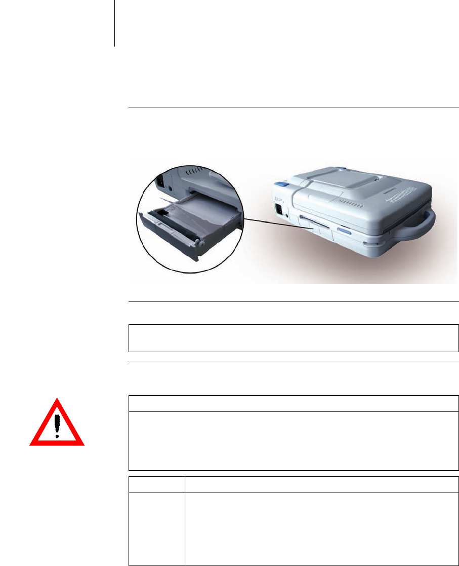
Using the Internal Printer
The Renamic programmer has a high definition thermal printer that is capable of
printing graphics. The device prints on thermal folding paper. See: Scope of
Delivery, p. 49
Bild 7: Paper tray: position on the device
Inserting paper Proceed as follows:
Note: The thermal paper printouts are moisture-sensitive and fade when
exposed to strong sunlight. Make copies for permanent documentation.
CAUTION
Printouts that cannot be used or cause damage to the printer
The use of paper not intended for this device can lower the quality of the printout
or cause damage to the device.
• Use paper specified by BIOTRONIK at all times. See: Scope of Delivery, p. 49.
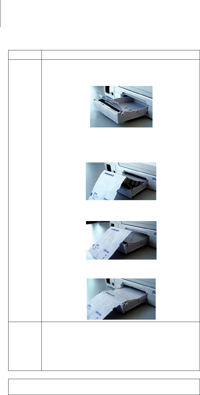
Step Action
1 To open the paper tray:
• Open the lid by lightly pushing it up.
• Pull the tray out until it stops.
• In order to remove the tray from the device, press the lever
down on the right side.
40 Using Renamic
2 To insert paper:
• Press back the separating flap.
• Pull back the first page of the paper block.
• Place the block of paper in the tray from above so that the wide
marking of the paper block is on the left side.
• Place the separating flap under the first sheet of paper.
• Pull the first page over the separating flap and rubber roller.
3 To close the paper tray:
• Push the tray back into the device until it stops.
If there is too much paper in the tray and it is difficult to push it
back into the device, then tear off enough paper and repeat the
steps.
• The cover locks automatically.
Note: The printer is ready for operation only when the paper tray has been
inserted and closed.
Step Action
41 Using Renamic
Print The printer buttons are located on the left front side.
Bild 8: Printer buttons
Key assignment from left to right:
• You can use the numbered keys to switch on the printer with the respective
printing speed in mm/s.
• Use the stop key to quit printing.
• The feed button is used to move the paper to the beginning of the next page. The
feed mechanism automatically advances the paper to the next tear-off edge.

42 Using Renamic
Using an External Printer
Prerequisites You can connect an external printer to Renamic under the following electrical
safety conditions:
• With the exception of the wireless connection, after the system has been
installed in the hospital, compliance with the leakage current limit values
according to IEC 60601-1, paragraph 16.6 must be demonstrated.
• The printer must be set up outside the patient environment (at least 1.5 meters
away from the patient). You can use any printer that supports the PCL5 printer
language and is compatible with a generic HP driver.
Configurations In order to ensure electrical safety, it is only permissible to connect an external
printer if one of the following conditions is met for the connection between the
printer and Renamic:
• The printer is Bluetooth-compatible. The connection to Renamic is established
using the accessory Bluetooth adapter (See Equipping the device with a Blue-
tooth adapter, p. 27).
• The printer is powered via the mains supply and is connected to the USB port of
Renamic via an isolating separator (IEC 60601-1, Paragraph 16.5) with a dielec-
tric strength of at least 1.5 kV (e.g. an isolating USB hub model UISOHUB4 by
B&B electronics).
• The printer is supplied directly from the mains by a medical device power
supply. Connect it to the USB port of Renamic.

43 Using Renamic
ECG and IEGM Functions
Connecting the ECG cable See section: Connect ECG cable, p. 23
ECG recorder and ECG
monitor
All ECGs can be displayed in real time in the recorder or trigger mode and printed
on the internal printer.
ECG leads Tabelle 4: Accessories for ECG leads
See also: Accessories, p. 49
Recording ECGs and IEGMs The intracardiac electrograms received from the implanted device and the surface
ECG can be displayed and printed simultaneously. The recording of the surface ECG
is independent of other functions, so that the implanted device can be interrogated
and programmed during the ongoing ECG display. The recorded electrograms can
be saved and measured using electronic calipers.
Overmodulated ECG input When the ECG input is overmodulated, the signal is displayed only as a solid line on
the upper frame of the ECG window. Proceed as follows to fix overmodulation:
Lead Patient Device
Up to 3 leads (Einthoven) Permitted adhesive and clamp
leads
PK-222
Note: Follow the instructions for connecting the ECG cable PK-222 in section
Connect ECG cable, p. 23.
Note: It is not permitted to use the device's ECG display for diagnostic purposes
because it does not meet all requirements for diagnostic ECG devices (IEC 60601-
2-25).
Step Description
1 Test the lead contacts.
2 Remove other devices from the patient.
3 Turn off the sources of interference.

44 Using Renamic

45
5 Appendix
Appendix5xxxxxx--XDoc-classRenamic
Technical Data
Physical characteristics
General classification
Longevity
Ambient conditions
Touch screen
Category Design
Dimensions (W x D x H) 345 x 476 x 125 mm
Weight with cables and programming
head
10,5 kg 10%
Housing material PC/ABS
Category Design
Classification AIMD according to directive 90/385/
EEC
Safety class I
Protection rating IP 30
Operating mode Continuous operation
Category Design
Longevity 6 years
Category Design
Temperature range for operation +10°C ... +40°C
Temperature range for storage 0°C ... +50°C
Relative humidity 30% ... 75%, no condensation
Atmospheric pressure 700 ... 1060 hPa
Operation at altitudes Up to 3000 m
Category Design
Size 12.1'
Tilt 35 – 80 °
Resolution 800 x 600 SVGA
Contrast Ratio (CR) 200:1
Brightness At least 150 cd/m

46 Appendix
ECG module
Programming head
Power cord port
Mass storage
Category Design
Applied part classification BF, defribrillation-proof with PK-222
Leads 3 (Einthoven)
A/D converter 12 bits
Scan rate 500 ... 1000 Hz
Interface Redel plug, 14-pole
Category Design
Applied part classification BF
Dimensions (W x D x H) 145 x 42 x 97 mm
Weight 0.3 kg
PGH cable 2.9 m
Protection rating IP 30
Magnetic flux density Max. 3 mT
Interface Redel plug, 14-pole
Category Design
Supply voltage 100 – 115 V, 10% / 60 Hz / 1.2 A
/ AC
220 – 230 V, 10% / 50 Hz / 0.6 A
/ AC
Safety class I
Fuse type 3.15 A; T; 250 V (G fuse IEC
60127 5 x 20 mm)
Max. power input Duration 100 W
Peak 150 W
Efficiency 75%
(at 230 V/50 Hz)
On/off LED Green LED, lit continuously
Category Design
Type Hard disk
Shock resistance Min. 175 G (operating)
Min. 700 G (non-operating)
Storage capacity Min. 40 GB
Magnetic field resistance 50 mT

47 Appendix
Internal printer
MICS
GSM module
UMTS module
Category Design
Type Thermal printer
Printing width 4'
Resolution 8 Dots/mm
Paper Z-fold
Paper format (B x L) 112 x 125 mm
Paper supply 200 + 10 sheets
Category Design
Rate band 9 channels 402 – 405 Mhz
Range 300 kHz
Standard channel 403.65 MHz
Modulation FSK
Encoding Manchester
Data rate 32768, 16384, 8192, 4096, 2048 bit/s
(unencoded)
Category Design
Model GSM/GPRS quadband Motorola
Type G24L bzw. G24
GSM rate 850 MHz, 900 MHz,
1800 MHz, 1900 MHz
Transmission power 2 W: 850/900 MHz
1 W: 1800/1900 MHz
GPRS Multislot class 10
(4 Down, 2 Up)
Category Design
Model Motorola, 4 band GSM +
3 band UMTS
Type H24
UMTS rate 850 MHz, 1900 MHz, 2100 MHz
GSM rate 850 MHz, 900 MHz,
1800 MHz, 1900 MHz
UMTS transmission power 0,25 W
GSM transmission power 2 W: 850/900 MHz
1 W: 1800/1900 MHz
UMTS Max. Range:
Uplink: 5.76 Mbps
Downlink: 7.2 Mbps
UE CAT [1-8], 11, 12 supported
Compressed mode (3GPP TS25.212)
GSM Multi-slot class 12
(4 down, 4 up, 4 total)
Coding scheme: CS1–CS4

48 Appendix
WLAN module
Category Design
Transmitter rate Europe: 2,412 GHz bis 2,472 GHz
USA: 2,412 GHz bis 2,462 GHz
Max. transmission power 100 mW
Protocols WEP, WPA, WPA2, HTTPS
Standards IEEE 802.11b
IEEE 802.11g
Channels Europe: 13 channels
USA: 11 channels

49 Appendix
Scope of Delivery and Accessories
Scope of Delivery Renamic (Order no.: 371960)
Accessories
Item designation Amount Order no.
Renamic (single device) WLAN module* Customer-specific 379173
GSM module* Customer-specific 379174
UMTS module* Customer-specific 379366
Without module Customer-specific 365533
Programming head 1 371588
Power cord 1 Country-specific
PK-222-EU / 2.8 m or PK-222-US / 2.8 m 1 Country-specific
Bluetooth USB adapter 1 367929
Stylus 1 371586
Thermal printer paper 2 348728
PK Electrode Clip 1 340293
Multilingual technical manual (de, en, es, fr, it) 1 377213
Technical manual ZH (printed) Country-specific 370975
Quick reference guide DE (printed) Country-specific 370976
Quick reference guide EN (printed) Country-specific 370977
Quick reference guide ES (printed) Country-specific 370978
Quick reference guide FR (printed) Country-specific 370979
Quick reference guide IT (printed) Country-specific 370980
Quick reference guide ZH (printed) Country-specific 370981
*Not available in all countries
Item designation Description Order no.
PK-222-EU / 2.8 m ECG cable with banana plug for extremity leads according
to Einthoven
335284
PK-222-US / 2.8 m Same as the PK-222-EU with country-specific color coding
of the banana plugs
335281
PGH ICD Programming head without magnet with straight cable (2.9
m)
371589
NK-3 Power cord EU 107526
NK-11 (3 m) Power cord US 128865
NK-16-GB (2 m) Power cord for the United Kingdom 330705
NK-19-CN (2.5 m) Power cord for Canada 339034
NK-21-AU,UY (2.5 m) Power cord for Australia and Uruguay 339035
NK-22-AR (2.5 m) Power cord for Argentina 339039
NK-26-CL, IT (2.5 m) Power cord for Chile and Italy 339043
NK-28-DK (2.5 m) Power cord for Denmark 339059
NK-25-CH (2.5 m) Power cord for Switzerland 339042

50 Appendix
Optional accessories
(compatibility with third
party suppliers)
NK-27-IL (2.5 m) Power cord for Israel 339044
NK-33-BR (2.5 m) Power cord for Brazil 378933
Memory stick (compatible with
Renamic)
USB flash memory stick for connection to the USB inter-
face of the programmer; e.g. for data export
350017
USB adapter for serial interface Virtual serial interface via USB 376437
USB adapter for VGA port Virtual VGA interface via USB 377292
Sterile cover 1 Sterile cover for single use on programming head (cannot
be re-sterilized)
118022
M 50 Permanent magnet; magnetic flux density: 12.5 min. in
mT; dimensions (W x H x D): 60 x 17 x 26; weight: 0.185 kg
(0.408 lb)
112149
Shoulder strap Carrying strap that can be fixed to the Renamic hangers. 371962
Protective cover Protective cover for Renamic 376999
Item designation Description Order no.
Item designation Manufacturer Description
H34 SG Kendall ARBO Adhesive electrodes
T 60 SKINTACT Adhesive electrodes
Type 454 Dahlhausen Adhesive electrodes
Type 460 Dahlhausen Adhesive electrodes
G502 GOLMED Clamp lead
Cruzer Micro SanDisk USB flash memory stick
USB 2.0 to DVI - VGA - HDMI adapter
(61644)
DeLOCK Visual VGA interface via USB
USB 2.0 to Serial (61425) DeLOCK Virtual serial interface via USB
G84-4400LUBDE-0 Cherry Keyboard via USB
Mouse Dell Maus via USB
Passport II; 2.5'; 5400 RPM, 320 GB
(WDXMS3200TE)
Western Digital External hard drive via USB
51 Appendix
Electromagnetic Compatibility in Compliance with EN 60601-1-2:2007
• As the user, you must ensure that the device is operated in a suitable electro-
magnetic environment.
• The following guidelines may not be applicable in all cases. The propagation of
electromagnetic values is, for example, affected by the absorption and reflec-
tion of structures, objects and people. This data is for your personal informa-
tion.
Electromagnetic Emissions
(Table 1)
Recommended safety
distances (Table 6)
• Safety distances help prevent interference if you maintain a minimum distance
between transmitters such as mobile RF telecommunication devices and the
Renamic programmer. The necessary distance depends on the respective
power output of the transmitter.
• For transmitters whose maximum output power is not indicated in the table, the
recommended safety distance [d] can be calculated in meters using an equation
that is suitable for the respective transmission frequency range. P is the
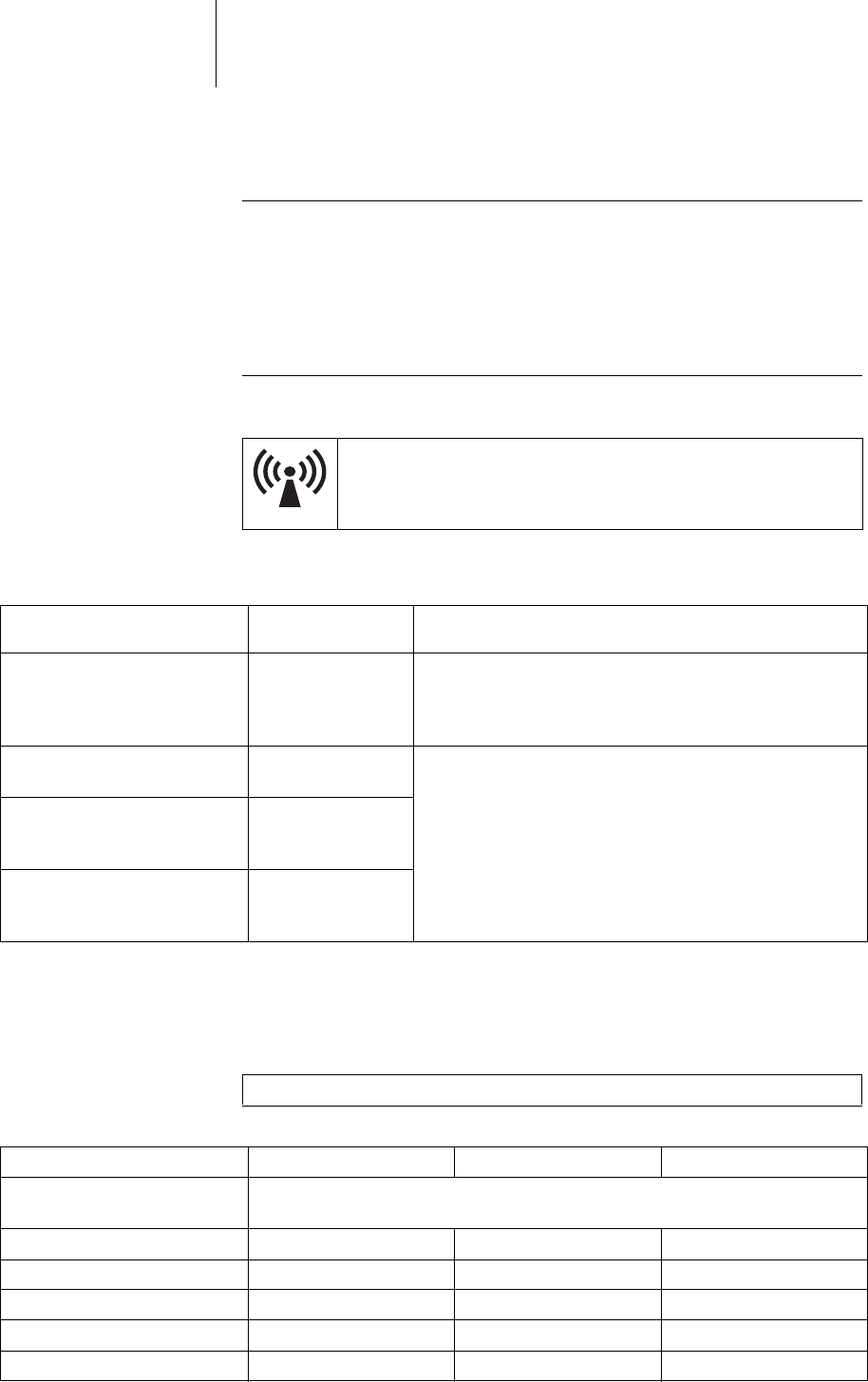
Devices with the warning sign “Beware of non-ionizing radiation”
must not be operated in the environment of the device due to poten-
tial interferences.
Measuring the emitted inter-
ference Compliance Guidelines for the electromagnetic environment
RF interference according to
CISPR 11
Group 1 The device uses RF energy exclusively for its own function.
Therefore, the RF interference emitted is very low and not
likely to cause any interference in nearby electronic equip-
ment.
RF interference according to
CISPR 11
Class B The device is suitable for use in all establishments. This
includes residences and facilities directly connected to the
public power supply network that supplies buildings used
for domestic purposes.
Interference of harmonic oscil-
lations according to IEC 61000-
3-2
Class A
Emitted interference of voltage
fluctuations according to
IEC 61000-3-3
Complies
Note: At 80 MHz and at 800 MHz, the higher frequency range applies.
Transmission frequency 150 kHz to 80 MHz 80 MHz to 800 MHz 800 MHz to 2.5 GHz
Maximum output power of the
transmitter [W]
Safety distance [m]
0.01 0.12 0.12 0.24
0.1 0.37 0.37 0.74
1 1.17 1.17 2.34
10 3.70 3.70 7.40
100 11.7 11.7 23.4

52 Appendix
maximum output power of the transmitter in watts [W] according to the specifi-
cation of the transmitter's manufacturer.
Resistance to electromag-
netic interference
(tables 2 and 4)
• When the measured field strength exceeds the specified compliance level at the
operating location of the Renamic device, observe the device in order to deter-
mine whether it is functioning properly.
• If abnormal performance is observed, change the orientation or the location of
the device. In the frequency range of 150 kHz to 80 MHz, ensure that field
strengths are lower than 3 V/m.
Transmission frequency 150 kHz to 80 MHz 80 MHz to 800 MHz 800 MHz to 2.5 GHz
Equation d = 1.17 P d = 1.17 P d = 2.34 P
Note: UT is the mains alternating voltage before applying the test levels.
Test of resistance to interfer-
ence Test level according to
IEC 60601-1-2 Compliance Guidelines for the electromagnetic
environment
Electrostatic discharge (ESD)
according to IEC 61000-4-2
6 kV contact
discharge
8 kV air discharge
Same as test
level
• Operate the devices on floors made
of wood, concrete, or ceramic tile.
If the floor is covered with synthetic
material, the relative humidity
must be at least 30%.
Fast transient electric interfer-
ences (bursts) according to
IEC 61000-4-4
2 kV for power supply
lines
1 kV for input and
output lines
Same as test
level
• Ensure that the power supply
quality is that of a typical commer-
cial and/or hospital environment.
Surges according to
IEC 61000-4-5
1kV push-pull voltage
2 kV for common-
mode voltage
Voltage drops, brief interrup-
tions and fluctuations in the
supply voltage according to
IEC 61000-4-1
5% UT for 1/2 cycle
95% drop
40% UT for 5 cycles
60% drop
70% UT for 25 cycles
30% drop
5% UT for 5 s 95%
drop
Same as test
level
• Ensure that the power supply
quality is that of a typical commer-
cial and/or hospital environment.
• If you require continued operation
during power supply interruptions,
connect the device to an uninter-
ruptible power supply or use a
battery for operation.
Magnetic field at the supply
frequencies (50/60 Hz)
according to IEC 61000-4-8
3A/m Same as test
level
• Ensure that the magnetic field
strengths are at levels character-
istic of a location in a typical
commercial and/or hospital envi-
ronment.
Note: At 80 MHz and at 800 MHz, the higher frequency range applies.

53 Appendix
Test of resistance to interfer-
ence Test level according to
IEC 60601-1-2 Compliance Guidelines for the electromagnetic
environment
Conducted RF interferences
according to IEC 61000-4-6
3V
eff 3 V • Maintain safety distance of mobile
radio equipment to the Renamic
programmer; see table 6.
• The field strength of stationary
transmitting devices must be
measured on site and must be
lower than the compliance level at
all frequencies: consider
conducting a study of the site.
• The field strength must be lower
than 3 V/m over the frequency
range of 150 kHz to 80 MHz.
Radiated RF interferences
according to IEC 61000-4-3
3 V/m 80 MHz to
2.5 GHz
3V/m

54 Appendix
Country-Related Information
UL certification Renamic (Order no.: 371960) has been certified by Underwriters Laboratories Inc.
in accordance with UL 2601-1 and CAN/CSAC22.2 No. 601.1-M90.
UL-certified devices are identified as follows:
Distribution in the US and
Canada
In the US and Canada, the device must be connected to a center-tapped power
outlet if the voltage network carries 230 V at 60 Hz.
Identifications Industry Canada:
• Renamic: 4708A-RENAMIC
• Programming head: 4708A-ICSPGH
The code IC in front of the approval/registration number indicates that the tech-
nical requirements for Industry Canada are met.
Federal Communication Commission of the USA:
• Renamic: QRIRENAMIC
• Programming head: QRIICSPGH
Modifications which are not expressly approved by this company may void the rights
to operate the devices.
FCC RF exposure
requirements
Your device is equipped with a radio frequency (RF) transceiver for wireless
communications. These communication are transmitted via an RF assigned by the
Federal Communications Commission's (FCC) for Medical Implant Communica-
tions Service (MICS).
This device may not interfere with stations operating in the 400.150–406.000 MHz
band in the Meteorological Aids, Meteorological Satellite, and Earth Exploration
Satellite Services and must accept any interference received, including interfer-
ence that may cause undesired operation.
This device complies with Part 15 of the FCC Rules. Operation is subject to the
following two conditions: (1) this device may not cause harmful interference, and (2)
this device must accept any interference received, including interference that may
cause undesired operation.
55 Appendix
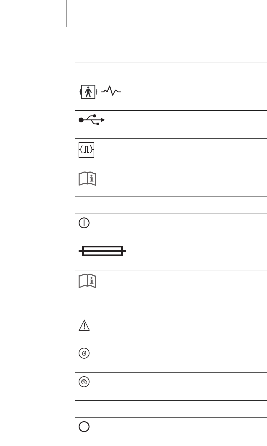
Symbols on the Components
Symbols on the right side of
the device
The symbols mean the following:
Symbols on the left side of
the device
The symbols mean the following:
Symbols on the monitor The symbols mean the following:
Symbols on the PGH
compartment
The symbols mean the following:
ECG port with applied part classification BF, defibril-
lation-proof
USB ports
Binary interface (slot for expansion module)
Follow the instructions in the technical manual!
On/off button
Fuse
Follow the instructions in the technical manual!
Caution!
Emergency shock button
Safe program button
Key for setting printer speed to 10 mm/s
10
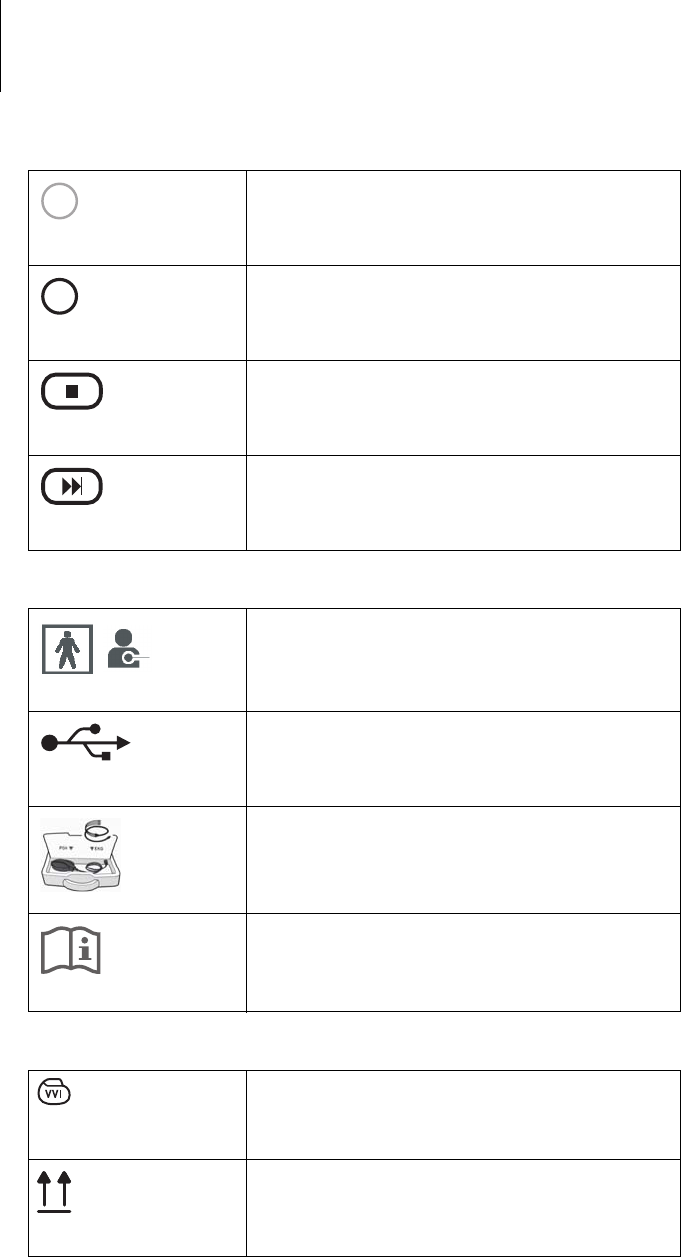
56 Appendix
Symbols in the PGH
compartment
The symbols mean the following:
Symbols on the program-
ming head
The symbols mean the following:
Key for setting printer speed to 25 mm/s
Key for setting printer speed to 50 mm/s
Key used to stop printing
Feed button to feed the paper to the beginning of the
next page
25
50
Programming head connection with applied part
classification BF
USB port
Position and connection of the programming head
and position of the ECG cable
Follow the instructions in the technical manual!
Symbol for the safe program key
Position indicator for the programming head
57 Appendix
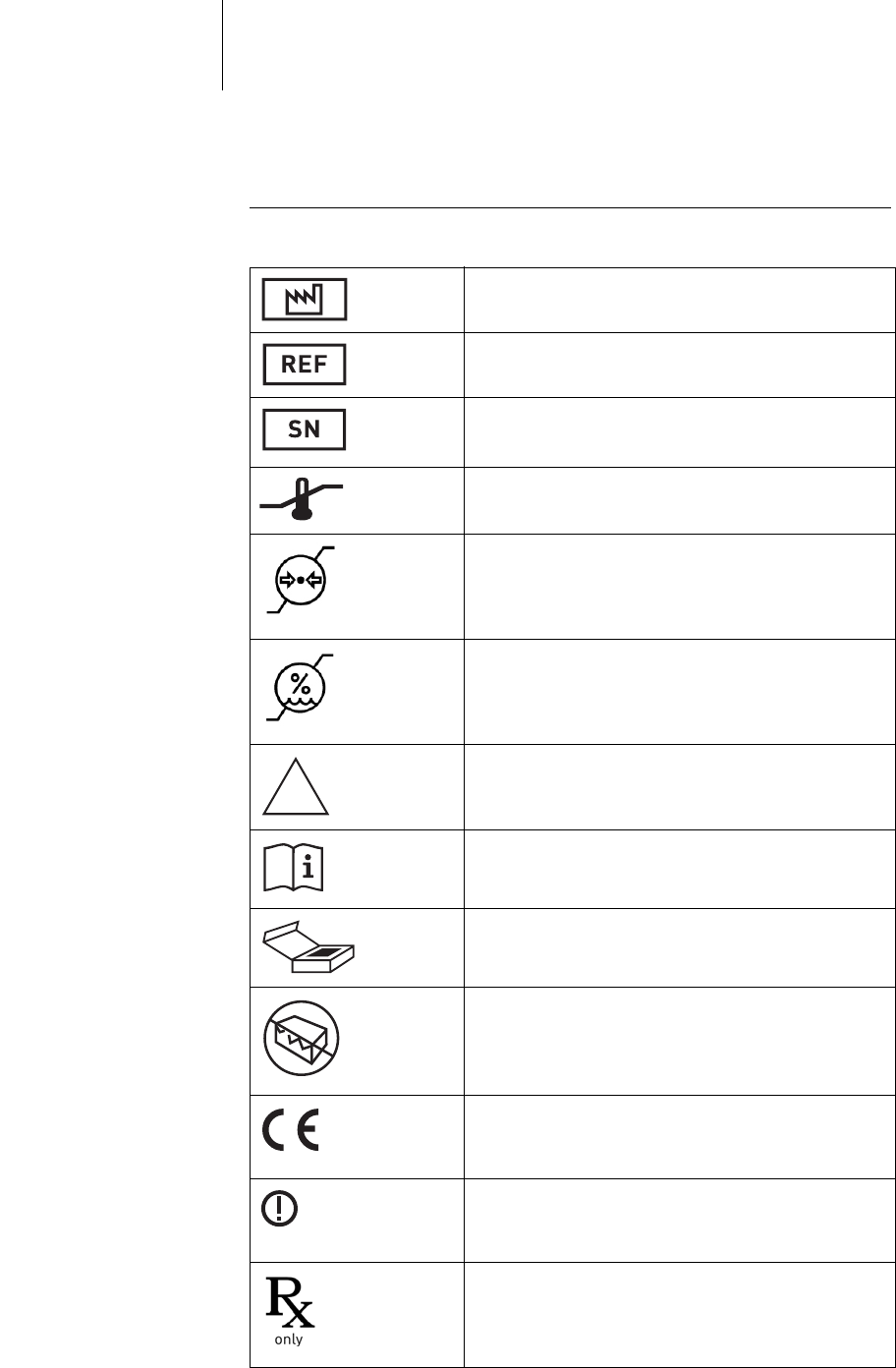
Legend for the Label
The label icons symbolize the following:
Manufacturing date
BIOTRONIK order number
Serial number
Acceptable temperature ranges for storage
Acceptable atmospheric pressure range for storage
Acceptable relative humidity range for storage
Non-sterile
Follow the instructions in the technical manual!
Contents
Do not use if package is damaged!
European approval mark
Country-specific restrictions concerning the circula-
tion and implementation of the device
Caution: Federal (U.S.A.) law restricts this device to
sale by, or on the order of, a physician
NON
STERILE
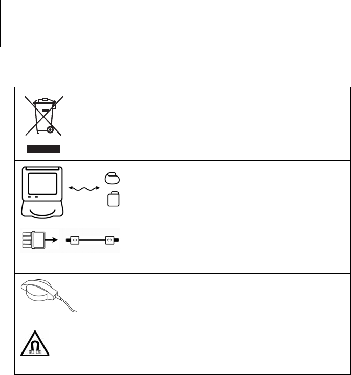
58 Appendix
Device contains materials that must be correctly
disposed of in accordance with environmental
protection regulations.
European Directive 2002/96/EC regarding waste
electrical and electronic equipment (WEEE) applies.
Return devices that are no longer used to BIOTRONIK.
Programmer (Renamic) for electrotherapy implanted
devices
Cable and adapter
Programming head
Warning: Magnetic field

59
6 Directories
Directories6xxxxxx--XDoc-classRenamic
List of Keywords
C
Characteristics, 45
Cleaning, 15
Connect external devices
ECG cable, 23
Programming head, 23
Connection of external devices
Bluetooth adapter, 26
USB devices, 25
Connection of external devices, external printer, 42
D
Damage, 12
Defibrillation, 11
Device button
Emergency pacing, 33
Emergency shock, 33
Disinfecting, 15
Disposal, 16
Disposal of cables, 16
E
ECG, 43
Electromagnetic compatibility, 51
Electromagnetic emissions, 51
Electromagnetic interference, 14
Test, 14
Electrostatic potentials, 10
Emergency
Equipment, 10
Emergency pacing, 33
Emergency shock, 33
Parameter values, 35
Expertise, required, 8
I
IEGM, 43
Installation site, 12
Intended use, medical, 7
M
Maintenance, 15
Maintenance, inspection, 15
Maintenance, test before each use, 15

60 Directories
P
Patient environment, 12
Power Supply, 28
Printer
external, 42
internal, 39
Programming head, 36
R
Recommended safety distances, 51
Resistance to electromagnetic interference, 52
Risks, 9
S
Safe program
Key on the programming head, 37
Parameter values, 35
Safety instructions, summary, 10
Scope of delivery and accessories, 49
Software, 38
Sterilization, 15
T
Technical data, 45
Ambient conditions, 45
ECG module, 46
General classification, 45, 47, 48
Internal printer, 47
Longevity, 45
Mass storage, 46
Physical characteristics, 45
Power cord port, 46
Programming head, 46
Touch screen, 45
Technical manual, 6
Telemetry
Principle, 36
Status display for contact, 37
Transport damages, 12
U
Use with other devices, 13