BIOTRONIK SE and KG TACHNXT implantable cardioverter defibrillator User Manual
BIOTRONIK SE & Co. KG implantable cardioverter defibrillator
Contents
- 1. 15a_TACHNXT UserMan_Ilesto
- 2. 15b_TACHNXT UserMan_Iforia
15b_TACHNXT UserMan_Iforia
Iforia
ICD Family • Tachyarrhythmia Therapy • Cardiac Resynchronization Therapy
xxx
xxx
ICD Familie • Tachyarrhythmietherapie • Kardiale Resynchronisationstherapie
xxx
xxx
xxx
xxx
xxx
xxx
xxx
xxx
Technical Manual
Technická příručka
Brugermanual
Gebrauchsanweisung
Manual técnico
Käyttöohje
Manuel technique
Manuale tecnico di istruzione
Gebruikshandleiding
Instrukcja obsługi
Manual técnico
Bruksanvisning
• en
• cs
• da
• de
• es
•
• fr
• it
• nl
• pl
• pt
• sv
( )
393467--B_GA_Iforia-I-ProMRI_mul-01xx_Cover.indd 1 25.10.2012 17:51:48
BIOTRONIK SE & Co. KG
Woermannkehre 1
12359 Berlin · Germany
Tel +49 (0) 30 68905-0
Fax +49 (0) 30 6852804
sales@biotronik.com
www.biotronik.com
12-D-xx
Revision: B (2012-xx-xx)
© BIOTRONIK SE & Co. KG
All rights reserved. Specications subject
to modication, revision and improvement.
® BIOTRONIK Home Monitoring, (ProMRI),
IEGM-Online HD and SMART Detecton are
registered trademarks of BIOTRONIK SE & Co. KG
0123
0681 2012
393467--B_GA_Iforia-I-ProMRI_mul-01xx_Cover.indd 2 25.10.2012 17:51:48
en • English ................................................................................................................................................................. 2
de • Deutsch ................................................................................................................................................................ 24
393467--B
393467--B_GA_Iforia_ProMRI_mul-02.book Page 1 Friday, November 16, 2012 11:18 AM

2
en • English
Product Description
Intended Medical Use
Intended use
Iforia 3/5/7 is part of a family of implantable cardioverter-defibrillators (ICDs). Primary
objective of the therapy is to prevent sudden cardiac death. Furthermore, the device is
capable of treating bradycardia arrhythmias and cardiac resynchronization therapy
with multisite ventricular pacing.
The implantation of an ICD is a symptomatic therapy with the following objectives:
•
Termination of spontaneous ventricular fibrillation (VF) through shock delivery
•
Termination of spontaneous ventricular tachycardia (VT) through antitachycardia
pacing (ATP); in case of ineffective ATP or hemodynamically not tolerated VT, with
shock delivery
•
Cardiac resynchronization through multisite ventricular pacing (triple-chamber
devices)
•
Compensation of bradycardia through ventricular (single-chamber devices) or
AV sequential pacing (DX, dual- and triple-chamber devices)
Diagnosis and therapy forms
The device monitors the heart rhythm and automatically detects and terminates
cardiac arrest resulting from ventricular tachyarrhythmia. All major therapeutic
approaches from the field of cardiology and electrophysiology are included. BIOTRONIK
Home Monitoring
®
enables physicians to perform therapy management at any time.
Required expertise
In addition to having basic medical knowledge, the user must be thoroughly familiar
with the operation and the operation conditions of a device system.
•
Only qualified medical specialists having this special knowledge required are
permitted to use implantable devices.
•
If users do not possess this knowledge, they must be trained accordingly.
Indications
Iforia can treat life-threatening ventricular arrhythmias with antitachycardia pacing
and defibrillation.
Generally approved differential diagnostics methods, indications, and recommenda-
tions for ICD therapy apply to BIOTRONIK devices. See the guidelines of cardiology
associations for guidance.
We recommend observing the indications published by the German Cardiac Society
(Deutsche Gesellschaft für Kardiologie, Herz- und Kreislaufforschung) and the ESC
(European Society of Cardiology). This also applies to the guidelines published by the
Heart Rhythm Society (HRS), the American College of Cardiology (ACC), the American
Heart Association (AHA), and other national cardiology associations.
Single-chamber and dual-chamber
Single-chamber and dual-chamber ICDs are indicated for patients with the following
risk:
•
Sudden cardiac death caused by ventricular arrhythmias
Triple-chamber
Triple-chamber ICDs are indicated for patients with the following risks:
•
Sudden cardiac death caused by ventricular arrhythmias
•
Congestive heart failure with ventricular asynchrony
Iforia is also indicated for primary prophylaxis in congestive heart failure patients.
Contraindications
Known contraindications:
•
Tachyarrhythmia caused by temporary or reversible irritation, e.g. poisoning,
electrolyte imbalance, hypoxia, sepsis or acute myocardial infarction
•
Such frequent VT or VF that the therapies would cause an unacceptably rapid
depletion of the device batteries
•
VT with few or without clinically relevant symptoms
•
VT or VF treatable by surgery
•
Concomitant diseases that would substantially limit a positive prognosis
•
Accelerated idioventricular rhythm
System Overview
Device family
The complete Iforia 3/5/7 device familyconsists of several device types with a
DF-1/IS-1connection.
Single-chamber: VR-T and VR-T DX (only devices with a DF-1/IS-1 connection);
dual-chamber: DR-T; triple-chamber: HF-T. Not all device types are available in
every country.
393467--B_GA_Iforia_ProMRI_mul-02.book Page 2 Friday, November 16, 2012 11:18 AM
en • English
3
Device
The device's housing is made of biocompatible titanium, welded from outside and thus
hermetically sealed. The ellipsoid shape facilitates implantation in the pectoral muscle
area. The connections for bipolar pacing and sensing (and unipolar connections for the
triple-chamber device) as well as for shock delivery are found in the device header. The
housing serves as a potential antipole during shock delivery or in the case of unipolar
lead configuration.
DF-1/IS-1 lead connection
The device labeling provides information pertaining to possible lead connections
depending on the device type and pertaining to connection assignment:
Leads
BIOTRONIK leads are sheathed with biocompatible silicone. They can be flexibly
maneuvered, are stable long-term, and are equipped for active or passive fixation. They
are implanted using a lead introducer set. Some leads are coated with polyurethane
which is known to increase the sliding properties for the lead. Leads with steroids
reduce inflammatory processes. The fractal design of the electrodes provides for low
pacing thresholds. BIOTRONIK provides adapters to connect already implanted leads to
new devices.
Telemetry
Telemetric communication between the device and the programmer can be carried out
following initialization either by applying the programming head (PGH) to the device or
by using radio frequency (RF) telemetry in the programmer. BIOTRONIK calls this func-
tion SafeSync
®
.
Programmer
Implantation and follow-up are performed with BIOTRONIK's portable programmer.
There is one with integrated RF telemetry and one with a separate SafeSync Module.
The programmer is used during implantation to transfer the current device program to
the device. The pacing thresholds can be determined and all tests can be performed
during in-office follow-up. In addition to this, the programmer is used to set mode and
parameter combinations, as well as for interrogation and saving of data from the device.
Leadless ECG, IEGM, markers and functions are displayed simultaneously on the color
display.
Modes
The mode setting depends on the individual diagnosis:
NBD and NBG codes
VVE is the NBD code for the antitachycardia mode of the single-chamber, dual-
chamber, and triple-chamber devices:
DDDR is the NBG code for the antibradycardia mode of the dual-chamber device:
VR DX DR HF
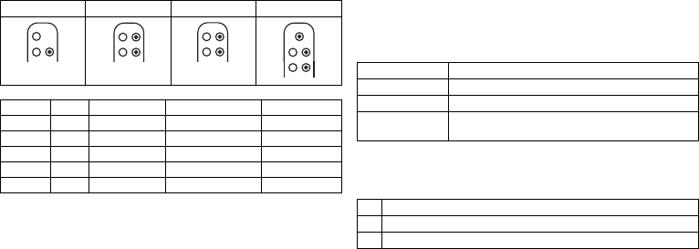
Connector
port Lead
connector Configuration Implantation site Device type
RV DF-1 Shock coil Right ventricle VR, DX, DR, HF
SVC DF-1 Shock coil Superior vena cava VR, DX, DR, HF
RA IS-1 Bipolar Atrium DX, DR, HF
(R)V IS-1 Bipolar (Right) ventricle VR, DX, DR, HF
LV IS-1 Unipolar, Bipolar Left ventricle HF
DF-1
RV
DF-1
SVC
IS-1
RV
DF-1
RV
DF-1
SVC IS-1
RA
IS-1
RV
DF-1
RV
DF-1
SVC IS-1
RA
IS-1
RV
DF-1
RV
DF-1
SVC IS-1
RA
IS-1
RV
IS-1
LV
Device type Modes
VR VVI; VVIR; V00; OFF
DX VDD; VDDR; VDI; VDIR; VVI; VVIR; V00; OFF
DR, HF DDD; DDDR; DDI; DDIR; VDD; VDDR; VDI; VDIR
VVI; VVIR; AAI; AAIR; V00; D00; OFF
V Shock in the ventricle
V Antitachycardia pacing (ATP) in the ventricle
E Detection via IEGM analysis
D Pacing in the atrium and ventricle
D Sensing in the atrium and ventricle
D Pulse inhibition and pulse triggering
R Rate adaptation
393467--B_GA_Iforia_ProMRI_mul-02.book Page 3 Friday, November 16, 2012 11:18 AM

4
DDDRV is the NBG code for the antibradycardia mode of the triple-chamber device:
VDDR is the NBG code for the antibradycardia mode of the single-chamber DX device:
VVIR is the NBG code for the antibradycardia pacing modes of the single-chamber
device:
BIOTRONIK Home Monitoring
®
In addition to effective pacing therapy, BIOTRONIK provides a complete therapy
management system:
•
With Home Monitoring, diagnostic and therapeutic information as well as technical
data are automatically sent to a stationary or mobile transmitter via an antenna in
the device header. The data are encrypted and sent from the transmitter to the
BIOTRONIK Service Center via the cellular phone network.
•
The received data are deciphered and evaluated. Each physician can set the criteria
for evaluation to be used for each patient and can configure the time of notification
via E-mail, SMS or fax.
•
A clear overview of the results of this analysis is displayed for the attending physi-
cians on the protected Internet platform Home Monitoring Service Center (HMSC).
•
Data transmission from the device is performed with a daily device message.
•
Device messages, which indicate special events in the heart or in the device, are
forwarded immediately.
•
A test message can be initiated at any time using the programmer to immediately
check the Home Monitoring function.
Technical manuals
The following technical manuals provide information about usage of the device
systems:
•
Technical manual for the device
•
Technical manual for the HMSC
•
Technical manuals for the programmer and the SafeSync Module
•
Technical manual for device programs as online help on the user interface and as
a PDF file in the Manual Library at www.BIOTRONIK.com
•
Technical manuals for the leads
•
Technical manuals for cables, adapters and accessories
Order numbers for Iforia with DF-1/IS-1 connection
Not all device types are available in all countries:
Order numbers for Iforia ProMRI with DF-1/IS-1 connection
Not all device types are available in all countries:
D Pacing in the atrium and ventricle
D Sensing in the atrium and ventricle
D Pulse inhibition and pulse triggering
R Rate adaptation
V Multisite pacing in both ventricles
VVentricular pacing
D Sensing in the atrium and ventricle
D Pulse inhibition and pulse triggering
R Rate adaptation
VVentricular pacing
V Sensing in the ventricle
I Pulse inhibition in the ventricle
R Rate adaptation
Iforia 3 Iforia 5 Iforia 7
VR-T 383586 383583 390081
VR-T DX — 383597 390093
DR-T 383570 383567 390067
HF-T 383554 383551 390054
Iforia 5 ProMRI Iforia 7 ProMRI
VR-T 390119 390083
VR-T DX 390123 390095
DR-T 390115 390069
HF-T 390111 390056
393467--B_GA_Iforia_ProMRI_mul-02.book Page 4 Friday, November 16, 2012 11:18 AM
en • English
5
Scope of delivery
The storage package includes the following:
•
Sterile container with device
•
Serial number label
•
Patient ID card
•
Warranty booklet
•
Technical manual for the device
The sterile container includes the following:
•
Device, blind plug DF-1 (if applicable) and blind plug IS-1 for device type HF
•
Screwdriver
Therapeutic and Diagnostic Functions
Diagnostic functions
•
Data from implantation and the most recent interrogations and follow-ups are
recorded as well as arrhythmia episodes; they are stored together with other data
to assess patients and the state of the device at any time.
•
To check the lead for proper functioning, an automatic impedance measurement
using subthreshold pacing pulses is performed in the device.
•
Leadless ECG function: For all device types, far-field derivation can be measured
without external leads between the right ventricular shock coil and housing, which,
depending on the implantation site, corresponds to ECG derivation II or III
(Einthoven).
•
Once a telemetry connection has been established during a test procedure in
an in-office follow-up, the leadless ECG and the IEGM are displayed with markers.
Antitachycardia pacing
•
The ICD can treat ventricular tachycardia with antitachycardia pacing (ATP); ATP
can also be delivered in the VF zone (ATP One Shot) when the stability criterion indi-
cating that this will be effective before shock delivery (monomorphic rapid VTs) is
met.
•
Depending on the device type, the device program contains not only the ICD func-
tions but also all pacemaker functions for 1, 2, or 3 chambers. The heart rhythm is
continuously monitored; each arrhythmia is classified according to the heart rate
and the adjustable detection criteria. Depending on the preset values, antibrady-
cardia as well as antitachycardia therapy is inhibited or delivered.
Cardioversion, defibrillation
•
The ICD can treat ventricular tachyarrhythmia with cardioversion and/or defibrilla-
tion. Shock polarity and energy can be programmed individually. Shock energies
between 2.0 and 40 J are possible. Before delivery of the shock, the ICD can be set
to only deliver a shock when ongoing tachyarrhythmia is confirmed; during this
time period the device can identify spontaneous conversion of the tachyarrhythmia
and cancel the charging process if necessary.
•
The shock paths can be set between the different shock coils (SVC/RV) and/or the
housing.
Antibradycardia pacing and CRT
•
Innovative rate hystereses, automatic sensor functions, and a night program
promote the patient's intrinsic rhythm, avoid overdrive pacing, and facilitate adap-
tation of the device to the individual needs of the patient.
•
Setting an upper tracking rate for the atrium prevents unspecific atrial pacing,
thus reducing the risk of pacemaker-mediated tachycardia.
•
Positive AV hysteresis functions support the intrinsic conduction and thus the
natural contraction sequence. Negative AV hysteresis functions support the cardiac
resynchronization therapy by maintaining pacing in stressful situations.
•
For resynchronization of the ventricles, triple-chamber devices have functions for
multisite ventricular pacing with possible VV delays in either direction.
•
To ensure that no additional surgery is necessary in case of a left-sided increase of
pacing threshold or undesired phrenic nerve stimulation, different pacing polarities
can be set for the left ventricular lead with a triple-chamber device.
•
Automatic active capture control is available for the right and left ventricle with
automated tracking of the pacing threshold or automatic threshold monitoring
(ATM) for trend analysis.
With the Iforia 3, the pacing threshold is only measured.
Storing programs
The parameter settings can be saved in 3 individual therapy programs.
Home Monitoring functions
•
The device automatically sends information to the transmitter once a day. It also
sends messages related to events, which are immediately forwarded to the Service
Center. In addition to this, test messages can be initiated using the programmer.
•
Appointments for Home Monitoring-supported follow-ups can be scheduled via the
HMSC. This applies to Iforia 5/7.
393467--B_GA_Iforia_ProMRI_mul-02.book Page 5 Friday, November 16, 2012 11:18 AM
6
•
Important medical information in the device messages include the following:
—
Atrial and ventricular arrhythmias
—
Parameters relevant to leads in the atrium and ventricle: pacing thresholds,
sensing amplitudes, impedances
—
Current statistics
—
IEGM online HD
®
with up to 3 high definition channels
General Safety Instructions
Operating Conditions
Care during shipping and storage
•
Devices are not to be stored or transported close to magnets or sources of electro-
magnetic interference.
•
Note the effects of the storage duration; see Battery Data.
Delivery in shipment mode
The device is delivered in shipment mode to protect the battery; capacitor reforming
required during storage could result in controlled extended charge times of the shock
capacitors.
•
The shipment mode is displayed on the programmer after loading the device
program (it is deactivated during implantation on initial measurement of the pacing
impedance).
Temperature
Extremely low and high temperatures affect the service time of the battery in the
device.
•
Temperatures of 5°C to 45°C are permitted for transport, storage, and use.
Sterile delivery
The device and the screwdriver have been gas-sterilized. Sterility is guaranteed only if
the blister and quality control seal have not been damaged.
Sterile container
The device and screwdriver are packaged in two separately sealed blisters. The inner
blister is also sterile on the outside so that it can be transferred in a sterile state during
implantation.
Single use only
The device and screwdriver are intended for single use only.
•
Do not use the device if the package is damaged.
•
The device must not be resterilized and reused.
Possible Complications
General information on medical complications
Complications for patients and device systems generally recognized among practitio-
ners also apply to BIOTRONIK devices.
•
Normal complications may include fluid accumulation within the device pocket,
infections, or tissue reactions. Primary sources of complication information include
current scientific and technological knowledge.
•
It is impossible to guarantee the efficacy of antitachycardia therapy, even if the
programs have proven successful during tests or subsequent electrophysiological
examinations. In rare cases the set parameters may become ineffective. It is
possible for therapies to induce or accelerate tachycardia and cause sustained
ventricular flutter or fibrillation.
Skeletal myopotentials
Bipolar sensing and control of sensitivity are adapted by the device to the rate spectrum
of intrinsic events so that skeletal myopotentials are usually not recorded. Skeletal
myopotentials can nonetheless be classified as intrinsic events especially at very high
sensing sensitivity and, depending on the interference, may cause inhibition or anti-
arrhythmia therapy.
In the case of undesired myopotentials, the device switches to asynchronous pacing if
the interference rate is exceeded.
Possible technical failures
Technical failure of a device system cannot be entirely ruled out. Possible causes can
include the following:
•
Lead dislodgement, lead fracture
•
Insulation defects
•
Device component failures
•
Battery depletion
•
Interrupted telemetry
393467--B_GA_Iforia_ProMRI_mul-02.book Page 6 Friday, November 16, 2012 11:18 AM

en • English
7
Electromagnetic interference (EMI)
Any device can be sensitive to interference if external signals are sensed as intrinsic
rhythm or if measurements prevent rate adaptation.
•
BIOTRONIK devices have been designed so that their susceptibility to EMI is min-
imal.
•
Due to the intensity and variety of EMI, there is no guarantee for safety. It is gener-
ally assumed that EMI produces only minor symptoms, if any, in patients.
•
Depending on the pacing mode and the type of interference, sources of interference
may lead to pulse inhibition or triggering, an increase in the sensor-dependent
pacing rate or asynchronous pacing.
•
Under unfavorable conditions, for example during therapeutic or diagnostic proce-
dures, interference sources may induce such a high level of energy into the pacing
system that the cardiac tissue surrounding the lead tip is damaged.
Device behavior in case of EMI
In case of electromagnetic interference, the device switches to asynchronous pacing
for as long as the interference rate is exceeded.
Static magnetic fields
The reed switch in the device closes starting at a field strength of 1.8 mT. The reed
switch opens if the magnetic field falls below 1 mT.
Possible Risks
Contraindicated procedures
The following procedures are contraindicated as they may cause harm to the patient or
damage the device and, as a result, put the system functionality at risk:
•
Therapeutic ultrasound: Harm to the patient via excess warming of body tissue
near the device system
•
Transcutaneous electrical nerve stimulation
•
Hyperbaric oxygen therapy
•
Applied pressures higher than normal pressure
Risky therapeutic and diagnostic procedures
If electrical current from an external source is conducted through the body for diag-
nostic or therapeutic purposes, then the device can be subjected to interference, which
can place the patient at risk.
Arrhythmia or ventricular fibrillation can be induced during diathermic procedures
such as electrocautery, HF ablation or HF surgery. For example, damaging heat can
result during lithotripsy. Influences on the device are not always immediately clear.
If risky procedures cannot be avoided, the following should be observed at all times:
•
Electrically insulate the patient.
•
Switch off the ICD's detection function. The pacemaker function can remain active.
The device may need to be switched to asynchronous modes for this.
•
Do not introduce energy near the device system.
•
Additionally check the peripheral pulse of the patient.
•
Monitor the patient during and after every intervention.
External defibrillation
The device is protected against the energy that is normally induced by external defibril-
lation. Nevertheless, any implanted device may be damaged by external defibrillation.
Specifically, the current induced in the implanted leads may result in necrotic tissue
formation close to the electrode/tissue interface. As a result, sensing properties and
pacing thresholds may change.
•
Place adhesive electrodes anterior-posterior or perpendicular to the axis formed
by the device to the heart at least 10 cm away from the device and from implanted
leads.
Radiation therapy
The use of radiation therapy is contraindicated due to possible damage to the device
and the resulting impaired functional safety. If this type of therapy is to be used anyway,
prior risk/benefit analysis is absolutely necessary. The complexity of influencing
factors such as different sources of radiation, a variety of devices and therapy condi-
tions makes it impossible to issue directives that guarantee radiation therapy without
an impact on the device. The EN 45502 standard pertaining to active implantable
medical devices requires the following measures during the administration of thera-
peutic ionizing radiation:
•
Adhere to instructions for risky therapy and diagnosis procedures.
•
Shield device against radiation.
•
After applying radiation, double-check the device system to make sure it is func-
tioning properly.
Note:
Please contact BIOTRONIK with questions during the risk/benefit analysis.
393467--B_GA_Iforia_ProMRI_mul-02.book Page 7 Friday, November 16, 2012 11:18 AM

8
Magnetic resonance imaging
Magnetic resonance imaging (MRI) is contraindicated due to the high frequency fields
and the associated magnetic flux density: damage or destruction of the device system
by strong magnetic interaction and damage to the patient by excessive warming of the
body tissue in the area surrounding the device system.
Under certain conditions and when maintaining mandatory measures, magnetic reso-
nance imaging can be performed to protect the patient and device system. BIOTRONIK
devices with the "MR conditional" function bear the identification ProMRI
®
.
•
The ProMRI
®
manual – MR conditional device systems – contains detailed informa-
tion on safely conducting an MRI.
—
Download the digital manual from the web site:
www.biotronik.com/manuals/manualselection
—
Order the printed manual from BIOTRONIK.
•
Does approval as "MR-Conditional" apply in your country or region?
Request current information from BIOTRONIK.
Implantation
Implantation Procedure
Having parts ready
The following parts that correspond to the requirements of the EC Directive 90/385/EEC
are required:
•
BIOTRONIK device with blind plug and screwdriver
•
BIOTRONIK leads and lead introducer set
—
Single-chamber device: One bipolar ICD lead with 1 or 2 shock coils for the
ventricle
—
Dual-chamber device: One bipolar lead for the atrium and one bipolar ICD lead
for the ventricle with 1 or 2 shock coils
—
Triple-chamber device: an additional unipolar or bipolar LV lead
•
DF-1 and IS-1 connections are approved. For leads with a different connection or
leads from other manufacturers, use adapters approved by BIOTRONIK only.
•
BIOTRONIK programmer (with integrated SafeSync RF telemetry or with separate
SafeSync Module) and approved cable
•
External multi-channel ECG device
•
Keep spare parts for all sterile components.
Keeping an external defibrillator ready
In order to be able to respond to unforeseeable emergencies or possible technical
failures of the device:
•
Keep an external defibrillator and paddles or patch electrodes ready.
Unpacking the device
•
Peel the sealing paper off of the outer blister at the marked position in the direction
indicated by the arrow. The inner blister may not come into contact with persons
who have not sterilized their hands or gloves, nor with non-sterile instruments.
•
Take hold of the inner blister by the gripping tab and take it out of the outer blister.
•
Peel the sealing paper off of the sterile inner blister at the marked position in the
direction indicated by the arrow.
Checking parts
Damage to any of the parts can result in complications or technical failures.
•
Check for damage before and after unpacking all parts.
•
Replace damaged parts.
•
The ICD is shipped with tachyarrhythmia therapy deactivated and is only to be
connected and implanted in this state.
•
Leads may not be shortened.
Implantation site
•
Depending on lead configuration and the patient's anatomy, the ICD is generally
implanted subpectorally on the left side.
Preventing leakage currents
Leakage currents between the tools and the device must be prevented during implanta-
tion.
•
Electrically insulate the patient.
WARNING
Inadequate therapy due to defective device
If an unpacked device is dropped on a hard surface during handling, electronic parts
could be damaged.
•
Use a replacement device.
•
Return the damaged device to BIOTRONIK.
393467--B_GA_Iforia_ProMRI_mul-02.book Page 8 Friday, November 16, 2012 11:18 AM

en • English
9
Preventing unintentional shock delivery
Avoiding damage to the header
There is a blind plug for DF-1 and IS-1 connections in the header. The provided set
screws must be carefully loosened or tightened.
•
Loosen set screws with the supplied screwdriver. Use only BIOTRONIK screw-
drivers with torque control!
•
Do not forcibly pull out the blind plug!
•
If lead repositioning is necessary, re-order sterile screwdrivers from BIOTRONIK.
Preventing short circuits in the header
Connecting the lead connector to the device
Keeping distance between leads
WARNING
Shock delivery with activated ICD
There is a risk of unintended shock delivery when handling an activated ICD.
•
Deactivate ICD therapy before touching the device during implantation, device
replacement and explantation.
WARNING
Short circuit due to open lead connector ports
Connector ports in the header which are open and thus not electrolyte-proof may
cause undesired current flows to the body and penetration of body fluid into the
device.
•
Either leave unused ports closed with the premounted blind plugs, or close them
using the supplied blind plugs.
1 Disconnect stylets and stylet guides.
2 DF-1/IS-1 connection:
•
Connect the DF-1 connector for the right-ventricular shock coil to RV.
•
Connect the DF-1 connector for the supraventricular shock coil to SVC.
Or connect a subcutaneous array to SVC.
3 DF-1/IS-1 connection:
•
Connect the bipolar IS-1 lead connector for the atrium to RA.
•
Connect the IS-1 lead connector for the right ventricle to RV.
•
Connect the unipolar or the bipolar IS-1 lead connector for the left ventricle
to LV.
4 Push the lead connector into the header without twisting or bending the con-
nector or conductor until the connector tip (on the DF-1 connector) (on the
DF4 connector) becomes visible behind the set screw block.
5 If you cannot easily plug the lead connector into the connection:
•
Use only sterile water as lubricant.
6 If the lead connector cannot be inserted completely, the set screw may be pro-
truding into the drill hole of the set screw block.
•
Use the screwdriver to perpendicularly pierce through the slitted point in
the center of the silicone plug until it reaches the set screw.
•
Carefully loosen the set screw without completely unscrewing it, so that it
does not become tilted upon retightening.
7 Turn the set screw clockwise until torque control starts (you will hear a clicking
sound).
8 Carefully withdraw the screwdriver without retracting the set screw.
•
In case of IS-1 connections with two set screws, tighten both screws!
•
When the screwdriver is withdrawn, the silicone plug automatically safely
seals the lead connector port.
WARNING
Inadequate therapy
When leads are not spaced sufficiently apart or are positioned inappropriately, this
can lead to far-field sensing or insufficient defibrillation.
•
The distance between 2 shock coils must be greater than 6 cm.
•
Tip and ring electrodes must not have contact with each other.
393467--B_GA_Iforia_ProMRI_mul-02.book Page 9 Friday, November 16, 2012 11:18 AM
10
Implanting
Applying the programming head
The programming head (PGH) features a diagram of the device. This is used to assist in
positioning the head to ensure proper telemetry.
•
Make sure the PGH is positioned correctly.
Establishing telemetry contact
The programmer (or the SafeSync Module) can be no more than 3 m from the device;
ideally there should be no hindrances between the patient and the programmer.
•
Switch on RF telemetry on the programmer.
•
Apply the programming head for about 2 s until successful initialization is displayed
on the programmer:
The SafeSync symbol is displayed in the navigator and the signal
strength is displayed in the status line.
•
Remove the programming head.
Activating ICD therapy
•
Load the device program that is suitable for the device type in the programmer.
•
Activate ICD therapy.
•
Shipment mode is permanently deactivated once the leads have been connected
and initial measurement of the pacing impedance has been performed. The device
data are saved.
•
Take precautionary measures while programming.
•
If the device induces tachycardia while programming ATPs or does not deliver ade-
quate therapy in the DFT test: use emergency shock or an external defibrillator.
Precautionary Measures while Programming
Performing standard tests and monitoring the patient
Critical conditions can occur for the patient even during standard tests due to inade-
quate parameter settings or interrupted telemetry.
•
Ensure sufficient patient care even during tests.
•
After the threshold test, check to determine whether the threshold is clinically and
technically justifiable.
•
Continuously monitor the ECG and the patient's condition.
•
Cancel testing if necessary.
Cancelling telemetry
Programmer interference or interrupted telemetry during performance of temporary
programs (follow-up tests) can result in inadequate pacing of the patient. This is
the case if the programmer can no longer be operated due to a program error or
a defective touch screen and therefore the temporary program cannot be terminated.
Under these circumstances, it is helpful to cancel telemetry, in which case the device
automatically switches to the permanent program.
•
In the case of telemetry with programming head: lift the PGH by at least 30 cm.
•
In the case of RF telemetry: switch off and reposition the programmer.
•
Turn off possible sources of interference.
Avoiding critical parameter settings
No modes and parameter combinations that pose a risk to the patient should be set.
•
Prior to setting rate adaptation, determine the patient's capacity for strain.
•
Check compatibility and effectiveness of parameter combinations after making
settings.
Check for leads suitable for shock path
Three shock paths can be set, two of which form an electrical path to the device
housing.
•
A second shock coil (dual shock coil) must be available for the shock path
RV -> SVC.
1Prepare the vein.
2 Implant the leads, perform the measurements, and fixate the leads.
3 Form the device pocket.
4 Connect the lead connector to the device.
5 Insert the device.
6 Guide the fixation suture through the opening in the header and fixate the
device in the prepared device pocket.
7 Close the device pocket.
8 Check the device with standard tests.
393467--B_GA_Iforia_ProMRI_mul-02.book Page 10 Friday, November 16, 2012 11:18 AM

en • English
11
Monitoring the patient when setting asynchronous modes
The asynchronous modes V00 and D00 can only be set if tachyarrhythmia sensing is
deactivated. This would leave the patient without sensing and therefore without ICD
therapy.
•
Continually monitor the patient.
•
Keep an external defibrillator ready.
Setting sensing
Manually set parameters can be unsafe. For example, unsuitable far-field protection
may impede sensing of intrinsic pulses.
•
Note automatic sensitivity control.
Preventing device-induced complications
BIOTRONIK devices feature several functions to prevent device-induced complications
to the greatest extent possible:
•
Measure the retrograde conduction time.
•
Set PMT protection.
•
Set the VA criterion.
Preventing conduction of atrial tachycardia
BIOTRONIK devices feature several functions to prevent conduction of atrial tachy-
cardia to the ventricle(s):
•
Set mode switching for indicated patients.
•
Set the upper rate and the refractory periods to prevent abrupt ventricular rate
switching.
•
Give preference to Wenckebach response and avoid 2:1 behavior.
•
Set all parameters so as to prevent constant changing between atrial and
ventricular-controlled modes.
Observing the shock impedance limit
The implanted device could be damaged if the shock impedance is too low.
•
The shock impedance must be > 25 Ω.
Preventing recurrence after therapy shock
After a therapy shock, pacing can be performed with a post-shock program if there is
no intrinsic rhythm.
•
The following post-shock program parameters can be adjusted: post-shock
duration, basic rate, rate hysteresis, ventricular pacing, LV-T-wave protection,
triggering, AV delay (fixed, not dynamic).
•
The default settings for the post-shock program are as follows:
A and RV: 7.5 V, 1.5 ms
LV: settings from the permanent program
Phrenic nerve stimulation that cannot be terminated
In rare cases, chronic phrenic nerve stimulation cannot be terminated by reprogram-
ming of the available left ventricular pacing configurations or by other measures.
•
As the case may be, set a right ventricular mode both in the permanent program as
well as the ATP, in the post-shock program and for mode switching.
Avoiding risks in the case of exclusive LV pacing
Lead dislodgement in the case of exclusive left ventricular pacing could pose the
following risks: loss of ventricular pacing and ATP therapy, induction of atrial arrhyth-
mias.
•
Consider sensing and pacing parameters with reference to loss of therapy.
•
Exclusive LV pacing is not recommended for patients who depend on the device.
•
Take non-availability of automatic active capture control into consideration.
•
In the case of follow-ups and threshold tests, take loss of synchronized ventricular
pacing into consideration.
•
Mode switching and post-shock do not allow for exclusive LV pacing. Also take the
effects into account when setting the mode switching and post-shock parameters.
Recognizing lead failure
Automatic impedance measurement is always switched on.
•
Impedance values that indicate technical failure of a lead are documented in the
event list.
Permanent program Post-shock program
DDD, DDI, AAI DDI
VDD, VDI VDI
VVI and OFF VVI
393467--B_GA_Iforia_ProMRI_mul-02.book Page 11 Friday, November 16, 2012 11:18 AM

12
Considering power consumption and service time
RF telemetry requires somewhat more power: Consumption during implantation corre-
sponds to approximately 10 days of service time and consumption during a 20-minute
follow-up corresponds to approximately 3 days.
•
Do not establish unnecessary RF telemetry.
•
After 5 minutes without input, SafeSync switches to the economy mode.
•
Check the battery capacity of the device at regular intervals.
Magnet Response
Application of the programming head when ICD therapy is set
If a connected programming head is applied and is communicating with the pro-
grammer and ICD therapy is permanently set, detection and therapy remain intact
except during the diagnostic tests. If ICD therapy is not set as permanent, no therapy is
delivered when the programming head is applied.
Programming head application
When the programming head is applied, time remains for device interrogation and for
manual activation or deactivation of the therapy before the device switches back to the
previously set permanent therapy mode. The same applies to programming head appli-
cation to establish RF telemetry contact.
Application of a permanent magnet
Applying a permanent magnet interrupts detection and therapy of tachycardia events.
After 8 hours of this type of deactivation, the device automatically reactivates the
therapy functions to prevent accidental permanent deactivation.
•
If detection interruptions of longer than 8 hours are required, the magnet has to be
briefly removed from the device. The 8 hour countdown restarts when the magnet
is applied again.
•
Use BIOTRONIK magnets: type M-50 permanent magnets.
Follow-up
Follow-up intervals
Follow-ups must be performed at regular, agreed intervals.
•
The first follow-up should be carried out by the physician using the programmer
(in-office follow-up) approximately 3 months after implantation following the lead
ingrowth phase.
•
The next in-office follow-up should be carried out once a year and no later than
12 months after the last in-office follow-up.
Follow-up with BIOTRONIK Home Monitoring
®
Monitoring using the Home Monitoring function does not serve to replace regular in-
office appointments with the physician required for other medical reasons. Follow-up
supported by Home Monitoring can be used to functionally replace in-office follow-up
under the following conditions:
•
The patient was informed that the physician must be contacted despite use of the
Home Monitoring function if symptoms worsen or if new symptoms arise.
•
Device messages are transmitted regularly.
•
The physician decides whether the data transmitted via Home Monitoring with
regard to the patient's clinical condition as well as the technical state of the device
system are sufficient. If not, an in-office follow-up has to be carried out.
Possible early detection due to information gained via Home Monitoring may necessi-
tate an additional in-office follow-up. For example, the data may indicate at an early
stage lead problems or a foreseeable end of service time (ERI). Furthermore, the data
could provide indications of previously unrecognized arrhythmias or modification of the
therapy by reprogramming the device.
Follow-up with the programmer
Use the following procedure for in-office follow-up:
Patient Information
Patient ID card
A patient ID card is included in delivery.
•
Provide the patient with the patient ID.
•
Request that patients contact the physician in case of uncertainties.
1 Record and evaluate the ECG.
2 Interrogate the device.
3 Evaluate the status and automatically measured follow-up data.
4 Check the sensing and pacing functions.
5 Possibly evaluate statistics and IEGM recording.
6 Manually perform standard tests if necessary.
7 Possibly customize program functions and parameters.
8 Transmit the program permanently to the device.
9 Print and document follow-up data (print report).
10 Finish the follow-up for this patient.
393467--B_GA_Iforia_ProMRI_mul-02.book Page 12 Friday, November 16, 2012 11:18 AM

en • English
13
Prohibitory signs
Places with prohibitory signs must be avoided.
•
Draw the patient's attention to prohibitory signs.
Possible sources of interference
Electromagnetic interference should be avoided in daily activities. Sources of inter-
ference should not be brought into close proximity with the device.
•
Draw the patient's attention to special household appliances, security checkpoints,
anti-theft alarm systems, strong electromagnetic fields, cell phones, and transmit-
ters among other things.
•
Request patients to do the following:
—
Use cell phones on the side of their body that is opposite of the device.
—
Keep the cell phone at least 15 cm away from the device both during use and
when stowing.
Replacement Indications
Possible battery levels
•
BOS: Beginning of Service: > 70% charge
•
MOS 1: Middle of Service: 70% to 40% residual charge
•
MOS 2: Middle of Service: < 40% residual charge
•
ERI: Elective Replacement Indication, (i.e. RRT: Recommended Replacement Time)
•
EOS: End of Service
Elective Replacement Indication (ERI)
Elective Replacement Indication can be detected by Home Monitoring.
•
The device can monitor the heart rhythm for at least 3 more months.
•
At least 6 maximum energy shocks can be delivered until EOS occurs.
•
The selected parameters in the device program do not change.
EOS replacement indication
End of Service can be detected by Home Monitoring.
•
VT and VF detection and all therapies are deactivated!
•
The antibradycardia function remains active in the VVI mode:
—
Ventricular pacing: RV; basic rate 50 bpm; without special pacemaker functions
such as hysteresis, etc.
—
Pulse amplitude of 6 V; pulse width of 1.5 ms
—
Time of transmission for Home Monitoring: 90 days
Explantation and Device Replacement
Explantation
•
Interrogate the device status.
•
Deactivate VT and VF therapies prior to explantation.
•
Remove the leads from the header. Do not simply cut them loose.
•
Use state-of-the-art techniques to remove the device and, if necessary, the leads.
•
Explants are biologically contaminated and must be disposed of safely due to risk of
infection.
Device replacement
If, upon replacing the device, already implanted leads are no longer used but left in the
patient, then an additional uncontrolled current path to the heart can result.
•
Deactivate VT and VF therapies prior to device replacement.
•
Insulate connections that are not used.
CAUTION
Temporally limited therapy
If ERI occurs shortly after follow-up and is only detected during the subsequent
follow-up, then the remaining service time can be much less than 3 months.
•
Replace device soon.
WARNING
Patient at risk of death
If EOS replacement indication occurs before replacement of the device, then the
patient is without therapy.
•
Replace device immediately.
•
Monitor patient constantly until immediate replacement of the device!
Note:
Normal oxidation processes may cause ICD housing discolorations. This is
neither a device defect nor does it influence device functionality.
393467--B_GA_Iforia_ProMRI_mul-02.book Page 13 Friday, November 16, 2012 11:18 AM

14
Basic principles:
•
The device must not be resterilized and reused.
Cremation
Devices should not be cremated.
•
Explant the device before the cremation of a deceased patient.
Disposal
BIOTRONIK takes back used products for the purpose of environmentally safe disposal.
•
Clean the explant with an at least 1% sodium hypochlorite solution.
•
Rinse off with water.
Parameters
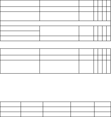
Bradycardia/CRT
General ICD therapy
Timing: Basic rate day/night and rate hystereses
Timing: AV delay
Parameter Range of values Standard
VR
DX
DR
HF
ICD therapy OFF; ON ON xxxx
Programs Display standard program;
Display safe program;
Display first interrogated
program; Individual 1,2,3
–xxxx
Parameter Range of values Standard
VR
DX
DR
HF
Basic rate 30 ... (5) ... 100 ... (10)
... 160 bpm
40 bpm x x
60 bpm x x
Night rate OFF; 30 ... (5) ... 100 bpm OFF x x x x
Begin of night 00:00 ... (00:01)
... 23:59 hh:mm
06:00
hh:mm
xxxx
End of night 22:00
hh:mm
Rate hysteresis OFF
-5 ... (-5) ... -25 ... (-20)
... -65 bpm
OFF x x x x
Scan/repetitive OFF; ON ON x x x x
Parameter Range of values Standard
VR
DX
DR
HF
AV dynamics Low; Medium; High; Fixed;
(Individual)
Low x x x
AV delay (1 or 2) after:
– Pacing 15; 40 ... (5) ... 350 ms – x x x
– Sensing Either automatic: AV delay
after pacing + sense com-
pensation
Or: 40 ... (5) ... 350 ms
–
– At rate 1 50 ... (10) ... 130 bpm 60 bpm
– At rate 2 60 ... (10) ... 140 bpm 130 bpm
Sense compensation OFF
-5 ... (-5) ... -120 ms
-40 ms x x
AV hysteresis mode OFF
Positive; Negative; IRSplus
OFF x x
OFF; Positive; Negative OFF x
AV hysteresis (positive) 70; 110; 150; 200 ms 70 ms x x x
AV hysteresis (negative) 10 ... (10) ... 150 ms 50 ms x x x
AV scan and repetitive
(positive)
OFF; ON ON x x x
Parameter Range of values Standard
VR
DX
DR
HF
393467--B_GA_Iforia_ProMRI_mul-02.book Page 14 Friday, November 16, 2012 11:18 AM

en • English
15
Timing: Post-shock pacing
Timing: Upper rate
Timing: Mode switching
Timing: Ventricular pacing
Timing: Refractory periods and blanking periods
Timing: PMT protection
Parameter Range of values Standard
VR
DX
DR
HF
Post shock duration OFF
10 s; 30 s; 1 min; 2 min;
5 min; 10 min
10 s x x x x
Post-shock basic rate 30 ... (5) ... 100 ... (10)
... 160 bpm
60 bpm xxxx
AV delay post-shock 50 ... (10) ... 350 ms 140 ms x x
Ventricular post-shock
pacing
RV; BiV RV x
Parameter Range of values Standard
VR
DX
DR
HF
Upper rate 90 ... (10) ... 160 bpm 130 bpm x x x
Atrial upper rate OFF
175; 200; 240 bpm
200 bpm x x
Parameter Range of values Standard
VR
DX
DR
HF
Intervention rate OFF; 120 ... (10) ... 200 bpm 160 bpm x x x
Onset criterion 3 ... (1) ... 8 (out of 8) 5 x x x
Resolution criterion
Modification of basic rate OFF; 5 ... (5) ... 30 bpm 10 bpm x x x
Mode VDI(R); VDD(R) VDI x x x
DDI(R); DDD(R) DDI x x
After mode switching:
– Rate OFF; 5 ... (5) ... 50 bpm 10 bpm x x x
– Duration 1 ... (1) ... 30 min 1 min
Parameter Range of values Standard
VR
DX
DR
HF
Permanent RV; BiV; LV BiV x
Triggering OFF; RVs; RVs+PVC RVs x
LV T-wave protection OFF; ON ON x
Maximum trigger rate:
– DDD(R) and VDD(R) UTR + 20;
90 ... (10) ... 160 bpm
UTR + 20 x
– DDI(R), VDI(R) and VVI(R) 90 ... (10) ... 160 bpm 130 bpm
Initially paced chamber RV; LV LV x
VV delay after Vp 0 ... (5) ... 100 ms 5 ms x
Parameter Range of values Standard
VR
DX
DR
HF
PVARP AUTO; 175 ... (20) ... 600 ms 225 ms x x x
Blanking after atrial pacing 50 ... (10) ... 100 ms 50 ms x x
LV blanking after RV pacing 80 ms x
RV blanking after LV pacing
Far-field protection after Vs OFF; 25 ... (25) ... 225 ms 75 ms x x x
Far-field protection after Vp 50 ... (25) ... 225 ms 75 ms x x x
Parameter Range of values Standard
VR
DX
DR
HF
PMT detection/termination OFF; ON ON x x x
VA criterion 250 ... (10) ... 500 ms 350 ms x x x
393467--B_GA_Iforia_ProMRI_mul-02.book Page 15 Friday, November 16, 2012 11:18 AM

16
Timing: Rate adaptation via accelerometer
Pacing: Pulse amplitude and pulse width
Pacing: Ventricular capture control
The following parameters apply to Iforia 5/7:
The following parameters apply to the Iforia 3:
Pacing: atrial capture control
LV lead configuration
MRI program
Valid for devices with ProMRI
®
:
Parameter Range of values Standard
VR
DX
DR
HF
Maximum sensor rate 80 ... (10) ... 160 bpm 160 bpm x x x x
Sensor gain AUTO
Very low; Low; Medium;
High; Very high
Mittel x x x x
Sensor threshold Very low; Low; Medium;
High; Very high
Medium xxxx
Rate increase 1; 2; 4; 8 bpm/cycle 2 bpm x x x x
Rate decrease 0.1; 0.2; 0.5; 1.0 bpm/cycle 0.5 bpm x x x x
Parameter Range of values Standard
VR
DX
DR
HF
Pulse amplitude A 0.5 ... (0.25) ... 4.0 ... (0.5)
... 6.0; 7.5 V
2.5 V x x
Pulse amplitude V/RV x x x x
Pulse amplitude LV x
Pulse width A 0.4; 0.5 ... (0.25) ... 1.5 ms 0.4 ms x x
Pulse width V/RV xxxx
Pulse width LV 0.5 ms x
Parameter Range of values Standard
VR
DX
DR
HF
Capture control OFF; ATM; ON ATM x x x x
Threshold test start 2.5 ... (0.5) ... 5.0 V ATM:
2.5 V
ON: 3.5 V
xxxx
Minimum amplitude 1.0 ... (0.25) ... 4.0 V 1.0 V x x x x
Safety margin 1.0; 1.2 V 1.0 V x x x x
Parameter Range of values Standard
VR
DX
DR
HF
Capture control OFF; ATM ATM x x x x
Parameter Range of values Standard
VR
DX
DR
HF
Capture control OFF; ATM ATM x x
Parameter Range of values Standard
VR
DX
DR
HF
LV pacing polarity LV tip -> LV ring;
LV tip -> RV ring;
LV ring -> LV tip;
LV ring -> RV ring;
UNIP
LV tip ->
RV ring
x
LV sensing polarity UNIP; BIPL UNIP x
Parameter Range of values Standard
VR
DX
DR
HF
Mode V00; OFF OFF x x
V00; D00; OFF x x
Basic rate 70 ... (10) ... 160 bpm 90 bpm x x
Ventricular pacing RV; BiV RV x
393467--B_GA_Iforia_ProMRI_mul-02.book Page 16 Friday, November 16, 2012 11:18 AM

en • English
17
Tachycardia
Detection
Therapy: ATP
Therapy: Shock
Parameter Range of values Standard
VR
DX
DR
HF
Interval AT/AF 240 ... 600 ms 300 ms x x x
Interval VT1 OFF; 270 ... (10) ... 600 ms AUS x x x x
Interval VT2 OFF; 270 ... (10) ... 500 ms
Interval VF OFF; 240 ... (10) ... 400 ms 300 ms
Detection counter VT1 10 ... (2) ... 60 26 x x x x
Detection counter VT2 10 ... (2) ... 40 16
Detection counter VF 6 out of 8; 8 out of 12;
10 out of 12; 12 out of 16;
14 out of 16; 16 out of 20;
18 out of 24; 20 out of 24;
20 out of 24; 22 out of 24;
24 out of 30; 28 out of 30
8 out of
12
Redetection counter VT1 10 ... (2) ... 30 20 x x x x
Redetection counter VT2 14
SMART detection VT1/VT2 OFF; ON ON x x x
SMART detection ON:
– Onset VT1/VT2 4 ... (4) ... 32% 20% x x x
– Stability VT1/VT2 8 ... (4) ... 48% 12%
SMART detection OFF:
– Onset VT1/VT2 OFF; 4 ... (4) ... 32% 20% x x x x
– Stability VT1/VT2 OFF; 8 ... (4) ... 48 ms 24 ms
Sustained VT OFF; 1; 2; 3; 5; 10; 20; 30 min OFF x x x x
Forced termination OFF; 1 ... (1) ... 10 min 1 min x x x
Parameter Range of values Standard
VR
DX
DR
HF
ATP type for VT1/VT2 Burst; Ramp OFF x x x x
ATP type for VF OFF; Burst; Ramp Burst x x x x
ATP optimization OFF; ON OFF x x x x
Attempts OFF; 1 ... (1) ... 10 OFF x x x x
Number S1 for VT1/VT2 1 ... (1) ... 10 5 x x x x
Number S1 for VF 8
S1 decrement for VT1/VT2
and for VF
5 ... (5) ... 40 ms 10 ms x x x x
Scan decrement OFF; 5 ... (5) ... 40 ms OFF x x x x
Additional S1 for VT1/VT2 OFF; ON ON x x x x
Ventricular pacing for
VT1/VT2
RV; LV; BiV RV x
Ventricular pacing for VF RV
R-S1 interval for VT1/VT2 70 ... (5) ... 95% 80% x x x x
R-S1 interval for VF 85%
Parameter Range of values
Standard
VR
DX
DR
HF
Number of shocks VT1/VT2 0; 1; 2; 6; 8 8 x x x x
Number of shocks VF 6; 8 8 x x x x
1. Shock for VT1/VT2 OFF
2 ... (2) ... 20 ... (5) ... 40 J
40 J x x x x
2. Shock for VT1/VT2 OFF
4 ... (2) ... 20 ... (5) ... 40 J
40 J x x x x
3rd - nth shock for VT1/VT2 4*40 J; 6*40 J 6*40 J x x x x
1. Shock for VF OFF
2 ... (2) ... 20 ... (5) ... 40 J
40 J x x x x
393467--B_GA_Iforia_ProMRI_mul-02.book Page 17 Friday, November 16, 2012 11:18 AM

18
Sensing
Sensitivity and thresholds
Diagnostics
The following can be set:
The following can additionally be set for Iforia 7:
2. Shock for VF OFF
4 ... (2) ... 20 ... (5) ... 40 J
40 J x x x x
3rd - nth Shock for VF 4*40 J; 6*40 J 6*40 J x x x x
For shock in VT1/VT2 and VF:
Confirmation OFF; ON ON xxxx
Polarity Normal; Reverse;
Alternating
Normal
Waveform Biphasic; Biphasic 2 Biphasig
Shock path RV -> ICD+SVC
RV -> ICD
RV -> SVC
RV->
ICD+SVC
xxx
RV -> ICD x
Parameter Range of values Standard
VR
DX
DR
HF
Sensing A STD; OFF; IND STD x x x
Sensing RV STD; TWS; VFS; IND STD x x x x
Sensing LV STD; OFF; IND STD x
Upper threshold RV 50; 75 % 50% x x x x
Upper threshold LV 50; 75 % 50% x
Upper threshold duration
after detection
110; 150 ... (50) ... 500 ms
VFS: 110 ms
350 ms x x x x
Upper threshold duration
after pacing
400 ms
Lower threshold RV 25; 50% 25% x x x x
T-wave suppression
after pacing
OFF; ON OFF x x x x
Parameter Range of values
Standard
VR
DX
DR
HF
Minimum threshold A 0.2 ... (0.1) ... 2.0 mv 0.4 mv x x x
Minimum threshold RV 0.5 ... (0.1) ... 2.5 mv 0.8 mv x x x x
Minimum threshold LV 0.5 ... (0.1) ... 2.5 ... (0.5)
... 5.0 mv
1.6 mv x
Parameter Range of values
VR
DX
DR
HF
Standard
For AT/AF OFF; ON
For Iforia 7: Extended ON
xxxON
For SVT OFF; ON xxxON
Periodic recording When Home Monitoring OFF:
OFF; 30 ... (30) ... 180 days
xxxx90 days
IEGM configuration RA, RV, LV
RA, RV, FF
FF; RV; LV
xRA, RV,
LV
Parameter Range of values
VR
DX
DR
HF
Standard
Start resting period 0:00 ... (1:00) ... 23:00 hh:mm x x x x 2:00
hh:mm
Duration of resting period 0.5 ... (0.5) ... 12 h x x x x 4 h
AV delay modification in
sensing test
OFF; 300 ms x x x 300 ms
Thoracic impedance (TI) OFF, ON x x x x OFF
Parameter Range of values Standard
VR
DX
DR
HF
393467--B_GA_Iforia_ProMRI_mul-02.book Page 18 Friday, November 16, 2012 11:18 AM
en • English
19
Home Monitoring
Only applies to Iforia 3
Technical Data
Mechanical Characteristics
Housing
Devices with a DF-1/IS-1 header:
Materials in contact with body tissue
•
Housing: Titanium
•
Header: Epoxy resin
•
Blind plug and silicone plug: Silopren
X-ray identification
NT
Electrical Characteristics
Standards
The specifications are made according to EN 45502-2-2:2008.
Measuring conditions
If not indicated otherwise, all specifications refer to the following conditions:
•
Ambient temperature: 37 ºC ± 2 °C
•
Pacing/sensing: 500 Ω ± 1%
•
Shock: 50 Ω ± 1%
Factory settings
•
Arrhythmia zones VT1, VT2, VF: OFF
•
Antibradycardia pacing: OFF
•
Home Monitoring: OFF
Telemetry data
•
Nominal carrier frequency: 403.6 MHz
•
Maximum power of transmission: < 25 µW (-16 dBm)
International radio certification
Devices with BIOTRONIK Home Monitoring
®
are equipped with an antenna for wireless
communication.
Telemetry data for Canada and the USA:
This device must neither interfere with meteorological and earth resources technology
satellites nor with meteorological stations working in the 400,150 to 406,000 MHZ band,
and it must accept any interference received, including interference that may cause
undesired operation.
•
This device will be registered with Industry Canada under the following number:
IC: 4708A-TACHNXT
The code IC in front of the certification/ registration number only indicates that the
technical requirements for Industry Canada are met.
•
This device will be registered with Federal Communications Commission under the
following number:
FCC ID: QRITACHNXT
Telemetry data for Japan:
Pursuant to the Japanese Radio Act, this device has been granted a designation number
according to the “Ordinance concerning the Technical Regulations Conformity Certifi-
cation etc. of Specified Radio Equipment” Article 2-1-8.
•
R: 202-SMA026
Parameter Range of values Standard
VR
DX
DR
HF
Home Monitoring OFF; ON OFF x x x x
Time of transmission STD; 00:00 ... (01:00) ...
23:00 hh:mm
STD x x x x
IEGM for:
– Therapy episodes OFF; ON ON x x x x
– Monitoring episodes
Ongoing atrial episode OFF; 6, 12, 18 h 12 h x x x
Parameter Range of values Standard
VR
DX
DR
HF
Cycle duration OFF; 30, 60, 90, 120, 180 days 30 days x x x x
Transmission date: XX.XX.XXXX Follow-
up
+ 7 days
xxxx
Type Connection W x H x D in mm Volume in ccm Mass in g
VR, DX, DR DF-1 65 x 55 x 11 31 80
HF DF-1 65 x 58.5 x 11 33 80
393467--B_GA_Iforia_ProMRI_mul-02.book Page 19 Friday, November 16, 2012 11:18 AM
20
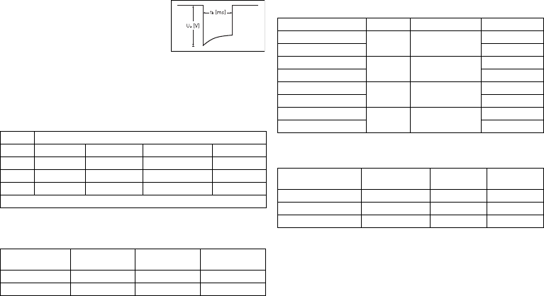
Pulse form
The pacing pulse has the following form:
The pulse amplitude reaches its maximum value at
the beginning of the pulse (Ua). With increasing
pacing duration (tb), the pulse amplitude is reduced
dependent on the pacing impedance.
Resistance to interference
•
Note on device type DX The EMC requirements are met as long as atrial sensitivity
is set to 1.0 mV (factory settings) or values ≥ 1.0 mV. Measures must be taken to
assure interference-free therapy if more sensitive values are set.
•
Note on device type HF: In the case of unipolar sensing, the requirement for inter-
ference voltages of ≤ 0.3 mV (tip to tip) is met.
Common mode rejection
ATP amplitude
A burst was measured at 500 Ω, an amplitude of 7.5 V (tolerance ±1.5 V), pulse width of
1.5 ms, R-S1 interval of 300 ms and an S1 count of 5:
Automatic sensitivity setting
Measurement of actual values and test signal wave shape: standard triangle. For the
device type DX, the programmed atrial sensitivity is intensified by a factor of 4.
Shock energy / peak voltage
With shock path: RV to housing + SVC
Rate Common mode rejection ratio
Atrium: DX* Atrium: DR, HF V right: VR, DR, HF V left: HF
16.6 Hz 58 dB 53 dB 64 dB 66 dB
50 Hz 55 dB 55 dB 64 dB 66 dB
60 Hz 56 dB 56 dB 64 dB 68 dB
* only devices with a DF-1/IS-1 connection.
ATP amplitude Measured
minimum Measured
maximum Mean value
RV 7.67 V 7.67 V 5.00 V
LV 7.67 V 7.67 V 4.99 V
Sensitivity Value Tolerance Measured value
A: positive 0.2 mV 0.2 ... 0.5 0.24 mV
A: negative 0.24 mV
DX: A: positive 0.2 mV 0.2 ... 0.52
(0.05 to 0.13)
0.05 mV
DX: A: negative 0.05 mV
RV: positive 0.5 mV 0.3 ... 0.7 0.48 mV
RV: negative 0.40 mV
LV: positive 0.5 mV 0.3 ... 0.7 0.48 mV
LV: negative 0.56 mV
Shock energy
(Tolerance) Tolerance peak
voltage Measured value
Shock energy Measured value
Peak voltage
1 J (0.7 ... 1.18) 90 ... 120 V 0.84 J 100 V
20 J (16.9 ... 20.9) 440 ... 480 V 18.1 J 469 V
40 J (33.8 ... 41.4) 620 ... 690 V 36.9 J 667 V
393467--B_GA_Iforia_ProMRI_mul-02.book Page 20 Friday, November 16, 2012 11:18 AM

en • English
21
Battery Data
Battery characteristics
The following data is provided by the manufacturers:
Storage period
The storage period affects the battery service time.
•
Devices should be implanted within 19 months between the date of manufacture
and the use by date (indicated on the package).
•
If the ICD is implanted shortly before the use by date, the expected service time
may be reduced by up to 16 months.
Calculation of service times
•
The services times have been calculated as follows – in all chambers depending on
the device type:
—
Pulse amplitude: 2.5 V
—
Pulse width: 0.4 ms
—
Pacing impedance: 500 Ω
—
Basic rate: 60 bpm
—
Home Monitoring: ON, 1 device message each day and 12 transmissions of an
IEGM online HD per year
—
Diagnostic functions and recordings: permanently set
•
Capacitor reforming is performed 4 times per year and therefore at least
4 maximum charges for shocks have to be assumed per year even if less than 4 are
delivered.
Calculation of the number of shocks
Calculation of the number of shocks:
Longevity [in years] x number of shocks per year
Iforia 3/5 VR-T
Service times with GB 2992 or LiS 3410 RA battery:
Iforia 5 VR-T DX
Service times with GB 2992 or LiS 3410 RA battery:
Manufacturer GREATBATCH, INC.
Clarence, NY 14031 LITRONIK GmbH & Co
01796 Pirna, Germany
Battery type GB 2992 LiS 3410 RA
Battery ID number shown on the
programmer
34
Device type VR, (DX), DR, HF
Battery voltage at ERI 2.5 V 2.85 V
Charge time at BOS 8 s 8 s
Charge time at ERI 10 s 10 s
Usable capacity until ERI Iforia 3/5: 1390 mAh
Iforia 7: 1600 mAh
1390 mAh
Usable capacity until EOS 1730 mAh 1520 mAh
Stimulation Longevity [in years] at number of shocks per year
4 8 121620
0%
10.42 8.39 7.01 6.03 5.28
15%
10.14 8.20 6.89 5.93 5.21
50%
9.55 7.81 6.60 5.72 5.05
100%
8.81 7.31 6.24 5.45 4.83
Stimulation Longevity [in years] at number of shocks per year
4 8 121620
0%
9.48 7.76 6.57 5.70 5.03
15%
9.24 7.61 6.46 5.61 4.96
50%
8.75 7.26 6.21 5.42 4.81
100%
8.12 6.83 5.89 5.17 4.62
393467--B_GA_Iforia_ProMRI_mul-02.book Page 21 Friday, November 16, 2012 11:18 AM

22
Iforia 3/5 DR-T
Service times with GB 2992 or LiS 3410 RA battery:
Iforia 3/5 HF-T
Service times with GB 2992 or LiS 3410 RA battery:
Iforia 7 VR-T
Service times with GB 2992 battery:
Iforia 7 VR-T DX
Service times with GB 2992 battery:
Iforia 7 DR-T
Service times with GB 2992 battery:
Iforia 7 HF-T
Service times with GB 2992 battery:
Stimulation Longevity [in years] at number of shocks per year
48121620
0%
9.48 7.76 6.57 5.70 5.03
15%
9.02 7.45 6.35 5.53 4.89
50%
8.10 6.81 5.88 5.17 4.61
100%
7.08 6.07 5.32 4.73 4.26
Stimulation Longevity [in years] at number of shocks per year
48121620
0%
8.78 7.29 6.23 5.44 4.82
15%
8.21 6.89 5.94 5.21 4.65
50%
7.14 6.12 5.35 4.76 4.28
100%
6.01 5.27 4.69 4.23 3.85
Stimulation Longevity [in years] at number of shocks per year
48121620
0%
11.78 9.52 7.98 6.87 6.03
15%
11.48 9.32 7.84 6.76 5.95
50%
10.81 8.87 7.52 6.53 5.76
100%
9.99 8.31 7.11 6.21 5.52
Stimulation Longevity [in years] at number of shocks per year
48121620
0%
10.73 8.82 7.48 6.50 5.74
15%
10.48 8.65 7.36 6.40 5.66
50%
9.92 8.26 7.08 6.19 5.50
100%
9.22 7.77 6.71 5.91 5.27
Stimulation Longevity [in years] at number of shocks per year
48121620
0%
10.73 8.82 7.48 6.50 5.74
15%
10.22 8.47 7.23 6.31 5.59
50%
9.20 7.76 6.70 5.90 5.27
100%
8.05 6.92 6.07 5.40 4.87
Stimulation Longevity [in years] at number of shocks per year
48121620
0%
9.96 8.29 7.10 6.20 5.51
15%
9.33 7.85 6.77 5.95 5.31
50%
8.12 6.97 6.11 5.43 4.89
100%
6.85 6.01 5.36 4.83 4.40
393467--B_GA_Iforia_ProMRI_mul-02.book Page 22 Friday, November 16, 2012 11:18 AM
en • English
23
Legend for the Label
Label on the package
The label icons symbolize the following:
Manufacturing date Use by
Temperature limit Order number
Serial number Product identification
number
Dangerous voltages! CE mark
Contents Follow the instructions for
use
Sterilized with ethylene oxide
Do not resterilize Single use only.
Do not re-use!
Do not use if packaging is
damaged
Non-sterile
Transmitter with non-ionizing radiation at
designated frequency
STERILIZE
2
NON
STERILE
Label icon on devices with ProMRI
®
:MR conditional: Patients who have
a system with devices labeled with this
symbol on the packaging can be exam-
ined using an MRI scan under precisely
defined conditions.
Example
Device: NBG code and compatible leads
Example
Factory settings for therapy: OFF
Screwdriver
Example of DF-1/IS-1 header
Bipolar IS-1 connector
Unipolar IS-1 connector
Unipolar DF-1 connector
393467--B_GA_Iforia_ProMRI_mul-02.book Page 23 Friday, November 16, 2012 11:18 AM

24
de • Deutsch
Produktbeschreibung
Medizinische Zweckbestimmung
Bestimmungsgemäße Anwendung
Iforia 3/5/7 gehört zu einer Familie von implantierbaren Kardiovertern-Defibrillatoren
(ICD). Primäres Ziel der Therapie ist die Verhinderung eines plötzlichen Herztodes.
Weiterhin sind die Behandlung von bradykarden Rhythmusstörungen und die Herz-
insuffizienztherapie mit multisite-ventrikulärer Stimulation möglich.
Die Implantation eines ICDs ist eine symptomatische Therapie mit folgenden Zielen:
•
Terminierung von spontan auftretendem Kammerflimmern (VF) durch Schock-
abgabe
•
Terminierung von spontanen ventrikulären Tachykardien (VT) durch antitachykarde
Stimulation (ATP); bei ineffektivem ATP oder hämodynamisch nicht tolerierten VTs
mit Schockabgabe
•
Kardiale Resynchronisation durch multisite-ventrikuläre Stimulation (3-Kammer-
Implantate)
•
Kompensation von Bradykardien durch ventrikuläre (1-Kammer-Implantate) oder
AV-sequentielle Stimulation (DX, 2- und 3-Kammer-Implantate)
Diagnose- und Therapieformen
Das Implantat überwacht den Herzrhythmus und ein von ventrikulären Tachyarrhyth-
mien verursachter Herz-Kreislauf-Stillstand wird automatisch detektiert und termi-
niert. Alle wesentlichen Therapieansätze aus Kardiologie und Elektrophysiologie sind
enthalten. BIOTRONIK Home Monitoring
®
ermöglicht Ärzten ein Therapiemanagement
rund um die Uhr.
Vorausgesetzte Fachkenntnisse
Außer den medizinischen Grundlagen sind detaillierte Kenntnisse über die Funktions-
weise und die Einsatzbedingungen eines Implantatsystems erforderlich.
•
Nur medizinische Fachkräfte mit diesen besonderen Kenntnissen dürfen Implan-
tate bestimmungsgemäß anwenden.
•
Wenn diese Kenntnisse nicht vorhanden sind, müssen Anwender geschult werden.
Indikationen
Iforia kann mit Hilfe von antitachykarder Stimulation und Defibrillation lebensbedroh-
liche ventrikuläre Arrhythmien behandeln.
Für Implantate von BIOTRONIK gelten die allgemein anerkannten Methoden der Diffe-
rentialdiagnostik, die Indikationen sowie die Empfehlungen für die ICD-Therapie;
Orientierung bieten die Leitlinien kardiologischer Gesellschaften.
Wir empfehlen, die von der DGK (Deutsche Gesellschaft für Kardiologie, Herz- und
Kreislaufforschung) und der ESC (European Society of Cardiology) veröffentlichten
Indikationen zu beachten. Desgleichen die der Heart Rhythm Society (HRS), des Ame-
rican College of Cardiology (ACC), der American Heart Association (AHA) sowie die
anderer nationaler Kardiologieverbände.
1- und 2-Kammer
1- und 2-Kammer-ICDs sind indiziert bei Patienten mit folgender Gefährdung:
•
Plötzlicher Herztod aufgrund ventrikulärer Arrhythmien
3-Kammer
3-Kammer-ICDs sind indiziert bei Patienten mit folgenden Gefährdungen:
•
Plötzlicher Herztod aufgrund ventrikulärer Arrhythmien
•
Herzinsuffizienz mit ventrikulärer Asynchronie
Auch zur Primärprophylaxe für Herzinsuffizienzpatienten ist Iforia indiziert.
Kontraindikationen
Bekannte Kontraindikationen:
•
Durch vorübergehende oder reversible Störungen verursachte Tachyarrhythmien,
beispielsweise Vergiftungen, Elektrolytungleichgewicht, Hypoxie, Sepsis, akuter
Herzinfarkt
•
So häufige VT oder VF, dass die Therapien die Batterie des Implantats unverhältnis-
mäßig schnell entladen würden
•
VT mit klinisch geringer oder nicht relevanter Symptomatik
•
VT oder VF mit operativ behebbarer Ursache
•
Begleiterkrankungen, die die Prognose deutlich limitieren
•
Beschleunigter idioventrikulärer Rhythmus
393467--B_GA_Iforia_ProMRI_mul-02.book Page 24 Friday, November 16, 2012 11:18 AM
de • Deutsch
25
Systemübersicht
Implantatfamilie
Die vollständige Implantatfamilie Iforia 3/5/7 besteht aus mehreren Implantattypen mit
DF-1/IS-1Anschluss.
1-Kammer: VR-T und VR-T DX (nur Implantate mit DF-1/IS-1-Anschluss); 2-Kammer:
DR-T; 3-Kammer: HF-T. Nicht in jedem Land sind alle Implantattypen erhältlich.
Implantat
Das Gehäuse des Implantats ist aus biokompatiblem Titan, von außen verschweißt und
somit hermetisch versiegelt. Die ellipsoide Form erleichtert das Implantieren in den
Brustmuskelbereich. Im Anschlussblock des Implantats befinden sich die Anschlüsse
für bipolare Stimulation und Wahrnehmung (beim 3-Kammer-Implantat auch unipo-
lare) sowie für die Schockabgabe. Das Gehäuse dient bei der Schockabgabe oder bei
unipolarer Elektrodenkonfiguration als potenzieller Gegenpol.
Elektrodenanschluss DF-1/IS-1
Die Beschriftung des Implantats gibt Auskunft über die möglichen Elektroden-
anschlüsse je Implantattyp und über die Anordnung der Anschlüsse:
Elektroden
Die Elektroden von BIOTRONIK sind mit biokompatiblem Silikon ummantelt. Sie sind
flexibel zu manövrieren, langzeitstabil und für aktive oder passive Fixierung ausge-
stattet. Sie werden mit Hilfe eines Einführbestecks implantiert. Einige Elektroden sind
zur besseren Gleitführung mit Polyurethan beschichtet. Elektroden mit Steroiden
reduzieren entzündliche Prozesse. Die fraktale Ausführung der Elektroden sorgt für
niedrige Reizschwellen. BIOTRONIK bietet Adapter an, um bereits liegende Elektroden
an neue Implantate anzuschließen.
Telemetrie
Die telemetrische Kommunikation zwischen Implantat und Programmiergerät ist nach
der Initialisierung sowohl mittels Auflage eines Programmierkopfs (PGH, programming
head) als auch mittels RF-Telemetrie (Hochfrequenztelemetrie) möglich; diese Funk-
tion heißt bei BIOTRONIK SafeSync
®
.
Programmiergerät
Implantiert und nachgesorgt wird mit dem transportablen Programmiergerät von
BIOTRONIK: Es gibt eines mit integrierter RF-Telemetrie und eines mit separatem
SafeSync Module. Mit Hilfe des Programmiergeräts wird bei der Implantation das aktu-
elle Implantatprogramm auf das Implantat übertragen. Es können die Reizschwellen
festgestellt und alle Tests während einer Präsenznachsorge durchgeführt werden. Das
Programmiergerät dient darüber hinaus der Einstellung von Modus und Parameter-
kombinationen sowie der Abfrage und Speicherung von Daten aus dem Implantat. Auf
dem Farbdisplay werden gleichzeitig kabelloses EKG, IEGM, Marker und Funktionen
angezeigt.
Modi
Die Einstellung des Modus hängt von der individuellen Diagnose ab:
NBD- und NBG-Codes
VVE lautet der NBD-Code für den antitachykarden Modus der 1-, 2- und 3-Kammer-
Implantate:
VR DX DR HF
Anschluss Stecker Konfiguration Implantationsort Implantattyp
RV DF-1 Schockwendel Rechter Ventrikel VR, DX, DR, HF
SVC DF-1 Schockwendel Vena cava superior VR, DX, DR, HF
RA IS-1 Bipolar Atrium DX, DR, HF
(R)V IS-1 Bipolar (Rechter) Ventrikel VR, DX, DR, HF
LV IS-1 Unipolar, bipolar Linker Ventrikel HF
DF-1
RV
DF-1
SVC
IS-1
RV
DF-1
RV
DF-1
SVC IS-1
RA
IS-1
RV
DF-1
RV
DF-1
SVC IS-1
RA
IS-1
RV
DF-1
RV
DF-1
SVC IS-1
RA
IS-1
RV
IS-1
LV
Implantattyp Modi
VR VVI; VVIR; V00; AUS
DX VDD; VDDR; VDI; VDIR; VVI; VVIR; V00; AUS
DR, HF DDD; DDDR; DDI; DDIR; VDD; VDDR; VDI; VDIR
VVI; VVIR; AAI; AAIR; V00; D00; AUS
V Schock im Ventrikel
V Antitachykarde Stimulation (ATP) im Ventrikel
E Detektion durch IEGM-Auswertung
393467--B_GA_Iforia_ProMRI_mul-02.book Page 25 Friday, November 16, 2012 11:18 AM

26
DDDR lautet der NBG-Code für den antibradykarden Modus des 2-Kammer-Implantats:
DDDRV lautet der NBG-Code für den antibradykarden Modus des 3-Kammer-Implan-
tats:
VDDR lautet der NBG-Code für den antibradykarden Modus des 1-Kammer-DX-Implan-
tats:
VVIR lautet der NBG-Code für die antibradykarden Stimulationsarten des
1-Kammer-Implantats:
BIOTRONIK Home Monitoring
®
Über die effektive Stimulationstherapie hinaus stellt BIOTRONIK ein komplettes Thera-
piemanagement zur Verfügung:
•
Beim Home Monitoring werden diagnostische und therapeutische Informationen
sowie technische Daten des Implantats automatisch und drahtlos mittels einer
Antenne im Anschlussblock des Implantats an ein stationäres oder mobiles Patien-
tengerät gesendet. Vom Patientengerät werden die Daten verschlüsselt und via
Mobilfunknetz an das BIOTRONIK Service Center gesendet.
•
Die empfangenen Daten werden entschlüsselt und ausgewertet; jeder Arzt kann für
jeden Patienten individuell einstellen, nach welchen Kriterien ausgewertet werden
und wann er per E-Mail, SMS oder Fax benachrichtigt werden soll.
•
Die Ergebnisse dieser Auswertung werden für die behandelnden Ärzte auf der
geschützten Internetplattform namens Home Monitoring Service Center (HMSC)
übersichtlich dargestellt.
•
Die Datenübertragung vom Implantat aus erfolgt mit einer täglichen Implantat-
nachricht.
•
Implantatnachrichten, die auf besondere Ereignisse im Herzen oder im Implantat
hinweisen, werden sofort weitergeleitet.
•
Jederzeit kann vom Programmiergerät aus zur Sofortkontrolle der Home-Monito-
ring-Funktion eine Testnachricht initiiert werden.
Gebrauchsanweisungen
Folgende Gebrauchsanweisungen informieren über die Anwendung von Implantat-
systemen:
•
Gebrauchsanweisung zum Implantat
•
Gebrauchsanweisung zum HMSC
•
Gebrauchsanweisungen zum Programmiergerät und zum SafeSync Module
•
Gebrauchsanweisung zu Implantatprogrammen als Software-Hilfe auf der
Benutzeroberfläche und als PDF-Datei in der Manual Library auf
www.BIOTRONIK.com
•
Gebrauchsanweisungen zu den Elektroden
•
Gebrauchsanweisungen zu Kabeln, Adaptern und Zubehör
D Stimulation im Atrium und im Ventrikel
D Wahrnehmung im Atrium und im Ventrikel
D Impulsinhibierung und Impulstriggerung
R Frequenzadaption
D Stimulation im Atrium und im Ventrikel
D Wahrnehmung im Atrium und im Ventrikel
D Impulsinhibierung und Impulstriggerung
R Frequenzadaption
V Multisite-Stimulation in beiden Ventrikeln
V Stimulation im Ventrikel
D Wahrnehmung im Atrium und im Ventrikel
D Impulsinhibierung und Impulstriggerung
R Frequenzadaption
V Stimulation im Ventrikel
V Wahrnehmung im Ventrikel
I Impulsinhibierung im Ventrikel
R Frequenzadaption
393467--B_GA_Iforia_ProMRI_mul-02.book Page 26 Friday, November 16, 2012 11:18 AM

de • Deutsch
27
Bestellnummern Iforia mit DF-1/IS-1-Anschluss
Nicht alle Implantattypen sind in allen Ländern erhältlich:
Bestellnummern Iforia ProMRI mit DF-1/IS-1-Anschluss
Nicht alle Implantattypen sind in allen Ländern erhältlich:
Lieferumfang
In der Lagerverpackung befinden sich:
•
Sterilverpackung mit Implantat
•
Seriennummernaufkleber
•
Patientenausweis
•
Garantieheft
•
Gebrauchsanweisung zum Implantat
In der Sterilverpackung befinden sich:
•
Implantat, gegebenenfalls Blindstecker DF-1 und beim Implantattyp HF
Blindstecker IS-1
•
Schraubendreher
Therapie- und Diagnostikfunktionen
Diagnostikfunktionen
•
Daten der Implantation und der letzten Abfragen und Nachsorgen werden ebenso
aufgezeichnet wie Arrhythmieepisoden; sie werden zusammen mit weiteren Daten
gespeichert, um sowohl Patienten als auch Implantatzustand jederzeit beurteilen
zu können.
•
Zur Kontrolle der Funktionsfähigkeit der Elektroden wird die Impedanz im
Implantat automatisch mittels unterschwelliger Impulse gemessen.
•
Funktion kabelloses EKG: Bei allen Implantattypen kann eine Far-field-Ableitung
ohne externe Elektroden zwischen rechtsventrikulärer, distaler Schockwendel und
Gehäuse gemessen werden, was – je nach Situs – der EKG-Ableitung II oder III nach
Einthoven entspricht.
•
Bei Präsenznachsorgen werden nach dem Herstellen einer Telemetrieverbindung
während des Testablaufs das kabellose EKG und das IEGM mit Markern angezeigt.
Antitachykarde Stimulation
•
Der ICD kann ventrikuläre Tachykardien mit antitachykarder Stimulation (ATP)
behandeln; auch in der VF-Zone kann ATP One Shot abgegeben werden, wenn das
Stabilitätskriterium vor der Schockabgabe (monomorphe schnelle VTs) erfüllt ist.
•
Je nach Implantattyp enthält das Implantatprogramm neben den ICD-Funktionen
auch alle Schrittmacher-Funktionen für 1, 2 oder 3 Kammern. Der Herzrhythmus
wird kontinuierlich überwacht, jede Arrhythmie wird entsprechend der Herz-
frequenz und einstellbarer Detektionskriterien klassifiziert. Abhängig von den
voreingestellten Werten wird sowohl antibradykarde als auch antitachykarde
Therapie inhibiert oder abgegeben.
Kardioversion, Defibrillation
•
Der ICD kann ventrikuläre Tachyarrhythmien mit Kardioversion und/oder Defibril-
lation behandeln. Schockpolarität und -energie lassen sich individuell einstellen;
Schockenergien zwischen 2,0 und 40 J sind möglich. Der ICD kann sich vor Abgabe
des Schocks das Andauern der Tachyarrhythmie bestätigen lassen; in diesem Zeit-
raum kann das Implantat eine spontane Konversion der Tachyarrhythmie identifi-
zieren und den Ladevorgang gegebenenfalls abbrechen.
•
Zwischen den unterschiedlichen Schockwendeln (SVC/RV) und/oder dem Gehäuse
lassen sich die Schockpfade einstellen.
Antibradykarde Stimulation und CRT
•
Innovative Frequenzhysteresen, automatische Sensorfunktionen und ein Nacht-
programm fördern den Eigenrhythmus des Patienten, vermeiden Überstimulation
und erleichtern eine Anpassung des Implantats an die individuellen Bedürfnisse
des Patienten.
•
Die Einstellung einer oberen Grenzfrequenz fürs Atrium vermeidet unspezifische
atriale Stimulation und verringert somit die Gefahr schrittmacherinduzierter
Tachykardien.
Iforia 3 Iforia 5 Iforia 7
VR-T 383586 383583 390081
VR-T DX — 383597 390093
DR-T 383570 383567 390067
HF-T 383554 383551 390054
Iforia 5 ProMRI Iforia 7 ProMRI
VR-T 390119 390083
VR-T DX 390123 390095
DR-T 390115 390069
HF-T 390111 390056
393467--B_GA_Iforia_ProMRI_mul-02.book Page 27 Friday, November 16, 2012 11:18 AM
28
•
Positive AV-Hysterese-Funktionen unterstützen die intrinsische Überleitung und
damit den natürlichen Kontraktionsablauf. Negative AV-Hysterese-Funktionen
unterstützen die kardiale Resynchronisationstherapie mittels Aufrechterhaltung
der Stimulation in Belastungssituationen.
•
3-Kammer-Implantate haben zur Resynchronisation der Ventrikel Funktionen zur
multisite-ventrikulären Stimulation mit möglichen VV-Zeit in beiden Richtungen.
•
Damit bei einer linksseitigen Reizschwellenerhöhung oder ungewollter Phrenicus-
Stimulation keine erneute Operation nötig ist, kann man bei einem 3-Kammer-
Implantat für die linksventrikuläre Elektrode unterschiedliche Stimulationspolari-
täten einstellen.
•
Es gibt eine automatische Amplitudensteuerung für den rechten und linken
Ventrikel mit automatischer Verfolgung der Reizschwelle oder Reizschwellen-
überwachung (ATM) zwecks Trendanalyse.
Bei Iforia 3 wird die Reizschwelle lediglich gemessen.
Programme speichern
Die Einstellungen der Parameter lassen sich in 3 individuellen Therapieprogrammen
speichern.
Funktionen von Home Monitoring
•
Automatisch sendet das Implantat einmal täglich Informationen an das Patienten-
gerät. Zusätzlich sendet es automatisch auf Ereignisse bezogene Nachrichten, die
sofort an das Service Center weitergeleitet werden. Außerdem können Testnach-
richten mit Hilfe des Programmiergeräts initiiert werden.
•
Es können Termine für Home-Monitoring-gestützte Nachsorgen via HMSC geplant
werden. Gilt für Iforia 5/7.
•
Wichtige medizinische Informationen in den Implantatnachrichten sind unter
anderem folgende:
—
Atriale und ventrikuläre Arrhythmien
—
Elektrodenrelevante Parameter im Atrium und Ventrikel: Reizschwellen, Wahr-
nehmungsamplituden, Impedanzen
—
Aktuelle Statistiken
—
IEGM-Online HD
®
mit bis zu 3 Kanälen in hoher Auflösung (High Definition)
Allgemeine Sicherheitshinweise
Betriebsbedingungen
Aufbewahrung bei Transport und Lagerung
•
Implantate dürfen nicht in der Nähe von Magneten oder elektromagnetischen Stör-
quellen transportiert oder gelagert werden.
•
Auswirkungen der Lagerdauer beachten, siehe Batteriedaten.
Auslieferung im Transportmodus
Das Implantat wird zum Schutz der Batterie in einem Transportmodus ausgeliefert; bei
während der Lagerung notwendigen Kondensatorformierungen kann es zu kontrolliert
verlängerten Ladezeiten der Schockkondensatoren kommen.
•
Der Transportmodus wird am Programmiergerät nach dem Laden des Implantat-
programms angezeigt. (Er wird bei der Implantation bei der ersten Messung der
Stimulationsimpedanz deaktiviert.)
Temperatur
Sowohl extrem niedrige als auch hohe Temperaturen wirken sich auf die Betriebszeit
der Batterie im Implantat aus.
•
Zulässig für Transport, Lagerung und Betrieb sind 5 °C bis 45 °C.
Sterile Auslieferung
Implantat und Schraubendreher werden gassterilisiert ausgeliefert. Die Sterilität ist
gewährleistet, wenn Blister und Qualitätskontrollsiegel nicht beschädigt sind.
Sterilverpackung
Implantat und Schraubendreher sind in 2 separat versiegelten Blistern verpackt; der
innere Blister ist auch außen steril, damit er bei der Implantation steril übergeben
werden kann.
Einmalverwendung
Implantat und Schraubendreher sind nur zur Einmalverwendung vorgesehen.
•
Implantat nicht verwenden, wenn die Verpackung beschädigt ist.
•
Implantat nicht resterilisieren und nicht wiederverwenden.
393467--B_GA_Iforia_ProMRI_mul-02.book Page 28 Friday, November 16, 2012 11:18 AM
de • Deutsch
29
Mögliche Komplikationen
Allgemeines zu medizinischen Komplikationen
Für Implantate von BIOTRONIK gelten die in der Fachpraxis allgemein bekannten Kom-
plikationen für Patienten und Implantatsysteme.
•
Komplikationen sind beispielsweise Flüssigkeitsansammlungen in der Implantat-
tasche, Infektionen oder Gewebereaktionen. Maßgebliche Orientierung sind Stand
der Wissenschaft und Technik.
•
Garantieren kann man die Zuverlässigkeit von Antiarrhythmietherapie nicht, auch
wenn während der Tests oder späterer elektrophysiologischer Untersuchungen die
Programme erfolgreich waren. Unter seltenen Umständen können die einge-
stellten Parameter ineffektiv werden. Insbesondere lässt sich nicht ausschließen,
dass Tachykardien induziert oder durch einen Therapieversuch beschleunigt
werden, also langanhaltendes ventrikuläres Flattern oder Flimmern eintritt.
Skelettmuskelpotenziale
Bipolare Wahrnehmung und Kontrolle der Empfindlichkeit werden vom Implantat so
auf das Frequenzspektrum der Herzeigenaktionen abgestimmt, dass Skelettmuskel-
potenziale in der Regel nicht erfasst werden. Dennoch können – vor allem bei sehr
hoher Empfindlichkeit – Skelettmuskelpotenziale als Herzeigenaktionen klassifiziert
werden und – je nach Interferenz – Inhibierung oder Antiarrhythmietherapie bewirken.
Bei unerwünschten Muskelpotenzialen schaltet das Implantat bei Überschreitung der
Interferenzfrequenz auf asynchrone Stimulation.
Mögliche technische Fehlfunktionen
Fehlfunktionen eines Implantatsystems können grundsätzlich nicht ausgeschlossen
werden. Ursachen können unter anderem folgende sein:
•
Elektrodendislokation, Elektrodenbruch
•
Isolierungsdefekte
•
Komponentenfehler des Implantats
•
Batterieerschöpfung
•
Telemetriestörung
Elektromagnetische Interferenzen EMI
Jedes Implantat kann gestört werden, wenn äußere Signale als Eigenrhythmus wahr-
genommen werden oder Messungen die Frequenzanpassung behindern:
•
Implantate von BIOTRONIK sind so konstruiert, dass ihre Beeinflussbarkeit durch
EMI minimal ist.
•
Wegen der vielen Arten und Intensitäten von EMI gibt es keine absolute Sicherheit.
Allgemein geht man davon aus, dass EMI – wenn überhaupt – nur geringfügige
Symptome beim Patienten verursacht.
•
Je nach Stimulationsart und Art der Interferenz können Störquellen zu einer
Impulsinhibierung oder -triggerung, zum Anstieg der sensorabhängigen Stimula-
tionsfrequenz oder zu asynchroner Stimulation führen.
•
Unter ungünstigen Bedingungen, besonders im Rahmen therapeutischer und dia-
gnostischer Maßnahmen, können Störquellen eine so hohe Energie einkoppeln,
dass Gewebe, welches das Implantat oder die Elektrodenspitze umgibt, geschädigt
wird.
Verhalten des Implantats bei EMI
Bei elektromagnetischer Interferenz schaltet das Implantat für die Dauer der Über-
schreitung der Interferenzfrequenz auf asynchrone Stimulation.
Statische magnetische Felder
Der Reedkontakt im Implantat schließt ab einer Feldstärke von 1,8 mT. Fällt das
magnetische Feld unter 1 mT, öffnet sich der Reedkontakt.
Mögliche Risiken
Kontraindizierte Verfahren
Wegen möglicher Schädigung des Patienten oder des Implantats und daraus resultie-
render Funktionsunsicherheit ist die Anwendung folgender Verfahren kontraindiziert:
•
Therapeutischer Ultraschall: Schädigung des Patienten durch übermäßige Erwär-
mung des Körpergewebes im Bereich des Implantatsystems
•
Transkutane elektrische Nervenstimulation
•
Hyperbare Sauerstofftherapie
•
Druckbelastungen über Normaldruck
Risikobehaftete Therapie- und Diagnoseverfahren
Wenn für diagnostische oder therapeutische Zwecke elektrischer Strom von einer
externen Quelle durch den Körper geleitet wird, können das Implantat gestört und der
Patient gefährdet werden.
Bei diathermischen Verfahren wie zum Beispiel Elektrokauterisierung, HF-Ablation
oder HF-Chirurgie ist eine Induktion von Arrhythmien oder Kammerflimmern möglich.
Bei zum Beispiel Lithotripsie ist eine schädliche Wärmewirkung möglich. Auswir-
kungen auf das Implantat kann man manchmal nicht sofort feststellen.
393467--B_GA_Iforia_ProMRI_mul-02.book Page 29 Friday, November 16, 2012 11:18 AM

30
Wenn risikobehaftete Verfahren nicht zu vermeiden sind, gilt deshalb immer:
•
Patienten elektrisch isolieren.
•
Detektionsfunktion des ICDs ausschalten; die Schrittmacherfunktion – gegebenen-
falls auf asynchrone Modi umstellen – kann aktiv bleiben.
•
Keine Energie in die Nähe des Implantatsystems einbringen.
•
Zusätzlich peripheren Puls des Patienten kontrollieren.
•
Patienten bei und nach jedem Eingriff überwachen.
Externe Defibrillation
Das Implantat ist gegen die Energie geschützt, die eine externe Defibrillation norma-
lerweise induziert. Externe Defibrillation kann jedoch jedes Implantat schädigen.
Insbesondere Strominduktion in die implantierten Elektroden kann Nekrosen im
Einwachsbereich hervorrufen, was wiederum zu veränderten Wahrnehmungseigen-
schaften und Reizschwellen führt.
•
Klebeelektroden anterior-posterior oder senkrecht zur Verbindungslinie vom
Implantat zum Herzen sowie mindestens 10 cm vom Implantat und von den implan-
tierten Elektroden entfernt platzieren.
Strahlentherapie
Die Anwendung von therapeutischer Bestrahlung ist wegen möglicher Schädigung des
Implantats und daraus resultierender Funktionsunsicherheit kontraindiziert. Sollte
diese Therapieart dennoch angewendet werden, ist eine vorherige Risiko-Nutzen-
Abwägung unabdingbar. Die Komplexität der Einflussfaktoren – zum Beispiel unter-
schiedliche Strahlenquellen, Implantatvielfalt, Therapiebedingungen – macht es nicht
möglich, Richtlinien zu verabschieden, die eine Strahlentherapie ohne Auswirkungen
auf das Implantat garantieren. Die Norm EN 45502 über aktive implantierbare Medizin-
geräte fordert im Zusammenhang mit therapeutischer ionisierender Strahlung fol-
gende Maßnahmen:
•
Hinweise zu risikobehafteten Therapie- und Diagnoseverfahren beachten.
•
Implantat gegen Strahlen abschirmen.
•
Nach der Strahlenapplikation das Implantatsystem wiederholt auf Funktionsfähig-
keit prüfen.
Magnetresonanztomografie
Magnetresonanztomografie (MRT) ist wegen der damit verbundenen Hochfrequenz-
felder und magnetischen Flussdichten kontraindiziert: Schädigung oder Zerstörung
des Implantatsystems durch starke magnetische Wechselwirkung und Schädigung des
Patienten durch übermäßige Erwärmung des Körpergewebes im Bereich des Implan-
tatsystems.
Unter bestimmten Bedingungen kann man bei Einhaltung vorgeschriebener Maßnah-
men zum Schutz von Patient und Implantatsystem eine Magnetresonanztomografie
durchführen. Bei BIOTRONIK haben Implantate mit der Funktion "MR conditional" die
Kennung ProMRI
®
.
•
Das Handbuch ProMRI
®
– MR-conditional-Implantatsysteme – enthält ausführ-
liche Informationen über die sichere Durchführung einer MRT.
—
Digitales Handbuch von der Website laden:
www.biotronik.com/manuals/manualselection
—
Gedrucktes Handbuch bei BIOTRONIK bestellen.
•
Gilt die Zulassung als MR conditional in Ihrem Land oder Ihrer Region? Aktuelle
Informationen bei BIOTRONIK anfordern.
Implantation
Implantationsablauf
Teile bereitlegen
Folgende der EG-Richtlinie 90/385/EEC entsprechende Teile werden benötigt:
•
Implantat mit Blindstecker und Schraubendreher von BIOTRONIK
•
Elektroden von BIOTRONIK und Einführbesteck
—
1-Kammer-Implantat: eine bipolare ICD-Elektrode mit 1 oder 2 Schockwendeln
für den Ventrikel
—
2-Kammer-Implantat: eine bipolare Elektrode für das Atrium und eine bipolare
ICD-Elektrode für den Ventrikel mit 1 oder 2 Schockwendeln
—
3-Kammer-Implantat: zusätzlich eine uni- oder bipolare LV-Elektrode
•
Zulässige Anschlüsse sind DF-1 und IS-1. Für Elektroden mit anderen Anschlüssen
oder Elektroden anderer Hersteller nur die von BIOTRONIK zugelassenen Adapter
verwenden.
•
Programmiergerät von BIOTRONIK (mit integrierter SafeSync-RF-Telemetrie oder
mit separatem SafeSync Module) und zugelassene Kabel
•
Externes Mehrkanal-EKG-Gerät
•
Für sterile Teile Ersatz in Reserve halten.
Hinweis:
Mit Fragen bei der Risiko-Nutzen-Abwägung bitte an BIOTRONIK wenden.
393467--B_GA_Iforia_ProMRI_mul-02.book Page 30 Friday, November 16, 2012 11:18 AM

de • Deutsch
31
Externen Defibrillator bereithalten
Zur Reaktion auf unvorhersehbare Notfälle oder auf eventuelle Fehlfunktionen des
Implantats:
•
Externen Defibrillator und Paddles oder Klebeelektroden bereithalten.
Implantat auspacken
•
Papierverschluss des äußeren Blisters an der markierten Stelle in Pfeilrichtung
abziehen. Der innere Blister darf nicht von unsterilen Personen oder Instrumenten
berührt werden!
•
Inneren Blister an der Griffmulde anfassen und aus dem äußeren Blister nehmen.
•
Papierverschluss des sterilen inneren Blisters an der markierten Stelle in Pfeil-
richtung abziehen.
Teile prüfen
Beschädigungen an einem der Teile können zu Komplikationen oder Fehlfunktionen
führen.
•
Vor und nach dem Auspacken alle Teile auf Beschädigungen prüfen.
•
Beschädigte Teile austauschen.
•
Der ICD wird mit deaktivierter Tachyarrhythmietherapie ausgeliefert und darf nur
in diesem Zustand implantiert werden.
•
Elektroden dürfen nicht gekürzt werden.
Situs
•
Abhängig von der Anatomie des Patienten und der Elektrodenkonfiguration werden
ICDs in der Regel subpektoral links implantiert.
Ableitströme vermeiden
Während der Implantation müssen Ableitströme zwischen Werkzeugen und dem
Implantat vermieden werden.
•
Patienten elektrisch isolieren.
Unbeabsichtigte Schockabgabe vermeiden
Anschlussblock nicht beschädigen
Für DF-1- und IS-1-Anschlüsse gibt es einen Blindstecker im Anschlussblock; die
zugehörigen Anschlussschrauben müssen sorgfältig angezogen oder gelöst werden.
•
Anschlussschrauben mit dem mitgelieferten Schraubendreher lösen. Nur Schrau-
bendreher mit Drehmomentbegrenzung von BIOTRONIK benutzen!
•
Blindstecker nicht mit Gewalt herausziehen!
•
Im Fall einer notwendigen Elektrodenrevision bei BIOTRONIK sterile Schrauben-
dreher nachbestellen.
Kurzschluss im Anschlussblock vermeiden
Elektrodenstecker an Implantat anschließen
WARNUNG
Inadäquate Therapie wegen defekten Implantats
Wenn ein ausgepacktes Implantat beim Hantieren herunterfällt und auf eine harte
Oberfläche aufschlägt, könnten elektronische Teile beschädigt sein.
•
Ersatzimplantat verwenden.
•
Beschädigtes Implantat an BIOTRONIK schicken.
WARNUNG
Schockabgabe bei aktiviertem ICD
Beim Umgang mit einem aktivierten ICD besteht die Gefahr einer unbeabsichtigten
Schockabgabe.
•
Vor dem Anfassen des Implantats bei Implantation, Implantatwechsel und
Explantation die ICD-Therapie deaktivieren.
WARNUNG
Kurzschluss durch offene Elektrodenanschlüsse
Offene und dadurch nicht elektrolytdichte Anschlüsse im Anschlussblock können
unerwünschte Stromflüsse zum Körper und das Eindringen von Körperflüssigkeit ins
Implantat verursachen.
•
Nicht genutzte Anschlüsse entweder mit den vormontierten Blindsteckern ver-
schlossen lassen oder mit den mitgelieferten Blindsteckern verschließen.
1 Mandrins und Einführhilfen entfernen.
2 DF-1/IS-1-Anschluss:
•
DF-1-Stecker der rechtsventrikulären Schockwendel an RV anschließen.
•
DF-1-Stecker der supraventrikulären Schockwendel an SVC anschließen.
Oder eine subkutane Fingerelektrode an SVC anschließen.
393467--B_GA_Iforia_ProMRI_mul-02.book Page 31 Friday, November 16, 2012 11:18 AM
32
Abstand zwischen Elektroden wahren
Implantieren
Programmierkopf auflegen
Auf dem Programmierkopf (PGH) befindet sich eine schematische Zeichnung des
Implantats. Diese dient als Positionierhilfe bei der Auflage, um eine korrekte Tele-
metrie sicherzustellen.
•
Auf eine richtige Positionierung des PGHs achten.
Telemetrie herstellen
Das Programmiergerät (oder das SafeSync Module) darf maximal 3 m vom Implantat
entfernt sein; am besten befinden sich keine Hindernisse zwischen Patient und Pro-
grammiergerät.
•
Die RF-Telemetrie am Programmiergerät einschalten.
•
Den Programmierkopf etwa 2 s auflegen, bis die erfolgreiche Initialisierung am
Programmiergerät angezeigt wird:
Im Navigator ist das Symbol für SafeSync zu sehen und in der Status-
zeile eine Anzeige für die Signalstärke.
•
Den Programmierkopf weglegen.
ICD-Therapie aktivieren
•
Am Programmiergerät das für den Implantattyp passende Implantatprogramm
laden.
•
ICD-Therapie aktivieren.
3 DF-1/IS-1-Anschluss:
•
Bipolaren IS-1-Stecker Atrium an RA anschließen.
•
Bipolaren IS-1-Stecker rechter Ventrikel an RV anschließen.
•
Uni- oder bipolaren IS-1-Stecker linker Ventrikel an LV anschließen.
4 Elektrodenstecker – ohne Stecker und Zuleitung zu drehen oder zu knicken – in
den Anschlussblock schieben, bis beim DF-1-Stecker die Steckerspitze hinter
dem Schraubenblock zu sehen ist.
5 Falls sich der Elektrodenstecker nicht leicht in den Anschluss stecken lässt:
•
Als Gleitmittel ausschließlich steriles Wasser verwenden.
6 Falls sich der Stecker nicht vollständig einführen lässt, ragt möglicherweise die
Anschlussschraube in die Bohrung des Schraubenblocks.
•
Silikonstopfen in der Mitte an der geschlitzten Stelle mit dem Schrauben-
dreher senkrecht bis zur Anschlussschraube durchstechen.
•
Die Anschlussschraube vorsichtig lösen, ohne sie vollständig herauszu-
drehen, damit sie beim Hereindrehen nicht verkantet.
7 Anschlussschraube im Uhrzeigersinn drehen, bis die Drehmomentbegrenzung
einsetzt (knackendes Geräusch).
8 Schraubendreher vorsichtig herausziehen, ohne dabei die Anschlussschraube
zurück zu drehen.
•
Bei IS-1-Anschlüssen mit 2 Anschlussschrauben: beide Schrauben fest-
ziehen!
•
Nach dem Zurückziehen des Schraubendrehers dichtet der Silikonstopfen
den Elektrodenanschluss selbstständig sicher ab.
WARNUNG
Unzureichende Therapie
Wenn Elektroden nicht genügend Abstand voneinander haben oder ungünstig positio-
niert sind, kann das zu Far-field-Wahrnehmung oder unzureichender Defibrillation
führen.
•
Der Abstand zwischen 2 Schockwendeln muss größer als 6 cm sein.
•
Tip- und Ringelektroden dürfen sich nicht berühren.
1Vene präparieren.
2 Elektroden implantieren, Messungen durchführen und Elektroden fixieren.
3 Implantattasche formen.
4 Elektrodenstecker an Implantat anschließen.
5 Implantat einsetzen.
6 Fixierfaden durch die Öffnung im Anschlussblock führen und das Implantat in
der vorbereiteten Tasche fixieren.
7 Implantattasche verschließen.
8 Implantat mit Standardtests prüfen.
393467--B_GA_Iforia_ProMRI_mul-02.book Page 32 Friday, November 16, 2012 11:18 AM
de • Deutsch
33
•
Nach Anschluss der Elektroden und der ersten Messung der Stimulationsimpedanz
wird der Transportmodus dauerhaft deaktiviert. Die Implantationsdaten werden
gespeichert.
•
Vorsichtsmaßnahmen beim Programmieren ergreifen.
•
Falls das Implantat beim Programmieren von beispielsweise ATPs Tachykardien
induziert oder beim DFT-Test keine adäquate Therapie abgibt: Notschock oder
externen Defibrillator einsetzen.
Vorsichtsmaßnahmen beim Programmieren
Standardtests machen und Patienten überwachen
Auch während der Standardtests kann beispielsweise wegen der Einstellung inadäqua-
ter Parameter oder wegen einer Telemetriestörung ein für den Patienten kritischer
Zustand auftreten.
•
Auch bei Tests auf ausreichende Patientenversorgung achten.
•
Nach dem Reizschwellentest prüfen, ob die Schwelle klinisch und technisch ver-
tretbar ist.
•
Das EKG und den Zustand des Patienten kontinuierlich überwachen.
•
Gegebenenfalls den Test abbrechen.
Telemetrie abbrechen
Eine Programmiergeräte- oder Telemetriestörung, die während der Ausführung von
Temporärprogrammen (Nachsorgetests) auftritt, kann zu inadäquater Stimulation des
Patienten führen. Das ist dann der Fall, wenn sich das Programmiergerät durch einen
Programmfehler oder Touchscreen-Defekt nicht mehr bedienen und demzufolge das
Temporärprogramm nicht beenden lässt. Dann hilft der Abbruch der Telemetrie, wobei
das Implantat automatisch ins Permanentprogramm schaltet.
•
Bei Telemetrie mit Programmierkopf: Den PGH um mindestens 30 cm abheben.
•
Bei RF-Telemetrie: Das Programmiergerät ausschalten und repositionieren.
•
Mögliche Störquellen ausschalten.
Kritische Parametereinstellungen vermeiden
Es dürfen keine den Patienten gefährdenden Modi und Parameterkombinationen ein-
gestellt werden.
•
Vor der Einstellung der Frequenzadaption die Belastungsgrenzen des Patienten
feststellen.
•
Die Verträglichkeit und Wirksamkeit von Parameterkombinationen nach der Ein-
stellung kontrollieren.
Vorhandensein zum Schockpfad passender Elektroden prüfen
Es können drei Schockpfade eingestellt werden, von denen zwei einen elektrischen
Pfad zum Gehäuse des Implantats bilden.
•
Für den Schockpfad RV -> SVC muss eine zweite Schockwendel zur Verfügung
stehen (dual shock coil).
Bei Einstellung asynchroner Modi Patienten überwachen
Die asynchronen Modi V00 und D00 können nur bei inaktiver Tachyarrhythmiedetektion
eingestellt werden. Das lässt den Patienten ohne Detektion und demzufolge ohne ICD-
Therapie.
•
Patienten kontinuierlich überwachen.
•
Externen Defibrillator bereithalten.
Wahrnehmung einstellen
Manuell eingestellte Parameter können unsicher sein, beispielsweise kann ein unge-
eigneter Far-field-Schutz die Wahrnehmung intrinsischer Impulse verhindern.
•
Die automatische Empfindlichkeitsregelung beachten.
Implantatinduzierte Komplikationen verhindern
Implantate von BIOTRONIK haben mehrere Funktionen, um implantatinduzierte Kom-
plikationen bestmöglich zu verhindern:
•
Retrograde Leitungszeit messen.
•
PMT-Schutz einstellen.
•
VA-Kriterium einstellen.
Überleitung atrialer Tachykardien verhindern
Implantate von BIOTRONIK haben mehrere Funktionen, um die Überleitung atrialer
Tachykardien auf den/die Ventrikel zu verhindern:
•
Für indizierte Patienten Mode Switching einstellen.
•
Obere Grenzfrequenz und Refraktärzeiten so einstellen, dass abrupte ventrikuläre
Frequenzwechsel vermieden werden.
•
Wenckebach-Verhalten bevorzugen und 2:1-Verhalten vermeiden.
•
Sämtliche Parameter so einstellen, dass ein ständiger Wechsel zwischen atrial und
ventrikulär gesteuerten Modi verhindert wird.
Grenzwert für Schockimpedanz beachten
Bei zu geringer Schockimpedanz könnte das Implantat beschädigt werden.
•
Schockimpedanz muss > 25 Ω sein.
393467--B_GA_Iforia_ProMRI_mul-02.book Page 33 Friday, November 16, 2012 11:18 AM
34
Nach Therapieschock Rezidiv vermeiden
Nach einem Therapieschock kann bei fehlendem Eigenrhythmus mit einem Post-
schock-Programm stimuliert werden.
•
Folgende Parameter des Postschock-Programms lassen sich einstellen: Post-
schock-Dauer, Grundfrequenz, Frequenzhysterese, ventrikuläre Stimulation,
LV-T-Wellenschutz, Triggerung, AV-Zeit (fest, nicht dynamisch).
•
Fürs Postschock-Programm voreingestellt sind:
A und RV: 7,5 V, 1,5 ms
LV: Einstellungen aus dem Permanentprogramm
Nicht abstellbare Phrenicus-Stimulation
In seltenen Fällen lässt sich eine chronische Phrenicus-Stimulation nicht durch
Umprogrammierung der verfügbaren linksventrikulären Stimulationskonfiguration
oder durch andere Massnahmen abstellen.
•
Gegebenenfalls einen rechtsventrikulären Modus einstellen, sowohl im Perma-
nentprogramm als auch beim ATP, im Postschock-Programm und fürs
Mode Switching.
Risiken bei ausschließlicher LV-Stimulation vermeiden
Wenn es bei ausschließlich linksventrikulärer Stimulation zur Elektrodendislokation
kommen sollte, bestünden folgende Gefahren: Verlust der ventrikulären Stimulation
und der ATP-Therapie sowie Induktion von atrialen Arrhythmien.
•
Wahrnehmungs- und Stimulationsparameter bezüglich Therapieverlust abwägen.
•
Für implantatabhängige Patienten wird ausschließliche LV-Stimulation nicht emp-
fohlen.
•
Die Nichtverfügbarkeit der automatischen Amplitudensteuerung berücksichtigen.
•
Bei Nachsorgen und Reizschwellentests einen Verlust der synchronisierten ventri-
kulären Stimulation berücksichtigen.
•
Mode Switching und Postschock lassen keine ausschließliche LV-Stimulation zu.
Die Auswirkungen auch bei der Einstellung der Mode-Switching- und der Post-
schock-Parameter berücksichtigen.
Elektrodendefekte erkennen
Die automatische Impedanzmessung ist immer eingeschaltet.
•
Impedanzwerte, die auf eine Fehlfunktion der Elektroden hinweisen, werden in der
Ereignisliste dokumentiert.
Stromverbrauch und Betriebszeit berücksichtigen
RF-Telemetrie benötigt etwas mehr Strom: Der Verbrauch bei der Implantation ent-
spricht einmalig etwa 10 Tagen Betriebszeit, der Verbrauch einer Nachsorge von
20 min entspricht in etwa 3 Tagen.
•
Keine unnötige RF-Telemetrie aufbauen.
•
Nach 5 min ohne Eingabe schaltet SafeSync in einen Stromsparmodus.
•
Regelmäßig die Batteriekapazität des Implantats kontrollieren.
Magnetverhalten
Auflage des PGHs bei eingestellter ICD-Therapie
Wenn erstens ein angeschlossener PGH aufliegt und mit dem Programmiergerät kom-
muniziert und wenn zweitens die ICD-Therapie als permanent eingestellt ist, bleiben –
außer während der diagnostischen Tests – Detektion und Therapie erhalten. Wenn die
ICD-Therapie nicht als permanent eingestellt ist, gibt es auch bei der PGH-Auflage
keine Therapie.
Auflage des PGHs
Wird der PGH aufgelegt, bleibt Zeit zur Abfrage des Implantats und zur manuellen Akti-
vierung oder Deaktivierung der Therapie, bevor das Implantat wieder in den zuvor als
permanent eingestellten Therapiestatus wechselt. Dasselbe gilt für die PGH-Auflage
zur Herstellung der RF-Telemetrie.
Auflage eines Permanentmagneten
Durch die Auflage eines Permanentmagneten werden Detektion und Therapie tachy-
karder Ereignisse unterbrochen. Nach 8 Stunden einer derartigen Deaktivierung
schaltet das Implantat die Therapiefunktionen automatisch wieder ein, um eine ver-
sehentliche dauerhafte Deaktivierung zu verhindern.
•
Falls längere Detektionsunterbrechungen als 8 Stunden erforderlich sind, muss
der Magnet zwischenzeitlich einmal kurz vom Implantat abgehoben werden.
Bei Wiederauflage wird die Zeitschleife von 8 Stunden dann erneut gestartet.
•
Magneten von BIOTRONIK anwenden: Permanentmagneten vom Typ M-50.
Permanentprogramm Postschock-Programm
DDD, DDI, AAI DDI
VDD, VDI VDI
VVI und AUS VVI
393467--B_GA_Iforia_ProMRI_mul-02.book Page 34 Friday, November 16, 2012 11:18 AM
de • Deutsch
35
Nachsorge
Nachsorgeintervalle
Nachsorgen müssen in regelmäßigen, vereinbarten Intervallen durchgeführt werden.
•
Nach Abschluss der Einwachsphase der Elektroden, etwa 3 Monate nach der
Implantation, muss die erste Nachsorge beim Arzt mit dem Programmiergerät
(Präsenznachsorge) durchgeführt werden.
•
Einmal jährlich, spätestens 12 Monate nach der letzten Präsenznachsorge, muss
die nächste Präsenznachsorge stattfinden.
Mit BIOTRONIK Home Monitoring
®
nachsorgen
Die Überwachung per Home Monitoring ersetzt nicht eine aus anderen medizinischen
Gründen erforderliche, regelmäßige persönliche Vorstellung beim Arzt. Die Home-
Monitoring-gestützte Nachsorge kann Präsenznachsorgen unter folgenden Voraus-
setzungen funktional ersetzen:
•
Der Patient wurde darüber informiert, dass er trotz der Überwachung mit
Home Monitoring einen Arzt kontaktieren muss, wenn sich Symptome verstärken
oder neu auftreten.
•
Implantatnachrichten werden regelmäßig gesendet.
•
Der Arzt entscheidet, ob die von Home Monitoring gelieferten Daten im Hinblick auf
den klinischen Zustand des Patienten und den technischen Zustand des Implantat-
systems ausreichend sind; falls nicht, muss eine Präsenznachsorge durchgeführt
werden.
Erkenntnisse aus der mit Home Monitoring möglichen Früherkennung können eine
zusätzliche Präsenznachsorge erforderlich machen. Beispielsweise können die gelie-
ferten Daten frühzeitig auf Elektrodenprobleme oder auf ein absehbares Ende der
Betriebszeit (ERI) hinweisen. Ferner können die Daten Hinweise auf die Detektion
bislang unerkannter Arrhythmien geben oder auf eine Änderung der Therapie mittels
Umprogrammierung des Implantats.
Mit dem Programmiergerät nachsorgen
Bei einer Präsenznachsorge gehen Sie wie folgt vor:
Patientenaufklärung
Patientenausweis
Zum Lieferumfang gehört ein Patientenausweis.
•
Patientenausweis übergeben.
•
Patienten auffordern, sich bei Unklarheiten an den Arzt zu wenden.
Verbotszeichen
Plätze mit Verbotszeichen müssen gemieden werden.
•
Patienten auf Verbotszeichen aufmerksam machen.
Mögliche Störquellen
Elektromagnetische Interferenzen sollen im Alltag vermieden werden; Störquellen
sollen nicht in die Nähe des Implantats gebracht werden.
•
Patienten unter anderem auf besondere Haushaltsgeräte, Sicherheitsschleusen/
Diebstahlwarnanlagen, starke elektromagnetische Felder, Mobiltelefone und
Patientengeräte aufmerksam machen.
•
Patienten auffordern:
—
Mobiltelefon an der dem Implantat abgewandten Körperseite benutzen.
—
Mobiltelefon mindestens 15 cm vom Implantat entfernt halten, sowohl beim
Benutzen als auch beim Aufbewahren.
Austauschindikationen
Mögliche Ladezustände
•
BOS: Beginning of Service: > 70 % Ladung
•
MOS 1: Middle of Service: 70 % bis 40 % Restladung
•
MOS 2: Middle of Service: < 40 % Restladung
•
ERI: Elective Replacement Indication, (entspricht RRT: Recommended Replace-
ment Time)
•
EOS: End of Service
1 EKG aufzeichnen und auswerten.
2 Implantat abfragen.
3 Status und automatisch gemessene Nachsorgedaten auswerten.
4 Wahrnehmungs- und Stimulationsfunktion prüfen.
5 Gegebenenfalls Statistiken und IEGM-Aufzeichnung auswerten.
6 Falls erforderlich Standardtests manuell durchführen.
7 Programmfunktionen und Parameter gegebenenfalls anpassen.
8 Programm permanent zum Implantat übertragen.
9 Nachsorgedaten drucken (Druckprotokoll) und dokumentieren.
10 Nachsorge dieses Patienten beenden.
393467--B_GA_Iforia_ProMRI_mul-02.book Page 35 Friday, November 16, 2012 11:18 AM

36
Austauschindikation ERI
Elective Replacement Indication kann von Home Monitoring erkannt werden.
•
Das Implantat kann noch mindestens 3 Monate lang den Herzrhythmus über-
wachen.
•
Es können mindestens 6 Maximalenergieschocks bis EOS abgegeben werden.
•
Die im Implantatprogramm eingestellten Parameter ändern sich nicht.
Austauschindikation EOS
End of Service kann von Home Monitoring erkannt werden.
•
Die VT- und VF-Detektion und alle Therapien werden deaktiviert!
•
Die antibradykarde Funktion bleibt im VVI-Modus aktiv:
—
Ventrikuläre Stimulation: RV; Grundfrequenz 50 bpm; ohne besondere Schritt-
macherfunktionen wie beispielsweise Hysterese, usw.
—
Impulsamplitude von 6 V, Impulsdauer von 1,5 ms
—
Sendezeit für Home Monitoring: 90 Tage
Explantation und Implantatwechsel
Explantation
•
Status des Implantats abfragen.
•
Vor der Explantation VT- und VF-Therapien deaktivieren.
•
Elektroden vom Anschlussblock lösen, nicht einfach durchschneiden.
•
Implantat und – falls erforderlich – auch die Elektroden nach Stand der Technik
entnehmen.
•
Explantate sind biologisch kontaminiert; wegen der Infektionsgefahr sicherheits-
gerecht entsorgen.
Implantatwechsel
Wenn bereits implantierte Elektroden nicht weiterbenutzt werden, aber im Patienten
verbleiben, kann ein zusätzlicher unkontrollierter Strompfad zum Herzen entstehen.
•
Vor dem Implantatwechsel VT- und VF-Therapien deaktivieren.
•
Nicht benutzte Anschlüsse isolieren.
Grundsätzlich gilt:
•
Implantat nicht resterilisieren und nicht wiederverwenden.
Einäscherung
Ein Implantat darf nicht kremiert werden.
•
Vor der Einäscherung eines verstorbenen Patienten das Implantat explantieren.
Entsorgung
BIOTRONIK nimmt gebrauchte Produkte zwecks umweltgerechter Entsorgung zurück.
•
Explantat mit mindestens 1%er Natriumhypochlorit-Lösung reinigen.
•
Mit Wasser abspülen.
ACHTUNG
Zeitlich eingeschränkte Therapie
Wenn ERI kurz nach einer Nachsorge auftritt und erstmalig bei der nächstfolgenden
Nachsorge zur Kenntnis genommen wird, kann die Restbetriebszeit deutlich unter
3 Monaten liegen.
•
Implantat bald austauschen.
WARNUNG
Patient in Lebensgefahr
Tritt die Austauschindikation EOS schon vor einem Austausch des Implantats ein, so
ist der Patient ohne Therapie.
•
Implantat sofort austauschen.
•
Patienten bis zum sofortigen Austausch des Implantats ständig überwachen!
Hinweis:
Eine normale Oxidation kann zu einer Farbveränderung des ICD-Gehäuses
führen; dies stellt weder einen Gerätemangel dar, noch hat es Einfluss auf die Funk-
tionsfähigkeit des Implantats.
393467--B_GA_Iforia_ProMRI_mul-02.book Page 36 Friday, November 16, 2012 11:18 AM

de • Deutsch
37
Parameter
Bradykardie/CRT
ICD-Therapie allgemein
Zeitsteuerung: Grundfrequenz Tag/Nacht und Frequenzhysteresen
Zeitsteuerung: AV-Zeit
Zeitsteuerung: Postschock-Stimulation
Parameter Wertebereich Standard
VR
DX
DR
HF
ICD-Therapie AUS; EIN EIN xxxx
Programme Standardprogramm anzei-
genSchutzprogramm anzei-
genErstes abgefragtes Pro-
gramm anzeigenIndividuell
1,2,3
–xxxx
Parameter Wertebereich Standard
VR
DX
DR
HF
Grundfrequenz 30 ... (5) ... 100 ... (10)
... 160 bpm
40 bpm x x
60 bpm x x
Nachtfrequenz AUS; 30 ... (5) ... 100 bpm AUS x x x x
Nachtbeginn 00:00 ... (00:01)
... 23:59 hh:mm
06:00
hh:mm
xxxx
Nachtende 22:00
hh:mm
Frequenzhysterese AUS
-5 ... (-5) ... -25 ... (-20)
... -65 bpm
AUS x x x x
Such/Repetitiv AUS; EIN EIN x x x x
Parameter Wertebereich Standard
VR
DX
DR
HF
AV-Dynamik Niedrig; Mittel; Hoch; Fest;
(Individuell)
Niedrig x x x
AV-Zeit (1 oder 2) nach:
– Stimulation 15; 40 ... (5) ... 350 ms – x x x
– Wahrnehmung Entweder automatisch:
AV-Zeit nach Stimulation +
Sense-Kompensation
Oder: 40 ... (5) ... 350 ms
–
– Bei Frequenz 1 50 ... (10) ... 130 bpm 60 bpm
– Bei Frequenz 2 60 ... (10) ... 140 bpm 130 bpm
Sense-Kompensation AUS
-5 ... (-5) ... -120 ms
-40 ms x x
AV-Hysterese-Modus AUS
Positiv; Negativ; IRSplus
AUS x x
AUS; Positiv; Negativ AUS x
AV-Hysterese (positiv) 70; 110; 150; 200 ms 70 ms x x x
AV-Hysterese (negativ) 10 ... (10) ... 150 ms 50 ms x x x
AV-Such/-Repetitiv (positiv) AUS; EIN EIN x x x
Parameter Wertebereich Standard
VR
DX
DR
HF
Postschock-Dauer AUS
10 s; 30 s; 1 min; 2 min;
5 min; 10 min
10 s x x x x
Postschock-Grundfrequenz 30 ... (5) ... 100 ... (10)
... 160 bpm
60 bpm xxxx
AV-Zeit Postschock 50 ... (10) ... 350 ms 140 ms x x
Ventrikuläre Postschock-
Stimulation
RV; BiV RV x
Parameter Wertebereich Standard
VR
DX
DR
HF
393467--B_GA_Iforia_ProMRI_mul-02.book Page 37 Friday, November 16, 2012 11:18 AM

38
Zeitsteuerung: Obere Grenzfrequenz
Zeitsteuerung: Mode Switching
Zeitsteuerung: Ventrikuläre Stimulation
Zeitsteuerung: Refraktärzeiten und Blanking-Zeiten
Zeitsteuerung: PMT-Schutz
Zeitsteuerung: Frequenzadaption durch Akzelerometer
Parameter Wertebereich Standard
VR
DX
DR
HF
Obere Grenzfrequenz 90 ... (10) ... 160 bpm 130 bpm x x x
Obere Grenzfrequenz Atrium AUS
175; 200; 240 bpm
200 bpm x x
Parameter Wertebereich Standard
VR
DX
DR
HF
Interventionsfrequenz AUS; 120 ... (10) ... 200 bpm 160 bpm x x x
Einschaltkriterium 3 ... (1) ... 8 (aus 8) 5 x x x
Ausschaltkriterium
Änderung der Grundfrequenz AUS; 5 ... (5) ... 30 bpm 10 bpm x x x
Modus VDI(R); VDD(R) VDI x x x
DDI(R); DDD(R) DDI x x
Nach Mode Switching:
– Frequenz AUS; 5 ... (5) ... 50 bpm 10 bpm x x x
– Dauer 1 ... (1) ... 30 min 1 min
Parameter Wertebereich Standard
VR
DX
DR
HF
Permanent RV; BiV; LV BiV x
Triggerung AUS; RVs; RVs+VES RVs x
LV-T-Wellenschutz AUS; EIN EIN x
Maximale Triggerfrequenz:
– DDD(R) und VDD(R) UTR + 20;
90 ... (10) ... 160 bpm
UTR + 20 x
– DDI(R), VDI(R) und VVI(R) 90 ... (10) ... 160 bpm 130 bpm
Zuerst stimulierte Kammer RV; LV LV x
VV-Zeit nach Vp 0 ... (5) ... 100 ms 5 ms x
Parameter Wertebereich Standard
VR
DX
DR
HF
PVARP AUTO; 175 ... (20) ... 600 ms 225 ms x x x
Blanking
nach atrialer Stimulation
50 ... (10) ... 100 ms 50 ms x x
Blanking LV
nach RV-Stimulation
80 ms x
Blanking RV
nach LV-Stimulation
Far-field-Schutz nach Vs AUS; 25 ... (25) ... 225 ms 75 ms x x x
Far-field-Schutz nach Vp 50 ... (25) ... 225 ms 75 ms x x x
Parameter Wertebereich Standard
VR
DX
DR
HF
PMT-Detektion/-Terminie-
rung
AUS; EIN EIN x x x
VA-Kriterium 250 ... (10) ... 500 ms 350 ms x x x
Parameter Wertebereich Standard
VR
DX
DR
HF
Maximale Sensorfrequenz 80 ... (10) ... 160 bpm 160 bpm x x x x
Sensorverstärkung AUTO
Sehr niedrig; Niedrig; Mittel;
Hoch; Sehr hoch
Mittel x x x x
Sensorschwelle Sehr niedrig; Niedrig; Mittel;
Hoch; Sehr hoch
Mittel x x x x
Frequenzanstieg 1; 2; 4; 8 bpm/Zyklus 2 bpm x x x x
Frequenzabfall 0,1; 0,2; 0,5; 1,0 bpm/Zyklus 0,5 bpm x x x x
393467--B_GA_Iforia_ProMRI_mul-02.book Page 38 Friday, November 16, 2012 11:18 AM

de • Deutsch
39
Stimulation: Impulsamplitude und Impulsdauer
Stimulation: Ventrikuläre Amplitudensteuerung
Folgende Parameter gelten für Iforia 5/7:
Folgende Parameter gelten für Iforia 3:
Stimulation: Atriale Amplitudensteuerung
Elektrodenkonfiguration LV
MRT-Programm
Gültig für Implantate mit ProMRI
®
:
Parameter Wertebereich Standard
VR
DX
DR
HF
Impulsamplitude A 0,5 ... (0,25) ... 4,0 ... (0,5)
... 6,0; 7,5 V
2,5 V x x
Impulsamplitude V/RV x x x x
Impulsamplitude LV x
Impulsdauer A 0,4; 0,5 ... (0,25) ... 1,5 ms 0,4 ms x x
Impulsdauer V/RV x x x x
Impulsdauer LV 0,5 ms x
Parameter Wertebereich Standard
VR
DX
DR
HF
Amplitudensteuerung AUS; ATM; EIN ATM x x x x
Start Reizschwellentest 2,5 ... (0,5) ... 5,0 V
ATM: 2,5
V
EIN: 3,5 V
xxxx
Minimale Amplitude 1,0 ... (0,25) ... 4,0 V 1,0 V x x x x
Sicherheitsmarge 1,0; 1,2 V 1,0 V x x x x
Parameter Wertebereich Standard
VR
DX
DR
HF
Amplitudensteuerung AUS; ATM ATM x x x x
Parameter Wertebereich Standard
VR
DX
DR
HF
Amplitudensteuerung AUS; ATM ATM x x
Parameter Wertebereich Standard
VR
DX
DR
HF
LV Stimulationspolarität LV-Tip -> LV-Ring;
LV-Tip -> RV-Ring;
LV-Ring -> LV-Tip;
LV-Ring -> RV-Ring;
UNIP
LV-Tip ->
RV-Ring
x
LV Wahrnehmungspolarität UNIP; BIPL UNIP x
Parameter Wertebereich Standard
VR
DX
DR
HF
Modus V00; AUS AUS x x
V00; D00; AUS x x
Grundfrequenz 70 ... (10) ... 160 bpm 90 bpm x x
Ventrikuläre Stimulation RV; BiV RV x
393467--B_GA_Iforia_ProMRI_mul-02.book Page 39 Friday, November 16, 2012 11:18 AM

40
Tachykardie
Detektion
Therapie: ATP
Therapie: Schock
Parameter Wertebereich Standard
VR
DX
DR
HF
Intervall AT/AF 240 ... 600 ms 300 ms x x x
Intervall VT1 AUS; 270 ... (10) ... 600 ms AUS x x x x
Intervall VT2 AUS; 270 ... (10) ... 500 ms
Intervall VF AUS; 240 ... (10) ... 400 ms 300 ms
Detektionszähler VT1 10 ... (2) ... 60 26 x x x x
Detektionszähler VT2 10 ... (2) ... 40 16
Detektionszähler VF 6 aus 8; 8 aus 12; 10 aus 12;
12 aus 16; 14 aus 16;
16 aus 20; 18 aus 24;
20 aus 24; 20 aus 24;
22 aus 24; 24 aus 30;
28 aus 30
8 aus 12
Redetektionszähler VT1 10 ... (2) ... 30 20 x x x x
Redetektionszähler VT2 14
SMART-Detektion VT1/VT2 AUS; EIN EIN x x x
SMART-Detektion EIN:
– Onset VT1/VT2 4 ... (4) ... 32 % 20 % x x x
– Stabilität VT1/VT2 8 ... (4) ... 48 % 12 %
SMART-Detektion AUS:
– Onset VT1/VT2 AUS; 4 ... (4) ... 32 % 20 % x x x x
– Stabilität VT1/VT2 AUS; 8 ... (4) ... 48 ms 24 ms
Anhaltende VT AUS; 1; 2; 3; 5; 10; 20; 30 min AUS x x x x
Erzwungene Terminierung AUS; 1 ... (1) ... 10 min 1 min x x x
Parameter Wertebereich Standard
VR
DX
DR
HF
ATP-Typ für VT1/VT2 Burst; Rampe AUS x x x x
ATP-Typ für VF AUS; Burst; Rampe Burst x x x x
ATP-Optimierung AUS; EIN AUS x x x x
Angriffe AUS; 1 ... (1) ... 10 AUS x x x x
S1-Anzahl für VT1/VT2 1 ... (1) ... 10 5 x x x x
S1-Anzahl für VF 8
S1-Dekrement für VT1/VT2
und für VF
5 ... (5) ... 40 ms 10 ms x x x x
Scan-Dekrement AUS; 5 ... (5) ... 40 ms AUS x x x x
Zusätzlich S1 für VT1/VT2 AUS; EIN EIN xxxx
Ventrikuläre Stimulation
für VT1/VT2
RV; LV; BiV RV x
Ventrikuläre Stimulation
für VF
RV
R-S1-Intervall für VT1/VT2 70 ... (5) ... 95 % 80 % x x x x
R-S1-Intervall für VF 85 %
Parameter Wertebereich
Standard
VR
DX
DR
HF
Schockanzahl VT1/VT2 0; 1; 2; 6; 8 8 x x x x
Schockanzahl VF 6; 8 8 xxxx
1. Schock für VT1/VT2 AUS
2 ... (2) ... 20 ... (5) ... 40 J
40 J x x x x
2. Schock für VT1/VT2 AUS
4 ... (2) ... 20 ... (5) ... 40 J
40 J x x x x
3. - n. Schock für VT1/VT2 4*40 J; 6*40 J 6*40 J x x x x
1. Schock für VF AUS
2 ... (2) ... 20 ... (5) ... 40 J
40 J x x x x
393467--B_GA_Iforia_ProMRI_mul-02.book Page 40 Friday, November 16, 2012 11:18 AM

de • Deutsch
41
Wahrnehmung
Empfindlichkeit und Schwellen
Diagnostik
Folgendes kann eingestellt werden:
Folgendes kann zusätzlich für Iforia 7 eingestellt werden:
Home Monitoring
2. Schock für VF AUS
4 ... (2) ... 20 ... (5) ... 40 J
40 J x x x x
3. - n. Schock für VF 4*40 J; 6*40 J 6*40 J x x x x
Für Schock in VT1/VT2 und VF:
Bestätigung AUS; EIN EIN xxxx
Polarität Normal; Invers; Alternierend Normal
Schockform Biphasig; Biphasig 2 Biphasig
Schockpfad RV -> ICD+SVC
RV -> ICD
RV -> SVC
RV->
ICD+SVC
xxx
RV -> ICD x
Parameter Wertebereich Standard
VR
DX
DR
HF
Sensing A STD; AUS; IND STD x x x
Sensing RV STD; TWS; VFS; IND STD x x x x
Sensing LV STD; AUS; IND STD x
Obere Schwelle RV 50; 75 % 50 % x x x x
Obere Schwelle LV 50; 75 % 50 % x
Haltezeit obere Schwelle
nach Detektion
110; 150 ... (50) ... 500 ms
VFS: 110 ms
350 ms xxxx
Haltezeit obere Schwelle
nach Stimulation
400 ms
Untere Schwelle RV 25; 50 % 25 % x x x x
T-Wellen-Unterdrückung
nach Stimulation
AUS; EIN AUS xxxx
Minimale Schwelle A 0,2 ... (0,1) ... 2,0 mv 0,4 mv x x x
Minimale Schwelle RV 0,5 ... (0,1) ... 2,5 mv 0,8 mv x x x x
Minimale Schwelle LV 0,5 ... (0,1) ... 2,5 ... (0,5)
... 5,0 mv
1,6 mv x
Parameter Wertebereich
Standard
VR
DX
DR
HF
Parameter Wertebereich
VR
DX
DR
HF
Standard
Für AT/AF AUS; EIN
Für Iforia 7: Erweitert EIN
xxxEIN
Für SVT AUS; EIN x x x EIN
Periodische Aufzeichnung Wenn Home Monitoring AUS:
AUS; 30 ... (30) ... 180 Tage
xxxx90 Tage
IEGM-Konfiguration RA, RV, LV
RA, RV, FF
FF, RV, LV
xRA, RV,
LV
Parameter Wertebereich
VR
DX
DR
HF
Standard
Beginn Ruhezeit 0:00 ... (1:00) ... 23:00 hh:mm x x x x 2:00
hh:mm
Dauer Ruhezeit 0,5 ... (0,5) ... 12 h x x x x 4 h
AV-Zeit-Anpassung
Sensing-Test
AUS; 300 ms x x x 300 ms
Thoraximpedanz (TI) AUS, EIN x x x x AUS
Parameter Wertebereich Standard
VR
DX
DR
HF
Home Monitoring AUS; EIN AUS x x x x
Sendezeitpunkt STD; 00:00 ... (01:00) ...
23:00 hh:mm
STD x x x x
IEGM für:
– Therapieepisoden AUS; EIN EIN x x x x
– Monitoring-Episoden
Anhaltende atriale Episode AUS; 6, 12, 18 h 12 h x x x
393467--B_GA_Iforia_ProMRI_mul-02.book Page 41 Friday, November 16, 2012 11:18 AM
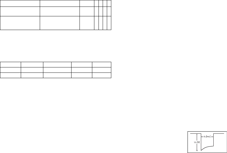
42
Gilt nur für Iforia 3
Technische Daten
Mechanische Kenndaten
Gehäuse
Implantate mit Anschlussblock DF-1/IS-1:
Materialien mit Kontakt zu Körpergewebe
•
Gehäuse: Titan
•
Anschlussblock: Epoxidharz
•
Blindstecker und Silikonstopfen: Silopren
Röntgenidentifikation
NT
Elektrische Kenndaten
Normen
Die Angaben erfolgen gemäß EN 45502-2-2:2008.
Messbedingungen
Soweit nicht anders angegeben, beziehen sich alle Angaben auf folgende Bedingungen:
•
Umgebungstemperatur: 37 ºC ± 2 °C
•
Stimulation/Wahrnehmung: 500 Ω ± 1 %
•
Schock: 50 Ω ± 1 %
Werksprogramm
•
Arrhythmiezonen VT1, VT2, VF: AUS
•
Antibradykardie-Stimulation: AUS
•
Home Monitoring: AUS
Angaben zur Telemetrie
•
Nominale Trägerfrequenz: 403,6 MHz
•
Maximale Sendeleistung: < 25 µW (-16 dBm)
Internationale Funkzulassung
Implantate mit BIOTRONIK Home Monitoring
®
sind mit einer Antenne für die drahtlose
Kommunikation ausgerüstet.
Angaben zur Telemetrie, Kanada, USA:
Dieses Gerät darf meteorologische Anlagen, Wetterdienst- und Erderkundungssatel-
liten, die im Frequenzbereich von 400,150 bis 406,000 MHz arbeiten, nicht stören, und
es muss jede Art von Störung akzeptieren, einschließlich der Störungen, die eine uner-
wünschte Betriebsweise hervorrufen können.
•
Dieses Implantat wird unter folgender Nummer bei Industry Canada registriert:
IC: 4708A-TACHNXT
Die Kennzeichnung IC vor der Zertifizierungs-/Registriernummer besagt nur, dass
die technischen Anforderungen von Industry Canada erfüllt sind.
•
Dieses Implantat wird unter folgender Nummer bei der Federal Communications
Commission registriert:
FCC ID: QRITACHNXT
Angaben zur Telemetrie, Japan:
Diesem Gerät wurde gemäß dem japanischen Gesetz über den Funkverkehr eine Iden-
tifikationsnummer entsprechend der "Verordnung betreffend die Zertifizierung der
Konformität zu technischen Vorschriften usw. von bestimmten Funkanlagen",
Artikel 2-1-8, zugewiesen.
•
R: 202-SMA026
Impulsform
Der Stimulationsimpuls hat folgende Form:
Die Impulsamplitude erreicht ihren maximalen Wert
am Anfang des Impulses (Ua). Mit zunehmender
Stimulationsdauer (tb) reduziert sich die Amplitude,
und zwar abhängig von der Stimulationsimpedanz.
Parameter Wertebereich Standard
VR
DX
DR
HF
Zyklendauer AUS; 30, 60, 90, 120,
180 Tage
30 Tage xxxx
Übertragung am: XX.XX.XXXX Nach-
sorge
+ 7 Tage
xxxx
Typ Anschluss B x H x T mm Volumen ccm Gewicht g
VR, DX, DR DF-1 65 x 55 x 11 31 80
HF DF-1 65 x 58,5 x 11 33 80
393467--B_GA_Iforia_ProMRI_mul-02.book Page 42 Friday, November 16, 2012 11:18 AM

de • Deutsch
43
Störfestigkeit
•
Hinweis zum Implantattyp DX Die EMV-Anforderungen werden erfüllt, solange für
die atriale Empfindlichkeit 1,0 mV (Werksprogramm) oder Werte ≥ 1,0 mV einge-
stellt werden. Bei Einstellung empfindlicherer Werte müssen Maßnahmen
ergriffen werden, um dennoch eine störungsfreie Therapie zu gewährleisten.
•
Hinweis zum Implantattyp HF: Bei unipolarer Wahrnehmung wird die Anforderung
für Störspannungen ≤ 0,3 mV (Spitze-Spitze) erfüllt.
Gleichtaktunterdrückung
ATP-Amplitude
Gemessen wurde ein Burst bei 500 Ω, einer Amplitude von 7,5 V (Toleranz ±1,5 V),
Impulsdauer von 1,5 ms, R-S1-Intervall von 300 ms und S1-Anzahl von 5:
Automatische Empfindlichkeitseinstellung
Messung der Ist-Werte, Wellenform des Testsignals: Standarddreieck. Beim
Implantattyp DX ist die programmierte atriale Empfindlichkeit um den Faktor 4 ver-
stärkt.
Schockenergie/Spitzenspannung
Bei Schockpfad: RV zu Gehäuse + SVC
Batteriedaten
Kenndaten der Batterietypen
Herstellerseitig werden folgende Daten angegeben:
Frequenz Gleichtaktunterdrückung
Atrium: DX* Atrium: DR, HF V rechts: VR, DR, HF V links: HF
16,6 Hz 58dB 53 dB 64 dB 66 dB
50 Hz 55 dB 55 dB 64 dB 66 dB
60 Hz 56 dB 56 dB 64 dB 68 dB
* nur Implantate mit DF-1/IS-1-Anschluss.
ATP-Amplitude Gemessenes
Minimum Gemessenes
Maximum Mittelwert
RV 7,67 V 7,67 V 5,00 V
LV 7,67 V 7,67 V 4,99 V
Empfindlichkeit Wert Toleranz Messwert
A: positiv 0,2 mV 0,2 ... 0,5 0,24 mV
A: negativ 0,24 mV
DX: A: positiv 0,2 mV 0,2 ... 0,52
(0,05 bis 0,13)
0,05 mV
DX: A: negativ 0,05 mV
RV: positiv 0,5 mV 0,3 ... 0,7 0,48 mV
RV: negativ 0,40 mV
LV: positiv 0,5 mV 0,3 ... 0,7 0,48 mV
LV: negativ 0,56 mV
Schockenergie
(Toleranz) Toleranz Spitzen-
spannung Messwert
Schockenergie Messwert
Spitzenspannung
1 J (0,7 ... 1,18) 90 ... 120 V 0,84 J 100 V
20 J (16,9 ... 20,9) 440 ... 480 V 18,1 J 469 V
40 J (33,8 ... 41,4) 620 ... 690 V 36,9 J 667 V
Hersteller GREATBATCH, INC.
Clarence, NY 14031 LITRONIK GmbH & Co
01796 Pirna,
Deutschland
Batterietyp GB 2992 LiS 3410 RA
Batteriekennung am
Programmiergerät
34
Implantattyp VR, (DX), DR, HF
Batteriespannung bei ERI 2,5 V 2,85 V
Ladezeit bei BOS 8 s 8 s
Ladezeit bei ERI 10 s 10 s
Nutzbare Kapazität bis ERI Iforia 3/5: 1390 mAh
Iforia 7: 1600 mAh
1390 mAh
Nutzbare Kapazität bis EOS 1730 mAh 1520 mAh
Empfindlichkeit Wert Toleranz Messwert
393467--B_GA_Iforia_ProMRI_mul-02.book Page 43 Friday, November 16, 2012 11:18 AM

44
Lagerdauer
Die Lagerdauer beeinflusst die Betriebszeit der Batterie.
•
Implantate sollen innerhalb von 19 Monaten zwischen Herstellungs- und Haltbar-
keitsdatum (Angabe auf der Verpackung) implantiert werden.
•
Wenn der ICD kurz vor dem Ende des Haltbarkeitsdatums implantiert wird, kann
sich die erwartete Betriebszeit um bis zu 16 Monate reduzieren.
Berechnung der Betriebszeiten
•
Die Betriebszeiten wurden wie folgt berechnet – je nach Implantattyp in allen
Kammern:
—
Impulsamplitude: 2,5 V
—
Impulsdauer: 0,4 ms
—
Stimulationsimpedanz: 500 Ω
—
Grundfrequenz: 60 bpm
—
Home Monitoring: EIN, täglich 1 Implantatnachricht und jährlich
12 Übertragungen eines IEGM-Online-HD
—
Diagnostikfunktionen und Aufzeichnungen: permanent eingestellt
•
Es werden 4 Kondensatorformierungen pro Jahr durchgeführt; deshalb müssen
mindestens 4 maximale Aufladungen für Schocks pro Jahr angenommen werden,
auch wenn weniger als 4 abgegeben werden.
Berechnung der Schockanzahl
Berechnung der maximalen Schockanzahl:
Lebensdauer [Jahre] * Schockanzahl/Jahr
Iforia 3/5 VR-T
Betriebszeiten mit Batterie GB 2992 oder LiS 3410 RA:
Iforia 5 VR-T DX
Betriebszeiten mit Batterie GB 2992 oder LiS 3410 RA:
Iforia 3/5 DR-T
Betriebszeiten mit Batterie GB 2992 oder LiS 3410 RA:
Stimulation Lebensdauer [Jahre] bei Schockanzahl/Jahr
48121620
0 %
10,42 8,39 7,01 6,03 5,28
15 %
10,14 8,20 6,89 5,93 5,21
50 %
9,55 7,81 6,60 5,72 5,05
100 %
8,81 7,31 6,24 5,45 4,83
Stimulation Lebensdauer [Jahre] bei Schockanzahl/Jahr
48121620
0 %
9,48 7,76 6,57 5,70 5,03
15 %
9,24 7,61 6,46 5,61 4,96
50 %
8,75 7,26 6,21 5,42 4,81
100 %
8,12 6,83 5,89 5,17 4,62
Stimulation Lebensdauer [Jahre] bei Schockanzahl/Jahr
48121620
0 %
9,48 7,76 6,57 5,70 5,03
15 %
9,02 7,45 6,35 5,53 4,89
50 %
8,10 6,81 5,88 5,17 4,61
100 %
7,08 6,07 5,32 4,73 4,26
393467--B_GA_Iforia_ProMRI_mul-02.book Page 44 Friday, November 16, 2012 11:18 AM

de • Deutsch
45
Iforia 3/5 HF-T
Betriebszeiten mit Batterie GB 2992 oder LiS 3410 RA:
Iforia 7 VR-T
Betriebszeiten mit Batterie GB 2992:
Iforia 7 VR-T DX
Betriebszeiten mit Batterie GB 2992:
Iforia 7 DR-T
Betriebszeiten mit Batterie GB 2992:
Iforia 7 HF-T
Betriebszeiten mit Batterie GB 2992:
Stimulation Lebensdauer [Jahre] bei Schockanzahl/Jahr
4 8 12 16 20
0 %
8,78 7,29 6,23 5,44 4,82
15 %
8,21 6,89 5,94 5,21 4,65
50 %
7,14 6,12 5,35 4,76 4,28
100 %
6,01 5,27 4,69 4,23 3,85
Stimulation Lebensdauer [Jahre] bei Schockanzahl/Jahr
4 8 12 16 20
0 %
11,78 9,52 7,98 6,87 6,03
15 %
11,48 9,32 7,84 6,76 5,95
50 %
10,81 8,87 7,52 6,53 5,76
100 %
9,99 8,31 7,11 6,21 5,52
Stimulation Lebensdauer [Jahre] bei Schockanzahl/Jahr
4 8 12 16 20
0 %
10,73 8,82 7,48 6,50 5,74
15 %
10,48 8,65 7,36 6,40 5,66
50 %
9,92 8,26 7,08 6,19 5,50
100 %
9,22 7,77 6,71 5,91 5,27
Stimulation Lebensdauer [Jahre] bei Schockanzahl/Jahr
4 8 121620
0 %
10,73 8,82 7,48 6,50 5,74
15 %
10,22 8,47 7,23 6,31 5,59
50 %
9,20 7,76 6,70 5,90 5,27
100 %
8,05 6,92 6,07 5,40 4,87
Stimulation Lebensdauer [Jahre] bei Schockanzahl/Jahr
4 8 121620
0 %
9,96 8,29 7,10 6,20 5,51
15 %
9,33 7,85 6,77 5,95 5,31
50 %
8,12 6,97 6,11 5,43 4,89
100 %
6,85 6,01 5,36 4,83 4,40
393467--B_GA_Iforia_ProMRI_mul-02.book Page 45 Friday, November 16, 2012 11:18 AM
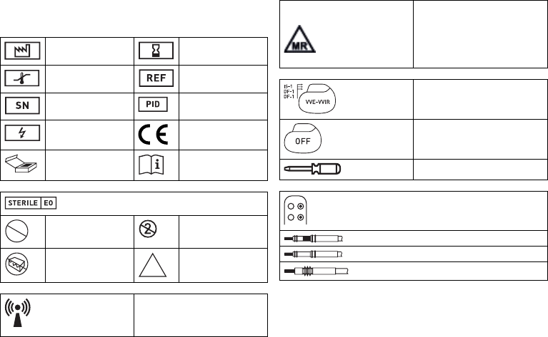
46
Legende zum Etikett
Etikett auf der Verpackung
Die Symbole auf dem Etikett bedeuten Folgendes:
Herstellungsdatum Verwendbar bis
Temperaturbegrenzung Bestellnummer
Seriennummer Produktidentifikations-
nummer
Gefährliche Spannungen CE-Zeichen
Inhalt Gebrauchsanweisung
beachten
Sterilisiert mit Ethylenoxid
Nicht resterilisieren Nicht wiederverwenden
Bei beschädigter Verpa-
ckung nicht verwenden
Unsteril
Sender mit nicht ionisierender elektro-
magnetischer Strahlung auf angegebener
Frequenz
STERILIZE
2
NON
STERILE
Symbol auf Etiketten von Implantaten mit
ProMRI
®
:
MR conditional: Patienten, die ein System
aus Implantaten tragen, deren Verpa-
ckungen mit diesem Symbol versehen
sind, können unter genau definierten
Bedingungen einer MRT-Untersuchung
unterzogen werden
Beispiel
Implantat: NBG-Code und kompatible
Elektroden
Beispiel
Werksprogramm Therapie: AUS
Schraubendreher
Beispiel für Anschlussblock DF-1/IS-1
Bipolarer IS-1-Stecker
Unipolarer IS-1-Stecker
Unipolarer DF-1-Stecker
393467--B_GA_Iforia_ProMRI_mul-02.book Page 46 Friday, November 16, 2012 11:18 AM