BIXOLON CM-MS300 WIFI Module User Manual manual
BIXOLON Co.,Ltd. WIFI Module manual
UserManual.wiki
>
BIXOLON
>
CM MS300 User Manual
manual
Navigation menu
Upload a User Manual
Namespaces
Wiki Guide
HTML
PDF
Info
Views
User Manual
Discussion / Help
Navigation
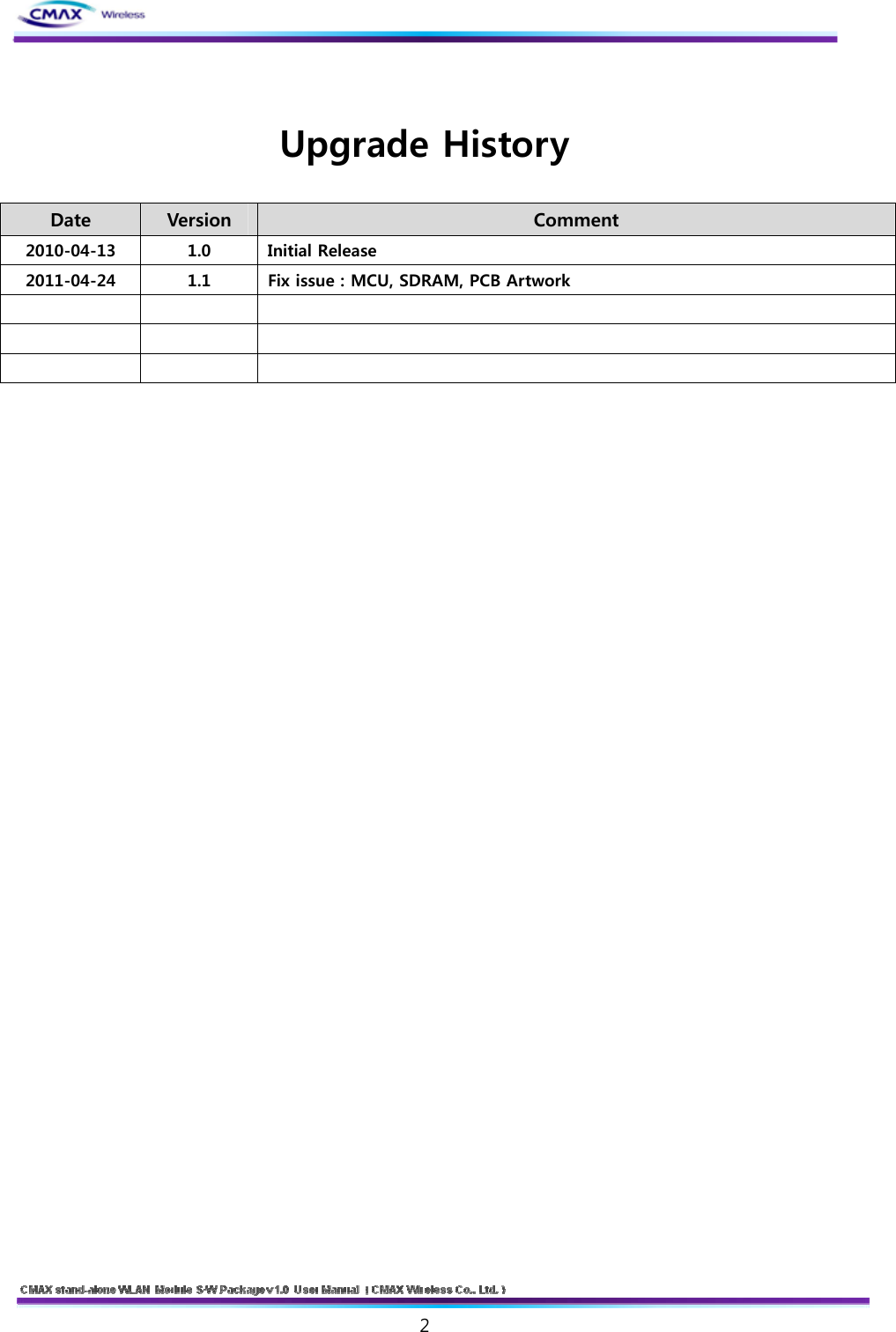
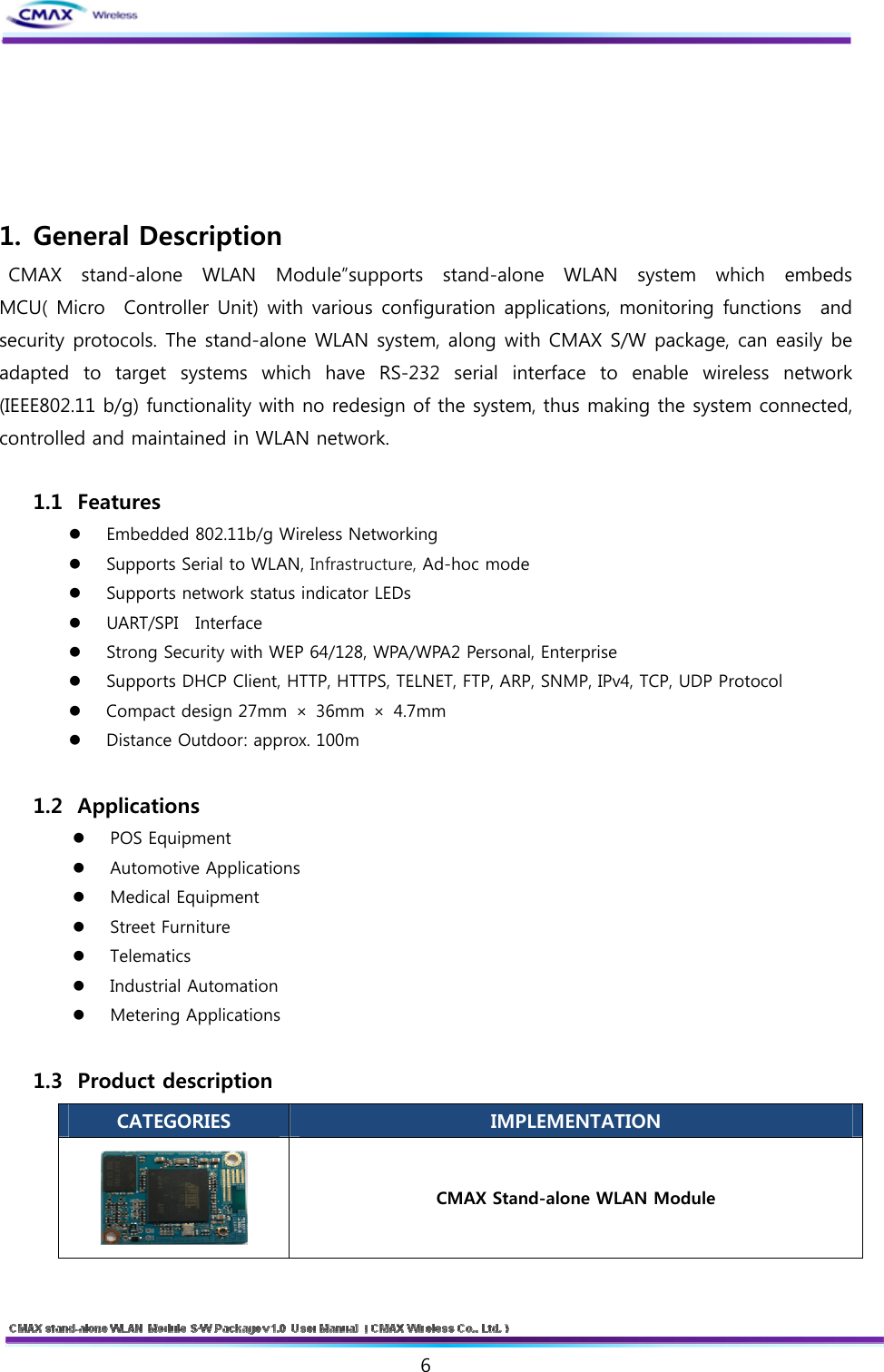
![7 Debugger board Serial Cable (Serial Communication Cable) Power (DC 5V/200mA Adapter) CD (User Manual and H/W, S/W Doc Package) [Table 1.3.1] Product Description 1.4 Specifications CATEGORIES FEATURE IMPLEMENTATION Wireless Standard IEEE802.11b, IEEE802.11g Frequency Range 2.412~2.462GHz Channels 1 ~ 11 channels 802.11b: max. 18dBm (@11Mbps) Max Transmit Power 802.11g: max. 15dBm (@54Mbps) 802.11b: min. -76dBm (@11Mbps) Receive Sensitivity 802.11g: min. -65dBm (@54Mbps) 802.11b : 1M ~ 11 Mbps (TBD) Data Rates 802.11g : 6M ~ 54 Mbps (TBD) Modulation Schemes 802.11b – BPSK, QPSK, CCK, DSSS 802.11g – BPSK, QPSK, 16-QAM, 64-QAM, OFDM Range Up to 100m free space (Outdoor) Wireless Specification Connection Modes Infrastructure and Ad-hoc (IBSS) Antenna Modes Antenna To support one chip antenna or external one antenna via connector Baud Rate 115,200bps Bits 8 Parity None Stop bits 1 UART Interface Flow Control CTS/RTS(hardware)](https://usermanual.wiki/BIXOLON/CM-MS300/User-Guide-1522082-Page-7.png)
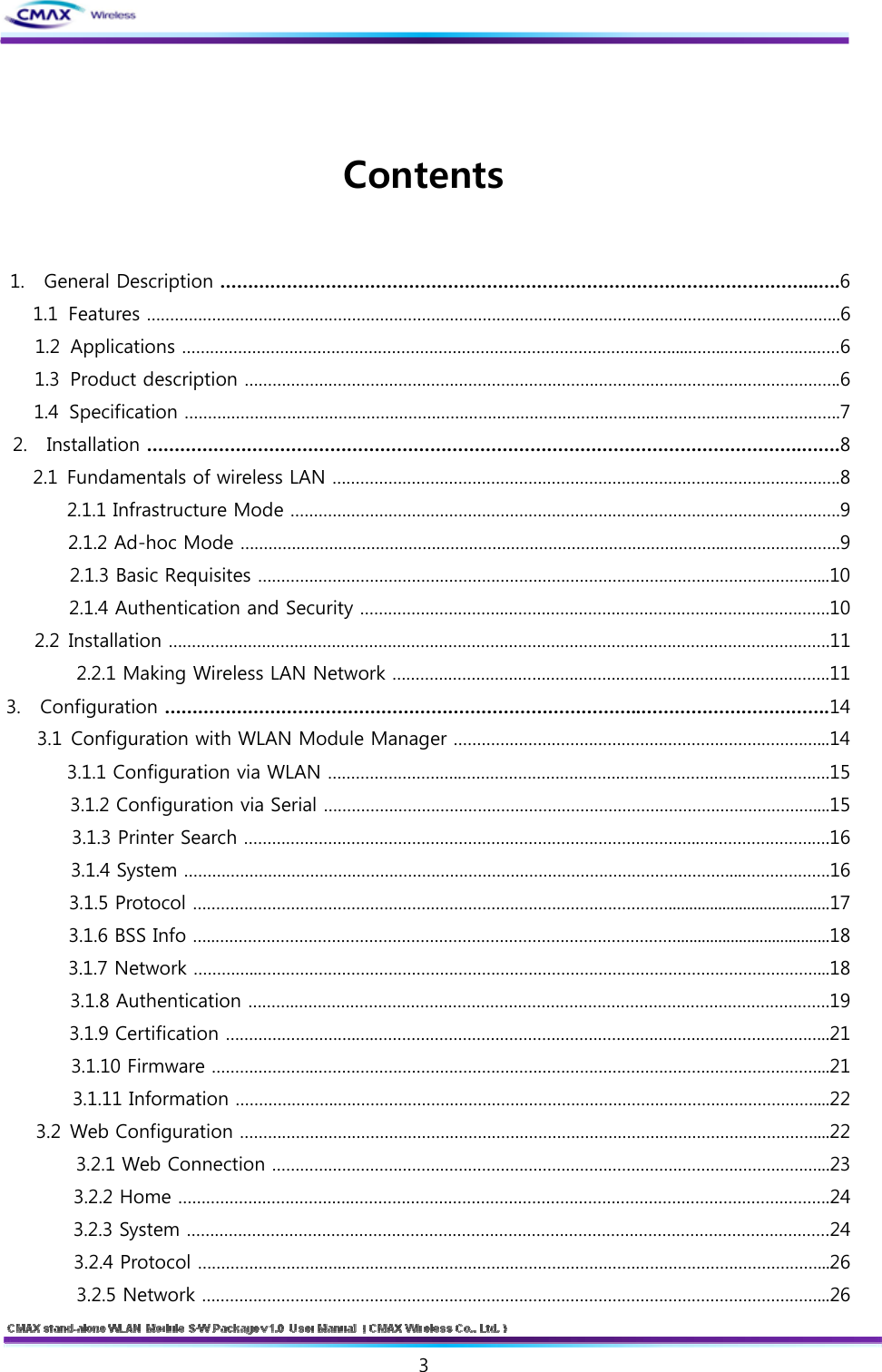
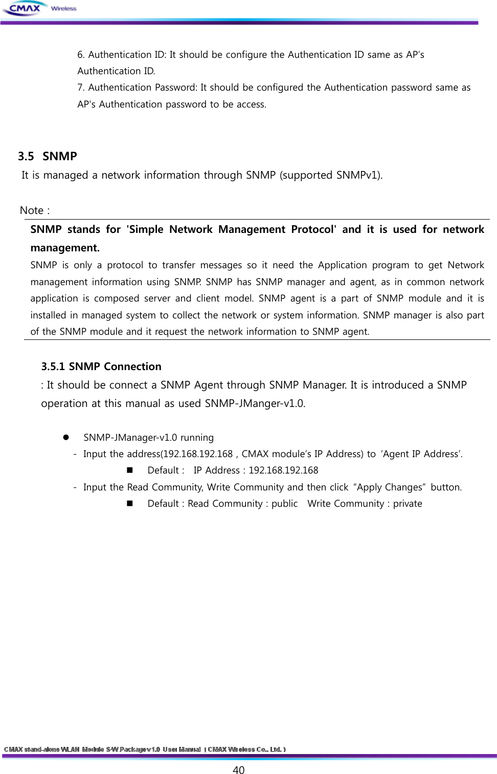
![8 SPI Interface Transfer Rate 10Mbps Open Connection Shared Key(WEP encryption 64 and 128 bit options) WPA-PSK, WPA2-PSK WPA1/2 Enterprise(EAP-TLS, EAP-TTLS, PEAP, LEAP, FAST) Security SSL2 / SSL3 / TLS1 Network Drivers 802.11b, 802.11g Protocol Internet DHCP Client, HTTP, HTTPS, TELNET, FTP, ARP, ICMP, SNMP, IPv4, TCP, UDP Power 85mA * 3.3V ( Peak 90mA * 3.3V) Power Consumption 280.5mW (Peak 297mW) MCU Specification 266MHz ARM9 with SRAM 32M and Flash 8M Upgradeability Upgradeability Firmware upgradeable via UART and Wireless LAN Operation Temperature -5℃ ~ 55℃ (TBD) Environmental Storage Temperature -20℃ ~ 70℃ (TBD) Operation: 10% to 90%, Non-Condensing Humidity Storage: 5% to 90%, Non-Condensing Dimensions 27mm × 36mm × 4.7mm Physical Weight 5g Operation Mode Infrastructure , Ad-hoc Operating System FreeRTOS Management WLAN Module Manager, HTTP, HTTPS, TELNET, FTP Development Kit Configuration Tools Development board and software tools Command Line Interface [Table 1.4.1] Specification 2. Installation 2.1 Fundamentals of wireless LAN CMAX Module supports IEEE802.11b/g. The IEEE802.11b and IEEE802.11g support 11Mbps and 54Mbps transmission rate respectively. There are two types of wireless LAN networks – infrastructure and ad-hoc.](https://usermanual.wiki/BIXOLON/CM-MS300/User-Guide-1522082-Page-8.png)
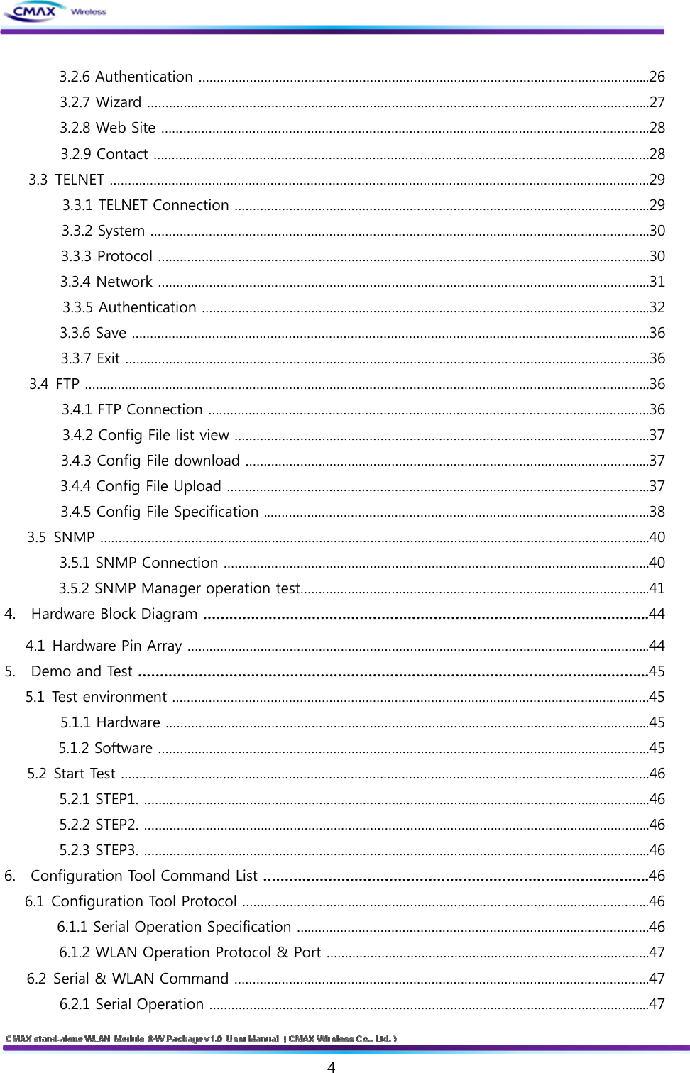
![9 [Figure 2.1.1] Reference Network Architecture 2.1.1 Infrastructure Mode The wireless LAN stations communicate through an Access Point (AP). So, at least one AP is needed to make the infrastructure network. The wireless LAN station can talk to wired network hosts because AP relays between wireless LAN stations as well as between wireless LAN station and wired LAN (Ethernet) host. [Figure 2.1.1.1] Infrastructure 2.1.2 Ad-hoc Mode Wireless stations communicate each other without the AP. So user can make a system more simply. It is proper if there’s no wired LAN requirement and it is a small network. Some people call it peer-to-peer mode.](https://usermanual.wiki/BIXOLON/CM-MS300/User-Guide-1522082-Page-9.png)
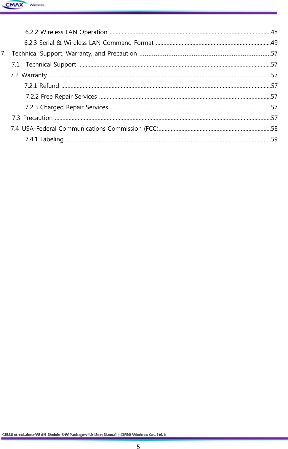
![10 [Figure 2.1.2.1] Ad-Hoc 2.1.3 Basic Requisites SSID It is an identifier to identify the particular wireless LAN. So the same SSID should be configured to all stations to communicate in the same wireless network. In case of infrastructure mode, user has to set his station’s SSID as same as AP’s. Channel IEEE802.11b/g wireless LAN stations communicate through the ISM (Industrial, Scientific, and Medical) band whose frequency is about 2.4GHz. IEEE802.11 specification divides this band into 14 channels every 5MHz. If user installs more than one wireless LAN networks in the same area, the channels should be apart more than 4 channels to avoid interferences. 2.1.4 Authentication and Security Authentication A wireless LAN station should get authentication from the AP in the infrastructure mode. There are the Open system and the Shared key for the authentication methods. WEP (Wired Equivalent Privacy) The WEP is a secure protocol for wireless LAN. There are two kinds of WEP method - 64 bits and 128 bits key. WPA (Wi-Fi Protected Access) WPA is a security standard for users of device equipped with Wi-Fi wireless connection. It is an improvement on and is expected to replace the original Wi-Fi security standard, Wired Equivalent Privacy (WEP). There are two modes about the user authentication in WPA security. The one is Enterprise which has authentication server and the other one is](https://usermanual.wiki/BIXOLON/CM-MS300/User-Guide-1522082-Page-10.png)
![11 PSK (Pre-Shared Key) which doesn’t have any server. CMAX Module supports both Enterprise mode and Personal mode (WPA-PSK). WPA 2 To final security of Wireless LAN, IEEE 802.11i, a standard about Wireless LAN, has suggested the Counter Mode with Cipher Block Changing Message Authentication Code Protocol (CCMP) for replacing the TKIP. CCMP uses Advanced Encryption Standard (AES), it is the WPA 2 that adopts the using the method. WPA 2 has also both Enterprise and PSK mode. CMAX Module supports also both them. 2.2 Installation Before testing, users should connect the CMAX Module. There are two methods for connecting. The first method is to connect a target device with the serial port and the other method is to connect by wireless LAN card on your PC. [Figure 2.2.1] Connect between CMAX Module and a PC 2.2.1 Making Wireless LAN Network Even though you connect an AP on your network, wireless LAN network could not be made automatically. You should configure values of items which related with wireless network. Please follow the below steps. Connect the CMAX Module through serial port Start the WLAN Module Manager on your PC. Push the “Connect” button after Selecting a COM port, User ID and User Password as the same values with the your COM port.](https://usermanual.wiki/BIXOLON/CM-MS300/User-Guide-1522082-Page-11.png)
![12 [Figure 2.2.1.1] Connect through serial port Connect the CMAX Module through WLAN Start the WLAN Module Manager on your PC. Click the “Connect” button after inserting IP Address, User ID and User Password as the same values with the CMAX Module. [Figure 2.2.1.2] Connect through WLAN Configuring Wireless LAN Parameters Move to the [Network] menu and setting SSID as the same values with the AP’s. Then, move to the [Authenticaton] menu and setting security options. Finaly, Click the “Update” button. Please ask the manufacturer of the AP, when you want to know about setting the AP’s value.](https://usermanual.wiki/BIXOLON/CM-MS300/User-Guide-1522082-Page-12.png)
![13 [Figure 2.2.1.3] Configuring Wireless LAN Parameters If you want to make an Ad-hoc network, choose the [Ad-hoc] as the value of [WLAN Topology] and set a value of [SSID]. Then, try to connect your PC to the network. 2.2.2 Setting Network Aera This step is for setting both CMAX Module and your PC to be located the same network. If only they are, the TCP connection between them can be established. Setting of the PC Add or change the IP address of the network adapter on your PC like following. Get into the menu of [Windows Control Panel] >> [Network Connections] >> [Properties of the Network Adapter - with right click of your mouse]. Then, you can show the properties of [Internet Protocol (TCP/IP). In there, press the [Advanced] button for adding an IP Address like the below figure. [Figure 2.2.2.1] adding / changing the IP address of users’ PC Setting of CMAX Module CMAX Module uses WLAN Module Manager as it’s a configuration program. WLAN Module Manager is for MS Windows, and this is comfortable to use because it doesn’t](https://usermanual.wiki/BIXOLON/CM-MS300/User-Guide-1522082-Page-13.png)
![14 need installation. First, search your WLAN Module via network. All the values of parameters are set the default values in the factory. To apply it to your system, proper values should be set via WLAN Module Manager. Major parameter’s default values are listed on below table. To implement this simple test, keep these values without any changes. DISTRIBUTION FUNCTION VALUE User ID admin System User Password password FTP Disable TELNET Disable HTTP Enable / HTTPS is disable Disable Community Name (Read) : Public Community Name (Write) : Private Trap Destination IP Address : 0.0.0.0 Trap Destination Community Name : Public Protocol SNMP Trap Mode : 1 (Enable), 0 (Disable) Locality Disable Network Mode Ad-hoc, channel 1 SSID CMAX_adhoc IP Assignment Method Manual Allocation IP : 192.168.192.168 Subnet : 255.255.255.0 Network IP, Subnet, Gateway Gateway : 192.168.192.1 Open System None Authentication Shared key None [Table 2.2.2.1] Default values of Major parameters 3 Configuration 3.1 Configuration with WLAN Module Manager](https://usermanual.wiki/BIXOLON/CM-MS300/User-Guide-1522082-Page-14.png)
![15 [Figure 3.1.1] initial appearance of WLAN Module 3.1.1 Configuration via WLAN Checklists Make sure the WLAN connection between your PC and WLAN Module Manager. If they are the same network, [search] button can be used. If they aren’t, [IP Address] should be inserted to use. Procedures 1) Printer Address : Set the values of the CMAX Module’s IP Address properly 2) User ID : Set the values of the User ID 3) User Password : Set the values of the Password 4) Connect : Connect through Wireless LAN to CMAX Module 5) Next : Move to System Configuration page. Note : If you want to save [ID/Password], it choose the checkbox. 3.1.2 Configuration via Serial Checklists Make sure the connection between your PC and WLAN Module Manager using RS232 direct cable. To use this, WLAN Module Manager has to be operating in the [Serial Configuration] mode. You press the “Connect” button after Selecting a COM port, User ID and User Password as the same values with the your COM port. Then, You can enter the [Serial Configuration] mode.](https://usermanual.wiki/BIXOLON/CM-MS300/User-Guide-1522082-Page-15.png)
![16 Procedures 1) Serial Port : Select a COM port as the same values with the your COM port. 2) User ID : Set the User ID 3) User Password : Set the User Password 4) Connect : Connect through Serial communication to CMAX Module 5) Next : Move to the configuration page of system Note : If you want to save [ID/Password], it choose the checkbox. After changing the configuration, you must be rebooted CMAX Module. 3.1.3 Printer Search : Provide information of CMAX Module in the network. [Figure 3.1.3.1] Printer Search Reset : Delete the printer information Search : Search active printers in the network. If a network problem occurs, the printers will not scan. Then, you press the [Search] button again. Select : After selecting a printer to connect, you should press [Select] button. 3.1.4 System : Set the Printer Name, Printer Port Num, User ID and User Password. User ID and password will be used to set the configuration.](https://usermanual.wiki/BIXOLON/CM-MS300/User-Guide-1522082-Page-16.png)
![17 [Figure 3.1.4.1] System Setting Printer Name : Set the [Printer Name] Print Port Num : Set the [Print Port Num] User ID : Set the [User ID] User Password : Set the [User Password] Confirm Password : Set correct values of [Confirm Password] Next : Move to the configuration page of protocol Back : Move to the configuration page of connection 3.1.5 Protocol : Select to use ftp, http and snmp that is application. For a description of each feature in the manual can be found at. [Figure 3.1.5.1] Protocol Setting](https://usermanual.wiki/BIXOLON/CM-MS300/User-Guide-1522082-Page-17.png)
![18 Task Sta te - Set the HTTPS, TELNET, FTP and SNMP that are applications if you use. SNMP - To perform SNMP sets for each item. Next : Move to the configuration page of BSS Information Back : Move to the configuration page of System 3.1.6 BSS Info : After Searching on AP(Access Point), user can select to connect at the AP. Then, AP’s SSID will be inserted automatically. [Figure 3.1.6.1] BSS Setting Reset : Delete current information of BSSID Get BSS Information : Scanning information of BSSID. If the problem of network occurs, the printers will not scan. Then, you press the [Get BSS Information] button again. Select : Select BSS that searched. Next : Move to the configuration page of Network Back : Move to the configuration page of Protocol 3.1.7 Network : Set the network parameter of CMAX Module](https://usermanual.wiki/BIXOLON/CM-MS300/User-Guide-1522082-Page-18.png)
![19 [Figure 3.1.7.1] Network Setting Network Mode : Select the Infra Network or Adhoc mode. Note : If adhoc mode user selects to connect a adhoc-channel (1~14). SSID : Set the SSID that user is going to connect. SSID Can set up maximum of 32 bytes. Inactivity Time : After connecting to the server of printer, It is time to maintain a connection with the server. Default setting : Disable, Maximun time : 32767(sec) IP Assignment Method : Supported Automatic Allocation(DHCP Client) or Manual Allocation. Default setting : Manual Allocation - Automatic Allocation(DHCP Client) : Assigns the IP Address that is assigned in the DHCP server automatically - Manual Allocation : Does not assign the IP address in the AP(Access Poing)’s DHCP server. User should insert the IP Address that is such as IP Address of AP. IP Address : Insert the [IP Address] of AP : Default IP Address : 192.168.192.168 Subnet Mask : Insert the [Subnet Mask] of AP : Default subnet Mask : 255.255.255.0 Gateway : Insert the [Gateway] of AP : Default Gateway : 192.168.192.1 Next : Move to the configuration page of Authentication Back : Move to the configuration page of BSS Information 3.1.8 Authentication : Set a security configuration of the CMAX Module](https://usermanual.wiki/BIXOLON/CM-MS300/User-Guide-1522082-Page-19.png)
![20 [Figure 3.1.8.1] Authentication Setting Authentication : It is security configuration between CMAX Module and AP(Access Point) FIELD DESCRIPTION Cryptograph It should be select NONE or WEP64/128 as the setting of AP to be access Open System WEP Key You can input the max 26charater,. It Configure to WEPB64/18 if you input it like the following format. - WEP64 (5 ASCII, 10 HEX), WEP128 (13 ASCII, 26 HEX) Cryptograph Select a WEP64/128 same AP’s configuration to be access. Shared Key WEP Key You can input the max 26charater,. It Configure to WEPB64/18 if you input it like the following format. - WEP64 (5 ASCII, 10 HEX), WEP128 (13 ASCII, 26 HEX) Cryptograph You should same to configure a TKIP/AES with AP to be access. WPA-PSK / WPA2-PSK PSK Key You should same to input a TKIP/AES with AP to be access. Cryptograph You should same to configure a cryptograph with AP to be access.EAP You should same to configure a EAP Mode with AP to be access. ID You should Input the ID with configured certificate Server WPA-TKIP / WPA2-AES Password You should Input the Password with configured certificate Server However, If EAP Configuration is a EAP-TLS, you should input the private_key_password that is certificate password that generated for CMAX module. [Table 3.1.8.1] Security setting Save : It is function to Save the configuration information that you have set Saved file can set through uploading with FTP Update : User will save the configuration information to CMAX Module Back : Move to the configuration page of Network Note : To upload a file must be named “Config” should be](https://usermanual.wiki/BIXOLON/CM-MS300/User-Guide-1522082-Page-20.png)
![21 3.1.9 Certification : Can upload Certificates to CMAX Module for EAP-TLS certification [Figure 3.1.9.1] Upload Certificate Upload Certification - Open file : Select the Certificate - Update : Save the Selecting a certificate to CMAX Module 3.1.10 Firmware : It has been supporting the firmware upgrade. If It does not connect from CMAX Module, can not update the firmware. To stable firmware upgrade, we are not supported doing all of the eatures. After updating the firmware, CMAX Module must be rebooted. [Figure 3.1.10.1] Upgrade Firmware](https://usermanual.wiki/BIXOLON/CM-MS300/User-Guide-1522082-Page-21.png)
![22 Open file : Select a firmware type of [WLAN_M*.Bin] Update : Update a firmware to CMAX Module Stop : Stop the firmware upgraded Note : Emergency mode : If an error occurs while firmware upgrade, CMAX module will be started to the emergency mode. Emergency mode does not support the security features. So You must update the full firmware to operate normal mode. 3.1.11 Information : Product and firmware information is displayed [Figure 3.1.11.1] Information Product Information : Product name Firmware Version : Firmware version Update Date : Updated date Mac Address : CMAX Module’s Mac Address 3.2 Web Configuration Set the CMAX Modules’s configuration through web connecting](https://usermanual.wiki/BIXOLON/CM-MS300/User-Guide-1522082-Page-22.png)
![23 3.2.1 Web Connection : CMAX Module can Set configuration using the HTTP, HTTPS protocol. HTTP and HTTPS settings are same. Only, HTTPS secure connection is supported. Default setting is HTTP HTTP Connection : Start internet explorer through “http://192.168.192.168” Default : ID : admin Password : password [Figure 3.2.1.1] Sign in with your HTTPS Connection : Start internet explorer through https://192.168.192.168 Default : ID : admin Password : password Note : When establishing a HTTP connection, to continue to ignore security warnings. [Figure 3.2.1.2] HTTPS Sign in with your](https://usermanual.wiki/BIXOLON/CM-MS300/User-Guide-1522082-Page-23.png)
![24 Note : Web Server Security feature - Supported the SSL 2.0, SSL 3.0 and TLS 1.0 - For HTTPS connections, if you want to access from the computer, security protocol should be checked. 3.2.2 Home : Display the system, protocol and network information in the CMAX Module [Figure 3.2.2.1] Home 3.2.3 System : After inserting the [Pinter Name], [Printer Port], [User Name] and [User Password], user should press the “SUBMIT” button to set system configuration [Figure 3.2.3.1] System Setting](https://usermanual.wiki/BIXOLON/CM-MS300/User-Guide-1522082-Page-24.png)
![25 Printer Name : Set the [Printer Name] Print Port Num : Set the [Print Port Number] User ID : Set the [User ID] User Password : Set the [User Password] Confirm Password : Set correct values of [Confirm Password] Default : User ID : admin , User Password : password 3.2.4 Protocol : Set the HTTPS, TELNET, FTP and SNMP that are applications if you use. Then To perform SNMP sets for each item. After inserting, user should press the “SUBMIT” button to set Protocol configuration [Figure 3.2.4.1] Protocol Setting Setup - HTTPS (Default setting is HTTP) - TELNET (Default setting is disable) - FTP (Default is disable) - SNMP (Default is disable) SNMP - Community Name (Read) : Read Community Default : Public - Community Name (Write) : Write Community Default : Private - Trap IP Address : Trap IP Address. Default : 0.0.0.0 - Trap Community : Trap Community Default : Public](https://usermanual.wiki/BIXOLON/CM-MS300/User-Guide-1522082-Page-25.png)
![26 3.2.5 Network : After inserting the network configuration, user should press the “SUBMIT” button to set. [Figure 3.2.5.1] Network Setting Network Mode : Select the Infra Network or Adhoc mode. Note : If adhoc mode user selects to connect a adhoc-channel (1~14). SSID : Set the SSID that user is going to connect. SSID Can set up maximum of 32 bytes. Inactivity Time : After connecting to the server of printer, It is time to maintain a connection with the server. Default setting : Disable, Maximun time : 32767(sec) IP Assignment Method : Supported Automatic Allocation(DHCP Client) or Manual Allocation. Default setting : Manual Allocation Automatic Allocation(DHCP Client) : Assigns the IP Address that is assigned in the DHCP server automatically Manual Allocation : Does not assign the IP address in the AP(Access Poing)’s DHCP server. User should insert the IP Address that is such as IP Address of AP. IP Address : Insert the [IP Address] of AP : Default IP Address : 192.168.192.168 Subnet Mask : Insert the [Subnet Mask] of AP : Default subnet Mask : 255.255.255.0 Gateway : Insert the [Gateway] of AP : Default Gateway : 192.168.192.1 3.2.6 Authentication : After inserting the security features, user should press the “SUBMIT” button to apply on the system.](https://usermanual.wiki/BIXOLON/CM-MS300/User-Guide-1522082-Page-26.png)
![27 [Figure 3.2.6.1] Authentication Setting Authentication : It is security configuration between CMAX Module and AP(Access Point) FIELD DESCRIPTION Cryptograph It should be select NONE or WEP64/128 as the setting of AP to be access Open System WEP Key You can input the max 26charater,. It Configure to WEPB64/18 if you input it like the following format. - WEP64 (5 ASCII, 10 HEX), WEP128 (13 ASCII, 26 HEX) Cryptograph Select a WEP64/128 same AP’s configuration to be access. Shared Key WEP Key You can input the max 26charater,. It Configure to WEPB64/18 if you input it like the following format. - WEP64 (5 ASCII, 10 HEX), WEP128 (13 ASCII, 26 HEX) Cryptograph You should same to configure a TKIP/AES with AP to be access. WPA-PSK / WPA2-PSK PSK Key You should same to input a TKIP/AES with AP to be access. Cryptograph You should same to configure a cryptograph with AP to be access.EAP You should same to configure a EAP Mode with AP to be access. ID You should Input the ID with configured certificate Server WPA-TKIP / WPA2-AES Password You should Input the Password with configured certificate ServerHowever, If EAP Configuration is a EAP-TLS, you should input the private_key_password that is certificate password that generated for CMAX module. [Table 3.2.6.1] Security setting 3.2.7 Wizard : Provides that user can easily insert the configuration of system. After inserting the configurations, user should press the “NEXT” button to apply on the system.](https://usermanual.wiki/BIXOLON/CM-MS300/User-Guide-1522082-Page-27.png)
![28 [Figure 3.2.7.1] Wizard start page [Figure 3.2.7.2] Wizard result page 3.2.8 Web Site : Move to the website of CMAX Wireless 3.2.9 Contact : User will be connected Customer Service by the E-Mail.](https://usermanual.wiki/BIXOLON/CM-MS300/User-Guide-1522082-Page-28.png)
![29 3.3 TELNET You can configure the CMAX module by TELNET Note : TELNET : TELNET is Text-based remote access service and based TCP/IP Protocol. CMAX module configuration : Input the number provided on the left side of the menu and then enter the "Enter" to enter the next entry. Menu move example Menu number : move to next menu. $ : go to the previous menu. # : Go to the main menu. 3.3.1 TELNET Connection : Connect by Telnet Client.( Microsoft Windows xp based on the description.) Windows command execution. - Windows’s Beginning – Run – input “command”. Input “TELNET 192.168.192.168(IP Address of CMAX module)” to command windows. Default : IP Address : 192.168.192.168 [Figure 3.3.1.1] TELNET Configuration Server Connection Screen - Input “User ID, User Password” and then enter the “Enter” Default : User ID : admin User Password : password [Figure 3.3.1.2] TELNET Configuration major menu [1] System: Configure System information. [2] Protocol: You can select to Enable(1) or disable(0) the application of the activities. And configure SNMP access information. (Default setting HTTP) [2] Protocol: You can select to Enable(1) or disable(0) the application of the activities. And configure SNMP access information. (Default setting HTTP) Network: Configure Network parameter of CMAX module.](https://usermanual.wiki/BIXOLON/CM-MS300/User-Guide-1522082-Page-29.png)
![30 Authentication: Configure security parameter of CMAX module. Save: You can store the configuration information that input so far to the CMAX module Exit : Terminate TELNET connection. 3.3.2 System : You can configure Printer Name, Print Port Number, ID and User Password. User ID and User Password is applied to all application of CMAX module. Select “[1]System” to “configuration main menu”. [Figure 3.3.2.1] TELNET System information menu [0] System Name : Configure CMAX Module name [1] TCP Server Port Num: Configure TCP Server port number. [2] User ID: Configure user ID. [3] User Password : Configure user password. [$] Back: Go to the previous menu. [#] Main Menu : Go to the main menu. 3.3.3 Protocol : You can select to enable or disable the application(HTTP, HTTPS, TELNET, FTP, SNMP) of the use and configure SNMP Parameter(Community, Trap IP Address, Trap Community). Select [2]Protocol to “Configuration main menu.” [Figure 3.3.3.1] TELNET Protocol menu](https://usermanual.wiki/BIXOLON/CM-MS300/User-Guide-1522082-Page-30.png)
![31 [Figure 3.3.3.2] TELNET Task State Protocol menu Select “[0]Task State” to “Protocol menu.” [0] HTTPS : Configure to Enable(1) or Disable(0) to HTTPS. ( default HTTP ) [1] TELNET : Configure to Enable(1)/Disable(0) to TELNET. [2] FTP : Configure to Enable(1)/Disable(0) to FTP [3] SNMP : Configure to Enable(1)/Disable(0) to SNMP. [Figure 3.3.3.3] TELNET SNMP Connection Information menu Select “[1] SNMP” to Protocol menu. [0] Community Name (Read) :If SNMP is Enable(1) state, you can configure to accessed community of read mode.. [1] Community Name (Write) : If SNMP is Enable(1) state, you can configure to accessed community of write mode. [2] Trap IP Address : If SNMP is Enable(1) state, you can configure to IP Address that received Trap message. [3] Trap Community : If SNMP is Enable(1) state, you can configure to Trap community. [$] Back: Go to the previous menu. [#] Main Menu : Go to the main menu. 3.3.4 Network : Configure Network parameter of CMAX module. Select “[3] Neteork” to Configuration main menu.](https://usermanual.wiki/BIXOLON/CM-MS300/User-Guide-1522082-Page-31.png)
![32 [Figure 3.3.4.1] TELNET Network menu [0] Network Mode : Select a network mode( Infra Network(0) / Adhoc(1)). [1] Adhoc Channel : Configure Adhoc Channel(1~14) to Connection. [2] SSID : It should be configured the SSID same as AP's SSID to be access. [3] Inactivity Time : It means a time limit keeping connection that without data communication between client and server. [4] IP Assignment Method : Select IP Assignment megthod( DHCP(0)/Manual Alloccation(1) ). [5] IP Address : If you selected Manual Alloccation(1), configure IP Address. [6] Subnet Mask : If you selected Manual Alloccation(1), configure Subnet Mask. [7] Gateway : If you selected Manual Alloccation(1), configure Gateway. [$] Back: Go to the previous menu. [#] Main Menu : Go to the main menu. 3.3.5 Authentication : Configure CMAX Module Security. It should be configured the Security same as AP's Security to be access. Select “[4]Authentication” to “configuration main menu”. [Figure 3.3.5.1] TELNET Security main menu [0] Authentication : You configure a security method.. Reference [Table 3.3.5.1] [1] Cyrptograph : Configure an encryption method according to security methods. [2] Key : Configure a key of WEP or PSK. [3] EAP : Configure an EAP Mode according to WPA/WPA2](https://usermanual.wiki/BIXOLON/CM-MS300/User-Guide-1522082-Page-32.png)
![33 [$] Back: Go to the previous menu. [#] Main Menu : Go to the main menu. [Figure 3.3.5.2] TELNET Open System Security main menu [0~5] Authentication : Configure a Security Mode. Reference [Table 3.3.5.1] [$] Back: Go to the previous menu. [#] Main Menu : Go to the main menu. “Authentication" is a function that CMAX module does authenticate to AP through to wireless FIELD DESCRIPTION Cryptograph It should be select NONE or WEP64/128 as the setting of AP to be access Open System WEP Key You can input the max 26charater,. It Configure to WEPB64/18 if you input it like the following format. - WEP64 (5 ASCII, 10 HEX), WEP128 (13 ASCII, 26 HEX) Cryptograph Select a WEP64/128 same AP’s configuration to be access. Shared Key WEP Key You can input the max 26charater,. It Configure to WEPB64/18 if you input it like the following format. - WEP64 (5 ASCII, 10 HEX), WEP128 (13 ASCII, 26 HEX) Cryptograph You should same to configure a TKIP/AES with AP to be access. WPA-PSK / WPA2-PSK PSK Key You should same to input a TKIP/AES with AP to be access. Cryptograph You should same to configure a cryptograph with AP to be access.EAP You should same to configure a EAP Mode with AP to be access. ID You should Input the ID with configured certificate Server WPA-TKIP / WPA2-AES Password You should Input the Password with configured certificate ServerHowever, If EAP Configuration is a EAP-TLS, you should input the private_key_password that is certificate password that generated for CMAX module. [Table 3.3.5.1] Security setting](https://usermanual.wiki/BIXOLON/CM-MS300/User-Guide-1522082-Page-33.png)
![34 [Figure 3.3.5.3] TELNET Open System Cryptograph menu [0] Open System : You should select ‘NONE[0]’ or ‘WEP64/128[1]’ [$] Back: Go to the previous menu. [#] Main Menu : Go to the main menu. [Figure 3.3.5.4] TELNET Shared Key Cryptograph menu [1] Shared Key : You should select ‘WEP64’ or ‘WEP128’ [$] Back: Go to the previous menu. [#] Main Menu : Go to the main menu. [Figure 3.3.5.5]TELNET WPA-PSK/WPA2-PSK a detailed menu. [0] Authentication : you should configure a authentication mode. Reference [Table 3.3.5.1] [1] Cyrptograph : You should configure a Cryptograph mode according to authentication mode [2] Key : You should a WEP key of PSK Key. [3] EAP : You should configure a EAP Mode according to WAP/WAP2 [$] Back: Go to the previous menu. [#] Main Menu : Go to the main menu.](https://usermanual.wiki/BIXOLON/CM-MS300/User-Guide-1522082-Page-34.png)
![35 [Figure 3.3.5.6] TELNET WPA-PSK/WPA2-PSK Cryptograph menu [2] WPA-PSK : You should select a ‘TKIP[0]’ or ‘AES[1]’ [3] WPA2-PSK : You should select a ‘TKIP[0]’ or ‘AES[1]’ [$] Back: Go to the previous menu. [#] Main Menu : Go to the main menu. [Figure 3.3.5.7]TELNET WPA/WPA2 a detailed menu. [0] Authentication : You should configure a authentication method. Reference [Table 3.3.5.1] [1] Cyrptograph : Configure an encryption method according to security methods. [2] Key : Configure a key of WEP or PSK. [3] EAP : Configure an EAP Mode according to WPA/WPA2 [$] Back: Go to the previous menu. [#] Main Menu : Go to the main menu. [Figure 3.3.5.8 ]TELNET WPA/WPA2 Cryptograph menu Cryptograph : It should be configured a cryptograph method with ‘TKIP[0]’ or ‘AES[1]’ [$] Back: Go to the previous menu. [#] Main Menu : Go to the main menu.](https://usermanual.wiki/BIXOLON/CM-MS300/User-Guide-1522082-Page-35.png)
![36 [Figure 3.3.5.9] TELNET EAP Configuration Menu. [0] EAP Mode: It should be selected same as AP’s EAP mode [1] EAP ID/PASSWORD: it should be configured same as AP’s EAP ID and password. [$] Back: Go to the previous menu. [#] Main Menu : Go to the main menu. 3.3.6 Save : To save a changed configuration information on CMAX module, select the ‘[5]Save’ in the configuration main menu. 3.3.7 Exit : To terminate a TELNET connection, select the ‘[6] Exit’ in the configuration main menu. 3.4 FTP It is function to Upload or Download 'Config file' for CMAX module configuration by FTP. If you modify the 'Config file' and upload that, it will be changed CMAX module setup. Note : FTP : File Transfer Protocol (FTP) is a standard network protocol used to exchange and manipulate files over a TCP/IP-based network(between server and client). Supported FTP command ls : List contents of remote directory Get: : Receive config file Put : Send config file CAUTION : To Upload a file, don’t use file-extension and use “config” to filename. 3.4.1 FTP Connection : It should be executed to Microsoft Windows xp Command line. Execute Windows command - Microsoft Windows xp’s beginning – run – input ‘command’ - It should be input command ‘FTP 192.168.192.168 (CMAX module’s IP Address)’ Default : IP Address : 192.168.192.168](https://usermanual.wiki/BIXOLON/CM-MS300/User-Guide-1522082-Page-36.png)
![37 [Figure 3.4.1.1] FTP Connection Screen - User ID, User Password 를 입력 후 “Enter”를 칩니다. - It should be input User ID and User password. Default : User ID : admin User Password : password 3.4.2 Config File list view : It should be confirmed a file as you input ‘ls’. [Figure 3.4.2.1] FTP ‘ls’ command executed screen 3.4.3 Config File download :It should be downloaded a file as you input ‘get config’. [Figure 3.4.3.1] FTP ‘get config’ command screen 3.4.4 Config File Upload : It should be uploaded a file as you input ‘put config’. you must use file name as ‘config’. [Figure 3.4.4.1] FTP ‘put config’ command screen](https://usermanual.wiki/BIXOLON/CM-MS300/User-Guide-1522082-Page-37.png)
![38 3.4.5 Config File Specification : Table 3.4.5.1 is downloaded file’s content from CMAX module by ‘get config’ command. To change a configuration value, input without blank in ‘bracket’([ ]). ** Caution!!! ** Do not change the order or contents of the menu. ** Only need to change the settings, please. [1] System 1. Printer Name: [unknown] 2. Printer Port Num: [9100] 3. User ID: [admin] 4. User Password: [password] [2] Protocol 1. Task State 1) HTTPS: [0] 2) TELNET: [0] 3) FTP: [0] 4) SNMP: [0] 2. SNMP 1) Community Name (Read): [public] 2) Community Name (Write): [private] 3) Trap IP Address: [0.0.0.0] 4) Trap Community: [public] [3] Network 1. Network Mode 1) Infra Network(0) / Adhoc(1): [1] 2) Adhoc Channel: [1] 2. SSID: [CMAX_adhoc] 3. Inactivity Time: [0] 4. IP Assignment Method: [1] 5. IP Address: [192.168.192.168] 6. SubnetMask: [255.255.255.0] 7. Gateway: [192.168.192.1] [4] Authentication 1. Authentication: [0] 2. Cryptograph: [0] 3. EAP Mode: [0] 4. WEP Key: [] 5. PSK Key: [] 6. Authentification ID: [] 7. Authentification Password: [] [Table 3.4.5.1] FTP ‘config’ file’s content](https://usermanual.wiki/BIXOLON/CM-MS300/User-Guide-1522082-Page-38.png)
![39 Describes in detail how the file should be configure. [1] System: Configure the system information. 1. Printer Name: Configure the system name. 2. Printer Port Num: Configure the TCP server port. 3. User ID: Configure the user ID. 4. User Password: Configure the user password. [2] Protocol: Configure the Application (HTTPS, TELNET, FTP, SNMP) as Enable(1) or Disable(0). And configure the SNMP connect information. 1. Task State 1) HTTPS: Configure the HTTPS as Enable(1) or Disable(0).(default configuration is HTTP) 2) TELNET: Configure the TELNET as Enable(1) as Disable(0). 3) FTP: Configure the FTP as Enable(1) as Disable(0). 4) SNMP: Configure the SNMP as Enable(1) or Disable(0). 2. SNMP 1) Community Name (Read): Configure the Read mode community.. 2) Community Name (Write): Configure the Write mode community. 3) Trap IP Address: If SNMP’s state is Enable(1), Configure the IP address for Trap message received. 4) Trap Community: If SNMP’s state is Enable(1), Configure the Trap community. [3] Network: Configure the CMAX module’s Network parameter. 1. Network Mode 1) Infra network(0) / Adhoc(1) : Select a network mode to connect 2) Adhoc Channel: If you selected Adhoc, you select channel(1~11) . 2. SSID: CMAX_adhoc: It should be input SSID as the setting of AP to be access 3. Inactivity Time: It should be configured a time limit keeping connection that without data communication between client and server. 4. IP Assignment Method: Select DHCP(0) or Manual Alloccation(1) 5. IP Address: If you selected Manual Alloccation(1), you configure a IP Address. 6. SubnetMask: If you selected Manual Alloccation(1), you configure a Subnet Mask. 7. Gateway: If you selected Manual Alloccation(1), you configure a Gateway. [4] Authentication: It should be configured the Security same as AP's Security to be access. 1. Authentication: Open System(0), Shared Key(1), WPA-PSK(2), WPA-PSK2(3), WPA(4), WPA2(5) 2. Cryptograph: NONE(0), WEP64/128(1), TKIP(2), AES(3) 3. EAP Mode: EAP-PEAP(0), EAP-TTLS(1), EAP-TLS(2), EAP-LEAP(3) 4. WEP Key: It should be configure the WEB key same as AP’s WEP key. 5. PSK Key: It should be configure the PSK key same as AP’s PSK key.](https://usermanual.wiki/BIXOLON/CM-MS300/User-Guide-1522082-Page-39.png)
![41 [Figure 3.5.1.1] SNMP Connection configuration screen 3.5.2 SNMP Manager operation test: it is description of basic SNMP operation. If you selected terminal node to ‘Get Tree’, get this value(client note value). [Figure 3.5.2.1] SNMP ‘get’ message operation screen](https://usermanual.wiki/BIXOLON/CM-MS300/User-Guide-1522082-Page-41.png)
![42 Get Next : You can bring the value at trees as selected a terminal node. [Figure 3.5.2.2] SNMP ‘getnext’ message opration screen You can configure the terminal node value to ‘set tree’. (You can set only the contents had set on "Write") [Figure 3.5.2.3] SNMP ‘set’ message operation screen](https://usermanual.wiki/BIXOLON/CM-MS300/User-Guide-1522082-Page-42.png)
![43 Walk: It can get the all item that terminal node of tree or terminal node of node. [Figure 3.5.2.4] SNMP ‘walk’ message operation screen Traps: If a specific event occurs, relevant(in the event) message is transmitted to trap address. - ColdStart: when a terminal rebooting works, coldstart message is transmitted to trap address. [Figure 3.5.2.5] SNMP coldStart message received screen - AuthenticationFailure: If ‘Read’, ‘Write’ Community is not correct, AuthenticationFailure message is transmitted to trap address.](https://usermanual.wiki/BIXOLON/CM-MS300/User-Guide-1522082-Page-43.png)
![44 [Figure 3.5.2.6] SNMP AuthenticationFailure message received screen 4. Hardware Block Diagram [Figure 4.1] Hardware Block Diagram 4.1 Hardware Pin Array](https://usermanual.wiki/BIXOLON/CM-MS300/User-Guide-1522082-Page-44.png)
![45 NUM NAME IN/OUT DESCRIPTION 1 VCC 3.3V Power 2 VCC 3.3V Power 3 VCC 3.3V Power 4 VCC 3.3V Power 5 WLAN_ID OUT WLAN Module ID 6 DDM IN/OUT Debug USB DDM 7 DDP IN/OUT Debug USB DDP 8 NRST IN H/W RESET 9 RXD IN UART RXD 10 EXT_WLAN_RST IN Factory Reset 11 RTS OUT UART RTS 12 TXD OUT UART TXD 13 Test Point1 IN/OUT Test Point In/Out 1 14 CTS IN UART CTS 15 LED_BLUE OUT BLUE LED Control GPIO 16 GPIO1 IN/OUT General Purpose In/Out 1 17 LED_RED OUT RED LED Control GPIO 18 DRxD IN Debug UART RXD 19 DTxD OUT Debug UART TXD 20 GND GROUND 21 GND GROUND 22 GND GROUND 23 GND GROUND 24 GND GROUND [Table 4.1.1] Hardware Pin Arry 5. Demo and Test This chapter explains several examples that it can be used for functional testing of CMAX module. Test environment is as follows. 5.1 Test environment 5.1.1 Hardware RS232 serial port with a PC CMAX module & CMAX test board PC's COM port and CMAX for the module's serial port to connect the serial cable is required. 5.1.2 Software](https://usermanual.wiki/BIXOLON/CM-MS300/User-Guide-1522082-Page-45.png)
![46 Configuration Tool of CMAX module Hyper Terminal( or other Terminal program) 5.2 Start Test 5.2.1 STEP1. It should be connect to CMAX Test board and PC’s Serial port. It should be turn on the CMAX test board. It should be connected the PC to CMAX module through serial interface. It should be run a Terminal program of PC by connected Serial(ex, HyperTerminal) 5.2.2 STEP2. (Wireless Configuration to between CMAX module and PC). It should be connected the PC to CMAX module through wireless LAN. It should be configured the PC’s Network to next value. IP( 192.168.192.XXX), subnet(255.255.255.0), gateway(192.168.192.1) It should be confirmed wireless connection of CMAX module and PC by Ping response. 5.2.3 STEP3. (Data Transfer) It should be run a Terminal program of PC by connected WLAN(ex, HyperTerminal) It should be input a charater to HyperTerminal. It should be confirmed a Receive Data on serial Terminal. [Figure 5.2.3.1] Wireless LAN to Serial 6. Configuration Tool Command List It should be explained the command for CMAX module and PC through Serial interface and WLAN. 6.1 Configuration Tool Protocol 6.1.1 Serial Operation Specification OPERATION SPECIFICATION 1 Configuration Data Get Baud Rate : 115200](https://usermanual.wiki/BIXOLON/CM-MS300/User-Guide-1522082-Page-46.png)
![47 Hardware Handshaking : CTS/RTS 2 Configuration Data Set Baud Rate : 115200 Hardware Handshaking : CTS/RTS 3 Firmware Upload Baud Rate : 115200 Hardware Handshaking : CTS/RTS 4 Certificate Upload Baud Rate : 115200 Hardware Handshaking : CTS/RTS 5 BSS Info Request Baud Rate : 115200 Hardware Handshaking : CTS/RTS 6 BSS Info Response Baud Rate : 115200 Hardware Handshaking : CTS/RTS [Table 6.1.1.1] Serial Operation Specification 6.1.2 WLAN Operation Protocol & Port OPERATION PROTOCOL & PORT 1 Configuration Data Get TCP , 3318 2 Configuration Data Set TCP , 3318 3 Firmware Upload TCP , 3318 4 Certificate Upload TCP , 3318 5 BSS Info Request TCP , 3318 6 BSS Info Response TCP , 3318 7 Printer Search Request UDP , 3337 8 Printer Search Response UDP , 9000 [Table 6.1.2.1] WLAN Operation Protocol & Port 6.2 Serial & WLAN Command 6.2.1 Serial Operation Serial mode Configuration Tool work should need ‘Start Message’ before sending real command. Serial mode Configuration Tool command should change all ‘byte’ to ASCII code. And next transmit. Ex : Command Frame If it changes hexadecimal code to ‘__[I_F]__[IF__GET]’. It is ‘0x5F, 0x5F, 0x49, 0x49, 0x5F, 0x46, 0x47, 0x5F, 0x5F, 0x5B, 0x49, 0x46, 0x5F, 0x5F, 0x5D, 0x45, 0x54, 0x47’. It should be transmitted ASCII value that the above hexadecimal value changed ‘0x5F’ is separated ASCII ‘5’(==0x35) and ASCII’F’(==0x46). and then WLAN module send them by serial interface.](https://usermanual.wiki/BIXOLON/CM-MS300/User-Guide-1522082-Page-47.png)
![48 ASCII _ [ I F ] G E T HEX 0x5F 0x5B 0x49 0x46 0x47 0x5D 0x45 0x54 [Table 6.2.1.1] Serial Command ASCII, HEX Serial Command Sequence [Figure 6.2.1.1] Serial Command Sequence Serial Start Message Format Serial Start Message Value Direction Configuration Start Message [0x7f, 0x1D, 0x1F, 0x03] Host → Device Configuration Start Response [0x7f, 0x03] Device → Host Firmware Update Start Message [0x80, 0x1D, 0x1F, 0x03] Host → Device Firmware Update Start Response ['S', 'T', 'R', 'T', 0x03] Device → Host CA_CER Update Start Message [0x81, 0x1D, 0x1F, 0x03] Host → Device CA_CER Update Start Response ['S', 'T', 'R', 'T', 0x03] Device → Host CL_KEY Update Start Message [0x82, 0x1D, 0x1F, 0x03] Host → Device CL_KEY Update Start Response ['S', 'T', 'R', 'T', 0x03] Device → Host CL_PEM Update Start Message [0x83, 0x1D, 0x1F, 0x03] Host → Device CL_PEM Update Start Response ['S', 'T', 'R', 'T', 0x03] Device → Host RSSI Request Message [0x85, 0x1D, 0x1F, 0x03] Device → Mobile Printer RSSI response Message [0x1D, 0x49, 0x02] + RSSI[2Byte] +[0x03] Mobile Printer → Device [Table 6.2.1.2] Serial Start Message Format 6.2.2 Wireless LAN Operation Wireless LAN Command Sequence](https://usermanual.wiki/BIXOLON/CM-MS300/User-Guide-1522082-Page-48.png)
![49 [Figure 6.2.2.1] Wireless LAN Command Sequence 6.2.3 Serial & Wireless LAN Command Format Request Frame Format DESCRIPTOR STX (COMMAND CODE) PARAMETER ETX Length(bytes) 18 Variable 1 [Table 6.2.3.1] Request Frame Format (Serial & WLAN) Response Frame Format DESCRIPTOR STX (COMMAND CODE) PARAMETER ETX Length(bytes) 18 Variable 1 [Table 6.2.3.2] Response Frame Format (Serial & WLAN) ETX Frame Format SETTING FORMAT ETX ETX = 0x03 [Table 6.2.3.3] ETX Frame Format (Serial & WLAN) STX (Command Code) Frame Format Function Operation Message Value Size Comment WLAN Mode Only 1Search Request (Host 9000 port → Device 3337 port) Search Request CMD("__[I_F]__[PRT_REG]") unsigned char[18] Search Response CMD("__[I_F]__[REG_RSP]") unsigned char[18] WLAN MAC unsigned char[6] WLAN IP Address unsigned char[4] Printer Search (UDP setting) 2Search Response (Device 3337 Port → Host 9000 Port)WLAN SubNetMask unsigned char[4]](https://usermanual.wiki/BIXOLON/CM-MS300/User-Guide-1522082-Page-49.png)
![50 WLAN Gateway unsigned char[4] Printer Port unsigned short[2] baudrate unsigned char not used Version unsigned short[2] DHCP unsigned char IncativityTime unsigned short[2] https unsigned char 0 : http, 1 : https value unsigned short[2] 0x1F 0x00 (fix) WLAN Mode Only Search Response CMD("__[I_F]__[PRT_SET]") unsigned char[18] WLAN MAC unsigned char[6] WLAN IP Address unsigned char[4] WLAN SubNetMask unsigned char[4] WLAN Gateway unsigned char[4] Printer Port unsigned short[2] baudrate unsigned char not used Version unsigned short[2] DHCP unsigned char IncativityTime unsigned short[2] https unsigned char 0 : http, 1 : https1SET Request (Host 9000 Port → Device 3337 Port) value unsigned short[2] 0x1F 0x00 (fix) Search Response CMD("__[I_F]__[SET_RSP]") unsigned char[18] WLAN MAC unsigned char[6] WLAN IP Address unsigned char[4] WLAN SubNetMask unsigned char[4] WLAN Gateway unsigned char[4] Printer Port unsigned short[2] baudrate unsigned char not used Version unsigned short[2] DHCP unsigned char IncativityTime unsigned short[2] https unsigned char 0 : http, 1 : httpsPrinter SET (UDP setting) 2SET Response (Device 3337 Port → Host 9000 Port)Value unsigned short[2] 0x1F 0x00 (fix) Serial & WLAN Get Configurati 1 Configuration Get Configuration Get Value unsigned char[18]](https://usermanual.wiki/BIXOLON/CM-MS300/User-Guide-1522082-Page-50.png)
![51 CMD("__[I_F]__[IF__GET]") Value (Host → Device) Check sum unsigned char[2] Configuration Current Value CMD("__[I_F]__[IF__CUR]") unsigned char[18] SystemName unsigned char[44] Region unsigned char Location NetworkMode unsigned char Infra/Adhoc IpConfigMode unsigned char Static/DHCP IP Address unsigned char[4] SubNetMask unsigned char[4] Gateway unsigned char[4] SSID unsigned char[32] AUTH Mode unsigned char 0:Open, 1:Shared, 2:WPA1PSK, 3:WPA2PSK, 4:WPA1EAP, 5:WPA2EAP Crypto Mode unsigned char 0:none, 2:WEP64/128, 3:TKIP, 4:AES WEP Key_0 unsigned char[26] WEP Key_1 unsigned char[26] WEP Key_2 unsigned char[26] WEP Key_3 unsigned char[26] PSK Key unsigned char[64] Adhocchannel unsigned char EAP Mode unsigned char TLS, TTLS, PEAP, LEAP, FAST EAP ID unsigned char[32] EAP PASSWORD unsigned char[32] USER NAME unsigned char[32] System ID USER PASSWORD unsigned char[32] System Password PRINTER Port unsigned char[2] Dummy unsigned char Channel Search SysContact unsigned char[64] SysLocation unsigned char[64] ipDefaultTTL unsigned char Dummy unsigned char powersave on (configuration start message) 2Configuration Current Value (Device → Host) isWebSSL unsigned char](https://usermanual.wiki/BIXOLON/CM-MS300/User-Guide-1522082-Page-51.png)
![52 isTelnet unsigned char isFTP unsigned char isSNMP unsigned char isSNMPTrap unsigned char SNMPSetCommunity unsigned char[16] SNMPGetCommunity unsigned char[16] SNMPTrapCommunity unsigned char[16] TrapIP unsigned char[4] IncativityTime unsigned char[3] Check sum unsigned char[2] FAIL CMD("__[I_F]__[___FAIL]") unsigned char[18] Fail Response EMessage FAIL (Host ↔ Device) Check sum unsigned char[2] Serial & WLAN BSS Info Request CMD("__[I_F]__[BSS_REQ]") unsigned char[18] 1BSS Information Request (Host → Device) Check sum unsigned char[2] BSS Info Response CMD("__[I_F]__[BSS_RSP]") unsigned char[18] SSID Type unsigned char SSID Length unsigned char SSID Value valiable(MAX 32) BSSID Type unsigned char BSSID length unsigned char BSSID Value unsigned char[6] NetworkMode unsigned char RSSI unsigned char[2] Maximum MessageSize : 5KByte (MAX AP : 100) Security unsigned char None 0, WEP64 3, WEP128 3, WPA1 4, WPA2 8 2BSS Information Response (Device → Host) Check sum unsigned char[2] FAIL CMD("__[I_F]__[___FAIL]") unsigned char[18] BSS Information (configuration start message) EMessage FAIL (Host ↔ Device) Check sum unsigned char[2] Fail Response Serial & WLAN System Request CMD("__[I_F]__[SYS_REQ]") unsigned char[18] 1Connect Request (Host → Device) Check sum unsigned char[2] Get Info 2 Connect Request Search Request unsigned char[18]](https://usermanual.wiki/BIXOLON/CM-MS300/User-Guide-1522082-Page-52.png)
![53 CMD("__[I_F]__[SYS_RSP]") Firmware version unsigned char[16] Update date unsigned char[32] MAC Address unsigned char[6] (Device → Host) Check sum unsigned char[2] Serial & WLAN Configuration Set Value CMD("__[I_F]__[IF__SET]") unsigned char[18] SystemName unsigned char[44] Region unsigned char Location NetworkMode unsigned char Infra/Adhoc IpConfigMode unsigned char Static/DHCP IP Address unsigned char[4] SubNetMask unsigned char[4] Gateway unsigned char[4] SSID unsigned char[32] AUTH Mode unsigned char 0:Open, 1:Shared, 2:WPA1PSK, 3:WPA2PSK, 4:WPA1EAP, 5:WPA2EAP Crypto Mode unsigned char 0:none, 2:WEP64/128, 3:TKIP, 4:AES WEP Key_0 unsigned char[26] WEP Key_1 unsigned char[26] WEP Key_2 unsigned char[26] WEP Key_3 unsigned char[26] PSK Key unsigned char[64] Adhocchannel unsigned char EAP Mode unsigned char EAP ID unsigned char[32] EAP PASSWORD unsigned char[32] USER NAME unsigned char[32] USER PASSWORD unsigned char[32] PRINTER Port unsigned char[2] Dummy unsigned char Channel Search SysContact unsigned char[64] Set Configuration (configuration start message) 1Configuration Set Value (Host → Device) SysLocation unsigned char[64]](https://usermanual.wiki/BIXOLON/CM-MS300/User-Guide-1522082-Page-53.png)
![54 ipDefaultTTL unsigned char Dummy unsigned char isWebSSL unsigned char isTelnet unsigned char isFTP unsigned char isSNMP unsigned char isSNMPTrap unsigned char SNMPSetCommunity unsigned char[16] SNMPGetCommunity unsigned char[16] SNMPTrapCommunity unsigned char[16] TrapIP unsigned char[4] IncativityTime unsigned char[3] Check sum unsigned char[2] SUCCESS CMD("__[I_F]__[IF__SUC]") unsigned char[18] 2Message SUCCESS(Device → Host) Check sum unsigned char[2] FAIL CMD("__[I_F]__[___FAIL]") unsigned char[18] EMessage FAIL (Host ↔ Device) Check sum unsigned char[2] Serial & WLAN FW Data CMD( "__[I_F]__[FW_DATA]") unsigned char[18] FW Data Length unsigned char[8] FW Data valiable 1FW Data Message (Host → Device) Check sum unsigned char[2] SUCCESS CMD("__[I_F]__[IF__SUC]") unsigned char[18] 2Message SUCCESS(Device → Host) Check sum unsigned char[2] FW END CMD("__[I_F]__[FW__END]") unsigned char[18] 3FW END Message (Host → Device) Check sum unsigned char[2] SUCCESS CMD("__[I_F]__[IF__SUC]") unsigned char[18] 4Message SUCCESS(Device → Host) Check sum unsigned char[2] FAIL CMD("__[I_F]__[___FAIL]") unsigned char[18] Message FAIL (Host ↔ Device) Check sum unsigned char[2] Firmware Upload EFW CANCEL Request FW CRC ERROR("__[I_F]__[FW_XREQ]") unsigned char[18]](https://usermanual.wiki/BIXOLON/CM-MS300/User-Guide-1522082-Page-54.png)
![55 (Host → Device) Check sum unsigned char[2] FW CRC ERROR("__[I_F]__[FW_XRSP]") unsigned char[18] FW CANCEL Response (Device → Host) Check sum unsigned char[2] FW CRC ERROR("__[I_F]__[CRC_ERR]") unsigned char[18] FW CRC ERR Message (Host ↔ Device) Check sum unsigned char[2] Serial Mode Only Certificate Data CMD("__[I_F]__[FW_CERT]") unsigned char[18] Certificate Size unsgiend char[8] Cerifiacate Data valiable 1Certificate Data Message (Host → Device) Check sum unsigned char[2] Max 500byte Certificate Data END CMD("__[I_F]__[CERTEND]") unsigned char[18] Certificate Size unsgiend char[8] Cerifiacate Data valiable Max 500byte 2Certificate Data End Message (Host → Device) Check sum unsigned char[2] SUCCESS CMD("__[I_F]__[IF__SUC]") unsigned char[18] Certificate (CA, Client Key, Client PEM, FAST PAC) Upload 3Message SUCCESS(Device → Host) Check sum unsigned char[2] Success ResponseWLAN Mode Only CA Data CMD("__[I_F]__[CA_CERT]") unsigned char[18] CA Data Size unsgiend char[8] CA Data valiable Max 500byte 1CA Data Message (Host → Device) Check sum unsigned char[2] Certificate Data END CMD("__[I_F]__[CERTEND]") unsigned char[18] Certificate Size unsgiend char[8] Cerifiacate Data valiable Max 500byte 2Certificate Data End Message (Host → Device) Check sum unsigned char[2] SUCCESS CMD("__[I_F]__[IF__SUC]") unsigned char[18] CA Upload 3Message SUCCESS(Device → Host) Check sum unsigned char[2] Success ResponseWLAN Mode Only Client Key Data CMD("__[I_F]__[CK_CERT]") unsigned char[18] Client Key Data Size unsgiend char[8] Client Key Upload 1Client Key Data Message (Host → Device) Client Key Data Data valiable Max 500byte](https://usermanual.wiki/BIXOLON/CM-MS300/User-Guide-1522082-Page-55.png)
![56 Check sum unsigned char[2] Certificate Data END CMD("__[I_F]__[CERTEND]") unsigned char[18] Certificate Size unsgiend char[8] Cerifiacate Data valiable Max 500byte 2Certificate Data End Message (Host → Device) Check sum unsigned char[2] SUCCESS CMD("__[I_F]__[IF__SUC]") unsigned char[18] 3Message SUCCESS(Device → Host) Check sum unsigned char[2] Success ResponseWLAN Mode Only Client PEM Data CMD("__[I_F]__[CP_CERT]") unsigned char[18] Client PEM Data Size unsgiend char[8] Client PEM Data Data valiable Max 500byte 1Client PEM Data Message (Host → Device) Check sum unsigned char[2] Certificate Data END CMD("__[I_F]__[CERTEND]") unsigned char[18] Certificate Size unsgiend char[8] Cerifiacate Data valiable Max 500byte 2Certificate Data End Message (Host → Device) Check sum unsigned char[2] SUCCESS CMD("__[I_F]__[IF__SUC]") unsigned char[18] Client PEM Upload 3Message SUCCESS(Device → Host) Check sum unsigned char[2] Success ResponseWLAN Mode Only FAST PAC Data CMD("__[I_F]__[FP_CERT]") unsigned char[18] FAST PAC Data Size unsgiend char[8] FAST PAC Data Data valiable Max 500byte 1FAST PAC Data Message (Host → Device) Check sum unsigned char[2] Certificate Data END CMD("__[I_F]__[CERTEND]") unsigned char[18] Certificate Size unsgiend char[8] Cerifiacate Data valiable Max 500byte 2Certificate Data End Message (Host → Device) Check sum unsigned char[2] SUCCESS CMD("__[I_F]__[IF__SUC]") unsigned char[18] FAST PAC Upload 3Message SUCCESS(Device → Host) Check sum unsigned char[2] Success Response [Table 6.2.3.4] STX Command Frame Format (Serial & WLAN)](https://usermanual.wiki/BIXOLON/CM-MS300/User-Guide-1522082-Page-56.png)