BK Technologies DMH599 VHF TRANSCEIVER User Manual FCC DMH User s Manual
RELM WIRELESS CORP. - BK RADIO VHF TRANSCEIVER FCC DMH User s Manual
UserManual.wiki
>
BK Technologies
>
DMH599 User Manual
USER MANUAL
Navigation menu
Upload a User Manual
Namespaces
Wiki Guide
HTML
PDF
Info
Views
User Manual
Discussion / Help
Navigation
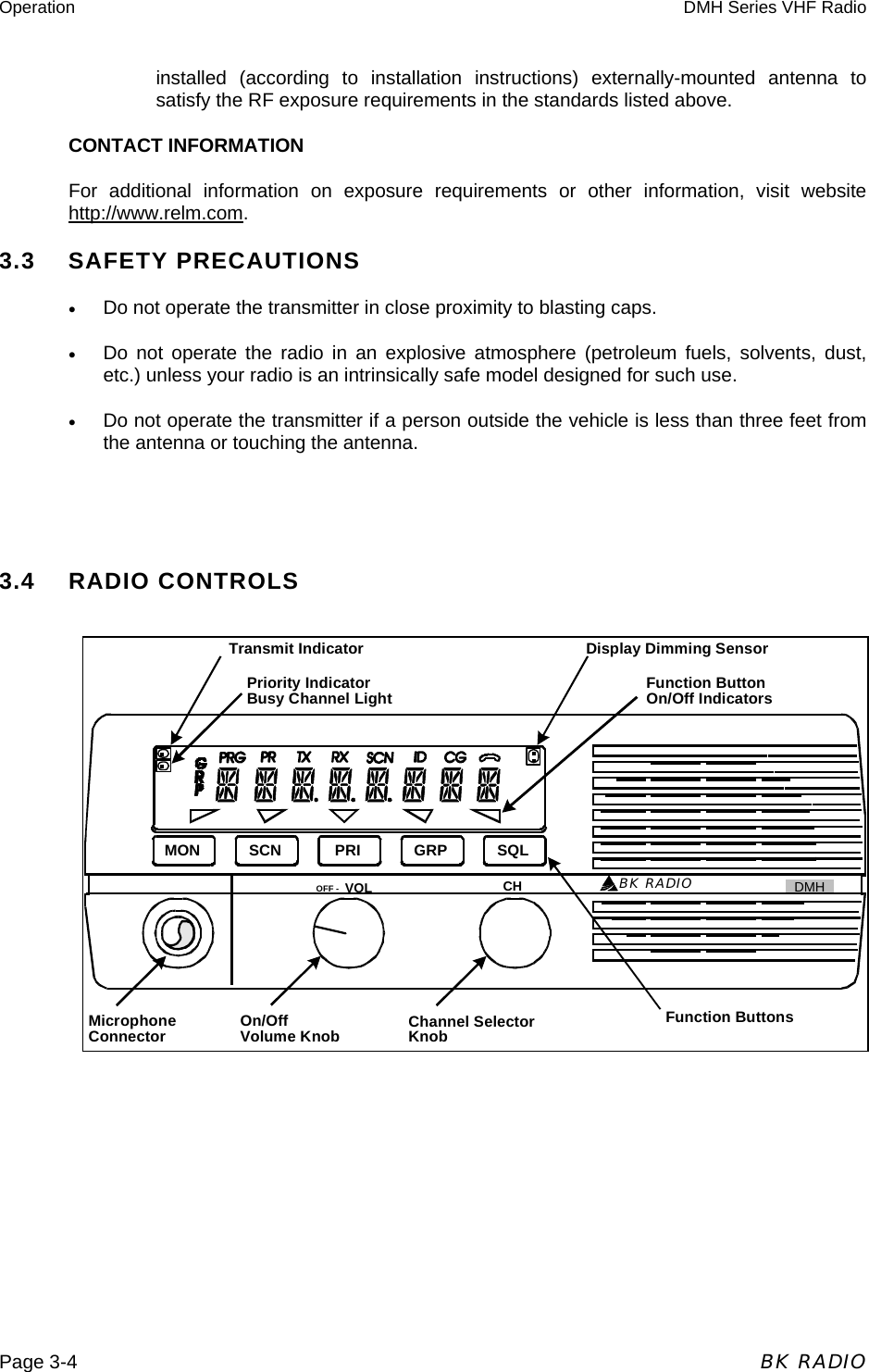
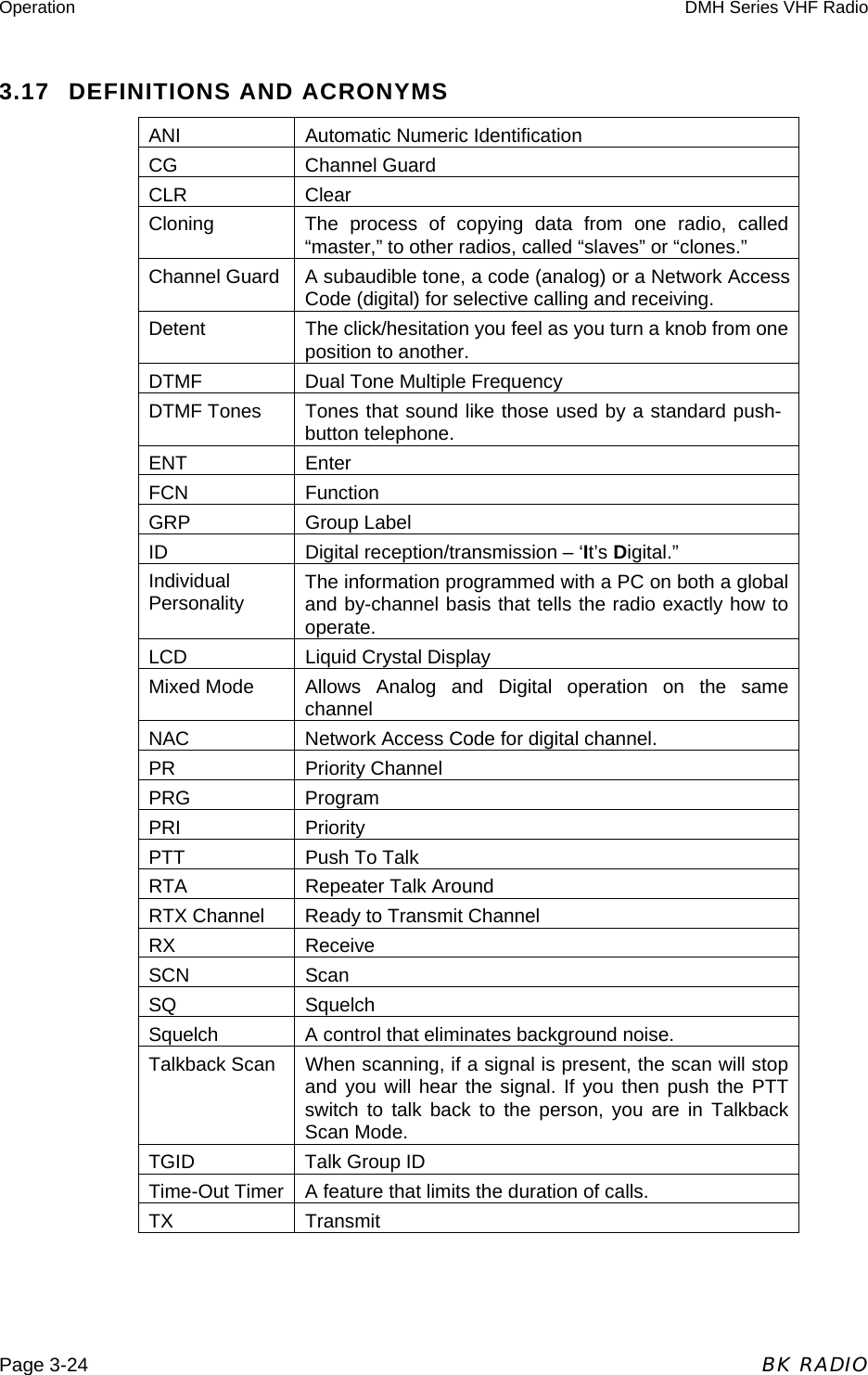
![Operation DMH Series VHF Radio BK RADIO Page 3-5 3.5 BASIC OPERATION 3.5.1 RECEIVE Turn power on by pushing and releasing the Volume knob. The radio will beep, indicating that it has passed its self test and is operational. Set volume by pressing the [MON] button to hear squelch noise. Turn the Volume knob to set a comfortable volume level. Press the [MON] button again to stop squelch noise. Select a channel group (if applicable) by pressing the [GRP] button and turning the Channel Selector knob. Press the [GRP] button again to return to Channel Select mode. Select a channel by turning the Channel Selector knob. After reaching the highest number, the radio wraps to Channel 1. The display can show channel numbers (numeric mode), channel labels (alphanumeric mode), or receive and transmit frequencies. The Display mode and Channel Labels are programmed by the technician along with group labels (if applicable) and channel frequencies. The display shows slightly different indications during Channel Scan and Priority Scan operation in alphanumeric and numeric modes. 3.5.2 TRANSMIT Press the PTT (Push To Talk) switch on the microphone. The TX annunciator appears on the display and the red Transmit indicator illuminates while the PTT is pressed. Talk in a normal voice with the microphone approximately one to two inches from your mouth. Release the PTT switch to stop transmitting. If the TX annunciator does not appear and a tone is heard, you are on a receive-only channel or the channel is busy (if Busy Channel Lockout is enabled). Turn the Channel Selector knob to an authorized transmit channel or wait until the channel is clear (if Busy Channel Lockout is installed). If the length of your transmission exceeds the preset Time-Out Timer setting, the transmitter automatically shuts off and a tone sounds. To continue the transmission, release the PTT switch, and then press it again and continue talking. 3.6 CHANNEL GUARD OPERATION Channel Guard allows one radio or group of radios to be selectively called within a system. If the radio has been programmed with Channel Guard, use the following receive and transmit instructions. 3.6.1 ANALOG SQUELCH CONTROL Sub-audible signaling (CTCSS/CDCSS) is used to allow a group of radios to be selectively called in a system. Programming the receive guard equal to zero allows for Carrier Squelch operation, where the radio will unmute whenever a carrier is detected.](https://usermanual.wiki/BK-Technologies/DMH599/User-Guide-553978-Page-5.png)
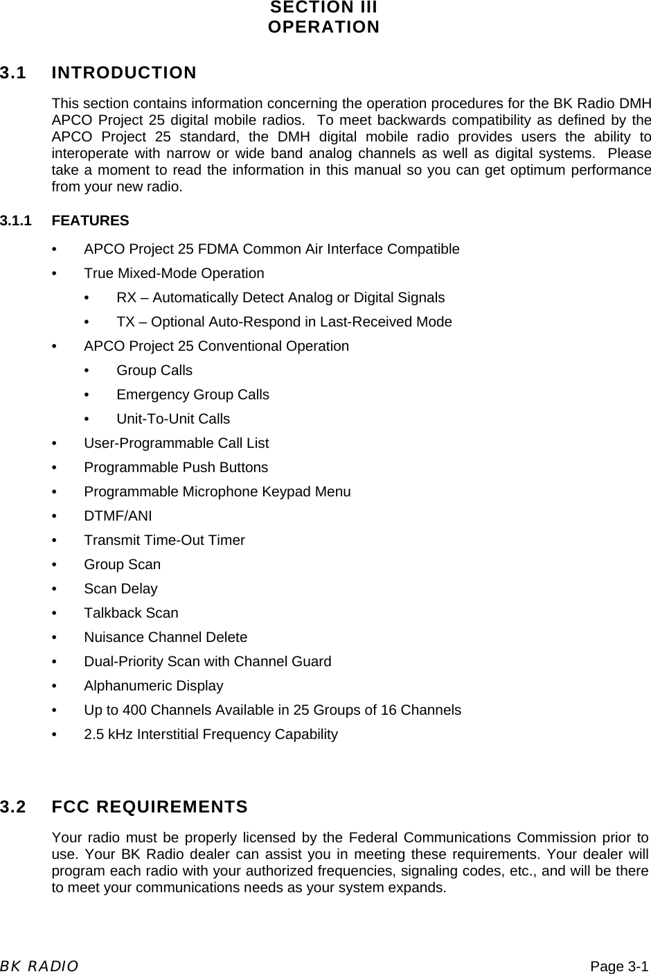
![Operation DMH Series VHF Radio Page 3-6 BK RADIO 3.6.2 APCO PROJECT 25 SQUELCH CONTROL Network Access Codes (NACs) provide the digital equivalent of analog sub-audible signaling (CTCSS/CDCSS) allowing a group of radios to be selectively called within a system. Users in the same area (using the same NAC) can be further divided into Talk Groups, with each group having its own Talk Group ID (TGID). Group Calls are made by designating both the users’ NAC and TGID. Each radio also has an individual P25 unit ID. A Unit-to-Unit call contains the addressee’s NAC, and uses the addressee’s P25 unit ID instead of the TGID. When operating in Digital Mode, each channel can be programmed to use either Normal squelch or Selective squelch. A. Normal Squelch Normal squelch is used to mimic analog operation. Signals are only qualified with the programmed NAC. TGIDs and P25 Unit IDs are ignored. Each digital channel is programmed with a receive NAC and a transmit NAC. When an incoming signal’s NAC matches the channel’s programmed receive NAC, the radio unmutes. The default NAC is 659 ($293 hex). The digital equivalent of carrier squelch is achieved by programming the receive NAC = 3966($F7E hex) the radio will unmute when a digital signal with any NAC is detected. The 3966 ($F7E hex) NAC is reserved for receivers and is not allowed as a transmit NAC. B. Selective Squelch Selective squelch is used for processing ‘Group Calls’ and ‘Unit-to-Unit Calls’. TGIDs are assigned on a per-channel basis. Users can be separated into Talk Groups with each group having its own TGID. Then, on channels programmed for Selective squelch, the incoming signal’s NAC and TGID must match the channels programmed receive NAC and TGID for the radio to unmute. The default TGID is 1. The TGID value 65535 ($FFFF hex) is used to effect an “All Call”. If the radio receives a signal with a matching NAC and the TGID = 65535 ($FFFF hex), it will unmute. Also, if the radio’s programmed TGID is 65535 ($FFFF hex), it will open on any signal with a matching NAC, ignoring the incoming TGID. A TGID = 0 means “no one”. If the radio is programmed with the TGID = 0, it will accept incoming group calls containing the “All Call” TGID, and correctly addressed Unit-to-Unit calls. 3.6.3 CHANNEL GUARD RECEIVE Turn power on by pushing and releasing the Volume knob. The radio will beep, indicating that it has passed its self test and is operational. Set volume by pressing the [MON] button to hear squelch noise. Turn the Volume knob to set a comfortable volume level. Press the [MON] button again to stop squelch noise. Select a channel group (if applicable) by pressing the [GRP] button and turning the Channel Selector knob. Press the [GRP] button again to return to Channel Select mode.](https://usermanual.wiki/BK-Technologies/DMH599/User-Guide-553978-Page-6.png)
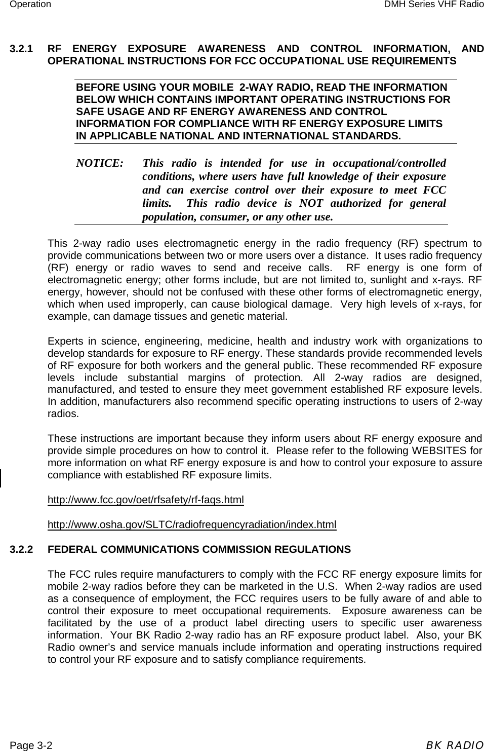
![Operation DMH Series VHF Radio BK RADIO Page 3-7 Select a channel by turning the Channel Selector knob. Press the [CG] button to disable or enable Channel Guard operation on analog channels. An arrow on the display points to the [CG] button when Channel Guard is disabled. When Channel Guard is enabled, a message is heard only when the proper Channel Guard is received. 3.6.4 CHANNEL GUARD TRANSMIT Monitor the channel, before transmitting on Channel Guard channels, by lifting the microphone off hook or pressing the [MON] button. Listen to the channel for a few seconds to ensure that no communications are occurring on the channel. Press the PTT (Push To Talk) switch on the microphone. The TX annunciator appears on the display and the red Transmit indicator illuminates while the PTT is pressed. Talk in a normal voice with the microphone approximately one to two inches from your mouth. Release the PTT switch to stop transmitting. Hang up the microphone when finished. If you pressed the [MON] button to monitor the channel, press it again after the transmission to return to Channel Guard operation. 3.7 MIXED MODE OPERATION The receiver and transmitter are capable of operating in analog wide-band (25 kHz channel spacing), analog narrow-band (12.5 kHz channel spacing) and APCO Project 25 Digital Mode. Each channel’s Receive and Transmit Mode can be set independently as follows: Mode RX TX Analog Receive qualified analog signals only Transmit analog signals only Digital Receive qualified digital signals only Transmit digital signals only Mixed Automatically receive qualified analog or digital signals Transmit analog or digital signal, depending on the status of ‘TX Digital’ soft switch. Digital receptions and transmissions will be indicated by illuminating the ‘ID’ annunciator in addition to the ‘RX’ or ‘TX’ annunciator. 3.7.1 MIXED MODE TALKBACK If Mixed Mode Talkback is enabled, transmissions initiated while hold time remains will be in the same mode as the received signal, if the signal was received on the Ready to Transmit (RTX) channel. Depending on programming, the RTX channel can be the main channel, a held scan or priority channel if Talkback Scan is enabled, or the Priority 1 channel if TX on PR1 is enabled. TX Mode on the RTX channel must be set to MIXED. While hold time after a reception remains, transmissions will be in the same mode as the received signal, regardless of the status of the ‘TX Digital’ soft switch. As in](https://usermanual.wiki/BK-Technologies/DMH599/User-Guide-553978-Page-7.png)
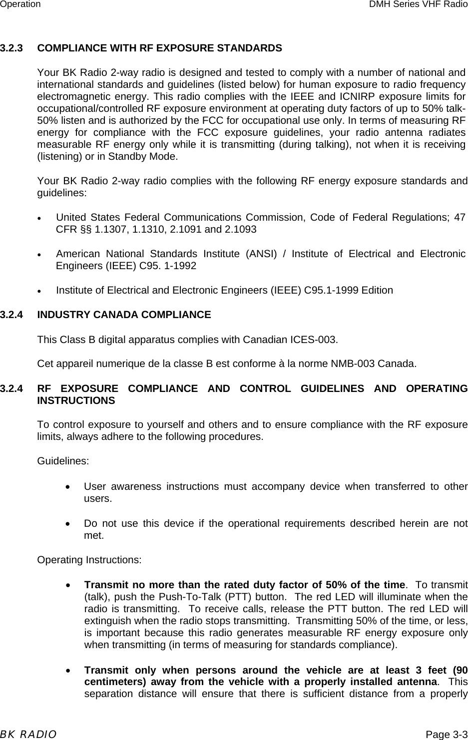
![Operation DMH Series VHF Radio Page 3-8 BK RADIO Talkback Scan, the RTX channel and receive annunciators will be displayed for the duration of the timer. The talkback timer can be cleared by making the held channel invalid. For instance, if a scan channel is being held, turn scan off. 3.8 PROGRAMMABLE PUSH BUTTONS/MICROPHONE FCN KEY FUNCTION MENU When the radio is installed, labels are placed on the front push buttons to indicate their functions. An arrow on the display points to each front mounted push button that is active. The five push buttons can be programmed with the following functions: Standard Functions Optional Functions MON Monitor Squelch Noise TA Repeater Talk Around GSC Group Scan SCN Channel Scan CG Channel Guard Disable PA Public Address PRI Priority Scan HOM Home Channel ACC Accessory 1 GRP Group Select SPK Remote Speaker ACC Accessory 2 SQL Squelch Adjust NXT Next Scan Channel ACC Accessory 3 TXD Transmit Digital Mode LPW Low Power Select If a keypad microphone is used with the DMH radio, many of the functions above may also be enabled/disabled with the keypad [FCN] key. Not all microphones support these functions. Contact your dealer to determine which features are available with your microphone and have been enabled in the radio. • Press the [FCN] key to display the function menu. • Press [PRI] to toggle the function on/off when the desired menu item is displayed. • Repeatedly press [FCN] to step through the menu. • When the display flashes, the function is enabled. • Press [ENT] to exit the [FCN] menu. 3.9.1 MICROPHONE KEYPAD LOCK To lock/unlock the microphone’s keypad, press and hold the [FCN] key. When locked, “LOCKED” will be displayed if a key is pressed and a low beep will sound. LOCKOUT EXCEPTIONS: 1. If enabled, a long [PRI] key press will activate Emergency Mode even when the microphone’s keypad is locked. 2. PTT unlocks the keypad during transmit for DTMF key presses.](https://usermanual.wiki/BK-Technologies/DMH599/User-Guide-553978-Page-8.png)
![Operation DMH Series VHF Radio BK RADIO Page 3-9 3. The keypad will be automatically unlocked when Unit-To-Unit Mode is entered by pressing PTT to respond to a Unit-To-Unit call, when Unit-To-Unit callback is enabled. The keypad will be re-locked when Unit-To-Unit Mode is exited. Push button controls are described as follows: MON Monitor Squelch Noise Press the [MON] button to start or stop monitoring squelch noise. This allows you to set a comfortable volume level. SCN Channel Scan Press the [SCN] button to start or stop scanning channels in the scan list. Scan operation occurs only while the radio is not transmitting. To add or delete the current channel from the Scan List, turn Scan and Priority Scan off, then press the [SCN] button and hold it down for 1 second or more. PRI Priority Scan Press the [PRI] button to start or stop priority scanning. The PR annunciator and the flashing SCN annunciator appear on the display. To make the current channel the fixed Priority 1 Channel, turn Scan and Priority Scan off, then press the [PRI] button and hold it down for 1 second or more. GRP Group Select Press the [GRP] button to toggle between Group Select and Channel Select Modes. This is used only if the radio has more than one channel group. Press the [GRP] button for Group Select Mode. Turn the Channel Selector knob to select a group. Return to Channel Select Mode by waiting 5 seconds, or by pressing the [GRP] button one time (numeric mode) or two times (alphanumeric mode). After selecting a group in Alphanumeric Mode, press the [GRP] button one time to display the Group Label, and a second time to return to Channel Select Mode. SQL Squelch Adjust Press the [SQL] button to toggle between Squelch Adjust and Volume Adjust Modes. Press the [SQL] button for Squelch Adjust Mode. Turn the Volume knob to adjust the squelch setting. Turning the knob counter-clockwise tightens the squelch setting, allowing only stronger signals to open the squelch and be heard. In the absence of a held channel, the receiver will be tuned to the main channel. Guard qualification will be disabled during squelch adjustment. Return to Volume Adjust Mode by waiting 5 seconds, or by pressing the [SQL] button again. Pressing the [SQL] button and holding for more than 1 second sets the squelch to its factory preset value.](https://usermanual.wiki/BK-Technologies/DMH599/User-Guide-553978-Page-9.png)
![Operation DMH Series VHF Radio Page 3-10 BK RADIO TA Repeater Talk Around Press the [TA] button to turn Repeater Talk Around on or off. When TA is on, the radio transmits on the receive frequency of the selected channel, bypassing or “talking around” the repeater. This function may be used on any channel that is programmed to a frequency pair (repeater channel). CG Channel Guard Disable Press the [CG] button to disable or enable Channel Guard operation on analog channels. An arrow on the display points to the CG button when Channel Guard is disabled. When Channel Guard is enabled, a message is heard only when the proper Channel Guard is received. Transmit Channel Guard generation is unaffected. The CG button may also be used to override Busy Channel Lockout, if Busy Channel Override is installed. HOM Home Channel Press the [HOM] button to go to the pre-programmed Home Channel. To set a different Home Channel, select the desired channel using the Channel Selector knob, press the [HOM] button, and hold it for more than 1 second until the arrow above the HOM button appears on the display. The new channel then becomes the Home Channel. SPK Remote Speaker Press the [SPK] button to toggle between the built-in radio speaker and a remotely mounted speaker. NXT Next Scan Channel Press the [NXT] button to select the next consecutive channel in the Scan List (not during scan operation). LPW Low Power Select Press the [LPW] button to toggle between high power and low power transmitter operation. Transmitter power settings can be programmed from 15 to 50 watts. If per-channel power is enabled, channels locked to low power will always transmit in low power mode regardless of the state of the LPW button. GSC Group Scan Press the [GSC] button to enable or disable Group Scan operation. During Group Scan operation, the following features are disabled: Priority Scan, User Channel Guard, and Nuisance Channel Delete. Turn Group Scan off, then press the [GSC] button for 1 second or more to toggle the current group on or off the Group Scan List.](https://usermanual.wiki/BK-Technologies/DMH599/User-Guide-553978-Page-10.png)
![Operation DMH Series VHF Radio BK RADIO Page 3-11 PA Public Address Press the [PA] button to turn the Public Address system on or off. When PA is on, pressing the microphone PTT switch causes audio to be routed to the audio amplifier without enabling the transmitter. ACC Accessory Press the [ACC] button to turn the installed accessory on or off. Up to three ACC buttons may be installed for different accessories. 3.10 SCAN OPERATION 3.3.1 Receive Scan operates only while the radio is not transmitting. The radio checks for signals on channels in the preset scan list, as well as the channel selected by the Channel Selector knob. When a signal is detected, scanning stops and the message is received. The received channel is shown in place of the transmit channel. Once the signal ends, the radio continues to monitor the channel for the preset scan delay time before it resumes scanning. 3.3.1.1 Basic Scan 1. Press the SCN button to enable Scan (an arrow will appear above the button). 2. If Priority Scan is enabled, press the PRI button to turn it off. The display indicates Scan operation by flashing the SCN annunciator (alphanumeric mode) or by two flashing bars (numeric mode). 3.10.1 SCAN CHANNEL GUARD CHANNELS 1. Press the SCN button to enable Scan (an arrow will appear above the button). 2. If the CG button has an arrow over it, press the CG button once to turn Code Guard Disable off. When a signal is detected, scanning stops while the radio checks for the proper Code Guard value. If the signal contains the proper Code Guard value, the radio receives the message. Otherwise, the radio resumes scanning immediately. 3.10.2 NUISANCE CHANNEL DELETE With Channel Scan on and Nuisance Channel Delete enabled, pressing and holding the [SCN] button for more than 1 second will temporarily remove a currently active channel from the Scan List. If the radio is equipped with a keypad microphone, pressing the [CLR] key while Scan is on will accomplish the same thing. Not all microphones support these functions. Contact your dealer to determine which features are available with your microphone and have been enabled in the radio. When the radio is powered off and back on, the pre-programmed Scan List will be](https://usermanual.wiki/BK-Technologies/DMH599/User-Guide-553978-Page-11.png)
![Operation DMH Series VHF Radio Page 3-12 BK RADIO restored. 3.10.3 TRANSMIT WITH SCAN ON When operating in Scan mode, the radio transmits on the channel selected by the Channel Selector knob. 1. Select a transmit channel by turning the Channel Selector knob. 2. Press and hold the PTT switch and talk in a normal voice. When the PTT switch is released, the radio continues to monitor the selected channel for the preset scan delay time before it resumes scanning. 3.10.4 TALKBACK SCAN If your radio is programmed for Talkback Scan, press PTT while a channel is active or while scan delay time remains. You will be responding on the transmit frequency of the received channel. Talkback Scan will not work if Priority Scan is also on and your radio is programmed to always transmit on the Priority 1 channel. 3.10.5 CHANGE THE SCAN LIST The radio can be programmed to enable the user to add or remove channels from the scan list. If user changes are enabled, follow these steps to change the scan list: 1. Turn Scan and Priority Scan off. 2. Select a channel to be added or removed from the scan list by turning the Channel Selector knob. If the channel is already on the scan list, SCN appears in the display. 3. Press and hold the [SCN] button for more than 1 second to toggle the channel on or off the scan list. 3.10.6 GROUP SCAN Channels on each "Channel Scan List" in groups on the "Group Scan List" are scanned sequentially. The selected group is always scanned when Group Scan is enabled, even if that group is not on the Group Scan List. When Group Scan is enabled, the following features are disabled: • Priority Scan • Dual Priority Scan • User-Selected Channel Guard • Nuisance Channel Delete](https://usermanual.wiki/BK-Technologies/DMH599/User-Guide-553978-Page-12.png)
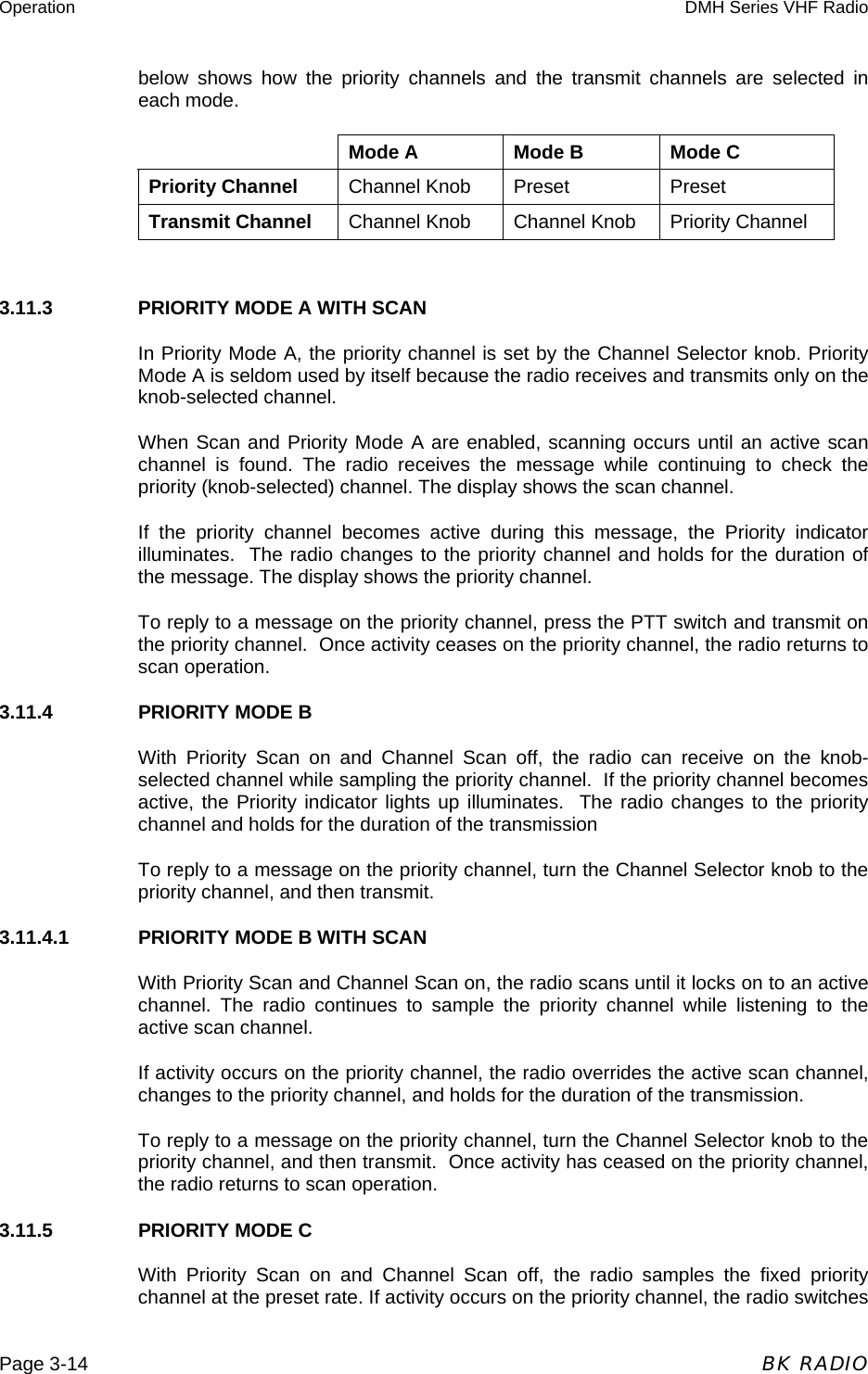
![Operation DMH Series VHF Radio BK RADIO Page 3-13 3.11 PRIORITY SCAN Priority Scan enables the radio to receive on any channel while monitoring for a message on the designated priority channel(s). The radio samples each priority channel at a preset rate (.25-2.0 seconds) regardless of activity on any other channel. Priority Scan operates only while the radio is not transmitting and can be used in combination with scan operation. When Priority Scan is on, the PR annunciator illuminates, and the display flashes SCN (alphanumeric mode) or two flashing bars (numeric mode). If a message is received on a priority channel, the Priority indicator illuminates, and the radio receiver locks onto that channel for the duration of the transmission, unless a higher priority channel interrupts. Priority Scan can be used in combination with Channel Guard with: • Priority Scan on (arrow appears above PRI button) • The Squelch knob in the Channel Guard position (fully counterclockwise detent position) and • Channel Guard Disable off (no arrow above CG button) • The Priority Channel(s) programmed with Channel Guard If a message is received on a priority channel, the radio receiver locks on to the priority channel and checks to see if the proper Channel Guard value is present. If the signal contains the proper Channel Guard value, the radio receives the message. Otherwise, the radio will re-check the channel every 4 seconds, until the activity on the channel ceases. 3.11.1 DUAL PRIORITY SCAN In each group, up to two of the 16 channels can be designated as priority channels. These two, PR1 and PR2, are periodically tested for activity, even if a different transmission is being listened to. Activity on PR2 preempts activity on any of the non-priority channels. Receptions on PR1 have priority over any other channel in the group, including PR2. Either priority channel can be programmed as a fixed channel, tied to the Channel Selector knob, or programmed OFF. If the radio is programmed to transmit on the first priority channel, transmissions will occur on PR1 if PR1 isn’t programmed OFF, when operating in Dual Priority Scan Mode. If PR1 is a fixed channel, and changes to the 1st priority channel are allowed, and the [PRI] key is not locked out, the user can move the channel selector to a new channel and press and hold the [PRI] button for more than 1 second to choose a new PR1 channel. Dual Priority Scan is automatically disabled when Group Scan is on. 3.11.2 OLD-STYLE BK PRIORITY SCAN The radio can be programmed with one of three Priority Modes: A, B, or C. The table](https://usermanual.wiki/BK-Technologies/DMH599/User-Guide-553978-Page-13.png)
![Operation DMH Series VHF Radio BK RADIO Page 3-15 to the priority channel and holds for the duration of the transmission. To reply to a message heard on the priority channel, press the PTT switch. The radio transmits only on the priority channel when Priority Scan is on. Once activity has ceased on the priority channel, the radio returns to the receive channel on the Channel Selector knob. 3.11.5.1 PRIORITY MODE C WITH SCAN With Priority Scan and Channel Scan on, the radio scans until it locks on to an active channel. The radio continues to sample the priority channel while listening to the active channel. If activity occurs on the priority channel, the radio overrides the active scan channel, changes to the priority channel, and holds for the duration of the transmission. To reply to a message heard on the priority channel, press the PTT switch. The radio transmits only on the priority channel when Priority Scan is on. Once activity has ceased on the priority channel, the radio returns to scan operation. 3.11.6 CHANGE THE PRIORITY 1 CHANNEL The fixed Priority 1 channel can be permanently set or can be changeable. If the radio has a changeable priority channel, use the following steps to make this change. 1. Turn Scan and Priority Scan off. 2. Turn the Channel Selector knob to the channel you want to enter as the new Priority 1 channel. 3. Press and hold the [PRI] button for more than 1 second. A short beep sounds and PR appears in the display, indicating that the displayed channel is now the priority channel. NOTE: If the radio is programmed for Dual Priority operation, only Priority 1 channel can be changed with the [PRI] button. NOTE: A channel can be the priority channel even if it is on the Scan List. Due to multiple sampling of the same channel, however, maximum performance occurs when the priority channel is not on the Scan List. 3.12 UNIT-TO-UNIT CALL P25 Unit IDs allow for Unit-To-Unit calls when the radio is operating in Digital Mode. The microphone’s [*] key must be enabled by radio programming to allow this mode of operation. To view the radio’s ID, press and hold the [*] key while not in Unit-To-Unit Mode. (Unit-To-Unit Mode is indicated by a phone icon in the upper right corner of the display). Channels programmed for analog only operation will not be able to transmit or receive Unit-To-Unit calls. 3.12.1 UNIT-TO-UNIT MODE When the radio is in Unit-To-Unit Mode, all scanning functions will be disabled. The radio will receive and transmit on the Ready-to-Transmit (RTX) channel only. Depending on programming, the RTX channel can be the main channel, a held scan](https://usermanual.wiki/BK-Technologies/DMH599/User-Guide-553978-Page-15.png)
![Operation DMH Series VHF Radio Page 3-16 BK RADIO or priority channel if Talkback Scan is enabled, or the Priority 1 channel if TX on PR1 is enabled. To alert the user that the radio is in Unit-To-Unit Mode, a beep will periodically sound until the unit is returned to normal Operating Mode. If the RTX channel’s Digital Squelch Mode is set to ‘selective’, the radio will accept group calls, correctly addressed Unit-To-Unit calls, and if RX Mode is set to mixed, analog signals. When a correctly addressed Unit-To-Unit call is received, the radio will beep twice. If the calling unit’s ID matches one of the Call List IDs, the associated label will be displayed along with the RX and phone icon. Otherwise, the numeric ID will be displayed along with the RX, ID, and phone icon. If the calling unit is not the same unit displayed before the call was received, the calling unit’s ID will be displayed for the duration of the reception. The previously displayed ID will remain the default transmit ID, but the interrupting ID will be captured as ‘last active’. To speak to the interrupting caller, press [*] to make the last active ID the new default transmit ID. When a group call (or, if allowed, an analog signal) is received, the radio will display the RTX channel’s label for the duration of the reception. If the RTX channel’s Digital Squelch Mode is set to ‘normal’, the radio performs as when the Squelch Mode is ‘selective’, except all individual calls will be received when the incoming NAC matches the channel’s programmed receive NAC, not just individual calls addressed to the unit. Individual calls not addressed to the unit will be indistinguishable from group calls. Only the channel label will be displayed, not the ID of the calling unit. If Unit-To-Unit Mode is entered when the RTX channel is programmed for analog-only transmissions, pressing PTT will cause the radio to beep until PTT is released. The user must select a channel capable of digital transmissions before placing a Unit-To-Unit call. If the RTX channel is programmed for Mixed Mode transmit, transmissions will be made as digital Unit-To-Unit calls while the radio is in Unit-To-Unit Mode, regardless of the position of the ‘TX Digital’ switch. 3.12.2 INITIATING A UNIT-TO-UNIT CALL To initiate a Unit-To-Unit call, press the microphone’s [*] key to enter Unit-To-Unit Mode. The label of the last active (called or received) ID will appear on the display. If the last active ID was a Call List ID, its label will be displayed along with the phone icon, otherwise the numeric ID will be displayed along with the phone and ID icon. If a label is displayed, press and hold [#] to view the corresponding numeric ID. To place a call to the displayed unit, press PTT. To choose another unit, use the keypad to enter the desired call list entry (0 - 9), or press [PRI] repeatedly to cycle through all call list entries, or press [#] to manually key in a new ID (up to 7 digits). To re-select the ‘last active’ ID, press the [*] key. Once the new unit ID is selected or entered, press PTT to place the call. To exit Unit-To-Unit Mode, press and hold the [*] key. 3.12.3 RECEIVING A UNIT-TO-UNIT CALL When a Unit-To-Unit call is received while the radio is in normal Operating Mode, the](https://usermanual.wiki/BK-Technologies/DMH599/User-Guide-553978-Page-16.png)
![Operation DMH Series VHF Radio BK RADIO Page 3-17 radio will beep twice. The display will show the ID of the calling unit. If the ID matches one of the Call List IDs, the associated label will be displayed along with the RX and phone icons. Otherwise the numeric ID will be displayed along with the RX, phone, and ID icons. The calling unit’s ID will be displayed for the duration of the reception, and once the signal goes away, for a programmed hold time. When the hold time expires, the display will return to the normal Operating Mode display, but the phone icon will flash until the [*] key is pressed, putting the radio in Unit-To-Unit Mode, displaying the last active ID. 3.12.4 UNIT-TO-UNIT CALLBACK If Unit-To-Unit callback is enabled, and a Unit-To-Unit call is received on the Ready-to-Transmit (RTX) channel, the user may press PTT before the hold time expires, causing the radio to enter Unit-To-Unit Mode and transmit using the received ID as the destination ID. If the callback timer expires before PTT is pressed, the radio will return to normal Operating Mode, but the phone icon will flash until the [*] key is pressed, bringing up the last active ID. To exit Unit-To-Unit Mode, press and hold the [*] key. The callback timer can be cleared by making the held channel invalid. For instance, if a scan channel is being held, turn scan off. 3.12.5 PROGRAMMING UNIT-TO-UNIT CALL LIST Press [*] to bring up the last active ID. If the last active ID was a Call List ID, the ID’s label will be displayed along with the phone icon. Otherwise, the ID number will be displayed along with the phone and ID icon. Press a number key (0 – 9) to go directly to the desired Call List ID, or press [PRI] repeatedly to cycle to the label of the ID to be re-programmed. Press and hold the [FCN] key to enter ID Programming Mode (PRG icon will be illuminated). As in keypad Programming Mode, normal radio function will be disabled until ID Programming Mode is exited. 3.12.6 PROGRAMMING A LABEL Press the [CLR] key. The display becomes blank. Press number keys to enter 0-9 in positions 1-7. The digits start in position 7, then move left. 1. Press the [#] key to toggle a decimal on or off to the right of the character in position 7. The decimal moves left with the number in position 7 as new numbers are entered. 2. Use the following steps to enter a number in position 8 or characters in positions 1-8: a. Press the [PRI] key repeatedly to cycle through characters 0-9, A-Z, -, *, $, /, +, %, \, |, _, <, >, h, blank, then back to the start again. If you pass the desired character, press the [PRI] key repeatedly until you return to the start and reach that character again.](https://usermanual.wiki/BK-Technologies/DMH599/User-Guide-553978-Page-17.png)
![Operation DMH Series VHF Radio Page 3-18 BK RADIO b. Press the [FCN] key to shift the display left by one position, leaving position 8 blank. c. Press the [PRI] key repeatedly to enter the next character, or press the [FCN] key a second time to enter a blank space. d. To abandon changes, press the [CLR] key, restoring the original label. e. Press the [ENT] key to store changes. 3.12.7 PROGRAMMING A NUMERIC ID Press [ENT] to display the numeric ID. Press [CLR] enter the new ID (up to 7 digits). Press [ENT] to store the new ID. Select a new ID to be programmed, or press and hold [ENT] to exit Programming Mode (the PRG annunciator will be extinguished). 3.13 EMERGENCY CALL Note: Emergency operation only applies to channels programmed for Digital or Mixed Mode transmissions. If the channel is programmed for Mixed Mode transmissions, the ‘TX Digital’ switch must be ON. To place an emergency group call, press and hold the emergency button until the radio beeps and the display flashes. On some models, the emergency button may be the microphone’s [PRI] key. All scanning and priority scanning functions will be disabled. If the radio is in Unit-To-Unit Mode, that mode will be exited and the radio will be placed in Emergency Mode. Each subsequent press of PTT will cause the radio to transmit on the knob-selected channel with the emergency bit set, indicating an emergency condition. If the Channel Selector is changed, the Emergency Mode will follow to the newly selected channel. Cycle power to return the radio to normal operation. On channels programmed for analog transmissions, and channels programmed for Mixed Mode transmissions with the ‘TX Digital’ switch OFF, pressing PTT in Emergency Mode will result in a normal analog transmission.](https://usermanual.wiki/BK-Technologies/DMH599/User-Guide-553978-Page-18.png)
![Operation DMH Series VHF Radio BK RADIO Page 3-19 3.14 USER SELECTED CHANNEL GUARD User Selected Channel Guard is only available on radios equipped with a keypad microphone. Not all microphones support this function. Contact your dealer to determine which features are available with your microphone and have been enabled in the radio. When the radio is being programmed with transmit and receive frequencies for each channel, a receive Channel Guard value and a transmit Channel Guard value can also be assigned to each channel. If User Channel Guard Selection is enabled, the Channel Guard values for any channel can be copied to another channel in the radio. On channels programmed for Analog operation only, the CTCSS or CDCSS guard values will be copied. On channels programmed for Digital operation only, NAC’s only will be copied unless the radio is programmed to also copy the Talk Group ID (TGID), Mode (Digital, Analog or Mixed) and Squelch setting (Normal or Selective). On Mixed Mode channels, Analog or Digital values will be copied as needed. For example, to use the Channel Guard values of Channel 9 with the frequencies of Channel 5: 1. Turn Scan and Priority Scan OFF. 2. Turn the Channel Selector knob to Channel 5. 3. Press the [9] key on the microphone keypad. The display shows CG. The radio will now operate on the frequencies of Channel 5 with Channel 9 Channel Guard values. The display shows the Channel Guard channel (9), and then the selected channel (5). 4. Press the microphone’s [#] key to display the Channel Guard channel briefly. The display shows the group number, followed by the Channel Guard channel, and then the selected channel. 5. Press the [0] key to reset all values to the original programming, or press different number keys (1-16) to select a different set of Channel Guard Values. NOTE: During Scan or Priority Scan, the receiver does not use the user-selected Channel Guard values. However, user-selected Channel Guard values are used by the transmitter in Scan Mode. 3.15 OTHER OPERATIONAL FEATURES The BK Radio D Series radio is based on a microprocessor core that allows extra features and operational characteristics to be programmed into the radio. Your dealer can help define the best operational settings for your system and program them into the radio. 3.15.1 SCAN DELAY Scan delay lets the radio receive a response to a transmission before scanning the other channels for activity. If you find that your scanner is restarting before message replies are received, you can ask your dealer to increase the scan delay time (0-7.5 seconds).](https://usermanual.wiki/BK-Technologies/DMH599/User-Guide-553978-Page-19.png)
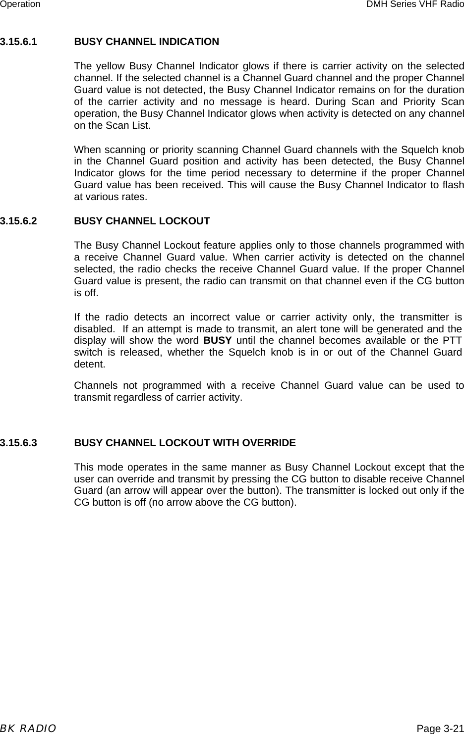
![Operation DMH Series VHF Radio Page 3-20 BK RADIO This timer is also used to allow for Talkback Scan, Mixed Mode Talkback, and Unit-To-Unit Callback. 3.15.2 HI/LO POWER Each channel in the radio can be individually programmed to always transmit in low-power mode, regardless of the position of the radio's LPW button (or microphone keypad [FCN] menu setting). If the programming for the channel allows high-power transmissions, the power level can be selected with the LPW button or the keypad [FCN] menu. 3.15.3 DTMF ENCODING (Analog Mode Only) Radios with keypad-equipped microphones can be programmed to enable DTMF (Dual Tone Multiple Frequency) encoding. To send DTMF tones (similar to the tones used by a standard push-button telephone): 1. Press and hold the PTT switch. 2. Press any of the keys on the microphone’s keypad. You will hear a sidetone. The FCN, PRI, ENT, and CLR keys respond as DTMF tones A, B, C, and D, respectively. 3.15.4 ANI ENCODING (Analog Mode Only) ANI encoding (Automatic Number Identification), if enabled, transmits a sequence of DTMF tones each time you press the PTT switch. You will hear a sidetone. Your dealer can program the ANI number to be sent. If DTMF and ANI are both enabled, the ANI tone sequence is transmitted only after the microphone’s [ENT] key is pressed while the PTT switch is activated. You will hear a sidetone. 3.15.5 TIME-OUT TIMER The transmit Time-Out Timer limits the duration of calls and guards against accidentally locking on the transmitter and tying up the radio system. Your dealer can program the duration of the Time-Out Timer (15-225 seconds, or disabled). 3.15.6 BUSY CHANNEL If the radio has been programmed for Busy Channel operation, it will operate in one of the following three Modes: • Busy Channel Indication • Busy Channel Lockout • Busy Channel Lockout with Override](https://usermanual.wiki/BK-Technologies/DMH599/User-Guide-553978-Page-20.png)
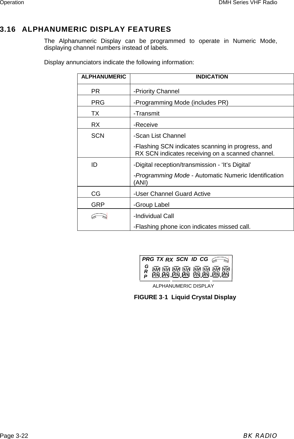
![Operation DMH Series VHF Radio BK RADIO Page 3-23 DMH Series mobile radios can be programmed with the following features: 3.16.2 CHANNEL LABELS You can program the radio with a label for each of the 25 channel groups and a label for each of the 16 channels within each group. To display the channel number associated with a channel label: 1. Press the microphone’s [#] key to display the group number. 2. Press the [#] key again to display the channel number. 3. Press and hold the [#] key to display the channel label. 4. Press the [ENT] key or wait for about 5 seconds to revert to normal radio operation. Each label can include up to eight characters, with decimal points available between characters. Characters can include A-Z, 0-9, -, *, $, /, +, %, \, |, _, <, >, h, or a blank space. 3.16.3 GROUP LABELS The display can show group labels in addition to group numbers. To display a group label, turn scanning functions off, then: 1. Press the microphone’s [#] key to display the group number. 2. Press and hold the [#] key to display the group label. 3. Press the [ENT] key or wait for about 5 seconds to revert to normal radio operation.](https://usermanual.wiki/BK-Technologies/DMH599/User-Guide-553978-Page-23.png)