BK Technologies GMH599 VHF Mobile Transceiver User Manual Manual Section 2
RELM WIRELESS CORP. - BK RADIO VHF Mobile Transceiver Manual Section 2
UserManual.wiki
>
BK Technologies
>
GMH599 User Manual
>
Manual Section 2
Contents
1.
Manual Section 1
2.
Manual Section 2
3.
Users Manual Section 3
4.
Users Manual Section 4
5.
Users Manual Section 5
6.
Users Manual Section 6
Manual Section 2
Navigation menu
Upload a User Manual
Namespaces
Wiki Guide
HTML
PDF
Info
Views
User Manual
Discussion / Help
Navigation
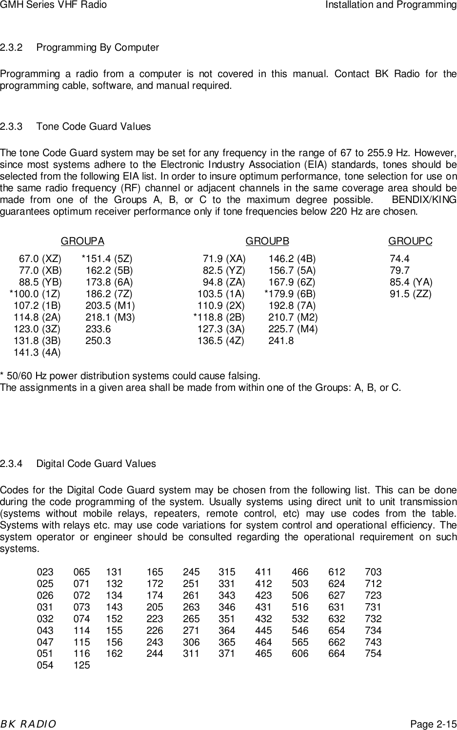
![GMH Series VHF Radio Installation and ProgrammingBK RADIOPage 2-32.2 KEYBOARD PROGRAMMINGGMH Series radios can be programmed in three different ways:A. With a computer, GMH tuning software, and an LAA 0725 interface cable. That procedure isnot described in this manual.B. With the optional LAA 0290 keyboard microphone. That procedure is described in thissection.C. With an LAA 0700 cloning cable, clone programmed settings (except Alphanumeric displaysettings) from a BK Radio portable radio with a keyboard and display, and with the samefrequency band as the GMH. That procedure is described on page 2-12.2.2.1 Enter Programming Mode1. Select a channel group to be programmed (ifapplicable) by pressing the GRP button and rotatingthe Channel Select knob. Press the GRP buttonagain to return to channel select mode.2. Press and hold the far right pushbutton on the frontof the radio.3. While holding the far right pushbutton, press andhold the [FCN] key on the microphone. After aboutthree seconds the display will show - - - ID.4. Release the [FCN] key and the right pushbutton.The radio is now in the password entry mode.5. Enter the six-digit password code. Without thecorrect password code, you cannot proceed withprogramming.NOTE: New radios shipped from the factory areassigned the password code 000000.While entering the password code the display willnot change, but a beep will sound for each keypressed. If the password code is entered incorrectly,the radio will reset to normal operation. Try again,starting at step 2.6. To keep the password unchanged, press the [ENT]key on the microphone and continue with normalradio programming.To change the password, press the [FCN] key andenter a new six-digit password code. The digits aredisplayed as you enter them.NOTE: Do not use a 1 for the first digit of thepassword code – the radio will malfunction.The password code can contain the digits 0through 9, *, and #.If you make an error entering the new passwordcode, press the [CLR] key on the microphone andtry again.](https://usermanual.wiki/BK-Technologies/GMH599.Manual-Section-2/User-Guide-101842-Page-3.png)
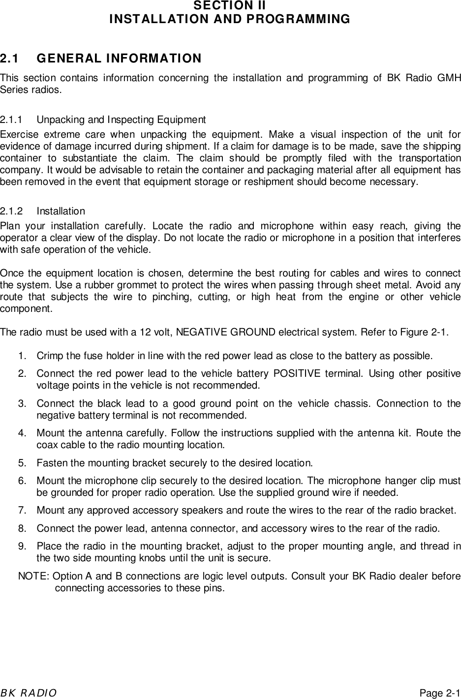
![Installation and Programming GMH Series VHF RadioPage 2-4BK RADIO7. Press the [ENT] key to store the new password andproceed to programming mode. The display willchange to PRG Ch 000.2.2.2 General Performance Variables (Channel 0)Channel 0 settings for each group must be programmed separately. Select the group to beprogrammed (if applicable) by pressing the GRP button an rotating the Channel Select knob. Pressthe GRP button again to return toe Channel Select mode.The same password is used for all groups in the radio.NOTE: Settings listed as Group One functions, Group Two functions, and Group Three functionsrefer to programming function groups, not channel groups.Press the [FCN] key on the keyboard repeatedly to view the settings in Channel 0, then loop back tothe CH 000 entry point. Channel 0 settings include:Automatic Number Identification (ANI)Transmitter Timeout TimerScan Delay TimeGroup One functions: 1-12345Priority Scan OperationPriority Key LockoutScan List LockoutGroup Two functions: 2-12345Enable User Code GuardBusy Channel OperationANI EnableDTMF EnableGroup Label2.2.2.1 Automatic Number Identification (ANI)1. After entering the programming mode the display willshow PRG Ch 000.2. Press the [FCN] key.3. The display will indicate the ANI ID number (as manyas seven digits may be used). The ID number canbe used for either radio management or transmittedas a DTMF tone burst for ANI purposes. The ANIcan be enabled or disabled. See “ANI Enable” onpage 2-8.4a. If no change is needed for the ID number, press the[FCN] key to advance to the next section.4b. A new number can be entered by pressing the[CLR] key, followed by number keys. The digits willappear at the right of display and move to the left.](https://usermanual.wiki/BK-Technologies/GMH599.Manual-Section-2/User-Guide-101842-Page-4.png)
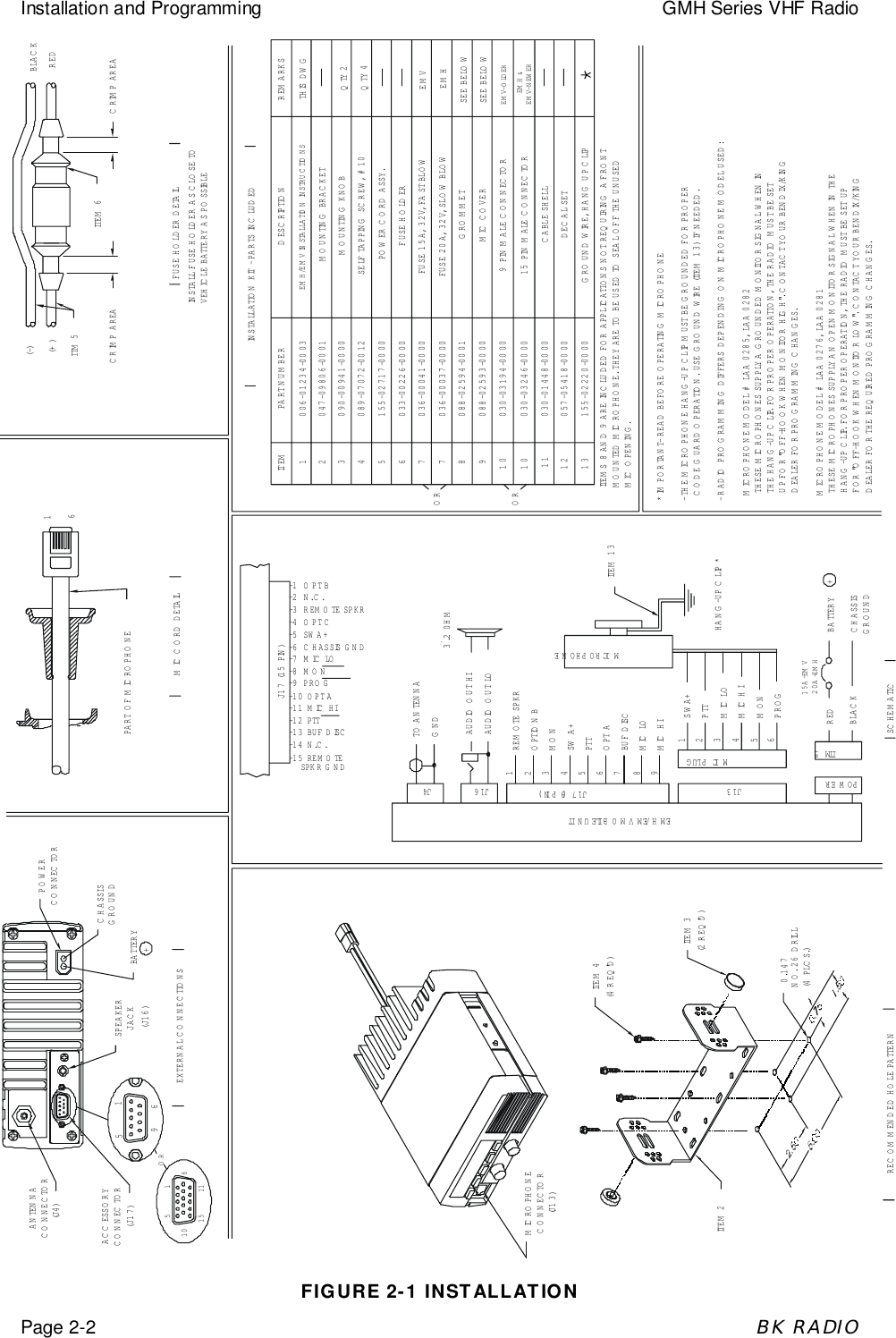
![GMH Series VHF Radio Installation and ProgrammingBK RADIOPage 2-54c. The existing ID number can be incremented onedigit by pressing the [PRI] key on the microphone.4d. Press the [ENT] key to store the new ID number andadvance to the next section.](https://usermanual.wiki/BK-Technologies/GMH599.Manual-Section-2/User-Guide-101842-Page-5.png)
![Installation and Programming GMH Series VHF RadioPage 2-6BK RADIO2.2.2.2 Transmitter Time Out TimerAfter the ID number is set, the display annunciatorwill indicate PRG TX. This is the duration of thetransmitter Time Out Timer. 0 SEC means the TimeOut Timer is disabled.Press the [PRI] key to increase the Time Out Timerduration by 15 seconds, with a maximum of 225seconds (3 minutes, 45 seconds). Press the [PRI]key again to change the duration from 225 secondsto zero.Press the [CLR] key to set the Time Out Timerduration to zero.Press the [ENT] key to store the changed settingand advance to the next section.Press the [FCN] key to advance to the next section ifno change is needed.2.2.2.3 Scan Delay TimeAfter the Time Out Timer is set, the upper displaywill indicate PRG SCN. This is the scan delay time inseconds.Press the [PRI] key to increase the scan delay timeby .5 seconds, up to 7.5 seconds. Press the [PRI]key again to change the time from 7.5 seconds to 0.Press the [CLR] key to reset the scan delay time to0.Press the [ENT] key to store the changed settingand advance to the next section.Press the [FCN] key to advance to the next section ifno change is needed.2.2.3 Channel 0 Group One FunctionsAfter the scan delay time is set the display will showPRG 1-12345. This is a group of five individualfunctions that can be enabled or disabled.When a function is enabled, the correspondingnumber in the display will flash. When the function isdisabled the number is steady. If you wish tochange the function from enable to disable or viceversa, press the number key corresponding to thatfunction.EXAMPLE: If function 4 (Priority Key Lockout) is disabled,the 4 in the display will not be flashing. If the [4] keyis pressed, the 4 in the display will f'lash, signifyingthat Priority Key Lockout is enabled. A subsequentpress of the [4] key wiIl disable Priority Key Lockout](https://usermanual.wiki/BK-Technologies/GMH599.Manual-Section-2/User-Guide-101842-Page-6.png)
![GMH Series VHF Radio Installation and ProgrammingBK RADIOPage 2-72.2.3.1 Priority ScanFunctions 2 and 3 are used to define Priority Scanoperation. There are three types of Priority Scanavailable. They are described in greater detail under"Priority Scan" beginning on page 3-8. Priority Scanmodes include:Priority Mode A - The Priority Channel follows theposition of the Channel Selector knob.Priority Mode B - The Priority Channel is fixed. Youwill transmit on the channel selected by the ChannelSelector knob.Priority Mode C - The Priority Channel is fixed.When the PRI toggle switch is on, you will transmiton the Priority Channel regardless of the ChannelSelector knob setting.To set Function 2 and 3 for Priority Mode A, B, or C, use the following chart:FUNCTION 2 FUNCTION 3PRIORITY MODE APRIORITY MODE BPRIORITY MODE CDISABLE (STEADY)ENABLE (FLASHING)ENABLE (FLASHING)DISABLE (STEADY)DISABLE (STEADY)ENABLE (FLASHING)2.2.3.2 PRI Key LockoutWhen function 4 is enabled (flashing) the [PRI] keyis locked out in the operating mode. The user will notbe able to change the designation of the PriorityChannel.When function 4 is disabled (steady) the user will beable to change the channei that is designated asPriority Channel. See "User Selected PriorityChannel" on page 3-7.2.2.3.3 Scan List LockoutWhen function 5 is enabled (flashing), the user willnot be able to change the channels in the scan list.When disabled (steady), the user can enter or deletechannels from the scan list. See "User SelectedScan List" on page 3-7.2.2.3.4 Store Group One SettingsOnce each function 1-5 is set as desired, you can store the changes, discard the changes, ordisable all 5 functions.Press the [CLR] key on the microphone to disable all Group One functions (steady).Press the [ENT] key to store new Group One settings into memory and advance to the nextsection.Press the [FCN] key to advance to the next section without saving changes.](https://usermanual.wiki/BK-Technologies/GMH599.Manual-Section-2/User-Guide-101842-Page-7.png)
![GMH Series VHF Radio Installation and ProgrammingBK RADIOPage 2-92.2.4.3 ANI EnableWhen function 4 is enabled (flashing) the ANI IDnumber will be transmitted (as a DTMF tonesequence) with each press of the PTT switch. See"Automatic Number Identification (ANI)N on page 2-4 for instructions on setting the ANI number.When functions 4 and 5 are both enabled (flashing)the ANI tone sequence will be transmitted only afterthe [ENT] key is pressed while the transmit PTTswitch is activated. A sidetone of the ANI numbertransmitted will also be heard through the speaker.2.2.4.4 DTMF EnableWhen function 5 is enabled (flashing) themicrophone keyboard becomes active for manualDTMF operation.2.2.4.5 Store Group Two SettingsOnce Group Two functions are set, press the [ENT] key to store them into memory andautomatically advance the program to the next section.Once each function 1-5 is set as desired, you can store the changes, discard the changes, ordisable all 5 functions.Press the [CLR] key to disable all Group Two functions (steady).Press the [ENT] key to store new Group Two settings into memory and advance to the nextsection.Press the [FCN] key to advance to the next section without saving changes.](https://usermanual.wiki/BK-Technologies/GMH599.Manual-Section-2/User-Guide-101842-Page-9.png)
![Installation and Programming GMH Series VHF RadioPage 2-10BK RADIO2.2.5 Alphanumeric Display Functions2.2.5.1 Group LabelThe GMH radio can be programmed to enable the display of alphanumeric labels. This canbe enabled only by using a computer, GMH Editor software, and an RS-232 interface cable:After Group Two functions, the display shows thecurrent label for the channel group, if alphanumericlabels are enabled. Each channel group can have alabel of up to eight characters or spaces. Thecharacters can include A - Z, 0 - 9, punctuationmarks, or a blank.• If no change is needed, press the [FCN] key to goback to the starting point for Channel 0 settings.• Press the [CLR] key to erase the current label.• Press the [CLR] key a second time to restore thecurrent label.2.2.5.2 Label With Numbers1 Press the [CLR] key. The display becomes blank.2. Press number keys to enter 0 - 9 in positions onethrough eight. The digits start in position eight, thenmove left.3. Use the following steps to enter a number in positioneight, or characters in positions one through eight:2.2.5.3 Label With Letters, Numbers, Etc.1. Press the [PRI] key repeatedly to cycle through theavailable characters: A - Z, 0 - 9,/ I ^ -! "# $ % & < >* + _ \ ( = ) ? then back to the start again (blank).If you pass the desired character, press the [PRI]key repeatedly until you return to the start and reachthat character again.2. Press the [FCN] key to shift the display left by oneposition, leaving position eight blank.3. Press the [PRI] key repeatedly to enter the nextcharacter, or press the [FCN] key a second time toenter a blank space.4. To abandon changes, press the [CLR] key, restoringthe original label.5. Press the [ENT] key to store changes and go backto the starting point for Channel 0 settings.2.2.6 Review Channel 0 ValuesPress the [FCN] key repeatedly to display eachvalue in Channel 0, then return to the Channel 0starting point.](https://usermanual.wiki/BK-Technologies/GMH599.Manual-Section-2/User-Guide-101842-Page-10.png)
![GMH Series VHF Radio Installation and ProgrammingBK RADIOPage 2-112.2.7 Enter Channel Frequencies and Code Guard ValuesAt the starting point for Channel 0, the displayshows PRG Ch 000. At this point, a channel numbercan now be pressed to allow access to thefrequency and Code Guard values for that channel.NOTE: A valid receive frequency must beprogrammed into each channel intended foruse. If a 0 value or an invalid frequency isprogrammed, the display will give a falsereading in the operation mode, and mayresult in radio malfunction. If a malfunctionoccurs, reset the radio by turning it off andthen back on.1. Press 1 and the display will show PRG Ch 001. Thisis the starting point for entering channel 1 values.2. Press the [FCN] key and the upper part of the displaywill show PRG RX. This is the receive frequency forchannel 1 (in MHz).3. If the displayed frequency is correct, press the [FCN]key to advance to the next value.If a new frequency is desired, press the [CLR] keyfollowed by the digits of the desired frequency. Thenpress the [ENT] key to store this frequency andautomatically advance to the next value.4. After the receive frequency is set, the upper part ofthe display will show PRG RX CG. This is the CodeGuard value for Channel 1 receive.NOTE: 0.0 indicates carrier squelch operation (noCode Guard).If the displayed value is correct, press the [FCN] keyto advance to the next value.If a new value is desired, press the [CLR] key toreset the display to 0.0. Press the number keys 0thru 9 to enter a Tone Code Guard value. See"Tone Code Guard Values" on page 2-14.To enter a Digital Code Guard value press the [#]key, causing the letter D to appear followed by threezeros. Enter the desired digital code using keys 0thru 7 (keys 5 & 9 do not respond). See "DigitalCode Guard Values" on page 2-14. Pressing the[PRI] key after the three-digit code has beenentered allows the digital code to be inverted. Whenthe displayed value is correct, press the [ENT] keyto store the Code Guard value and automaticallyadvance to the next value.5. After the receive Code Guard is set, the upper part ofthe display will show PRG TX. This is thetransmitter frequency for Channel 1. If it is correct,press the [FCN] key to advance to the next value.](https://usermanual.wiki/BK-Technologies/GMH599.Manual-Section-2/User-Guide-101842-Page-11.png)
![Installation and Programming GMH Series VHF RadioPage 2-12BK RADIOIf you wish to change it, press the [CLRJ keyfollowed by the frequency in MHz then [ENT] tostore the new frequency and automatically advanceto the next value.Only valid frequencies will be operable.6. After the transmit frequency is set the upper part ofthe display will show PRG TX CG. This is the CodeGuard value for Channel 1 transmit (0.0 indicatescarrier squelch). If this value is correct press the[FCN] key to advance to the next value. To enter anew value, press the [CLR] key to reset the displayto 0.0. Press the number keys to enter a Tone CodeGuard value. See "Tone Code Guard Values" onpage 2-14.To enter Digital Code Guard, first press the [CLR]key, then the [#] key, causing the letter D to appearfollowed by three zeros. Enter the desired digitalcode using keys 0 thru 7 (keys 8 & 9 do notrespond). See 'Digital Code Guard Values" on page2-14. Pressing the [PRI] key after the three digitcode has been entered allows the digital code to beinverted. When the displayed value is correct, pressthe [ENT] key to store the Code Guard andautomatically advance to the next value.7. After the transmit Code Guard is set, the display willshow the channel label. If this label is correct pressthe [FCN] key to proceed to the entry point.If a new channel label is desired, follow theinstructions under "Group Label" on page 2-9.8. After the channel label is set, the display will return tothe Channel 1 starting point. If you wish to reviewthe frequencies and Code Guard values in Channel1, subsequent pressing of the [FCN] key will showeach value and then return to the Channel 1 startingpoint.9. At the starting point for Channel 1, the display willshow PRG Ch 001. Press the number keys foranother channel number to gain access to thefrequencies and Code Guard values for thatchannel. Each channel is then programmed usingthe same steps described for Channel 1.2.2.8 Leave Programming Mode1. Rotate the OFF-VOL knob counterclockwise to theOff position.2. The radio will be in normal operation mode the nexttime it is turned on.](https://usermanual.wiki/BK-Technologies/GMH599.Manual-Section-2/User-Guide-101842-Page-12.png)
![GMH Series VHF Radio Installation and ProgrammingBK RADIOPage 2-132.3 CLONING RADIO SETTINGSA portable radio with a keyboard and display can transfer its programmed settings to an GMH radioby using a cloning cable. A radio cannot transfer Alphanumeric display settings, including channellabels and group labels.Both units must be of the same frequency band. Settings for any group in a portable radio can bedownloaded to any group in the GMH radio. The GMH radio must be programmed with groups of 14channels. Cloning can only be accomplished group by group. To perform group cloning:1. With the portable radio in normal operation mode,press the [#] key followed by number keys to selectthe group to be downloaded.2. Set the GMH radio to the group that is to receive thedownload, using the same method as in step 1, orby pressingthe GRP button and turning the ChannelSelect knob.3. Connect the Master end of the cloning cable into themicrophone connector of the portable radio. This isthe cable end with the pushbutton Master switch.4 Put the portable radio into programming mode byholding down the Master switch and pressing the[FCN] key until the display shows ---ID.5. Enter the correct Password Code.6. Press the [FCN] key repeatedly to review the valuesin Channel 0. Make any required changes at thistime.7. Attach the other end of the cloning cable into themicrophone connector of the EM H radio to becloned.8. Press the [*] key on the portable radio. The displaywill flash PROG, signifying that the radio is ready todownload.9. Press the [FCNJ key. The program in the portablewill download to the GMH. The GMH will send backthe program to the portable to verify successfulcloning.10. If the download was successful, the portable radiowill resume flashing PROG. Turn off the GMH radio.Disconnect the cable. Normal radio operation willoccur the next time the GMH radio is turned on.11. If the download was not successful the portableradio will flash FAIL, followed by continuous beeps.Failure to download the portable program can bedue to:A. Incorrect radio types.B. Improper connection.C. Failure to power up radio.NOTE: To stop FAIL mode, press the [CLR] key,turn off the radios, and start again at Step 1.](https://usermanual.wiki/BK-Technologies/GMH599.Manual-Section-2/User-Guide-101842-Page-13.png)
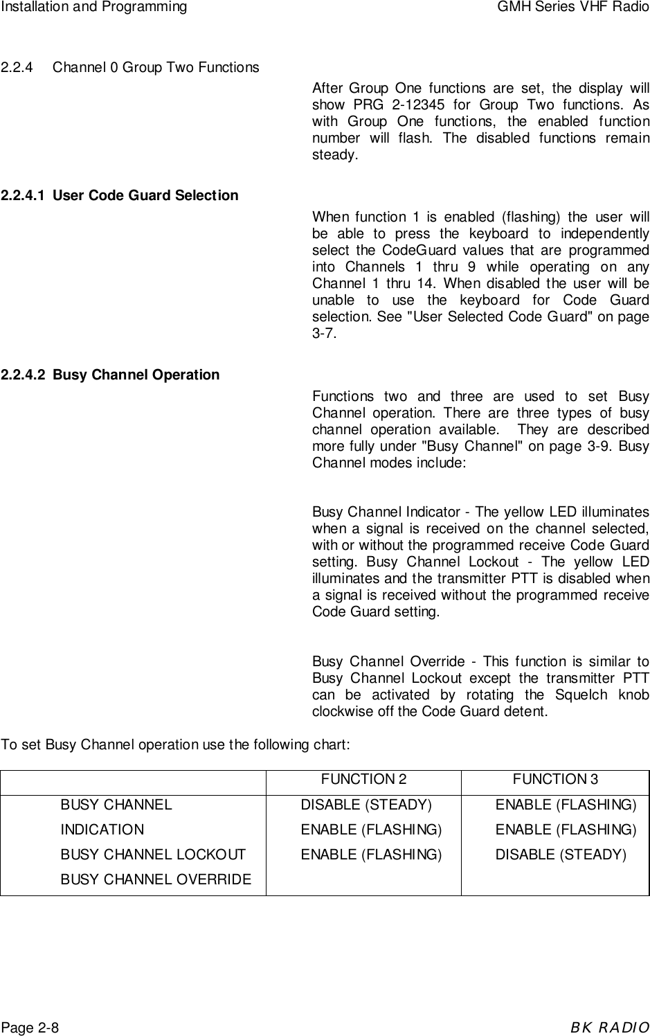
![Installation and Programming GMH Series VHF RadioPage 2-14BK RADIO2.3.1 Special Cloning InstructionsIt is possible to change Channel 0 values on the portable radio, hold them in a temporary memory,and download them to the GMH without actually entering them into the permanent memory of theportable radio. This is convenient for sequential identification numbers used to identify a series ofportables in a radio system. Assuming that the frequencies, Code Guard values, and other Ch 0values are common for all radios in the system, but that the radio identification number should beunique to each radio, the following method would be used to clone additional radios for the system.1. Program the portable radio with all frequencies,Code Guard values, and Channel 0 values that willbe common to all GMH radios to be cloned.2. Advance the display to show the portable radio's IDnumber-for example, 100.3. Press the [CLR] key; press 125. Do not press the[ENT] key. Now 125 is in temporary memory.4. Press the [*] key, connect the cable to the radiosand download to the GMH by pressing the [FCN]key. ID number 125 is now stored in permanentmemory of the GMH.5. After download, press the [CLR] key on the portableradio. Disconnect the GMH. The portable radiodisplay will show that 125 is still being held in thetemporary memory of the portable radio.6. Press the [PRI] key. This will increment the IDnumber one digit to 126. (Note: any new number canbe entered at this point by pressing the [CLR] keyand using the digit keys to enter the new number.)7. Press the [*] key. Connect the cable to the secondGMH and download by pressing [FCN].8. Any number of radios can be coded with different orsequential ID numbers using this technique. The IDnumber in the permanent memory of the portableradio will remain unchanged as 100.2.3.2 Scan List and Priority Channel CloningWhen a portable radio downloads to an GMH, theScan List and Priority Channel designations are alsotransferred to the GMH. This includes Priority Modeand any lockout functions.To program an GMH with a specific Priority Mode,Priority Channel, and Scan List along with therespective lockout functions (if desired), the portableradio must first be programmed with theseparameters. The lockout functions cannot be held intemporary memory. See the appropriate operatingprocedures in Section 3 for selecting the Scan List,Priority Channel, and Lockout functions. See"Priority Scan" on page 2-6 for Priority Modeselection procedures.](https://usermanual.wiki/BK-Technologies/GMH599.Manual-Section-2/User-Guide-101842-Page-14.png)