BMC Medical YH600AYH600B Portable Diagnostic System User Manual
BMC Medical Co., Ltd. Portable Diagnostic System Users Manual
UserManual.wiki
>
BMC Medical
>
YH600AYH600B User Manual
Users Manual
Navigation menu
Upload a User Manual
Namespaces
Wiki Guide
HTML
PDF
Info
Views
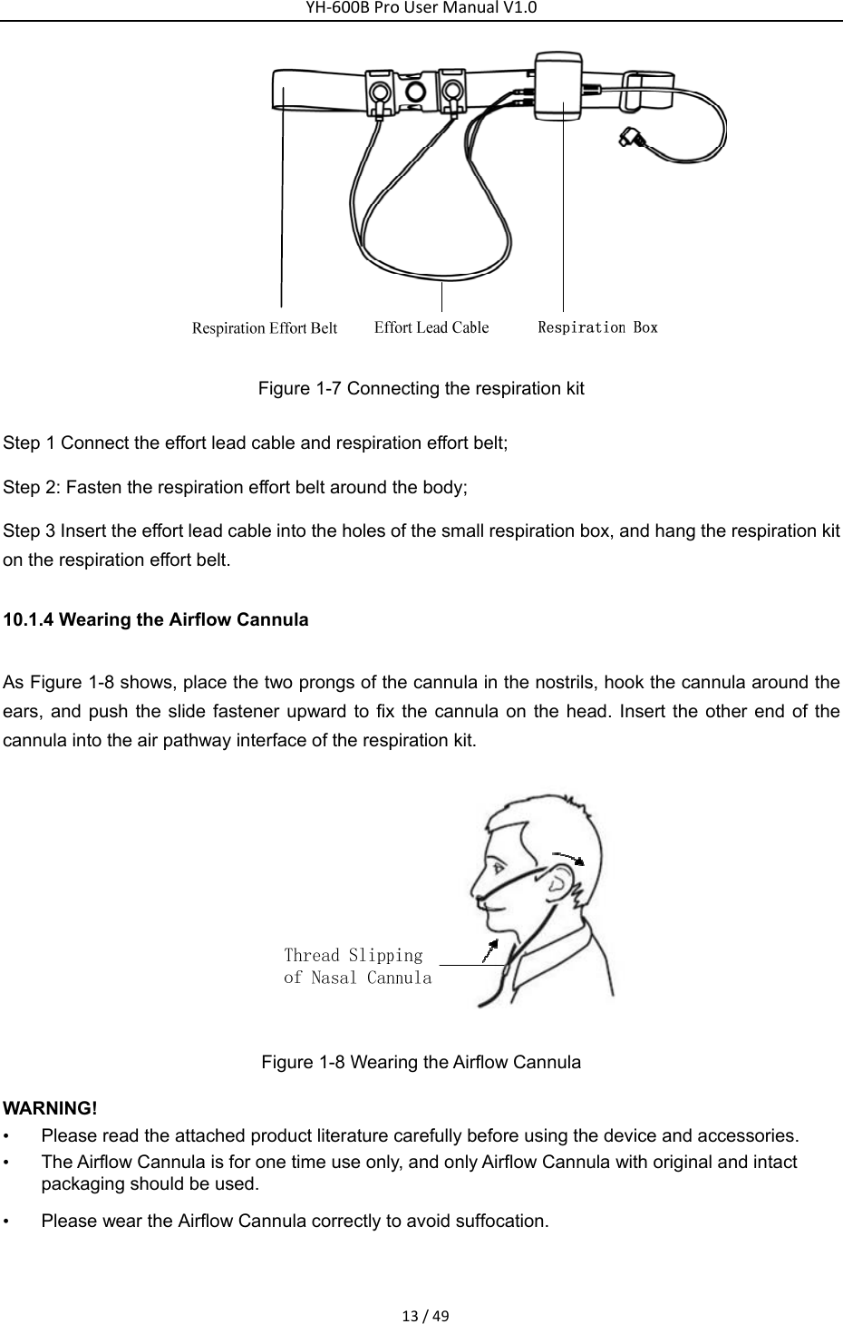
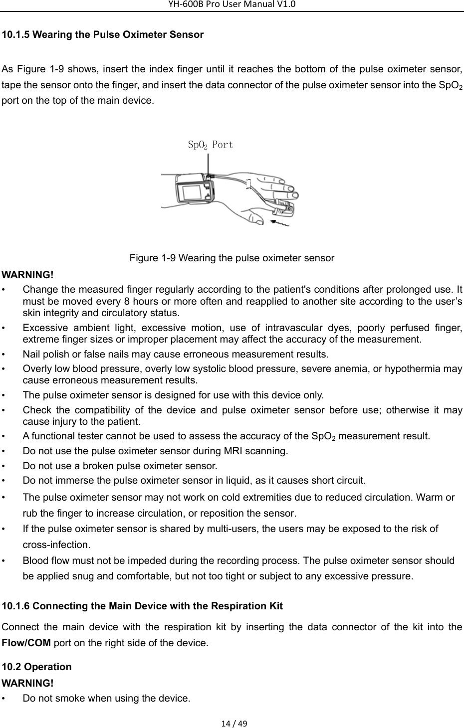
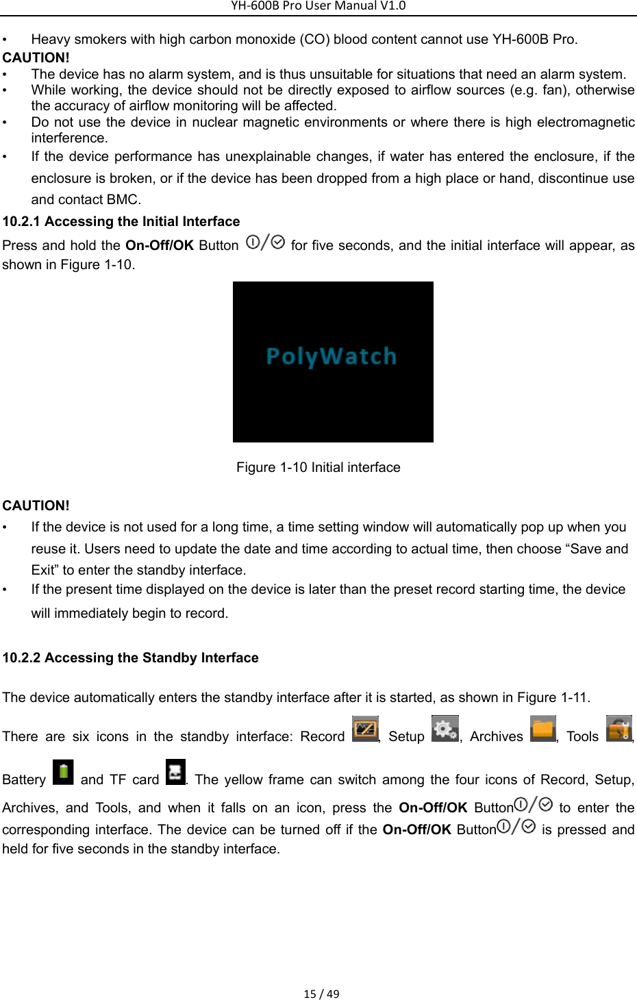
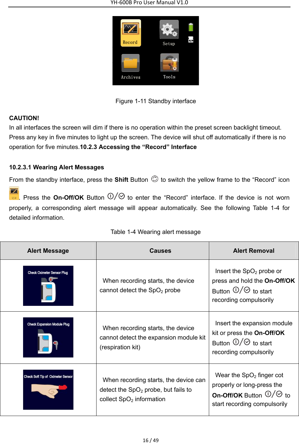
User Manual
Discussion / Help
Navigation