BMC Medical YH600AYH600B Portable Diagnostic System User Manual
BMC Medical Co., Ltd. Portable Diagnostic System Users Manual
Users Manual

Portable Diagnostic System
YH-600B Pro
User Manual

YH‐600BProUserManualV1.0
Table of Contents
CHAPTER 1: DEVICE INTRODUCTION AND OPERATION ................................................................ 1
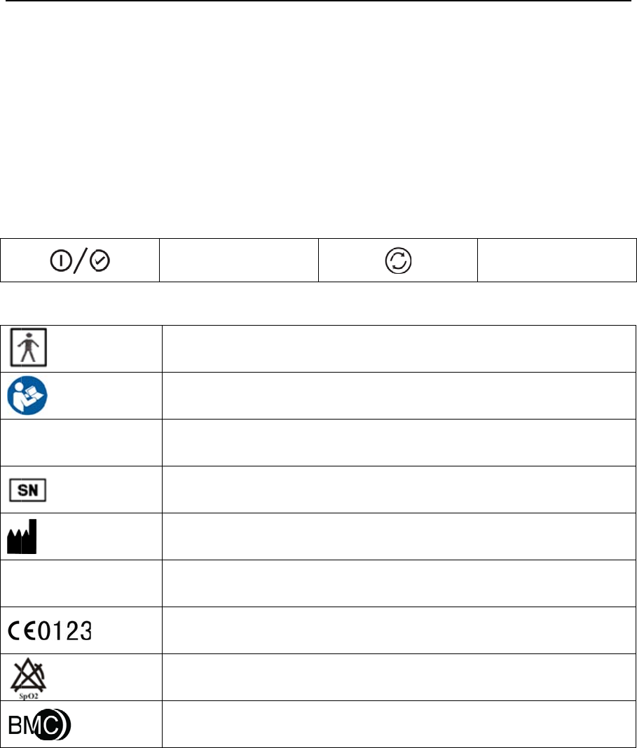
1. Symbols .............................................................................................................................................. 1
1.1 Control Buttons .......................................................................................................................... 1
1.2 Device Symbols ......................................................................................................................... 1
2. Warnings, Cautions and Important Tips ............................................................................................. 1
3. Contraindications ................................................................................................................................ 2
4. Specifications...................................................................................................................................... 2
5. Intended Use ...................................................................................................................................... 4
6. Glossary .............................................................................................................................................. 5
7. Model .................................................................................................................................................. 6
8. Package Contents .............................................................................................................................. 7
9. System Features ................................................................................................................................ 8
9.1 General Introduction .................................................................................................................. 8
9.2 Main Device Structure ............................................................................................................... 8
10. Instructions for Use ........................................................................................................................... 9
10.1 Setting up and Wearing the Device ...................................................................................... 10
10.1.1 Installing the TF Card and Battery ..................................................................... 10
10.1.2 Wearing the Main Device ................................................................................... 12
10.1.3 Connecting the Respiration Kit .......................................................................... 12
10.1.4 Wearing the Airflow Cannula .............................................................................. 13
10.1.5 Wearing the Pulse Oximeter Sensor ................................................................. 14

YH‐600BProUserManualV1.0
10.1.6 Connecting the Main Device with the Respiration Kit ........................................ 14
10.2 Operation ............................................................................................................................... 14
10.2.1 Accessing the Initial Interface ............................................................................ 15
10.2.2 Accessing the Standby Interface ....................................................................... 15
10.2.3 Accessing the “Record” Interface ....................................................................... 16
10.2.4 Accessing the “Setup” Interface ......................................................................... 18
10.2.5 Accessing the “Archives” Interface .................................................................... 19
10.2.6 Accessing the “Tools” Interface .......................................................................... 20
10.2.7 Turning Off the Device ....................................................................................... 22
11. Troubleshooting .............................................................................................................................. 23
12. Cleaning and Disinfection ............................................................................................................... 24
12.1 Cleaning ................................................................................................................................ 24
12.2 Disinfection ............................................................................................................................ 25
13. Disposal .......................................................................................................................................... 26
14. EMC Requirements ........................................................................................................................ 27
CHAPTER 2: POLYLOGIC SLEEP ANALYSIS SOFTWARE .............................................................. 30
1. Installation ......................................................................................................................................... 30
1.1 Software Installation ................................................................................................................ 30
1.2 Driver Installation..................................................................................................................... 30
2. Patient Information Setup ................................................................................................................. 30
3. Data Reception ................................................................................................................................. 32
3.1 Run Software ........................................................................................................................... 32

YH‐600BProUserManualV1.0
3.2 Connection of YH-600B Pro and Computer ............................................................................ 32
3.3 Data Transmission .................................................................................................................. 33
3.3.1 TF Card Data Transmission ................................................................................. 35
3.3.2 Bluetooth Data Transmission ............................................................................... 35
4. Data File Management ..................................................................................................................... 39
5. Data Playback .................................................................................................................................. 40
5.1 Opening and Closing the Data File ......................................................................................... 40
5.2 Display of Recorded Data and Analysis Result ...................................................................... 40
6. Print Preview and Output ................................................................................................................. 47
7. Help................................................................................................................................................... 48
8. Exit Program ..................................................................................................................................... 48
CHAPTER 3: SERVICE ........................................................................................................................ 49
1. Technical Support ............................................................................................................................. 49
2. Limited Warranty ............................................................................................................................... 49
C
H
T
h
of
im
I
m
th
e
1.
1.
1
1.
2
IP
2
2
.
W
A
In
d
C
A
In
d
I
M
Pl
a
W
a
H
APTER 1:
D
h
e informatio
n
continued p
r
provements
m
ages shown
e
actual pro
d
Symbols
1
Control B
u
2
Device S
ym
2
2
Warnin
g
s,
C
A
RNING!
d
icate the p
o
A
UTION!
d
icate the p
o
M
PORTANT
T
a
ce emphas
i
a
rnings, Ca
u
D
EVICE INT
n
in this man
r
oduct devel
o
to this man
u
here are in
d
d
uct shall go
v
u
ttons
mbols
T
A
C
autions a
n
o
ssibility of in
j
o
ssibility of d
a
T
IP!
i
s on an ope
r
u
tions, and I
m
Y
H
RODUCTIO
N
ual has bee
n
o
pment, BM
C
u
al and the p
r
d
icative only.
v
ern.
On-Off/O
K
T
ype BF Ap
p
Follow Instr
u
≥ 12.5 mm
D
Serial Numb
Manufactur
e
A
uthorized
R
European U
n
No SpO
2
A
l
a
Logo of BM
C
n
d Importan
t
j
ury to the u
s
a
mage to th
e
r
ating chara
c
m
portant Tip
s
H
‐600BProUs
1
/
N
AND OPE
n
carefully c
h
C
Medical C
o
r
oducts it de
s
If there is in
K
Button
p
lied Part
u
ctions for U
s
D
iameter, Dri
p
er of the Pr
o
er
R
epresentati
v
n
ion Approv
a
a
rms
C
Medical C
o
t
Tips
s
er or operat
e
device.
c
teristic.
s
appear thr
o
erManualV1
/
49
RATION
h
ecked and i
s
o
., Ltd. reser
v
s
cribes at an
consistency
s
e
p
ping (15ºtilt
e
o
duct
v
e in the Eur
o
a
l
o
., Ltd.
t
or.
o
ughout this
m
.0
s
believed to
v
es the right
y time, with
o
between the
e
d)
o
pean Com
m
m
anual as t
h
be accurate
.
to make ch
a
o
ut notice or
o
image and
a
Shi
f
m
unity
h
ey apply.
.
In the inter
e
a
nges and
o
bligation.
a
ctual produ
c
f
t Button
e
st
c
t,

YH‐600BProUserManualV1.0
2/49
3. Contraindications
Depending on the skin condition or general state of health, the patient may experience sensitivity to the
wrist belt or the self-adhesive pulse oximeter sensor. Discontinue use if an allergic reaction to the
skin-contact materials occurs.
4. Specifications
SpO2
Range
Accuracy
0%~100%
≤±3%(70%~85%),≤±2%(85%~100%)
≤±3% (70%~85%), ≤±2% (85%~100%)
Pulse rate
Range
Accuracy
30~250 bpm
≤2 bpm (30~100 bpm)
≤2% (100 bpm~250 bpm)
Wavelengths
Red 663 nanometers
Infrared 890 nanometers
Maximal Optical Output Power Less than 1.5mw maximum average
Airflow waveform
Frequency
Margin of error
10~40 times per minute
≤±1 time
CPAP pressure
Range
Margin of error
4~20 hPa
≤±1 hPa
Snore 150~300 Hz
Thorax/Abdomen effort
Range
Margin of error
10~40 times per minute
≤±3 times per minute
Body position Supine position, sleep on left or right side, and
prone positons can be detected
Wrist movement (sleep/awake) Automatic sleep-awake identification from wrist
movement
Temperature
Operation
Storage/Transportation
5°C~35°C
-20°C~55°C
Humidit
y
Operation
Storage/Transportation
≤80% (non-condensing)
≤93% (non-condensing)

YH‐600BProUserManualV1.0
3/49
Atmospheric pressure
Operation
Storage/Transportation
860~1,060 hPa
700~1,060 hPa
Power supply DC 1.5 V ±0.15 V(1×1.5 V R6 AA)
Minimum record duration No less than 8 hours
Data storage 64 records can be stored on TF card
Dimensions 78 mm × 60 mm × 21 mm (main device)
Weight 75 g (main device without battery)
Type of protection against electrical shocks Internal power supply
Classification of protection against
electrical shocks
Type BF applied part
Waterproof rating IP22
Working mode Continuous operation

YH‐600BProUserManualV1.0
4/49
5. Intended Use
YH-600B Pro records the following data: patient respiratory nasal airflow, snoring, blood oxygen
saturation, pulse, respiratory effort, body position and wrist movement during sleep. It can also be
connected to a CPAP system to record and display continuous positive airway pressure. The device
uses these recordings to produce a report that may aid in the diagnosis of sleep-disordered breathing or
for further clinical investigation. The device is intended for the hospital/institutional environment
(supervised) and the home environment (unsupervised) for adults.
WARNING!
• When using consumables and accessories, please read the manufacturer’s information supplied
with the products.
• This device is intended for adult use only. Do not use the device on infant or neonatal patients.
• Do not use the device in situations where alarms are required. The device has no audible alarms.
• Keep all parts away from children.
• YH-600B Pro and its accessories are for the specified intended use only.
• Do not smoke while wearing YH-600B Pro.
• Risk of explosion. Never use the device in the vicinity of flammable gases (e.g. anesthetics).
• No modification of this equipment is allowed.
CAUTION!
• Heavy smokers with a high level of carbon monoxide (CO) in blood cannot use YH-600B Pro.
• YH-600B Pro cannot be used on a water bed or a bed with an electric blanket, because these
electrical equipment will disturb the operation of YH-600B Pro.
• Federal law restricts these devices to sale by or on the order of a physician.
• YH-600B Pro meets requirements of electromagnetic compatibility. If you doubt YH-600B Pro may
disturb the operation of other electrical equipments, such as televisions, radios and mobile phones,
or if YH-600B Pro does disturb the operation, you should move YH-600B Pro far away from these
equipment.
• YH-600B Pro must be able to measure the pulse properly to obtain accurate SpO2 measurement.
Make sure that nothing is hindering the pulse measurement before relying on the SpO2
measurement.
• YH-600B Pro measures the percentage of arterial oxygen saturation of functional hemoglobin.
Significant levels of dysfunctional hemoglobin such as carboxyhemoglobin or methemoglobin may
affect the accuracy of the measurement.
• FCC Caution: Any changes or modifications not expressly approved by the party responsible for
compliance could void the user’s authority to operate this device.

YH‐600BProUserManualV1.0
5/49
6. Glossary
Snore Because of the respiratory tract’s airway limitation, sound is made
when respiratory airflow gets through the narrow respiratory tract,
which usually indicates that the patient is likely to have suffered in
years from sleep apnea syndrome along with the increase of age.
Apnea The performance of respiratory intermission during sleep is that the
respiratory airflow drops to lower than 10% of the normal range and
lasts for at least 10 seconds. The recurrent intermission during
sleep is easy to cause severe oxygen-deficit to brain and blood,
form hypoxemia and induce hypertension, brain-heart disease,
arrhythmia, myocardial infarction and angina, which then can induce
multi-system diseases of the human body.
Hypopnea The reduction range of respiratory airflow is more than 50% of the
normal, accompanied with more than 4% of oxyhemoglobin
saturation reduction.
SAHS The SAHS means at least 30 times of apnea in 7 hours of nightly
sleep time of adults and each apnea lasts for more than 10 seconds.
Or the apnea hypopnea index AHI (the number of apneas and
hypopneas per hour) is greater than 5.
OASHS The OSAHS means the sleep apnea hypopnea syndrome caused by
obstruction of the upper respiratory tract (including the collapse of
pharyngeal mucosa).
AI The AI means the number of apneas per hour, which is equal to the
number of times apnea has occurred the whole night divided by the
sleep time of whole night (awakening and invalid time are not
contained). The unit of time is hour.
HI The HI means the number of hypopneas per hour, which is equal to
the number of times hypopnea has occurred the whole night divided
by the sleep time of whole night (awakening and invalid time are not
contained). The unit of time is hour.
AHI The AHI means the number of apneas and hypopneas per hour
which is equal to the total times of apneas and hypopneas during
the whole night divided by the sleep time of whole night (awakening
and invalid time are not contained),and the unit of time is hour.
SNI The SNI means the average number of times the snore has occurred
every hour which is equal to the number of times snore has occurred
the whole night divided by the sleep time of whole night (awakening
and invalid time are not contained). The unit of time is hour.
ODI The ODI means the number of times when the oxyhemoglobin
saturation reduction is more than 3% or 4% every hour.
CPAP The CPAP means feeding continuous positive airflow into air
passage by face mask.

YH‐600BProUserManualV1.0
6/49
7. Model
Table 1-1 Monitoring Parameters and Components
Model Monitoring Parameters Components
YH-600B
Pro
SpO2, pulse rate, airflow
waveform, thorax/abdomen
effort, body position, snore, wrist
movement (sleep/wake), CPAP
pressure
Main Device, Respiration Kit, Respiration
Effort Belt, Effort Lead Cable, USB Data
Cable and Bluetooth Data Transmission, TF
Card, Pulse Oximeter Sensor, CPAP
Pressure Tube, Airflow Cannula, Wrist Belt,
Computer Software
YH‐600BProUserManualV1.0
7/49
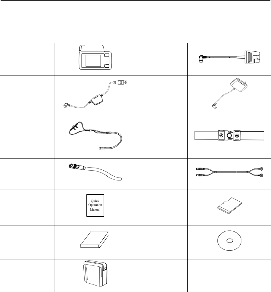
8. Package Contents
Table 1-2 shows package contents.
Table 1-2 Package Contents
Main Device
Pulse
Oximeter
Sensor
USB Data
Cable
Respiration
Kit
Airflow
Cannula
Respiration
Effort Belt
CPAP
Pressure
Tube
Effort Lead
Cable
Quick
Operation
Manual
TF Card
User Manual
Computer
Software
Disk
Carrying
Case
All parts and accessories do not contain latex.
WARNING!
• This device should only be used with the tube and accessories manufactured or recommended by
BMC or with those recommended by your prescribing physician. The use of inappropriate tubes
and accessories may affect the performance of the device and impair monitoring effects.
CAUTION!
• The use of non-BMC-certified accessories may undermine system security, so it is recommended
that users only use the pulse oximeter sensor and other accessories provided by BMC.
• It is recommended to use Airflow Cannula with the registration certification for medical device.
• This device and its accessories are for intended use only.
① The belt on the main device is in accordance with the biological evaluation of medical devices.

YH‐600BProUserManualV1.0
8/49
② The finger sheath and cannula are CE marking approved, indicating compliance to the Medical
Device Directive.
③ Several accessories are available for using YH-600B Pro. To ensure a safe and effective therapy,
adopt only BMC accessories. All accessories do not contain latex.
9. System Features
9.1 General Introduction
The performance and functional characteristics of YH-600B Pro include all the user-friendly features of
the predicate device.
YH-600B Pro is powered by one 1.5 V AA battery. Testing was performed to demonstrate that the
performance of YH-600B Pro in its intended environment is as safe and effective as that of the legally
marketed predicate devices. The safety and effectiveness of YH-600B Pro have been verified through
performance-related testing that consisted of Electrical Safety, Electromagnetic Compatibility,
Mechanical and Environment Testing.
The recorded data, such as SpO2, pulse rate, airflow waveform, snore and CPAP pressure, can be
replayed on a computer via the PolyLogic Sleep Analysis Software which is provided with YH-600B Pro.
The device can be used as a standalone unit for recording data. It can also interact with a commercially
available IEC60950-1 compliant computer, which can be used to review data. The device does not have
any audible alarms, and, therefore, should not be used for continuous monitoring.
Patient is an intended operator, who can safely use all functions and can perform all maintenances
mentioned in the User Manual.
All parts of the device are applied parts.
9.2 Main Device Structure
Display Screen Shift Button
On-Off/OK Button
Flow/COM Port
SpO2Port
Figure 1-1 Main device structure

YH‐600BProUserManualV1.0
9/49
Table 1-3 shows Component and Function.
Table 1-3 Component and Function
Component Function
Display Screen Display the menu, alerts and data monitored
Shift Button Switch interfaces and options
On-Off/OK Button Turn on/off the device, and confirm adjustment
SpO2 Port Connect to the pulse oximeter sensor to collect data on SpO2 and
pulse rate
Flow/COM Port
Connect to the respiration kit to collect data on the airflow waveform
and snore; connect to the computer with a USB data cable to transfer
data.
10. Instructions for Use
CAUTION!
• Avoid exposure to sources of direct airflow such as fans during recording.
• Avoid using this device in an MRI environment or in close proximity to a high EMI emission source.
• Do not attempt to take the main device apart. No user-serviceable parts are inside.
• If any unexplained changes are noticed in the performance of this device, if the device is dropped
or mishandled, if water is spilled into the enclosure, or if the enclosure is broken, discontinue use
and contact BMC.
YH‐600BProUserManualV1.0
10/49
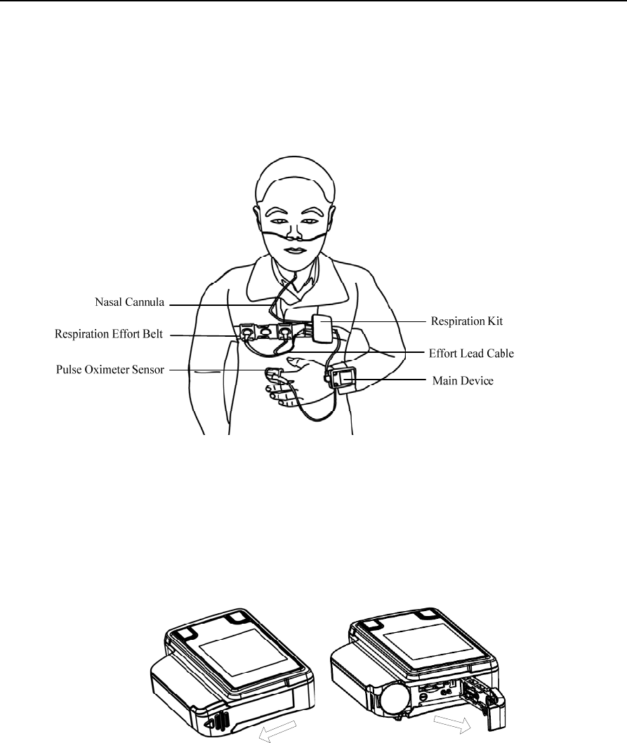
10.1 Setting up and Wearing the Device
Figure 1-2 shows a user wearing YH-600B Pro. See sections 10.1.1~10.1.6 for detailed wearing
instructions.
Figure 1-2 Wearing YH-600B Pro
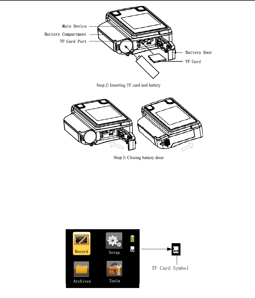
10.1.1 Installing the TF Card and Battery
Push and pull the battery door according to Step 1. Insert the TF card into the slot and put a new AA
battery with the positive and negative terminals on the correct sides according to Step 2. Close the
battery door according to Step 3 (Figure 1-3).
Step 1: Opening battery door
YH‐600BProUserManualV1.0
11/49
Figure 1-3 Inserting the TF card and battery
WARNING!
The battery may leak or explode if used or disposed of improperly.
When the TF card and battery are correctly inserted into the device, a symbol indicating correct
insertion of the TF card will appear in the standby interface, as shown in Figure 1-4.
Figure 1-4 Symbol indicating correct insertion of TF card
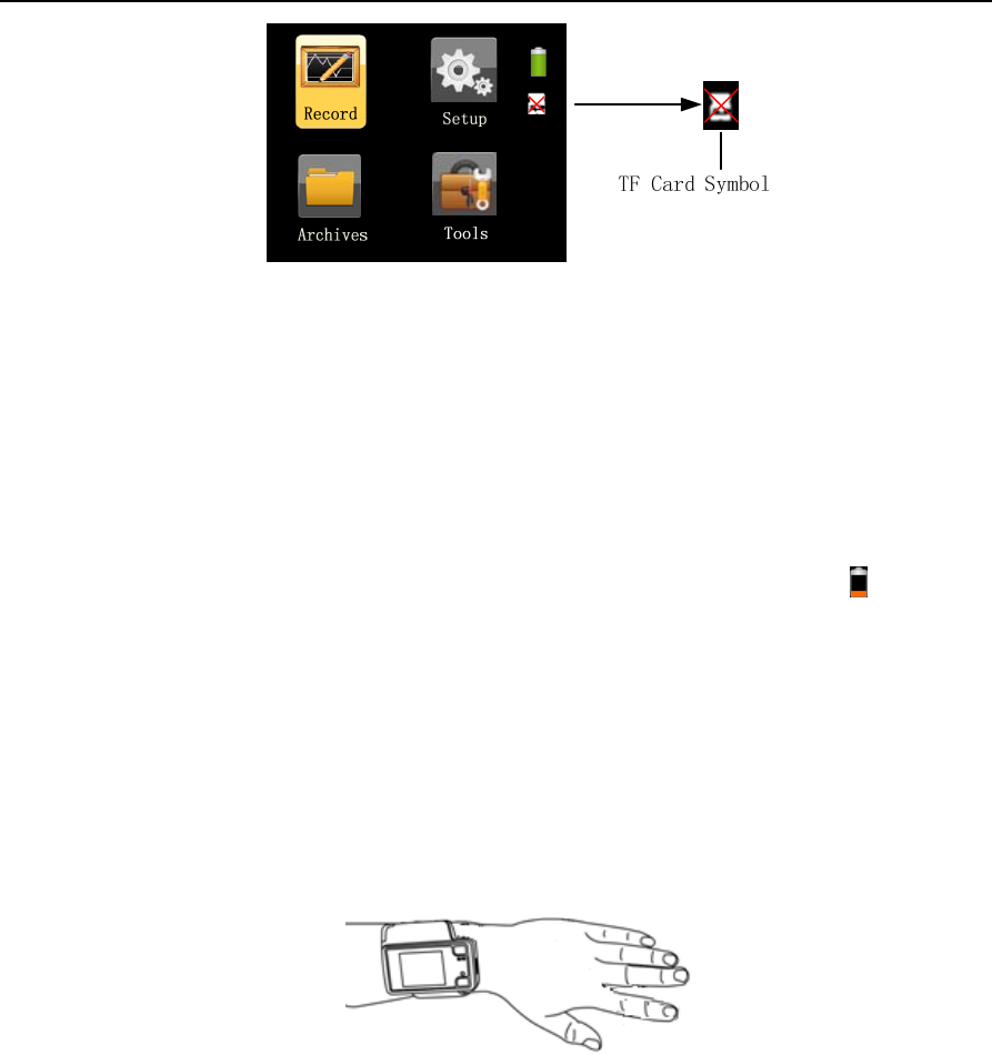
If the TF card is inserted incorrectly or not inserted, a red “X” symbol will appear on the “TF card” icon in
the standby interface, as shown in Figure1-5, indicating “incorrect insertion or absence of TF card”.
YH‐600BProUserManualV1.0
12/49
Figure 1-5 Symbol indicating incorrect insertion or absence of TF card
CAUTION!
• When there is a red “X” symbol on the “TF card” icon in the standby interface, the user should
check whether the TF card is inserted incorrectly or not inserted. If it is inserted correctly, the TF
card may be broken.
• Please place a fully charged or new AA battery every time before recording. Use only the specified
types of battery or rechargeable battery.
• Replace the battery when the battery quantity drops below 1.2 V, as the icon shows or when the
screen flickers.
• If the device has not been used for a long time, remove and put away the battery to prevent
electrolyte leakage from damaging the device.
10.1.2 Wearing the Main Device
Wear the main device on the wrist as a watch, and fasten the wrist belt when the device is properly
positioned, as shown in Figure 1-6.
Figure 1-6 Wearing the main device
CAUTION!
Make sure the wrist belt is neither too loose nor too tight; otherwise normal device operation will be
affected.
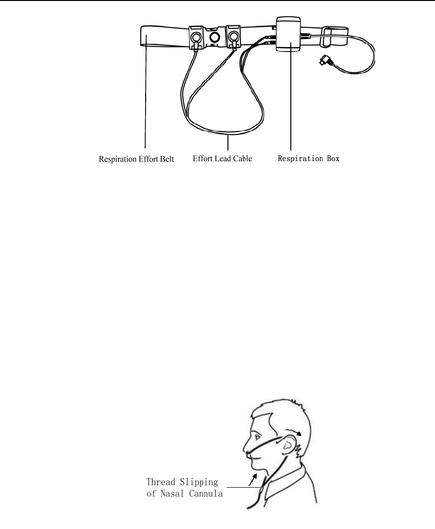
10.1.3 Connecting the Respiration Kit
Connect the respiration kit according to steps 1~3, as shown in Figure 1-7.
YH‐600BProUserManualV1.0
13/49
Figure 1-7 Connecting the respiration kit
Step 1 Connect the effort lead cable and respiration effort belt;
Step 2: Fasten the respiration effort belt around the body;
Step 3 Insert the effort lead cable into the holes of the small respiration box, and hang the respiration kit
on the respiration effort belt.
10.1.4 Wearing the Airflow Cannula
As Figure 1-8 shows, place the two prongs of the cannula in the nostrils, hook the cannula around the
ears, and push the slide fastener upward to fix the cannula on the head. Insert the other end of the
cannula into the air pathway interface of the respiration kit.
Figure 1-8 Wearing the Airflow Cannula
WARNING!
• Please read the attached product literature carefully before using the device and accessories.
• The Airflow Cannula is for one time use only, and only Airflow Cannula with original and intact
packaging should be used.
• Please wear the Airflow Cannula correctly to avoid suffocation.
YH‐600BProUserManualV1.0
14/49
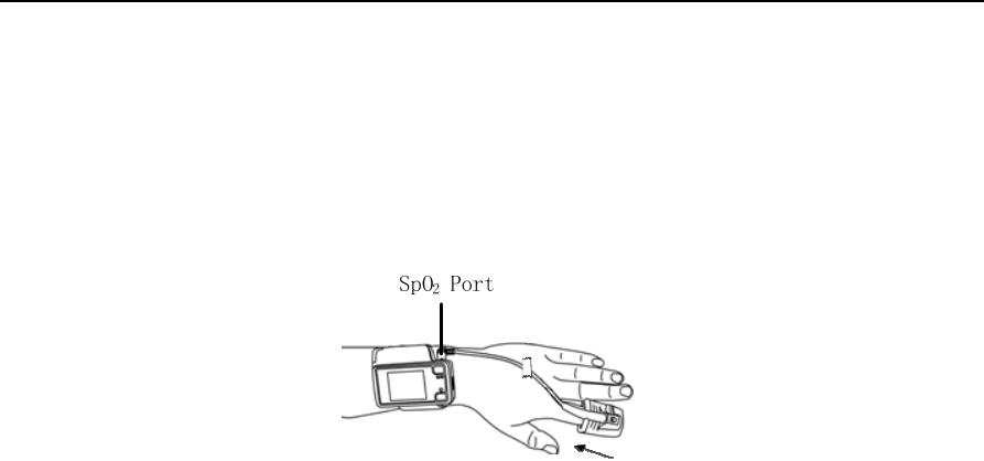
10.1.5 Wearing the Pulse Oximeter Sensor
As Figure 1-9 shows, insert the index finger until it reaches the bottom of the pulse oximeter sensor,
tape the sensor onto the finger, and insert the data connector of the pulse oximeter sensor into the SpO2
port on the top of the main device.
Figure 1-9 Wearing the pulse oximeter sensor
WARNING!
• Change the measured finger regularly according to the patient's conditions after prolonged use. It
must be moved every 8 hours or more often and reapplied to another site according to the user’s
skin integrity and circulatory status.
• Excessive ambient light, excessive motion, use of intravascular dyes, poorly perfused finger,
extreme finger sizes or improper placement may affect the accuracy of the measurement.
• Nail polish or false nails may cause erroneous measurement results.
• Overly low blood pressure, overly low systolic blood pressure, severe anemia, or hypothermia may
cause erroneous measurement results.
• The pulse oximeter sensor is designed for use with this device only.
• Check the compatibility of the device and pulse oximeter sensor before use; otherwise it may
cause injury to the patient.
• A functional tester cannot be used to assess the accuracy of the SpO2 measurement result.
• Do not use the pulse oximeter sensor during MRI scanning.
• Do not use a broken pulse oximeter sensor.
• Do not immerse the pulse oximeter sensor in liquid, as it causes short circuit.
• The pulse oximeter sensor may not work on cold extremities due to reduced circulation. Warm or
rub the finger to increase circulation, or reposition the sensor.
• If the pulse oximeter sensor is shared by multi-users, the users may be exposed to the risk of
cross-infection.
• Blood flow must not be impeded during the recording process. The pulse oximeter sensor should
be applied snug and comfortable, but not too tight or subject to any excessive pressure.
10.1.6 Connecting the Main Device with the Respiration Kit
Connect the main device with the respiration kit by inserting the data connector of the kit into the
Flow/COM port on the right side of the device.
10.2 Operation
WARNING!
• Do not smoke when using the device.
YH‐600BProUserManualV1.0
15/49
• Heavy smokers with high carbon monoxide (CO) blood content cannot use YH-600B Pro.
CAUTION!
• The device has no alarm system, and is thus unsuitable for situations that need an alarm system.
• While working, the device should not be directly exposed to airflow sources (e.g. fan), otherwise
the accuracy of airflow monitoring will be affected.
• Do not use the device in nuclear magnetic environments or where there is high electromagnetic
interference.
• If the device performance has unexplainable changes, if water has entered the enclosure, if the
enclosure is broken, or if the device has been dropped from a high place or hand, discontinue use
and contact BMC.
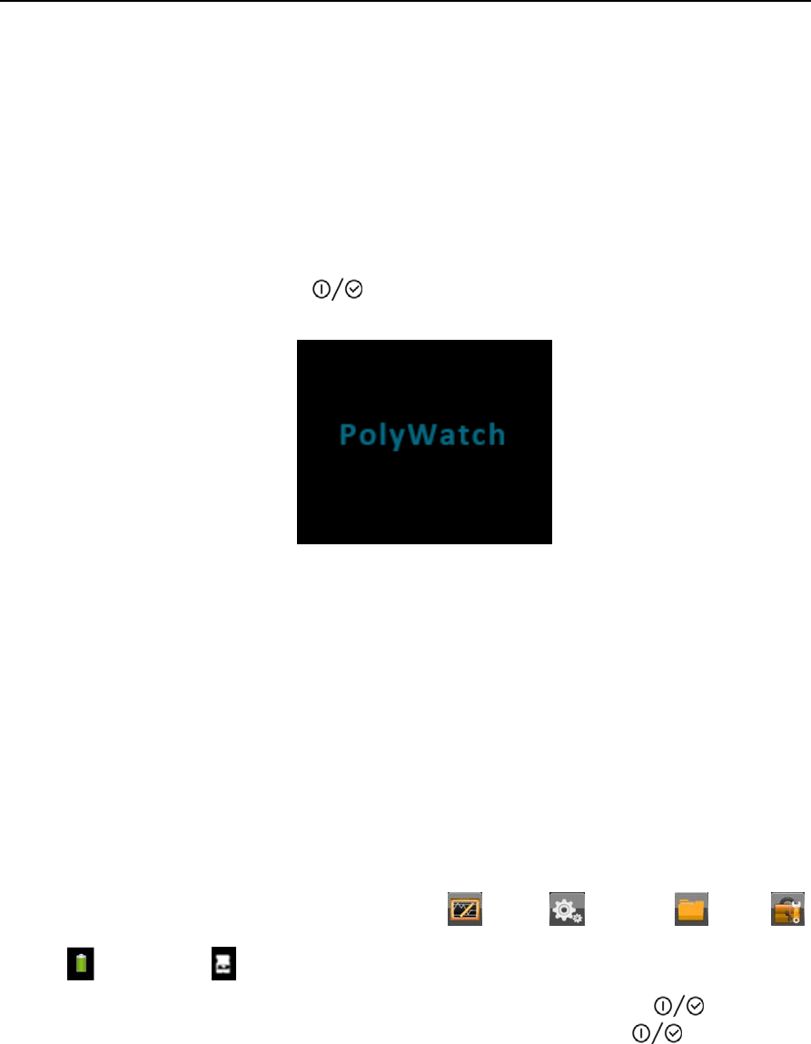
10.2.1 Accessing the Initial Interface
Press and hold the On-Off/OK Button for five seconds, and the initial interface will appear, as
shown in Figure 1-10.
Figure 1-10 Initial interface
CAUTION!
• If the device is not used for a long time, a time setting window will automatically pop up when you
reuse it. Users need to update the date and time according to actual time, then choose “Save and
Exit” to enter the standby interface.
• If the present time displayed on the device is later than the preset record starting time, the device
will immediately begin to record.
10.2.2 Accessing the Standby Interface
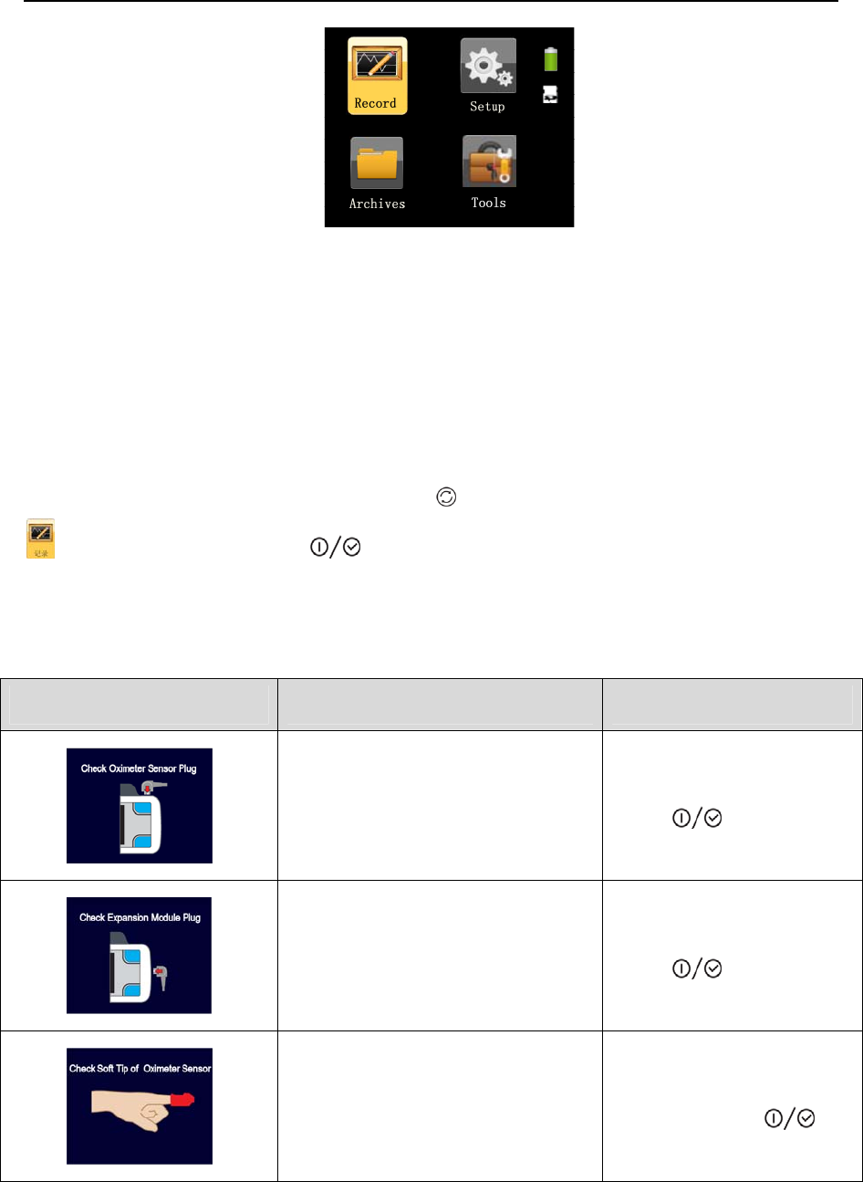
The device automatically enters the standby interface after it is started, as shown in Figure 1-11.
There are six icons in the standby interface: Record , Setup , Archives , Tools ,
Battery and TF card . The yellow frame can switch among the four icons of Record, Setup,
Archives, and Tools, and when it falls on an icon, press the On-Off/OK Button to enter the
corresponding interface. The device can be turned off if the On-Off/OK Button is pressed and
held for five seconds in the standby interface.
YH‐600BProUserManualV1.0
16/49
Figure 1-11 Standby interface
CAUTION!
In all interfaces the screen will dim if there is no operation within the preset screen backlight timeout.
Press any key in five minutes to light up the screen. The device will shut off automatically if there is no
operation for five minutes.10.2.3 Accessing the “Record” Interface
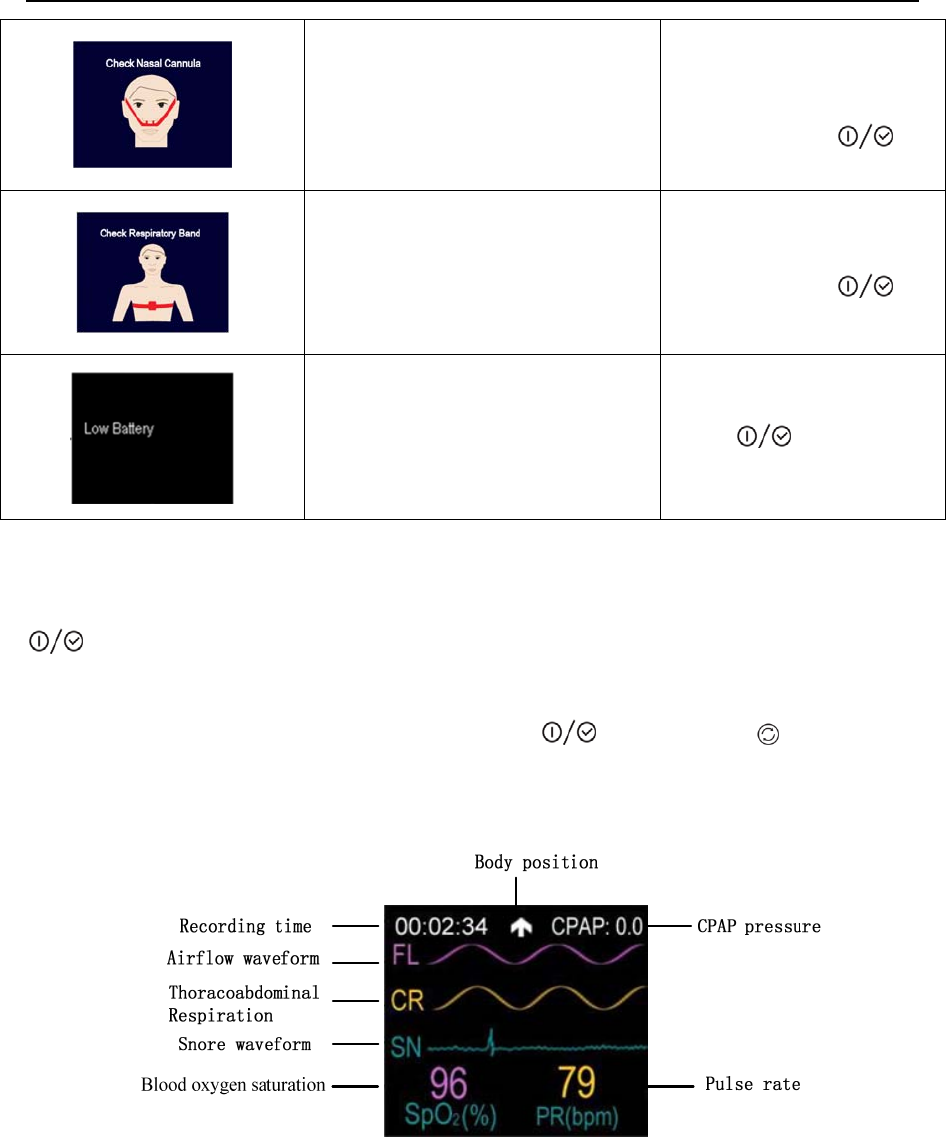
10.2.3.1 Wearing Alert Messages
From the standby interface, press the Shift Button to switch the yellow frame to the “Record” icon
. Press the On-Off/OK Button to enter the “Record” interface. If the device is not worn
properly, a corresponding alert message will appear automatically. See the following Table 1-4 for
detailed information.
Table 1-4 Wearing alert message
Alert Message Causes Alert Removal
When recording starts, the device
cannot detect the SpO2 probe
Insert the SpO2 probe or
press and hold the On-Off/OK
Button to start
recording compulsorily
When recording starts, the device
cannot detect the expansion module kit
(respiration kit)
Insert the expansion module
kit or press the On-Off/OK
Button to start
recording compulsorily
When recording starts, the device can
detect the SpO2 probe, but fails to
collect SpO2 information
Wear the SpO2 finger cot
properly or long-press the
On-Off/OK Button to
start recording compulsorily
YH‐600BProUserManualV1.0
17/49
When recording starts, the device can
detect the expansion module kit, but
fails to collect airflow waveform
information
Wear the Airflow Cannula
properly or long-press the
On-Off/OK Button to
start recording compulsorily
When recording starts, the device can
detect the airflow kit, but fails to collect
thoracoabdominal respiration
information
Wear the respiration effort
belt properly or long-press the
On-Off/OK Button to
start recording compulsorily
The battery is low when recording
starts
Replace the battery or press
and hold the On-Off/OK
Button for three
seconds to enter the “Record”
interface
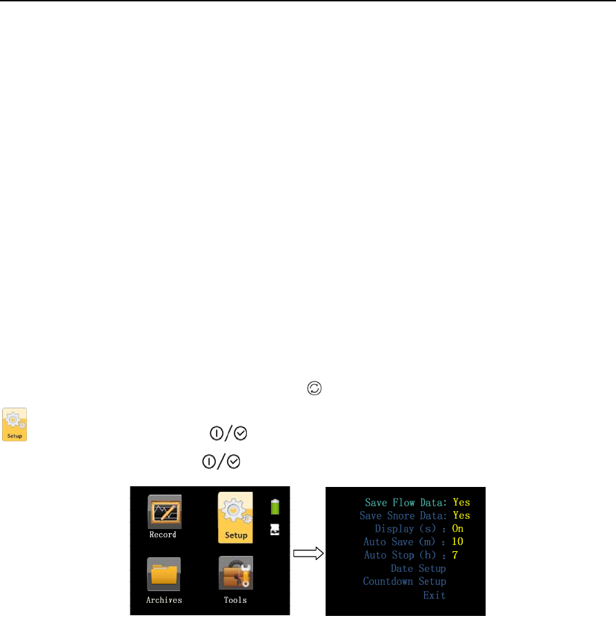
10.2.3.2 “Record” Interface
If there are no wearing alerts, the “Record” interface can be accessed directly. The time notification
(0:00:00) in the upper left corner of the “Record” interface flickers. Press and hold the On-Off/OK Button
for two seconds to start timing and recording monitored data in the device.
If there is no operation within the preset screen backlight timeout (except when the screen is set to stay
bright all the time), the screen will turn off automatically. Pressing any key can light up the screen again.
When recording is completed, press the On-Off/OK Button and Shift Button simultaneously
to exit the “Record” interface and return to the standby interface.
The “Record” interface of YH-600B Pro, as shown in Figure 1-12.
Figure 1-12 “Record” interface of YH-600B Pro
SpO2(%): Blood oxygen saturation expressed in percentage
PR(bpm): Pulse rate expressed as beats per minute (bpm)
Recording time: The length of a recording
Snore: Waveform indicates the occurrence of a snore
YH‐600BProUserManualV1.0
18/49
Airflow waveform: Respiration fluctuations
Thoracoabdominal
Respiration: Chest or abdominal breathing fluctuations
Body position: The user’s body position when the device is in use
Note:
①
The pulse oximeter equipment is calibrated to display functional oxygen saturation.
②
The sampling rate of the SpO2 signal is about 50 Hz, and the update rate of the frame is 1 Hz. So
even there are some filtering methods to process the SpO2 data, it will not delay for a relative long
time to the displaying data.
③
The waveform of the signal is non-normalized so that the software can provide to the operator
that the pulse rate value displayed is potentially incorrect. However, YH-600B Pro which does not
store the waveform data just keeps waveform updating to give the implication of the detector in
working state.
④
If the pulse oximeter sensor is in an abnormal state, the value of SpO2 will be blank.
⑤
The value of SpO2 and PR is calculated by the average of the former eight pulse waveforms.
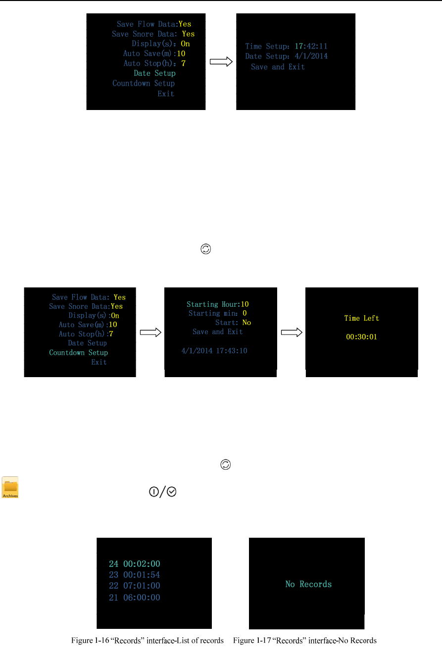
10.2.4 Accessing the “Setup” Interface
From the standby interface, press the Shift Button to switch the yellow frame to the “Setup” icon
. Press the On-Off/OK Button to enter the “Setup” interface. The user can adjust settings,
and press the On-Off/OK Button to confirm the adjustment, as shown in Figure 1-13.
Figure 1-13 “Setup” interface
• Save Flow Data, allowing users to save the data of airflow.
• Save Snore Data, allowing users to save the data of snore.
• Display, allowing users to set the screen backlight timeout.
• Auto Save, saving the data automatically.
• Auto Stop, stop saving the data automatically.
• Date Setup, allowing users to set time and date according to their needs. Select “Save and
Exit” to exit the “Date Setup” interface, as shown in Figure 1-14.
YH‐600BProUserManualV1.0
19/49
Figure 1-14 “Date Setup” interface
CAUTION!
Do not remove the battery when the device is working in the countdown mode, otherwise the countdown
process will be interrupted.
• Countdown Setup, allowing users to set the device to start recording at a certain time
according to their needs. The maximum countdown time is 14 hours, and the device will start
recording automatically when the countdown reaches 0:00:00, as shown in Figure 1-15.
Press and hold the Shift Button for five seconds to exit the “Countdown Setup”
interface.
Figure 1-15 “Countdown Setup” interface
• Exit, select “Exit” to return to the standby interface.
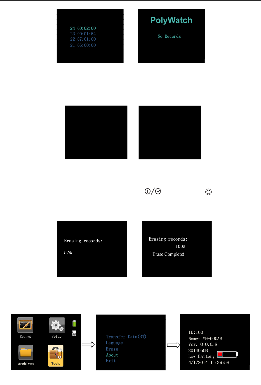
10.2.5 Accessing the “Archives” Interface
From the standby interface, press the Shift Button to switch the yellow frame to the “Archives” icon
. Press the On-Off/OK Button to enter the “Archives” interface. This interface can display
eight records at most, and each record is made up of a serial number and recording time, as shown in
Figure 1-16. When there are no records, the screen will display “No Reccords”, as shown in Figure 1-17.
YH‐600BProUserManualV1.0
20/49
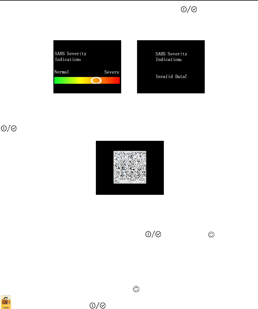
Select a record in the list of records, and press the On-Off/OK Button . If the record is valid, a
ribbon interface will appear, indicating the severity of SAHS. If not, “Invalid Data” will appear, as shown
in Figure 1-18.
Figure 1-18 “SAHS Severity Indication” interface
Select a record in the list of records. If the record is invalid, continue to press the On-Off/OK Button
to trigger the QR code, as shown in Figure 1-19.
Figure 1-19 QR code interface
Scan the QR code by intelligent terminal app “BMC PolyWatch” to view analysis results.
When operations are done, press the On-Off/OK Button and Shift Button to exit the list of
records and return to the standby interface.
WARNING!
The analysis results of the app are for reference only. The diagnosis should be given by your physician.
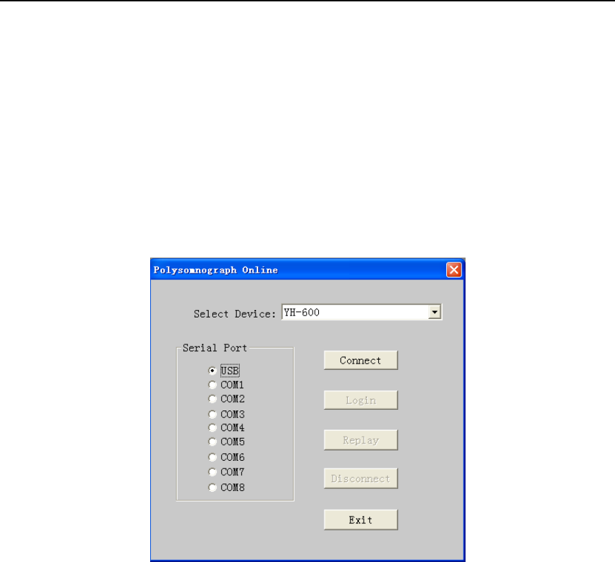
10.2.6 Accessing the “Tools” Interface
From the standby interface, press the Shift Button to switch the yellow frame to the “Tools” icon
. Press the On-Off/OK Button to enter the “Tools” interface. There are five options in this
interface: Transfer Data(BT), Language, Erase, About, and Exit.
The “Transfer Data(BT)” interface shows all records and allows data transmission. If there are no data
records, the screen will display “No Records”, but Bluetooth pairing will not be affected, as shown in
figure 1-20.
YH‐600BProUserManualV1.0
21/49
Figure 1-20“Transfer Data(BT) ” interface
Users can switch among 11 languages in the “Language” interface, as shown in Figure 1-21.
English
Chinese(Simplified)
Japanese
Spanish
Italian
Turkish
German
French
Polish
Russian
Portuguese
Korean
Exit
Figure 1-21 “Language” interface
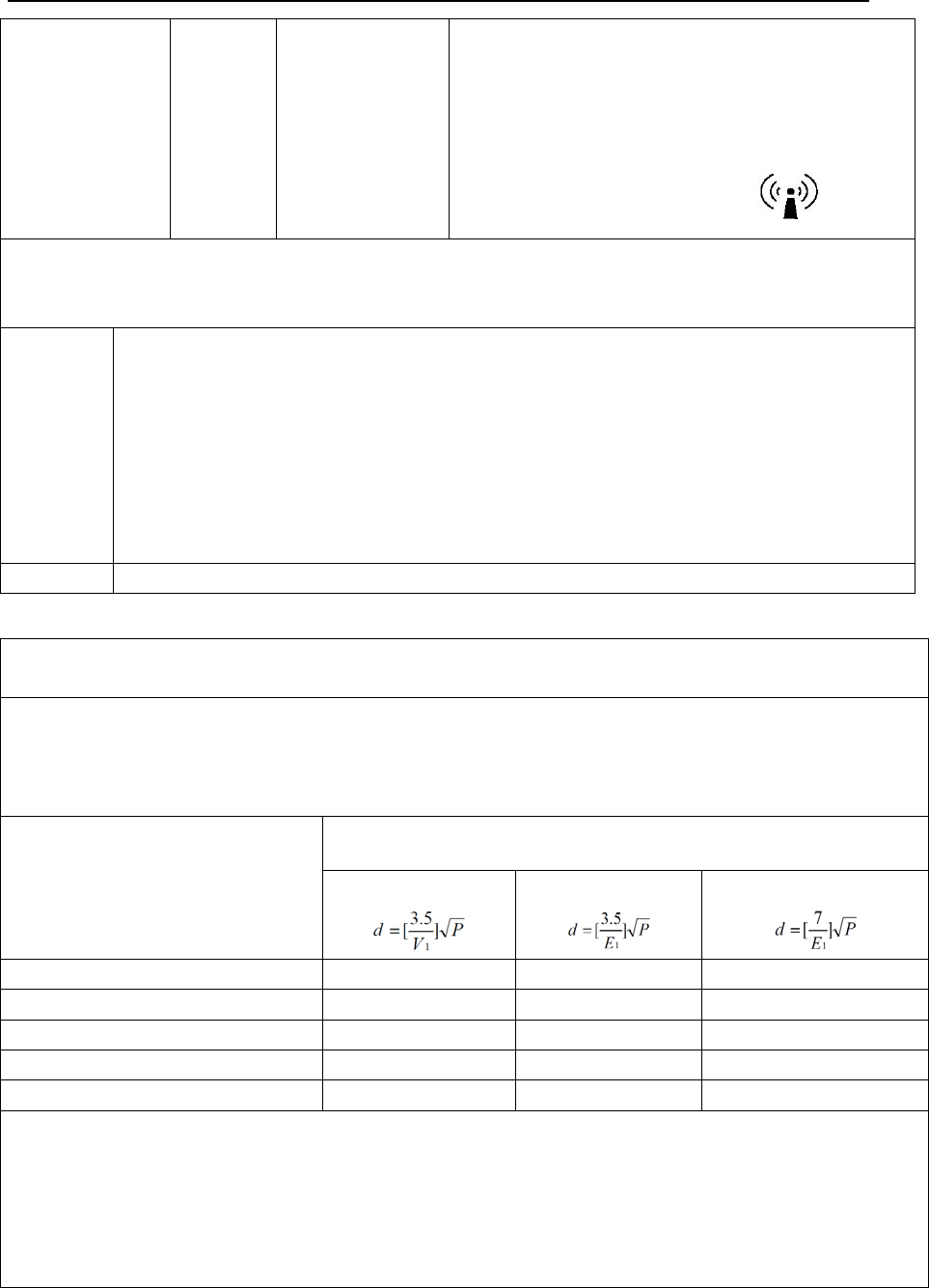
The “Erase” interface shows a question– “Are you sure to erase All records?” To erase all records,
select “Yes”, then press and hold the On-Off/OK Button and Shift Button simultaneously for
two seconds. Then, the interface shows the erasing process which is ended with a message-“Erase
Complete!”, as shown in Figure 1-22.
Figure 1-22“Erase” interface
The “About” interface shows the information, software version and battery power are included, as
shown in Figure 1-23. Press any key to exit.
PolyWatch PolyWatch
Figure 1-23 “About” interface

YH‐600BProUserManualV1.0
22/49
CAUTION!
The cyclic recording mode is adopted. Users do not need to delete data manually as new data will
overwrite the oldest data automatically.
10.2.7 Turning Off the Device
On the standby interface, press and hold the On-Off/OK Button for five seconds to turn off the
device.

YH‐600BProUserManualV1.0
23/49
11. Troubleshooting
Table 1-5 shows troubleshooting.
Table 1-5 Troubleshooting
Problem Possible Cause Solution(s)
Device won’t start Battery installed incorrectly Check battery installation
Battery exhausted Replace battery
Screen flickers Low battery voltage Replace battery
TF card alert TF card is not inserted, is inserted
incorrectly, or is broken
Insert TF card properly or replace
it
Flat airflow waveform
with no fluctuations
Airflow tube is not inserted into the
respiration kit, respiration kit data
cable loosely connects to the main
device, or the tube is bent or
squeezed somewhere
Insert the tube properly, make sure
data cable connects to main device
properly, or contact equipment
supplier for Airflow Cannula
replacement
Flat pulse waveform
with no fluctuations
Pulse oximeter sensor worn in
wrong position
Adjust the sensor’s measurement
point on finger
Flat thoracoabdominal
respiration waveform
with no fluctuations
Respiration effort belt worn
incorrectly Wear respiration effort belt properly
Online analysis feature
missing Recording terminated abnormally
Use the automatically stop
recording feature or manually stop
recording

YH‐600BProUserManualV1.0
24/49
12. Cleaning and Disinfection
12.1 Cleaning
YH-600B Pro was designed to be simple and easy-to-use. Your YH-600B Pro will operate reliably with
good care and regular maintenance.
Cleaning instruction:
Clean YH-600B Pro Main Device
① Turn off YH-600B Pro and take battery out of YH-600B Pro main device.
② Scrub YH-600B Pro main device gently with a damp gauze pad.
③ Dry YH-600B Pro main device with a dry soft gauze pad.
Clean the Respiration Kit
① Detach the Respiration Kit and the CPAP pressure cannula.
② Wipe the Respiration Kit gently with a damp gauze pad.
③ Dry the Respiration Kit with a dry soft gauze pad.
Clean the USB Data Cable
① Disconnect the USB data cable from YH-600B Pro main device.
② Scrub the USB data cable gently with a damp gauze pad.
③ Dry the USB data cable with a dry soft gauze pad.
Clean the Pulse Oximeter Sensor
The pulse oximeter sensor may be surface-cleaned by wiping it with a solution, such as 70% isopropyl
alcohol.
① Detach the pulse oximeter sensor from YH-600B Pro main device.
② Saturate a clean, dry gauze pad with the cleaning solution. Wipe all surfaces of the pulse oximeter
sensor with this gauze pad.
③ Saturate another clean, dry gauze pad with potable water. Wipe all surfaces of the pulse oximeter
sensor with this gauze pad.
④ Dry the pulse oximeter sensor by wiping all surfaces with a clean, dry gauze pad.
Clean the CPAP Pressure Tube
① Detach the CPAP pressure tube from the respiration kit.
② Immerse the CPAP pressure tube completely in a solution ,such as 70% isopropyl alcohol.
③ Rinse the CPAP pressure tube with potable water.
④ Dry the CPAP pressure tube by wiping all surfaces with a clean, dry gauze pad and air dry the lumen
of the CPAP pressure tube.
Cleaning the Wrist Belt
① Wash the wrist belt before first time use, as the dye may run.

YH‐600BProUserManualV1.0
25/49
② Detach the wrist belt from the main device.
③ İt is important to always hand-wash the wrist belt.
④ Wash the wrist belt in warm (approx. 40°C) and soapy water. Use pure soap.
⑤ Rinse the wrist belt well with potable water and allow it to air dry out of direct sunlight.
CAUTION!
• Never use abrasive agents, alcohol, chlorine-containing substances, acetone, or other solvents to
clean the device.
• Do not immerse the device, the airflow kit, or the pulse oximeter sensor in fluids, and ensure that
no fluids penetrate into the product. Do not immerse the main device in water.
• The Airflow Cannula is non-reusable, dispose of it in accordance with local regulations.
12.2 Disinfection
If necessary, i.e. after infectious diseases, uses between patients or if parts have become unusually
dirty, you can disinfect certain parts.
Clean YH-600B Pro parts as instructed above. Disinfect YH-600B Pro as follows:
We recommend CaviCide® liquid for disinfection.
We recommend you to wear suitable gloves (e.g. house-hold or disposable gloves) during disinfection
procedures.
Disinfect the Pulse Oximeter Sensor
The pulse oximeter sensor may be surface-cleaned by wiping it with CaviCide® solution.
① Detach the pulse oximeter sensor from YH-600B Pro main device.
② Saturate a clean, dry gauze pad with the CaviCide® solution. Wipe all surfaces of the pulse oximeter
sensor with this gauze pad.
③ Saturate another clean, dry gauze pad with potable water. Wipe all surfaces of the pulse oximeter
sensor with this gauze pad.
④ Discard the used potable water. Always use fresh volumes of water for each wipe. Do not reuse the
water for wipe or any other purpose. Repeat rinsing the pulse oximeter sensor for two additional times,
for a total of three wipes to remove CaviCide® solution residues.
⑤ Dry the pulse oximeter sensor by wiping all surfaces with a clean, dry gauze pad.
Disinfect the CPAP Pressure Tube
① Detach the CPAP pressure tube from the airflow kit.
② Immerse the CPAP pressure tube completely, filling all lumens and eliminating air pockets, in
CaviCide® solution for a minimum of 5 minutes at 20℃(68℉) or higher to destroy all pathogenic
microorganisms.
③ Rinse the CPAP pressure tube with potable water. Keep the CPAP pressure tube totally immersed

YH‐600BProUserManualV1.0
26/49
for a minimum of 1 minute. Manually flush all lumens with large volumes (not less than 100 ml) of rinse
water.
④ Remove the CPAP pressure tube and discard the rinse water. Always use fresh volumes of water for
each rinse. Do not reuse the water for rinsing or any other purpose. Repeat rinsing the CPAP pressure
tube for two additional times, for a total of three wipes to remove CaviCide® solution residues.
⑤ Dry the CPAP pressure tube by wiping all surfaces with a clean, dry gauze pad and air dry the lumen
of the CPAP pressure tube.
Disinfect the Wrist Belt
① Detach the wrist belt from the main device.
② Immerse the wrist belt completely in CaviCide® solution for a minimum of 5 minutes at 20℃(68℉) or
higher to destroy all pathogenic microorganisms.
③ Rinse the wrist belt with potable water. Keep the wrist belt totally immersed for a minimum of 1
minute in duration.
④ Remove the wrist belt and discard the rinse water. Always use fresh volumes of water for each rinse.
Do not reuse the water for rinsing or any other purpose. Repeat rinsing the wrist belt for two additional
times, for a total of three wipes to remove CaviCide® solution residues.
⑤ Air dry the wrist belt out of direct sunlight.
Sterilization of the device and its components other than recommended is not permitted.
WARNING!
The device shall not be serviced or maintained while in use with a patient.
13. Disposal
Dispose of the device and its package in accordance with local regulations.
Do not dispose device as household waste. To ensure proper disposal of the device, consult an
authorized and certified electronic scrap recovery firm. You can find out their address from your
environmental officer or your municipal authorities.

YH‐600BProUserManualV1.0
27/49
14. EMC Requirements
Guidance and Manufacturer’s Declaration – Electromagnetic Emissions
This device is intended for use in the electromagnetic environment specified below. The user of the device
should assure that it is used in such an environment.
Emissions Test Compliance Electromagnetic Environment - Guidance
RF Radiated Emissions
CISPR 11 Group 1
The device uses RF energy only for its internal function.
Therefore, its RF radiated emissions are very low and are
not likely to cause any interference in nearby electronic
equipment
RF Conducted Emissions
CISPR 11 Class B The device is suitable for use in all establishments
including domestic establishments and those directly
connected to the public low-voltage power supply network
that supplies buildings used for domestic purposes
Harmonic Emissions
IEC 61000-3-2 N/A
Voltage Fluctuations/Flicker
Emissions IEC 61000-3-3 N/A
Guidance and Manufacturer’s Declaration – Electromagnetic Immunity
This device is intended for use in the electromagnetic environment specified below. The user of the device
should assure that it is used in such an environment.
Immunity Test IEC 60601 Test
Level
Compliance Level Electromagnetic Environment - Guidance
Electrostatic
Discharge
(ESD)
IEC 61000-4-2
±6 kV Contact
±8 kV Air
±6 kV Contact
±8 kV Air
Floors should be wood, concrete or
ceramic tile. If floors are covered with
synthetic material, the relative humidity
should be at least 30%
Electrical Fast
Transient/Burst
IEC 61000-4-4
±2 kV for
power supply lines
±1 kV for
input/output lines
N/A Mains power quality should be that of a
typical commercial or hospital environment
Surge
IEC 61000-4-5
±1 kV
differential mode
±2 kV
common mode
N/A Mains power quality should be that of a
typical commercial or hospital environment
Voltage Dips,
Short
Interruptions
and Voltage
Variations on
Power Supply
<5 % UT
(>95% dip in UT)
for 0.5 cycle
40% UT
(60% dip in UT)
N/A Mains power quality should be that of a
typical commercial or hospital environment.
If the user of the device requires continued
operation during power mains interruptions,
it is recommended that the device be
powered from an uninterruptible power

YH‐600BProUserManualV1.0
28/49
Input Lines IEC
61000-4-11
for 5 cycles
70% UT
(30% dip in UT)
for 25 cycles
<5% UT
(>95% dip in UT)
for 5 s
supply or from a battery
Power
Frequency
(50/60 Hz)
Magnetic Field
IEC 61000-4-8
3 A/m 3 A/m Power frequency magnetic fields should be
at levels characteristic of a typical location
in a typical home or hospital environment
Note: UT is the AC mains voltage prior to application of the test level.
Guidance and Manufacturer’s Declaration – Electromagnetic Immunity
This device is intended for use in the electromagnetic environment specified below. The user of the device
should assure that it is used in such an environment.
Immunity Test IEC
60601
Test Level
Compliance Level Electromagnetic Environment - Guidance
Conducted RF
IEC 61000-4-6
Radiated RF
IEC 61000-4-3
3 Vrms
150 kHz
to 80 MHz
3 V/m
80 MHz to
2.5 GHz
N/A
3 V/ m
Portable and mobile RF communication equipment
should be used no closer to any part of the device,
including cables, than the recommended separation
distance calculated from the equation applicable to
the frequency of the transmitter.
Recommended Separation Distance
80~800 MHz
800 MHz~2.5 GHz
where p is the maximum output power rating of the
transmitter in watts (W) according to the transmitter
manufacturer and d is the recommended separation
distance in meters (m).
Field strengths from fixed RF transmitters, as
YH‐600BProUserManualV1.0
29/49
determined by an electromagnetic site survey,
a should be less than the compliance level in each
frequency range.
b Interference may occur in the vicinity of equipment
marked with the following symbol:
Note 1: At 80~800 MHz, the higher frequency range applies.
Note 2: These guidelines may not apply in all situations. Electromagnetic propagation is affected by
absorption and reflection from structures, objects and people.
a
Field strength from fixed transmitters such as base stations for radio (cellular/cordless)
telephones and land mobile radios, amateur radio, AM and FM radio broadcast and TV
broadcast cannot be predicted theoretically with accuracy. To assess the electromagnetic
environment due to fixed RF transmitters, an electromagnetic site survey should be
considered. If the measured field strength in the location in which the device is used exceeds
the applicable RF compliance level above, the device should be observed to verify normal
operation. If abnormal performance is observed, additional measures may be necessary, such
as re-orienting or relocating the device.
b Over the frequency range 150 kHz~ 80 MHz, field strengths should be less than 3 V/m.
Recommended Separation Distance Between Portable and Mobile RF Communication Equipment and the
Device.
The device is intended for use in the electromagnetic environment in which radiated RF disturbances are
controlled. The user of the device can help prevent electromagnetic interference by maintaining a minimum
distance between portable and mobile RF communication equipment (transmitters) and the device as
recommended below, according to the maximum output power of the communication equipment.
Rated Maximum Output Power of
Transmitter /W
Separation Distance According to Frequency of Transmitter/m
150 kHz~80 MHz
80~800 MHz
800 MHz~2.5 GHz
0.01 0.12 0.12 0.23
0.1 0.38 0.38 0.73
1 1.2 1.2 2.3
10 3.8 3.8 7.3
100 12 12 23
For transmitters rated at a maximum output power not listed above, the recommended separation distance d
in meters (m) can be estimated using the equation applicable to the frequency of the transmitter, where P is
the maximum output power of the transmitter manufacturer.
Note 1: At 80~800 MHz, the higher frequency range applies.
Note 2: These guidelines may not apply in all situations. Electromagnetic propagation is affected by
absorption and reflection from structures, objects and people.

YH‐600BProUserManualV1.0
30/49
CHAPTER 2: POLYLOGIC SLEEP ANALYSIS SOFTWARE
System requirements for running the software
Hardware Requirements:
CPU ≥P3 1.0 GB
Memory ≥512 MB
Display Resolution ≥1024×768 DPI
Hard Disk ≥40 GB
Software Platform: Operation system Х 32 : Windows XP/Windows 7/Vista
1. Installation
1.1 Software Installation
①Run the “SETUP.EXE” of YH-600B Pro in the installation CD and enter the setup page.
②Click “Next” to make the software auto-install.
③Click ‘Finish’ to quit when the installation is done. Double-click the new shortcut on desktop to launch
the software.
1.2 Driver Installation
①Double-click the “USBXpressInstaller.exe” in the USB driver folder.
②Click “Next” in the pop-up dialogue boxes, the driver will be installed automatically. This may take
several minutes to finish.
③Click “Finish” when the setup is done.
④A dialogue box displaying the message “found new hardware wizard” appears when the USB data
cable is connected to a computer for the first time. Click “Next” and wait for the installation finished.
Click “Finish” when it is done.
Note: The “found new hardware wizard” dialogue box appears only for the first time of a USB data cable
connection. The software can be directly used afterwards.
2. Patient Information Setup
Before recording, YH-600B Pro allows setting the patient information on a computer via the PolyLogic
Sleep Analysis Software, and displaying the patient name and ID in “About ”interface (Figure1-12) of
YH-600B Pro main device.
1) Start Software
Firstly double-click the shortcut of the analysis software icon on the desktop. The system will enter
YH‐600BProUserManualV1.0
31/49
YH-600B Pro system main window.
2) Connection of YH-600B Pro and Computer
In the power off state of YH-600B Pro, connect one end of the USB data cable to the computer USB port,
and the other end to YH-600B Pro Flow/COM port and then turn on YH-600B Pro. Patient information
can be set on a computer in all interfaces except About Interface.
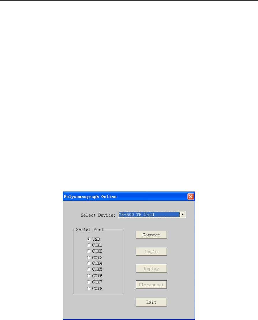
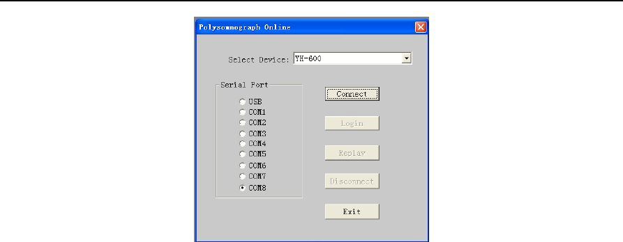
3) Run the Software
Run the software and choose the “File” from the main menu, select "New" to enter the communication
interface. From the “Select Device” drop-down menu, select “YH-600”, and then select the “USB” serial
port. At last, click on “Connect” (Figure 2-1).
Figure 2-1 “Polysomnograph Online” dialog box
4) Connection
If connection succeeds, the "Connect" button will be grayed. And other originally grayed unavailable
buttons will be available now. After connection with the computer (see "Connection of YH-600B Pro and
Computer"), YH-600B Pro will automatically enter the communication status.
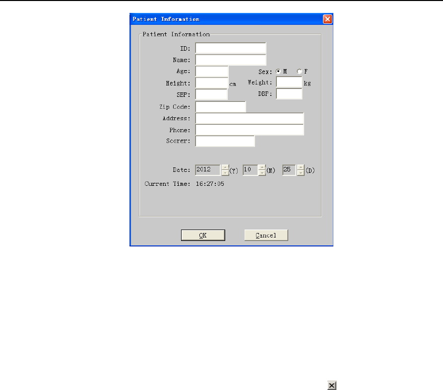
5) Login
After the success of connection, click "Login" button in the “Polysomnograph Online” dialog box and
“Patient Information” dialog box pops up (Figure 2-2).
YH‐600BProUserManualV1.0
32/49
Figure 2-2 “Patient Information” dialog box
6) Enter Patient Information
Enter patient information one by one. When the login information input is finished, select “OK”. There
will be a dialog box indicating “Login OK”, press “OK” to confirm the operation. At this time, select "Exit"
in the dialog box, then YH-600B Pro will automatically exit from the communication status.
7) Exit Program
To return to windows desktop, just click “File” in the menu and click “Exit” or at the top right corner.
3. Data Reception
Data reception is to transmit the recorded data to a computer. Software will analyze the data, and then
the operator can edit the results of the analysis to generate analysis reports. The data receiving process
can be performed through the USB data cable, TF card, or Bluetooth.
Data receiving process is expressed as the following steps.
3.1 Run Software
Firstly double-click the shortcut of the software icon on the desktop, the system will enter analysis
software main interface.
3.2 Connection of YH-600B Pro and Computer
In the power off status of YH-600B Pro, connect one end of the USB data cable to the computer USB
port, and the other end to YH-600B Pro Flow/COM port and then turn on YH-600B Pro. The data can be
transmitted to a computer in all interfaces except countdown interface and “Record” Interface. Go on
with operations of PolyLogic Sleep Analysis Software on the computer to make the connection.
YH‐600BProUserManualV1.0
33/49
WARNING!
• Do not use the USB data cable for communication to computer while the device is recording.
• Only the USB data cable offered by BMC can be used for YH-600B Pro communication to
computer, otherwise it may cause danger to the operator or the patient.
Note
:
①
Do not connect YH-600B Pro to a USB hub.
②
Only one YH-600B Pro can be connected to the computer at any time.
3.3 Data Transmission
①After recording, the data can be transmitted to a computer for further analysis. Besides, YH-600B Pro
allows the analyzed data to be manually edited to remove the recording mistakes.
②Run the software and choose the “File” from the main menu, select "New" to enter the communication
interface. From the “Select Device” drop-down menu, select “YH-600”, and then select the “USB” serial
port. At last, click on “Connect” (Figure 2-1).
③If connection succeeds, the "Connect" button will be grayed. And other originally grayed unavailable
buttons will be available now. After connection with the computer, YH-600B Pro will automatically enter
the communication status.
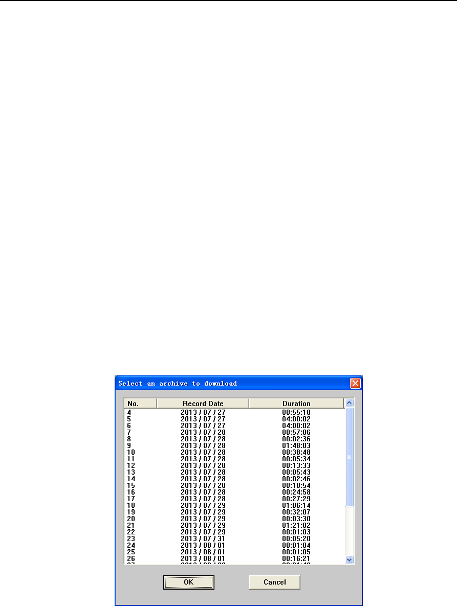
④After connection is established, click “Replay”. A window for selection of data to be downloaded will
pop up, as shown in Figure 2-3 below.
Figure 2-3 “Select an archive to download” dialog box
⑤After selection, click the " OK" button, and “Patient Information” dialog box pops up (Figure 2-4).
YH‐600BProUserManualV1.0
34/49
Figure 2-4 “Patient Information” dialog box
⑥Recording start time is set by the system at the beginning of the recording time which is confirmed by
the internal clock. If YH-600B Pro clock is not correct, modify it in the above login screen. The recording
end time defaults to 12 hours after the recording starts. In fact, in the process of data transmission, the
system can automatically identify the actual end time of record. YH-600B Pro will automatically stop
after data transmission is finished. So there is no need to change the recording end time in normal
situations.
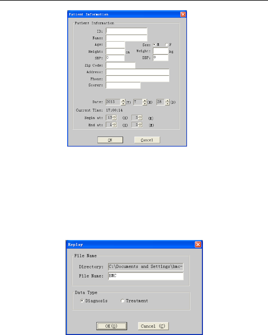
⑦Enter patient information one by one. Click "OK" button and “Replay” dialog box pops up (Figure 2-5).
Figure 2-5 “Replay” dialog box
⑧The first content is “File Name”. The second is “Data Type”. If using YH-600B Pro alone, select
“Diagnosis”. If using YH-600B Pro with CPAP, select “Treatment”. Having the above two contents set up,
click "OK" and then the computer begin to receive the recorded data. When data transmission is
finished, the system returns to communication dialog box. At this time, select "Disconnect" or "Exit" in
the dialog box, YH-600B Pro will then automatically exit from the communication status.
YH‐600BProUserManualV1.0
35/49
Note: If YH-600B Pro is used with CPAP, the CPAP noise could affect the accuracy of the snore testing
results.
WARNING!
• When the user wears the device, it is prohibited to connect the device to the computer through the
USB data cable.
• It is prohibited to connect the device to the computer through the USB data cable other than that
provided by BMC.
3.3.1 TF Card Data Transmission
1) Launching the main device software
Click on the windows shortcut for the data analysis software to launch the software.
2) Connecting the TF card to computer
Remove the TF card from the device when it is turned off. Insert the TF card to a card reader, and
connect it to a computer for data analysis.
3) Data transmission
Data transmission via a TF card is basically the same as that via the USB data cable, except that when
using the TF card, the user should select “YH-600 TF Card” in the “Select Device” drop-down menu
(Figure 2-6).
Figure 2-6 Communication window of the data analysis software
3.3.2 Bluetooth Data Transmission
1) Installing the Bluetooth driver
Insert the Bluetooth adapter into the USB port of a Windows computer, and the operating system will
YH‐600BProUserManualV1.0
36/49
locate the Bluetooth driver automatically. After the driver is installed successfully according to
instructions, a Bluetooth shortcut will appear on the desktop.
Note: Bluetooth adapter involved in the Bluetooth data transmission should be bought by the user. The
following related image-text information is for reference only.
2) Bluetooth data transmission
(1) Main device setting
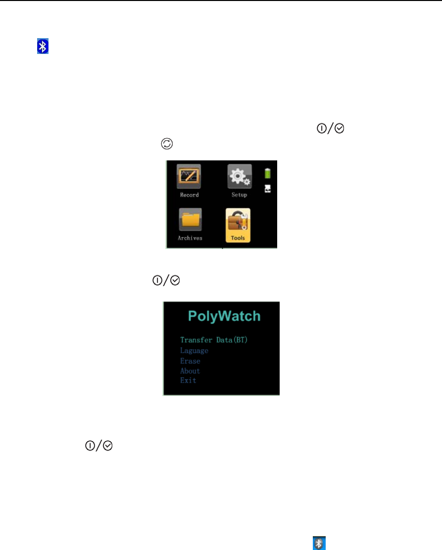
①After an AA battery is installed, long-press the On-Off/OK Button to turn on the device,
and then press the Shift Button to select the “Tools” icon(Figure 2-7).
Figure 2-7 Main device interface
②Press the On-Off/OK Button to enter the “Tools” interface(Figure 2-8).
Figure 2-8 “Tools” interface
After the “Tools” interface is accessed, the first option “Transfer Data(BT)” turns green. Press the
On-Off/OK Button directly to enter the “Transfer Data(BT)” interface. (If there are no records,
the screen will display “No Records”, and the Bluetooth pairing will not be affected.)
(2) Bluetooth pairing
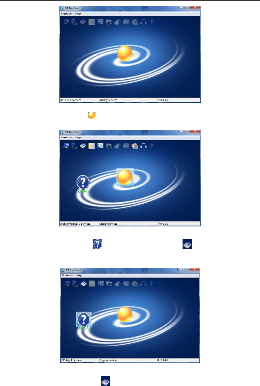
①Insert the Bluetooth adapter into the USB port of the computer.
② Double-click the Bluetooth shortcut to enter the classic Bluetooth interface (Figure 2-9). (If it is
not the classic Bluetooth interface, right-click the Bluetooth icon in the taskbar to choose
classic interface)
YH‐600BProUserManualV1.0
37/49
Figure 2-9 Classic Bluetooth interface
③Double-click the sun icon in the classic interface to start searching for BF10 Bluetooth
devices (Figure 2-10).
Figure 2-10 Bluetooth searching interface
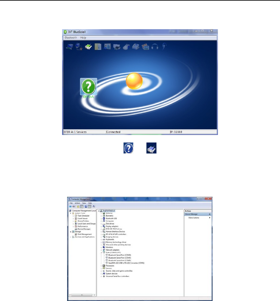
④Double-click the BF10 icon to highlight the serial port icon on the top of the classic
interface, as shown in Figure 2-11 below.
Figure 2-11 Highlighting the serial port icon
⑤Double-click the serial port icon . If connection succeeds, the serial port icon and Bluetooth
YH‐600BProUserManualV1.0
38/49
device icon will turn green, as shown in Figure 2-12. At the same time, a virtual COM port will be
created in the computer.
Figure 2-12 and turn green
Note: Please remember the name of the virtual COM port, and make sure the communication port of the
data analysis software is consistent with this COM port. If the user fails to remember the name of the
virtual COM port, he or she can view the port name by clicking “+” before “Port (COM and LPT)” in
“Device Manager” of the computer, as shown in Figure 2-13.
Figure 2-13 Treeview of Device Manager
(3) Data transmission
Data transmission via Bluetooth is basically the same as that via a USB data cable, except that the user
must select the virtual COM port for Bluetooth pairing in “Serial Port” (Figure 2-14).
YH‐600BProUserManualV1.0
39/49
Figure 2-14 Selecting the virtual COM port
If another device is intended to connect to the computer, repeat the process of data reception. If no data
transmission is needed, click "back" button in the communication window to return to the main interface.
4. Data File Management
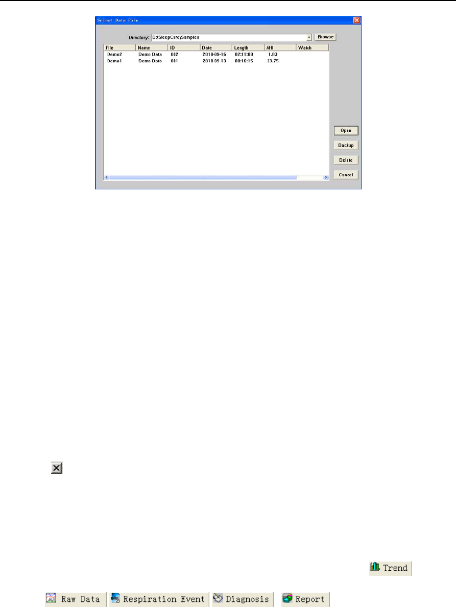
①In the main interface of data analysis software, choose “Open” in “File” of the menu bar, the
system will enter the sleep data management interface. The screen shows the saved data and its
related information in the hard disk (Figure 2-15). The desired data can be easily found by different
orders in this interface.
②First of all, find out the route and catalog of the sleep data by using the “Browse” button. Then
all the files are listed, with the information such as file name, patient name, serial number,
recording date, record length, person on duty and data version etc. The files’ order can be changed
by clicking on the corresponding classification column.
③In the lower right of the interface are the function keys such as Open, Backup, Delete and
Cancel. Click the file name to select the file, and then press the appropriate function key to achieve
data playback, data backup and data deletion.
④Selecting “Cancel” button in the lower right of the interface can return to the main interface of
data analysis software.
YH‐600BProUserManualV1.0
40/49
Figure 2-15 “Select Data File” dialog box
5. Data Playback
In the sleep data management interface, select the sleep data file, and the system will enter the data
playback interface.
If the data have not been analyzed yet, the prompt of auto analysis will be shown on the screen.
After opening the data file, the system will enter the data playback interface. There are the trend chart,
the waveform, the diagnosis result, the analysis report and other interfaces.
5.1 Opening and Closing the Data File
①Multiple data files can be opened simultaneously in the main interface of data analysis software. For
the method to open the data files, please see “Data File Management” part.
②Opening a file may be failed if the file is being used.
③Select the intended file name in the “Window” menu to open the file.
④Clicking in the toolbar or select “Close” in the “File” option in the menu can close the current
window of data file.
5.2 Display of Recorded Data and Analysis Result
The data recording, analysis result and statistical result are shown in 5 interfaces. The order is: Trend,
Raw Data, Respiration Event, Diagnosis and Report.
The first chart displayed in the interface after the file is opened is the trend chart and other
interfaces , , , can be shown via clicking
the corresponding tabs above.
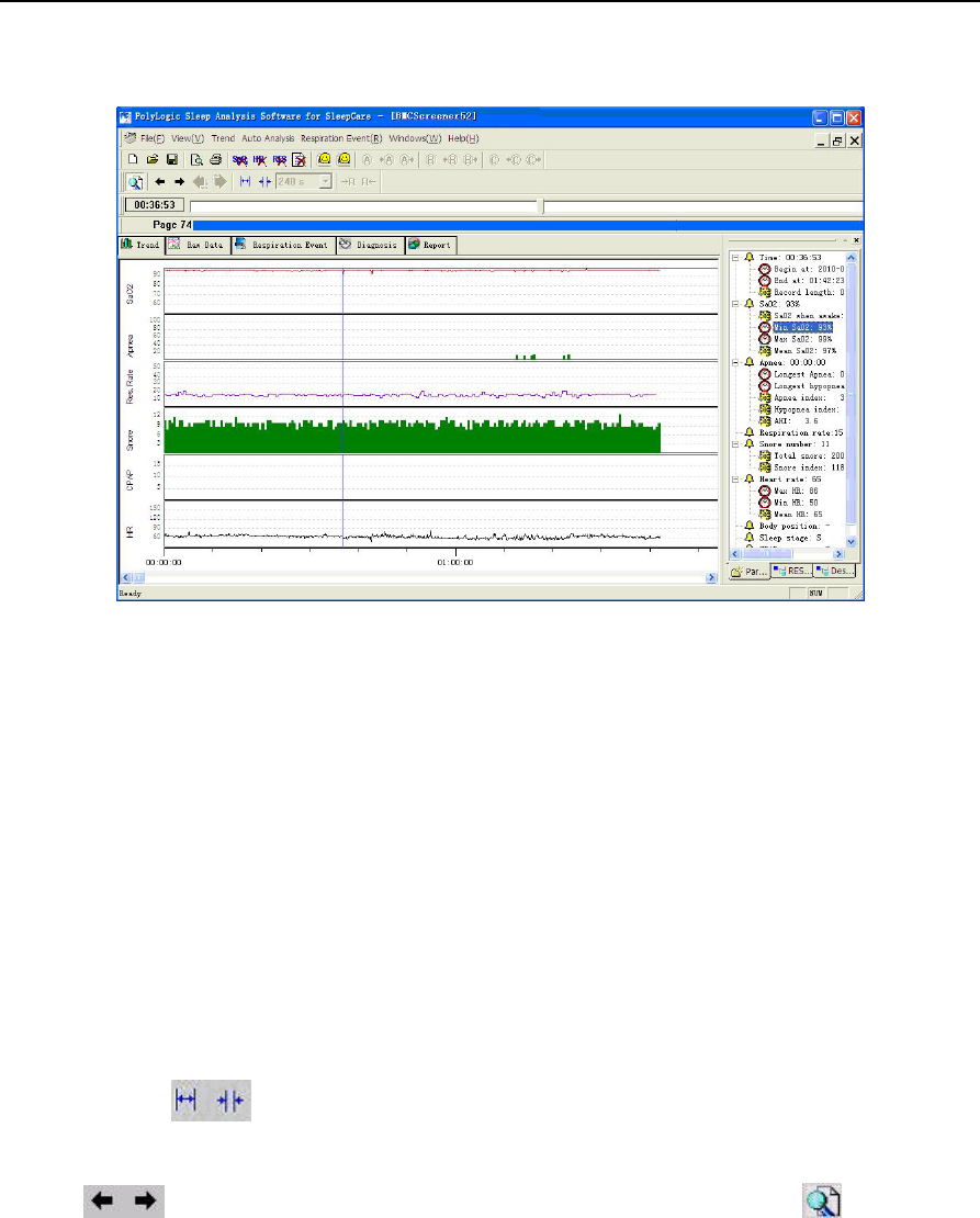
1) Trend
The trend chart demonstrates all the recorded parameters and analysis results during the entire
recording time. By demonstrating multiple parameters, one may observe the different physiological
YH‐600BProUserManualV1.0
41/49
parameters in the same period of time conveniently and may study the relationship between them easily
(Figure 2-16).
Figure 2-16 “Trend” interface
The basic functions in the interface are:
①Parameter browse;
②Parameter deletion;
③Event location;
④Print;
⑤Analysis.
All the operations may be completed through choosing the right option in the menu. Regarding the
commonly used operation, besides the provided menu operation, they may also be done by clicking on
the toolbar buttons.
(1)Parameter browse
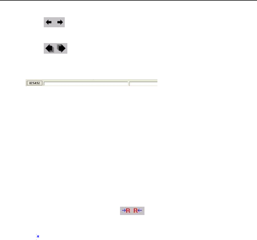
The two buttons in the toolbar may enlarge and reduce the time axis for glances over the
record parameter according to the different time resolution of the tendency change. Clicking the two
buttons may make the cursor move forward and backward. The button may open or
close the display-assistant window, which is able to show each kind of parameter value at the present
time (where the cursor is). Click with a mouse throughout the trend chart can drive the cursor to
anywhere in it.
At the upper part of the trend chart lays a slide scale which can be dragged left and right to change the
cursor position.
The main part of the interface shows the data analysis result trend chart. The items in a top-down order
YH‐600BProUserManualV1.0
42/49
by default is, the saturation of blood oxygen trend chart, the apnea event length trend chart, the
respiratory rate trend chart, the number of snoring trend chart, CPAP pressure trend chart and the heart
rate trend chart. The horizontal axis stands for the elapse of time.
(2)Parameter deletion
Parameters that can be deleted in the trend chart include blood oxygen, heart rate and respiratory rate.
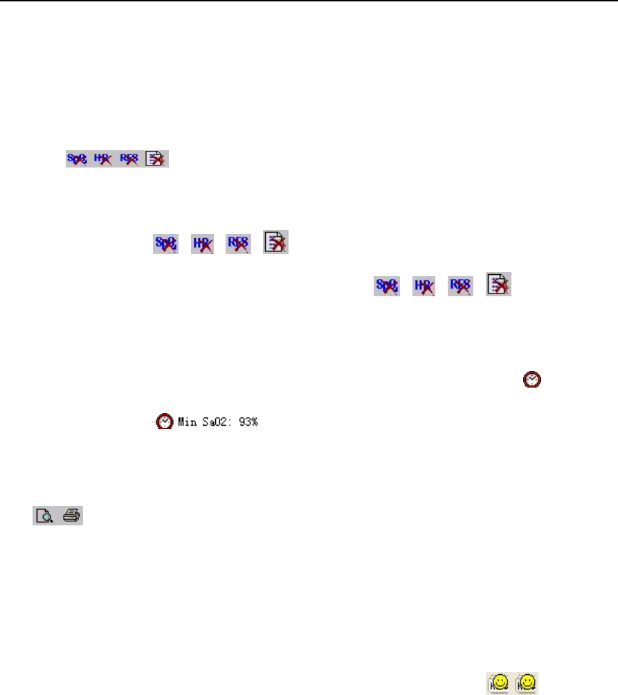
Using the in the toolbar may delete the invalid parameters.
If a certain part of the parameters during a period of time is to be deleted, left-click the mouse and drag it
to select the intended part in the chart, then click the corresponding item from “Trend” of the menu bar. It
can also be done via the 、、 、 icons in the toolbar. If only some points in the chart are
to be deleted, place the cursor at the exact point and click the 、、 、 button directly to
erase them.
(3)Event location
Click on the chart to make the cursor stay anywhere desired. Also, clicking on the “ ” icon in the
parameter page of assistant window can bring the viewer to the very moment when this event occurred.
For example, clicking the item is able to point the cursor to the moment of the lowest
value of oxygen saturation.
(4)Print
Use to print or print preview the charts or reports. The printing function also goes well in other
interfaces.
(5)Analysis
If the data analysis work has not been done when file is opened or some parameters are not correctly
analyzed, a second analysis is necessary after an adjustment to the data. Select the corresponding
options to perform the respiratory analysis and/or snoring analysis.
The toolbar has provided three commonly used analysis shortcuts. The buttons “ ” indicate the
respiration event analysis process and the snoring analyzing process respectively.
The analysis function also works in other interfaces.
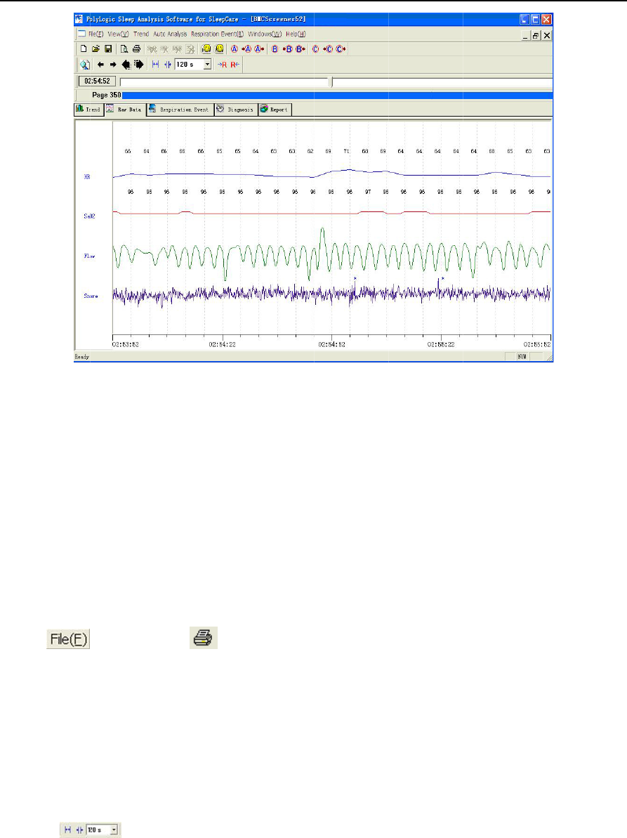
2) Raw Data
This interface can show all the recorded signals both in waveform and in numeric value. By different
speeds of paper, this system can display in the current time scope all the recorded features in this
interface such as the record waveforms, the record parameters as well as the corresponding analysis
results and events.
T
h
①
②
③
④
⑤
⑥
⑦
⑴
S
e
⑵
M
o
c
o
⑶
T
h
T
h
w
h
⑷
T
h
h
e following
o
Print;
Modify displ
a
Modify pape
Modify time
d
Event brow
s
Event edit;
Mark functio
⑴
Print
e
lect
⑵
Modify displ
a
o
ve the curs
o
o
rrect item to
⑶
Modify pap
e
h
is function i
s
h
e tool
h
ich paper m
⑷
Modify time
h
is page pro
v
o
perations m
a
y setup;
r speed;
d
isplay;
s
e;
n.
in the men
u
a
y setup
o
r to a certai
n
change the
g
e
r speed
s
aimed at c
o
in the
oves. The r
a
display
v
ides many
k
Y
H
Fig
u
ay be carrie
d
u
or in
t
n
waveform
a
g
ain and col
o
o
nveniently
o
toolbar can
a
nge is from
8
k
inds of met
h
H
‐600BProUs
43
u
re 2-17 “Ra
w
d
out in this i
t
he toolbar t
o
a
nd right-clic
o
r of the wa
v
o
bserving th
e
zoom in an
d
8
s/page to 4
8
h
ods for the
o
erManualV1
/49
w
Data”inter
f
nterface.
o
print the a
n
k with mous
e
v
eform.
e
waveforms
d
zoom out
t
8
0 s/page.
o
perator to l
o
.0
f
ace
n
alysis repor
t
e
to access t
h
of different t
y
t
he time sc
a
o
cate any pe
r
t
.
h
e pop-up m
e
y
pes.
a
le to chang
e
r
iod of time
c
e
nu, select t
h
e
the speed
c
onveniently
h
e
at
to
YH‐600BProUserManualV1.0
44/49
observe the waveform and its parameters.
The two buttons are used to slightly adjust the time back and forth as to when the waveform
shall be displayed, with five seconds as a pace.
The two buttons are used for page turning with each page length depending on the present
speed of the paper. For example, if the current speed of the paper is 1 minute/page, it shows the
waveform of either previous or next one minute upon each clicking on the icons.
The bar is a time vernier, which could be
dragged back and forth or clicked on to show a waveform in various time ranges.
Moving the mouse cursor to the left or right edges of the waveform where the cursor changes to an
arrow can make the paper moves at the speed of 2 seconds /page automatically.
The display contents can be located in accordance with the markings made by the editor or the various
events in the analysis. Refer to the event browse function and marking function in the following parts for
details.
⑸Event browse
①Breathing event.
All the breathing events are lined out with a series of colorful blocks in the graph, with the serial number,
the type and the length of each one annotated nearby. These breathing events are categorized into HYP
and OSA, which means hypopnea and obstructive sleep apnea respectively. And a previous event or
next event can be easily located by clicking the buttons.
②Snore.
The symbol “ ” indicates a snore. In this operation, evaluations can be made to the sensitivity of
snoring threshold. It can be adjusted by modifying the threshold of snoring identification, therefore
changing the number of snores.
⑹Event edit
The type and length of breathing events can be revised and every event can be inserted or deleted in
this interface.
For changing the breathing event type or deleting any event, right-click on the event and select the
corresponding item to continue.
For changing the length of a breathing event, firstly point the mouse cursor to the beginning or the end
of the block of event, when the mouse arrow changes into a draggable state. Then drag the left or right
edges to change the start and end time.
For event insertion, left-click the mouse and drag it to form rectangular block on the waveform, when a
menu pops up, demonstrating the length of this block (Figure 2-18). Select a corresponding event type
to generate such an event.
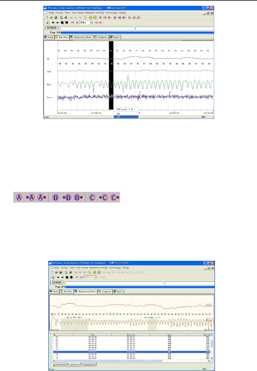
YH‐600BProUserManualV1.0
45/49
Figure 2-18 Respiration Event Edit
⑺Marking function
When the operator feels particularly interested in any recorded part and intends to relocate it on his/her
next opening of the file, he/she may use this marking function, attaching different marks to different
areas of interests.
Three symbols A, B, and C are provided in this function, and “+A”, “+B” or “+C” are shown at the bottom
of waveform.
The in the toolbar is used to make a mark or search for the
previous or next mark. These markings can be kept in file-saving, thus can be relocated quickly upon
later reopening.
3) Respiration Event
This interface has listed all respiration events and their correlations with the statistical data by form
(Figure 2-19).
Figure 2-19 “Respiration Event” interface
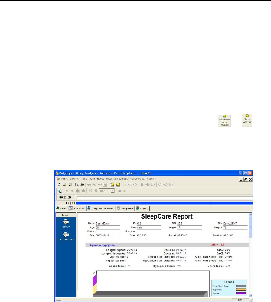
YH‐600BProUserManualV1.0
46/49
The respiration event list may sort according to different statistical items, with just clicking on the
corresponding statistical tags, and the list will be shown in the intended manner.
Clicking on the list or using the〔↑〕、〔↓〕key on keyboard may choose any event in the respiration event
list. Click the corresponding button from the “Respiration Event” drop-down menu to change the type of
an event. The displaying order of the events is not changed at the moment.
Above the respiration event list is the corresponding waveforms where all the respiration events are
characterized by blocks of different color. Right-click on the event block, select the corresponding option
to revise or delete an event. When the mouse arrow becomes draggable at the beginning or end of an
event block, drag it back and forth to shorten or lengthen the time of the respiration event. Also, a
respiration event can be inserted by dragging a rectangular block in the waveform, and the list of
respiration events below will experience changes to the serial number accordingly.
If the respiration event or the snore is to be analyzed for a second time, click or in the
toolbar.
4) Diagnosis
The conditions and results of examination can be reached by selecting the corresponding items in the
drop-down menu. All the above reports can be printed out.
Figure 2-20 Diagnosis Result
5) Report
All analysis results are produced into concise reports after statistical analysis. If the data record has
contained the CPAP pressure, a CPAP pressure report is also included.
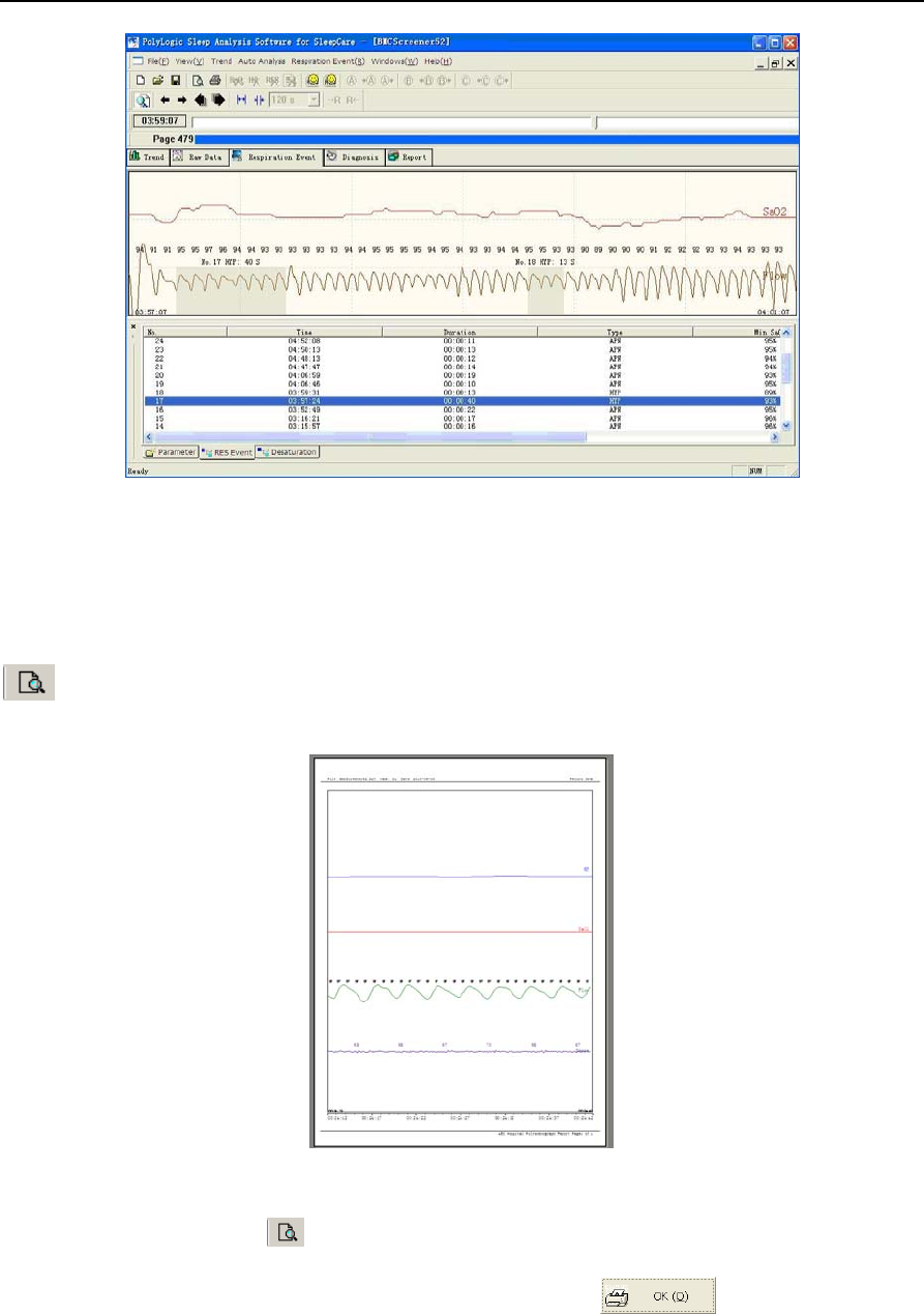
YH‐600BProUserManualV1.0
47/49
Figure 2-21 “Report” interface
6. Print Preview and Output
When the waveform is in need of printing, the waveform page should be activated to display. Press
button or click on preview from the “File” menu under this page to preview the present waveforms
(Figure 2-22).
Figure 2-22 Print and Preview of the Raw Data waveform
In other interfaces, pressing button or clicking on preview from the “File” menu may generate a
window for preview options. Select the intended report and press button, the preview of
report will be shown on the screen (Figure 2-23).
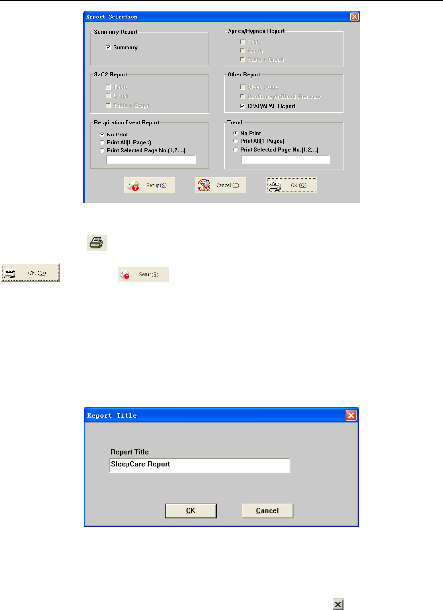
YH‐600BProUserManualV1.0
48/49
Figure 2-23 Print and Preview of the report
Similarly, selecting button in the toolbar, or Print from File menu will show up the window for
preview options. The print work will be done after selecting the intended reports and pressing the
button. Click to change the printer settings.
7. Help
To show software version and service email, just click “Help” button in the menu bar, then click “About”
button.
To alter the report title, just click “Help” button in the menu bar, then select “Report Title”. The “Report
Title” dialog box will pop up (Figure 2-24). Enter the report title, then click “OK” button.
Figure 2-24 “Report Title” dialog box
8. Exit Program
To go back to windows desktop, just click “File” in the menu and click “Exit” or at the top right corner.

other antenna or transmitter.
limits set forth for an
compliance could void the user‘s authority to operate the equipment.
interference
YH‐600BProUserManualV1.0
49/49
CHAPTER 3: SERVICE
1. Technical Support
For technical support or before returning any equipment, call BMC Medical Co., Ltd. at
86-10-51663880.
2. Limited Warranty
BMC Medical Co., Ltd. warrants that YH-600B Pro shall be free from defects of workmanship and
materials and will perform in accordance with the product specifications for a period of one (1) year for
main unit and three (3) months for all accessories from the date of sale by BMC Medical Co., Ltd. to the
dealer. During the warranty period, BMC Medical Co., Ltd. will correct any defects in material or
workmanship to conform to specifications, free of charge. BMC Medical Co., Ltd. reserves the right to
replace YH-600B Pro with a comparable unit. Shipping costs are the responsibility of the purchaser.
This warranty does not cover damage caused by accident, misuse, abuse, alteration and other defects
not related to material or workmanship.
BMC Medical Co., Ltd. disclaims all liability for economic loss, loss of profits, overhead, or
consequential damages which may be claimed to arise from any sale or use of this product.
To exercise the rights under this warranty, contact the local authorized dealers or:
MANUFACTURER:
BMC Medical Co., Ltd.
5/F Main Building, No.19 Gucheng Street West, Shijingshan, Beijing 100043, P.R.China.
Tel: 86-10-51663880
Fax:
86-10-51663880 Ext. 810
EU AUTHORISED REPRESENTATIVE:
Shanghai International Holding Corp. GmbH (Europe)
Eiffestraβe 80, 20537 Hamburg,Germany
Tel: 0049-40-2513175
Fax: 0049-40-255726
Issue date:April 22, 2014
This device complies with part 15 of the FCC Rules. Operation is subject to the following two conditions:
(1) This device may not cause harmful interference, and (2) this device must accept any
received, including interference that may cause undesired operation.
Any Changes or modifications not expressly approved by the party responsible for
FCC Radiation Exposure Statement:
FCC Statement
conjunction with any
This transmitter must not be co-located or operating in
This equipment complies with FCC radiation exposure uncontrolled environment.