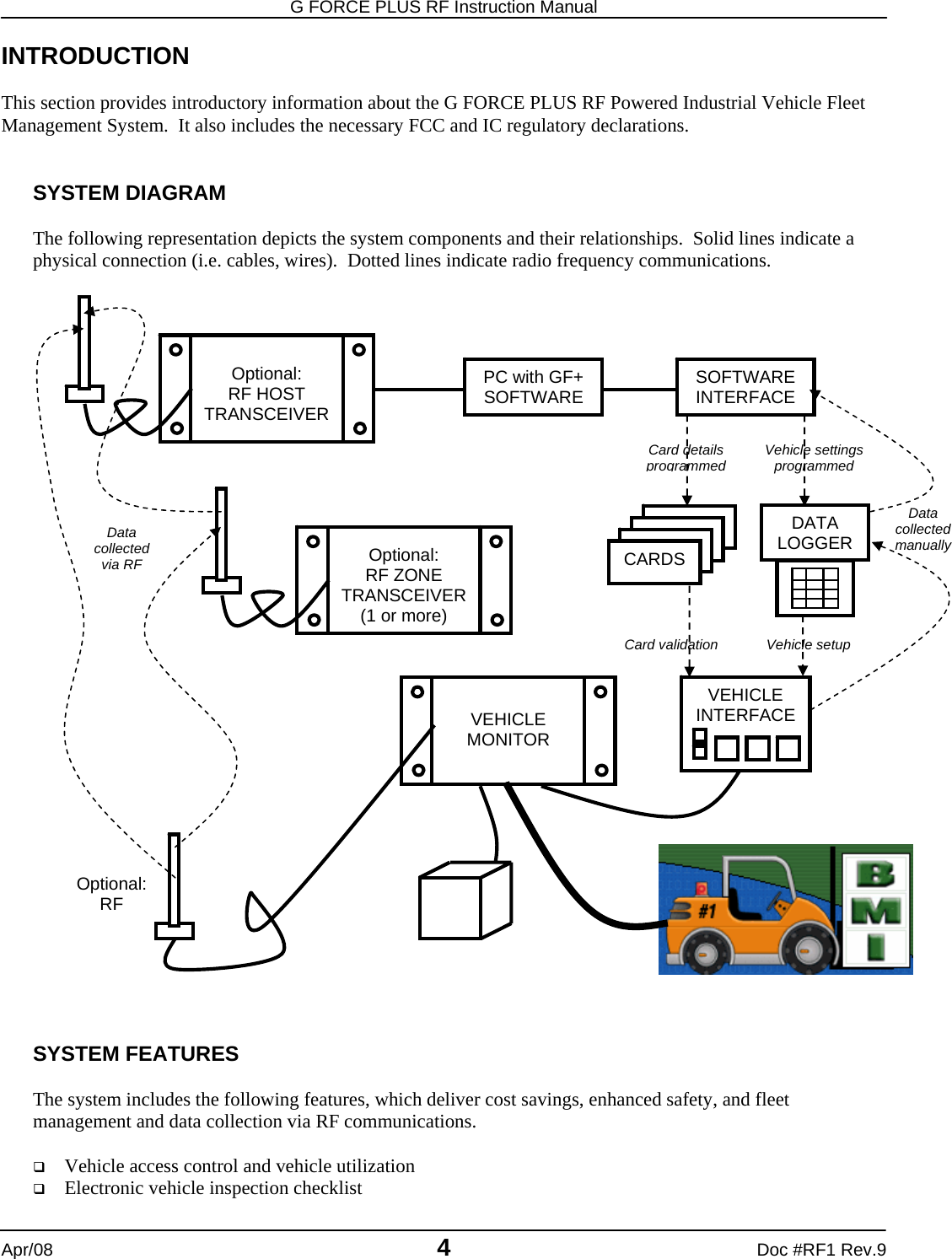
BMI Technologies RFVI Vehicle User Interface RFID Reader User Manual
BMI Technologies Inc. Vehicle User Interface RFID Reader
UserManual.wiki
>
BMI Technologies
>
RFVI User Manual
user manual
Navigation menu
Upload a User Manual
Namespaces
Wiki Guide
HTML
PDF
Info
Views
User Manual
Discussion / Help
Navigation
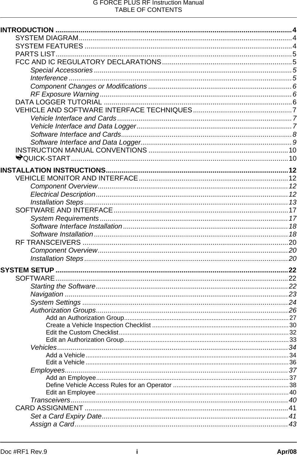
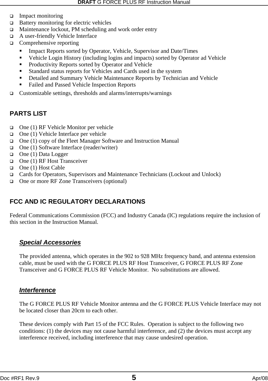
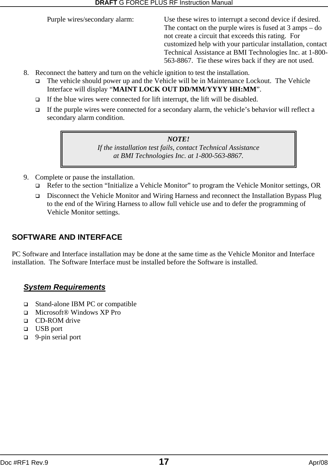
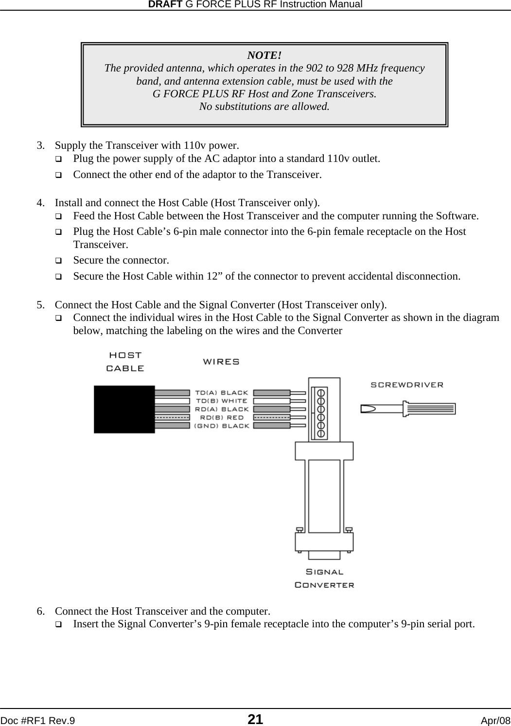
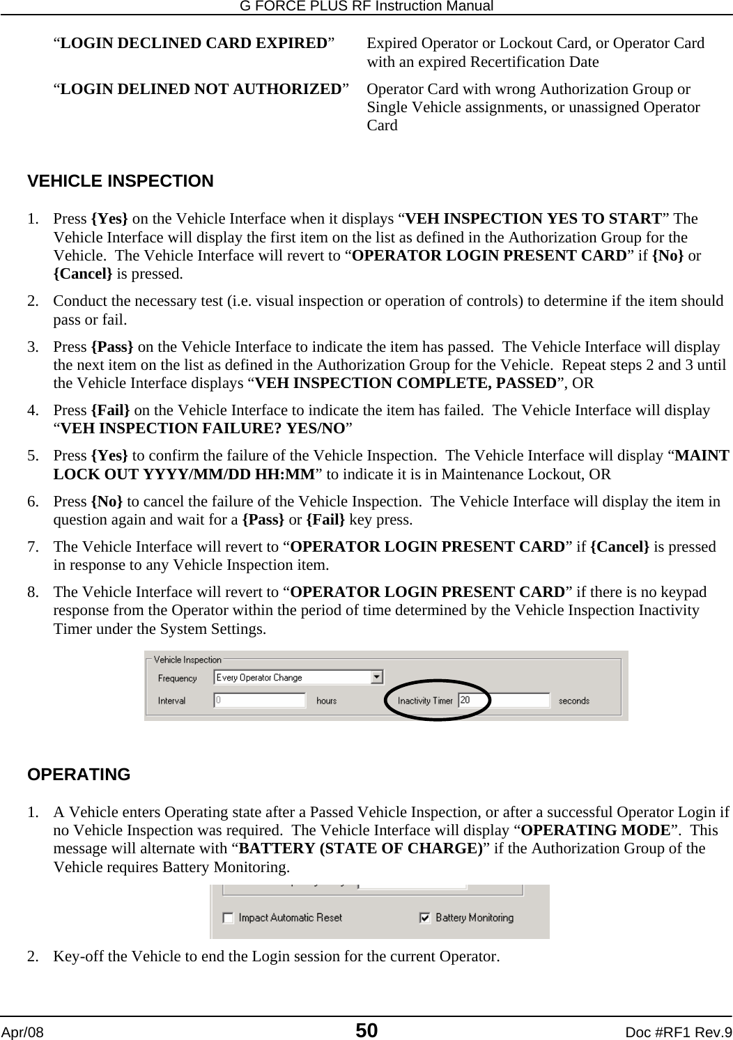
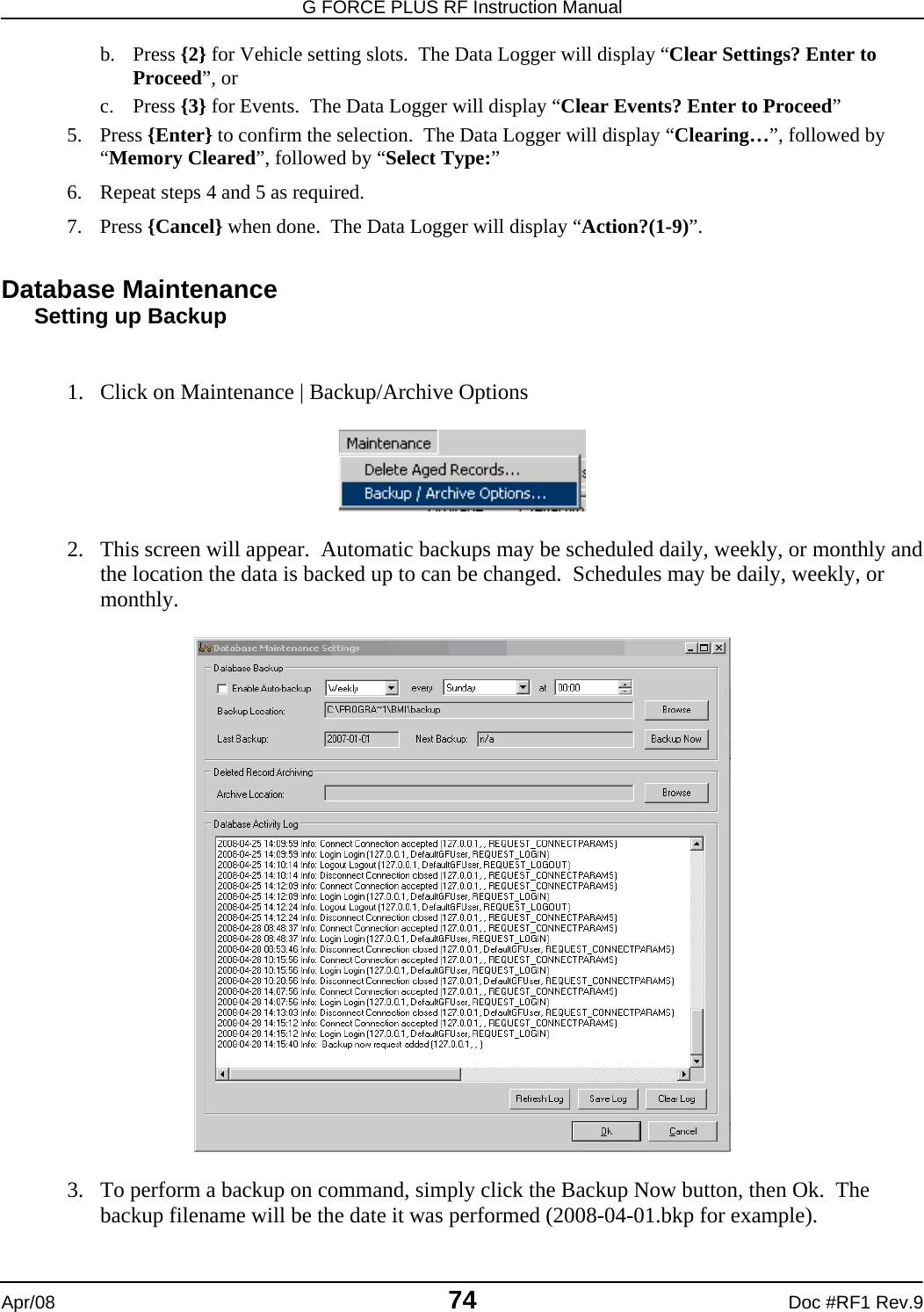
![G FORCE PLUS RF Instruction Manual Apr/08 8 Doc #RF1 Rev.9 3. Hold the Data Logger parallel to the face of the Vehicle Interface, making sure they are within 1” of each other. 4. Listen for a single beep from the Vehicle Interface. This indicates the Data Logger has been recognized. 5. Refer to instructions for individual functions to learn when the Vehicle Interface / Data Logger interaction is complete for that function. 6. When the interaction is complete, remove the Data Logger from the Vehicle Interface and read the Vehicle Interface display for further information. 7. If the Vehicle Interface fails to recognize the Data Logger, remove it from the Vehicle Interface by approximately 12” and retry. Software Interface and Cards 1. Hold the Card parallel to the top of the Software Interface, making sure they are within 1” of each other (or lay the Card on the Software Interface). 2. Initiate the interaction between the Software Interface and Card by selecting the desired task from the Fleet Manager Software. 3. Watch the Software for progress of the interaction. 4. Click the [OK] button to confirm completion of the interaction when prompted by the Software. 5. Remove the Card from the Software Interface.](https://usermanual.wiki/BMI-Technologies/RFVI/User-Guide-941196-Page-10.png)
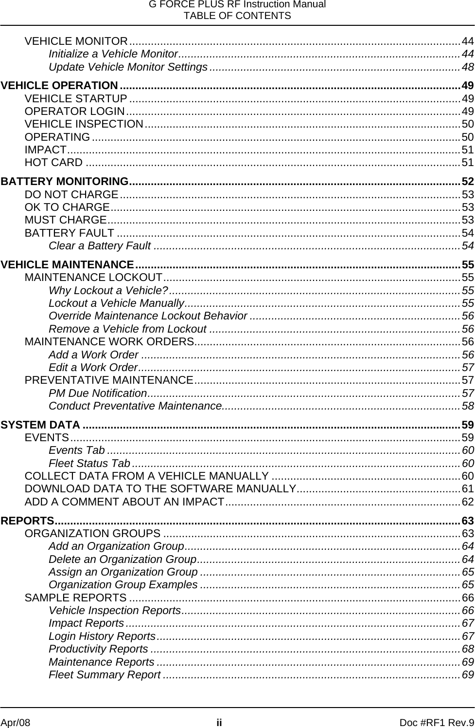
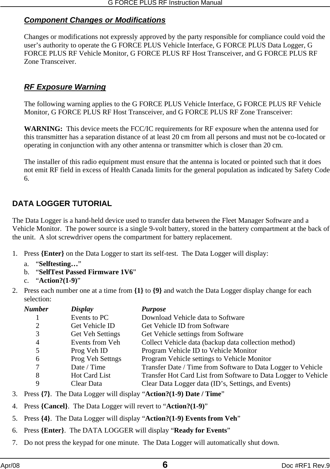
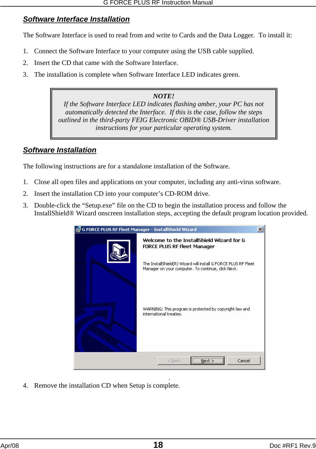
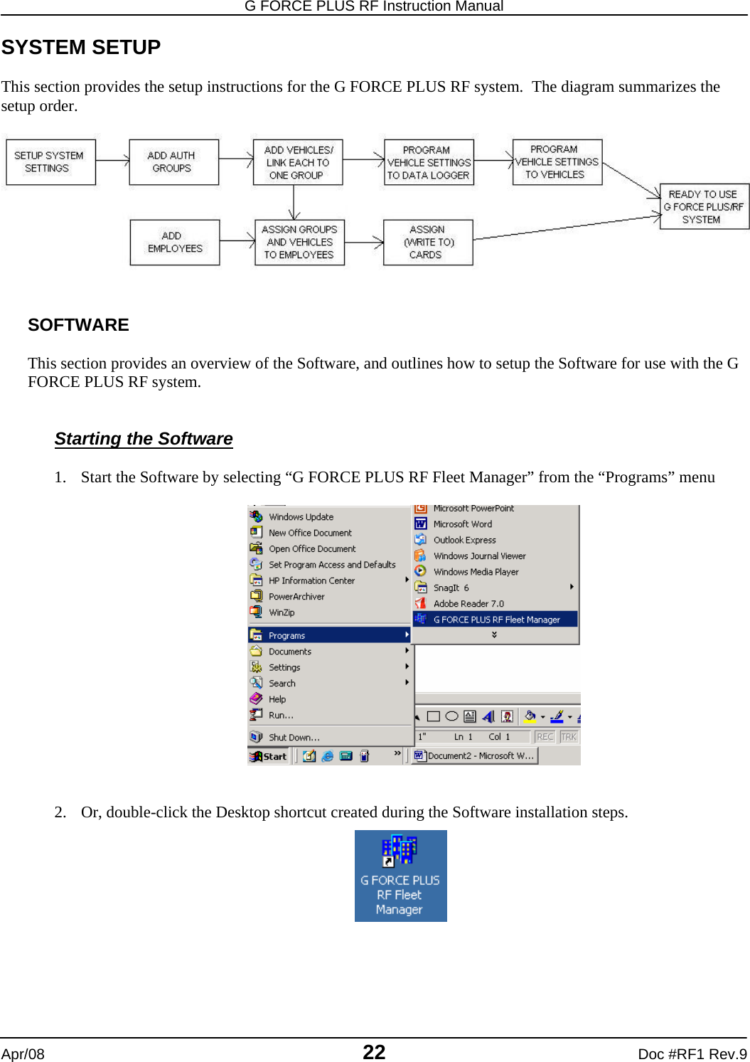
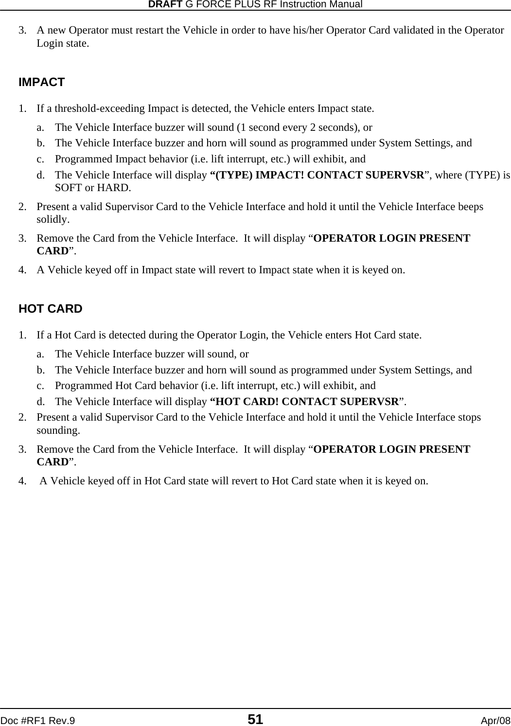
![DRAFT G FORCE PLUS RF Instruction Manual Doc #RF1 Rev.9 9 Apr/08 6. If the interaction fails, remove the Card from the Software Interface by approximately 12” and retry. Software Interface and Data Logger 1. Prepare the Data Logger for the interaction by selecting the desired Data Logger function. 2. Hold the Data Logger parallel to the top of the Software Interface, making sure they are within 1” of each other (or lay the Data Logger on the Software Interface). 3. Initiate the interaction between the Software Interface and Data Logger by selecting the desired task from the Fleet Manager Software. 4. Watch the Software for progress of the interaction. 5. Click the [OK] button to confirm completion of the interaction when prompted by the Software. 6. Remove the Data Logger from the Software Interface. 7. If the interaction fails, remove the Data Logger from the Software Interface by approximately 12” and retry.](https://usermanual.wiki/BMI-Technologies/RFVI/User-Guide-941196-Page-11.png)
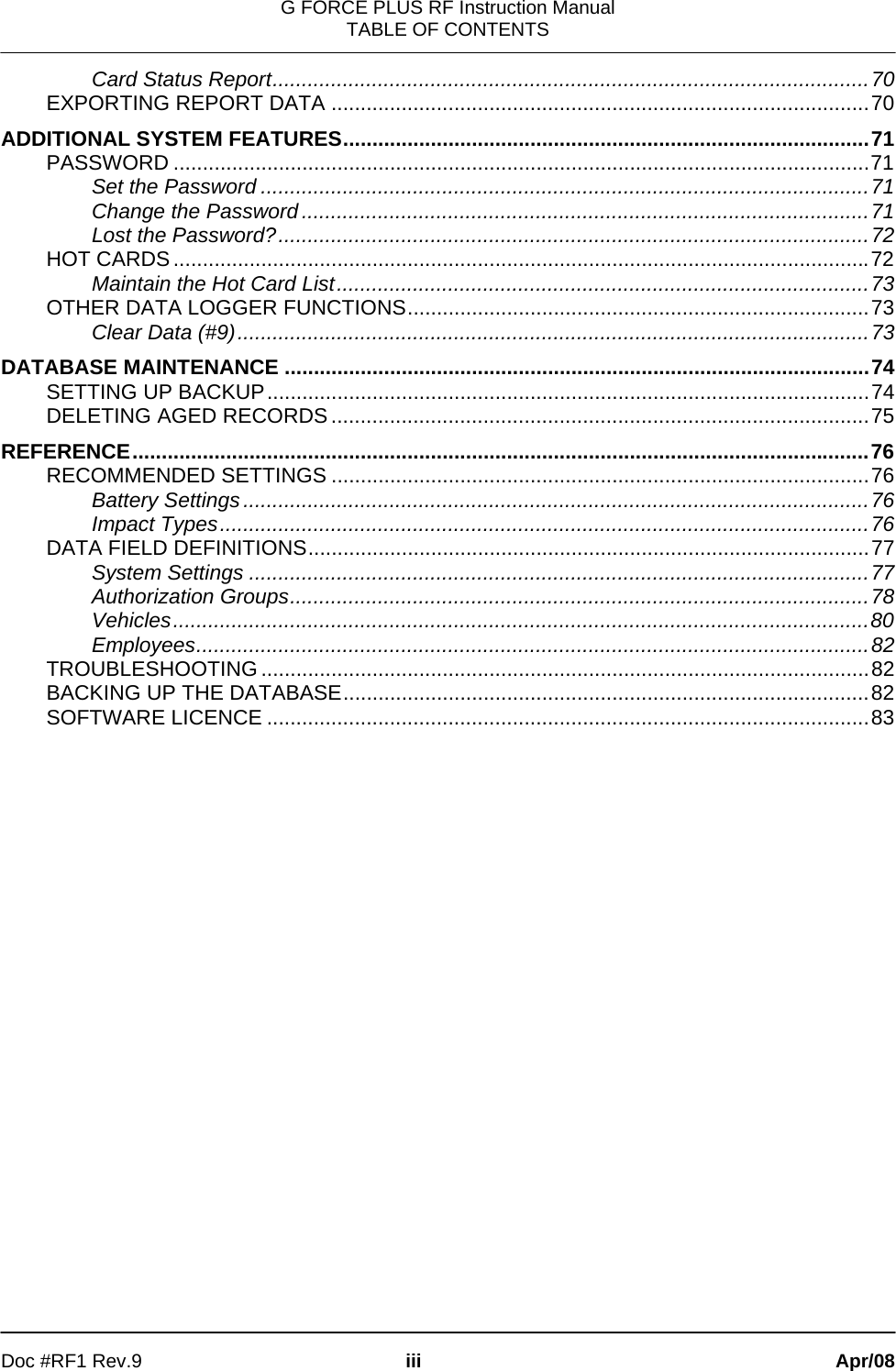
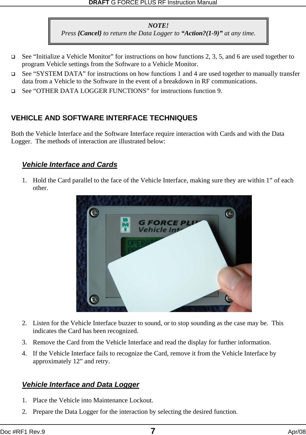
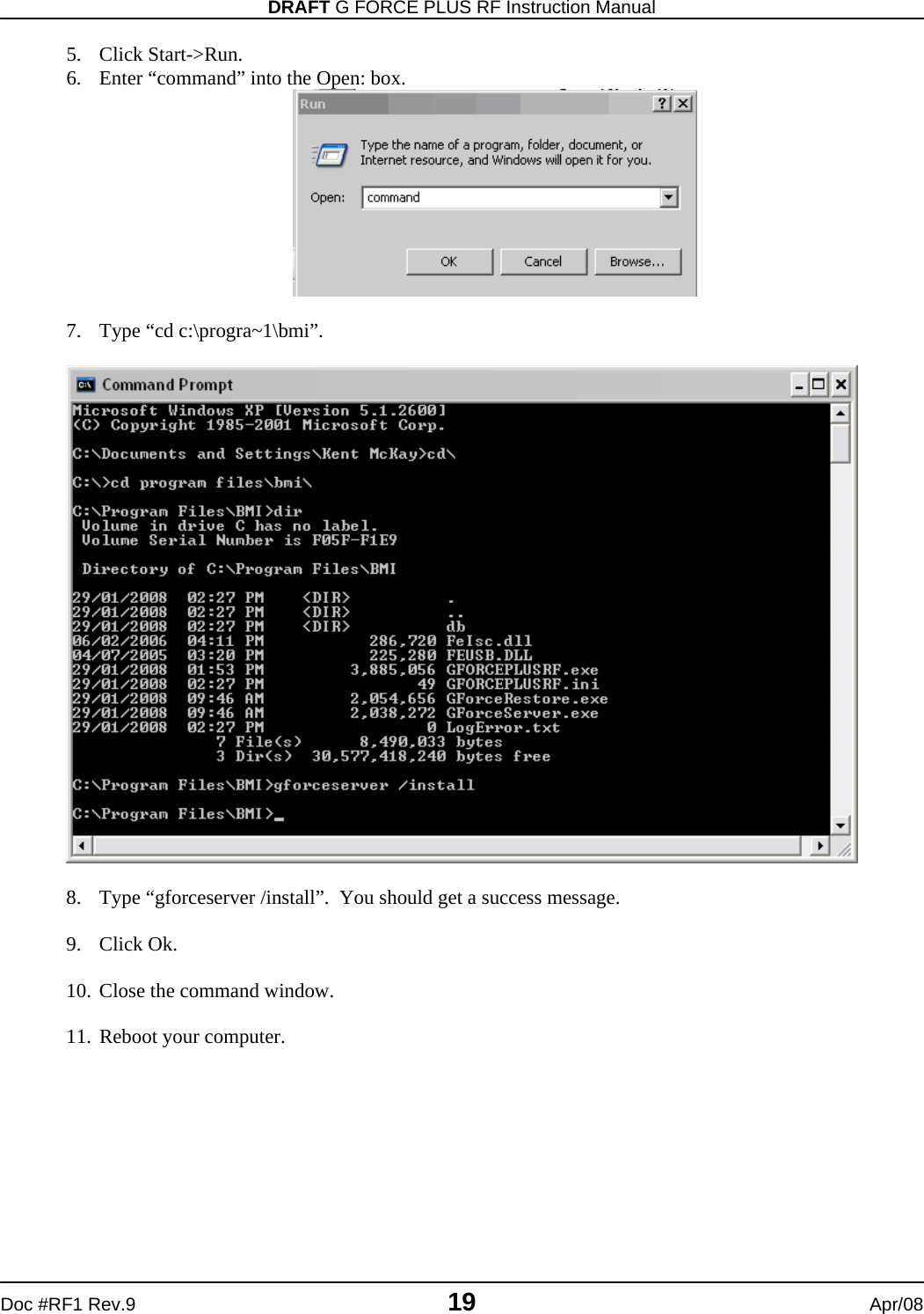
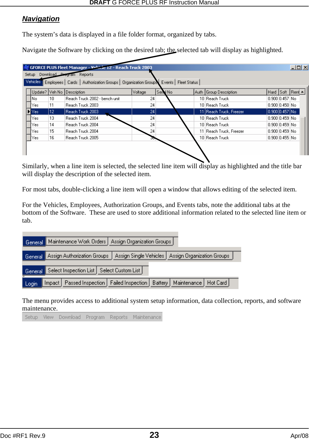
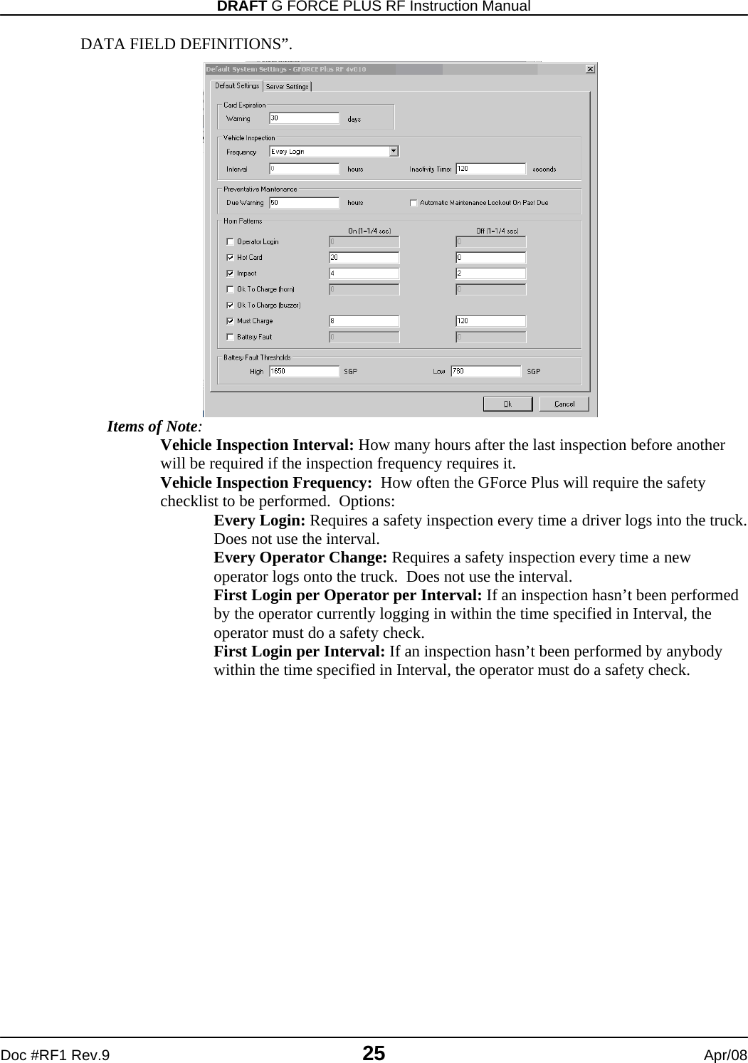
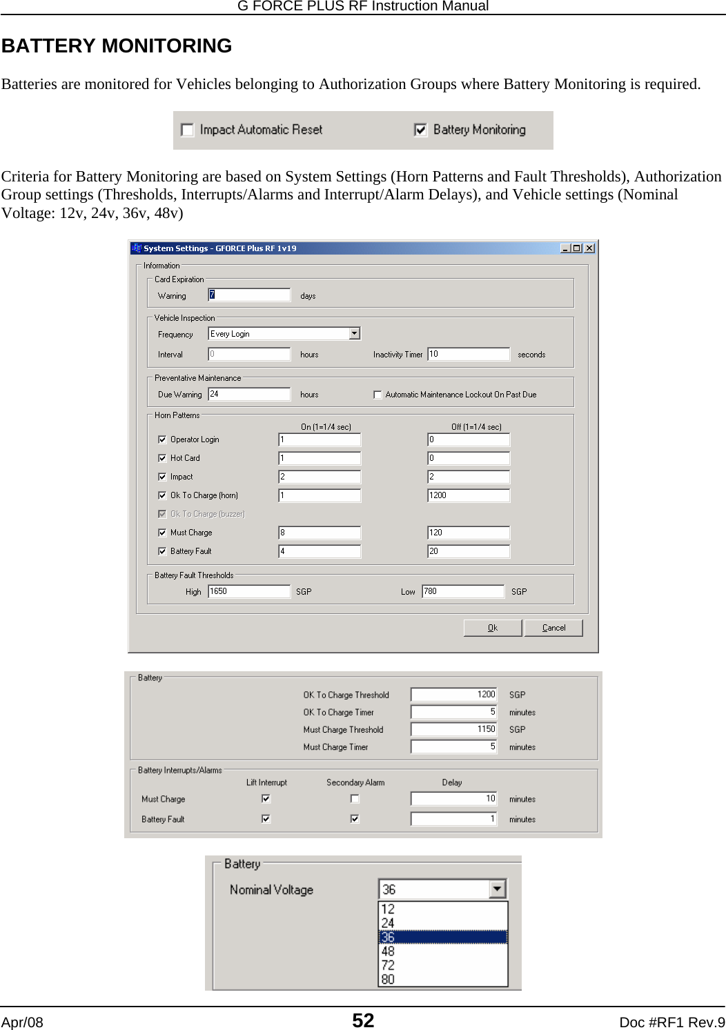
![G FORCE PLUS RF Instruction Manual Apr/08 10 Doc #RF1 Rev.9 INSTRUCTION MANUAL CONVENTIONS Software buttons [Add] Software tabs Vehicles Software menu items Setup | System Settings Software windows “Add Vehicle” Software fields Hours Data Logger keys {Cancel} Data Logger display “No Events!” Vehicle Interface keys {Pass} Vehicle Interface display “OPERATOR LOGIN PRESENT CARD” QUICK-START This Quick-Start section summarizes the system setup steps without providing detailed how-to instructions. Complete them in the order shown. Detailed instructions follow beginning with the “INSTALLATION INSTRUCTIONS”. Settings are described in the section “](https://usermanual.wiki/BMI-Technologies/RFVI/User-Guide-941196-Page-12.png)
![DRAFT G FORCE PLUS RF Instruction Manual Doc #RF1 Rev.9 11 Apr/08 DATA FIELD DEFINITIONS”. 1. Install the Vehicle Monitors and Interfaces. 2. Install the Fleet Manager Software and Interface. 3. Install the RF Transceivers. 4. Set up the Fleet Manager Software. a. Define settings that apply to all Vehicles (Setup | System Settings menu). b. Define (up to 64) Authorization Groups and group settings (Authorization Groups tab). i. Add Authorization Groups and settings ([Add] button). ii. Select Vehicle Inspection checklist (Inspection List lower tab). iii. Select more Vehicle Inspection checklist items (Custom List lower tab). iv. Add more user-defined checklist items if required (Setup | Custom Check List menu). c. Define Vehicles and Vehicle settings and link each Vehicle to one Authorization Group (Vehicles tab, [Add] button). d. Define Employees and vehicle access rules for Employees (Employees tab). i. Add Employees and Employee details ([Add] button). ii. Assign (up to 64) Authorization Groups to each Operator (Assign Authorization Groups lower tab). iii. Assign (up to 32) Single Vehicles to each Operator (Assign Single Vehicles lower tab). e. Customize RF Transceiver descriptions (Setup | Zone Description menu). 5. Assign Cards to Employees. 6. Initialize the Vehicle Monitors with the Data Logger. 7. Begin system operation.](https://usermanual.wiki/BMI-Technologies/RFVI/User-Guide-941196-Page-13.png)
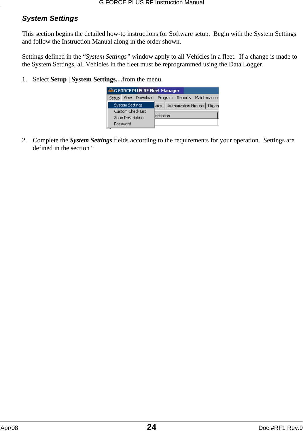
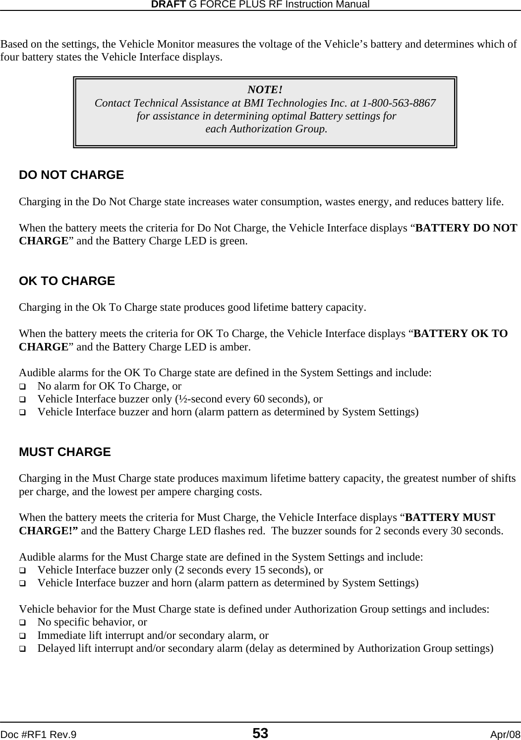
![G FORCE PLUS RF Instruction Manual Apr/08 26 Doc #RF1 Rev.9 3. Radio Comm Port under the Server Settings tab is where you set which Serial port on the computer the Host Transceiver is connected to. 4. Click the [OK] button to save the changes. Reboot if required. Authorization Groups Primarily, Authorization Groups are how vehicle access rules are defined. Each Vehicle is assigned to a single Authorization Group and each Operator is assigned up to 64 Authorization Groups. The Operator then has access to all Vehicles in the assigned Authorization Groups. Consider creating a unique Authorization Group where vehicles require different: Vehicle Inspection checklists Operating and training requirements (i.e. electric vs. internal combustion, pallet jacks vs. order pickers) Preventative Maintenance scheduling (i.e. leased vs. owned) Interrupts and alarms (re: battery monitoring for electrics vs. none for internal combustion) Battery settings due to operating environment (i.e. freezer vehicles) NOTE! Authorization Groups must be set up before NOTE! A reboot is required when the Port Number is changed.](https://usermanual.wiki/BMI-Technologies/RFVI/User-Guide-941196-Page-28.png)
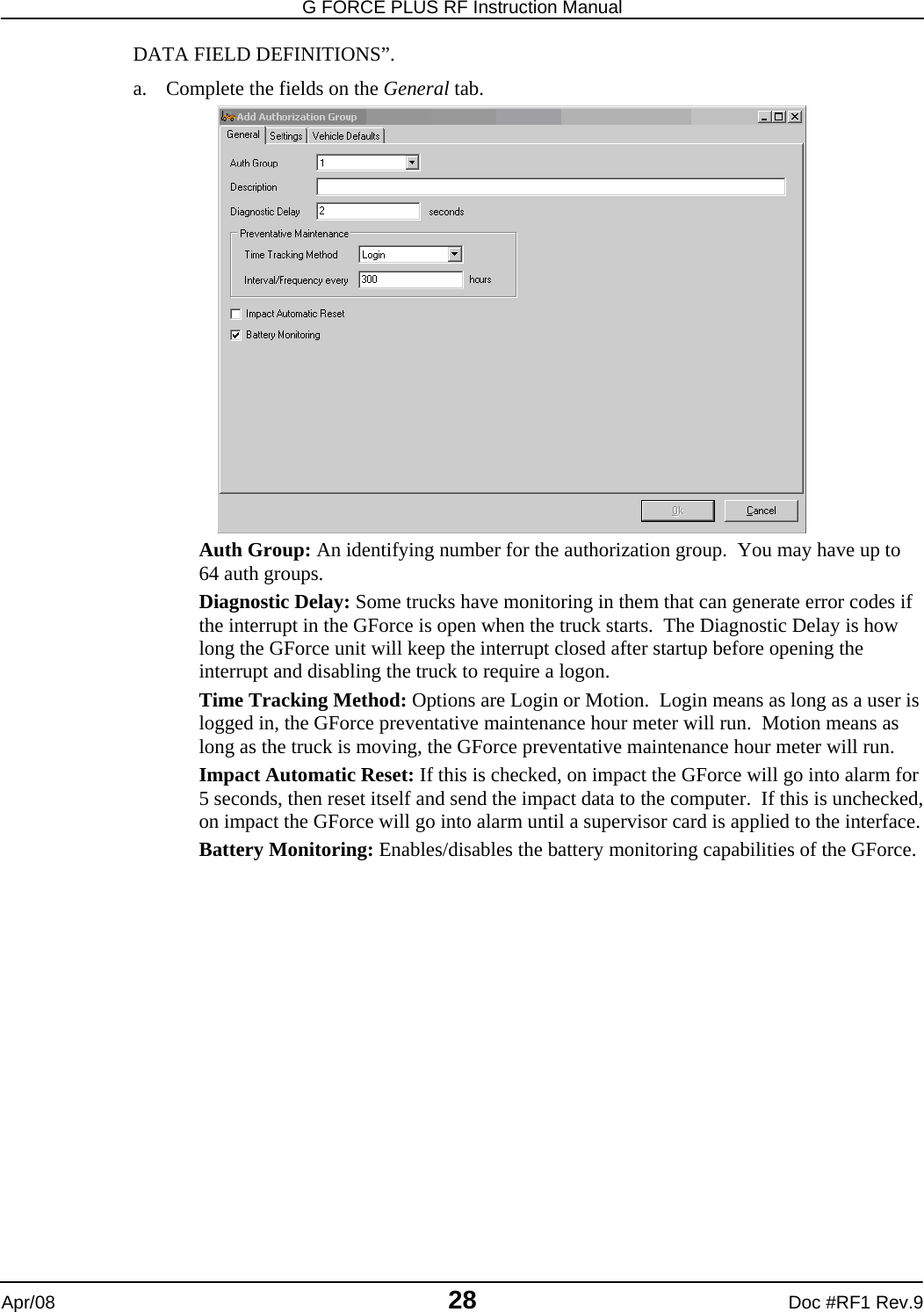
![DRAFT G FORCE PLUS RF Instruction Manual Doc #RF1 Rev.9 27 Apr/08 Add an Authorization Group 1. Select the Authorization Groups | General tab. 2. Click the [Add] button to open the “Add Authorization Group” window. Settings are explained in the section “](https://usermanual.wiki/BMI-Technologies/RFVI/User-Guide-941196-Page-29.png)
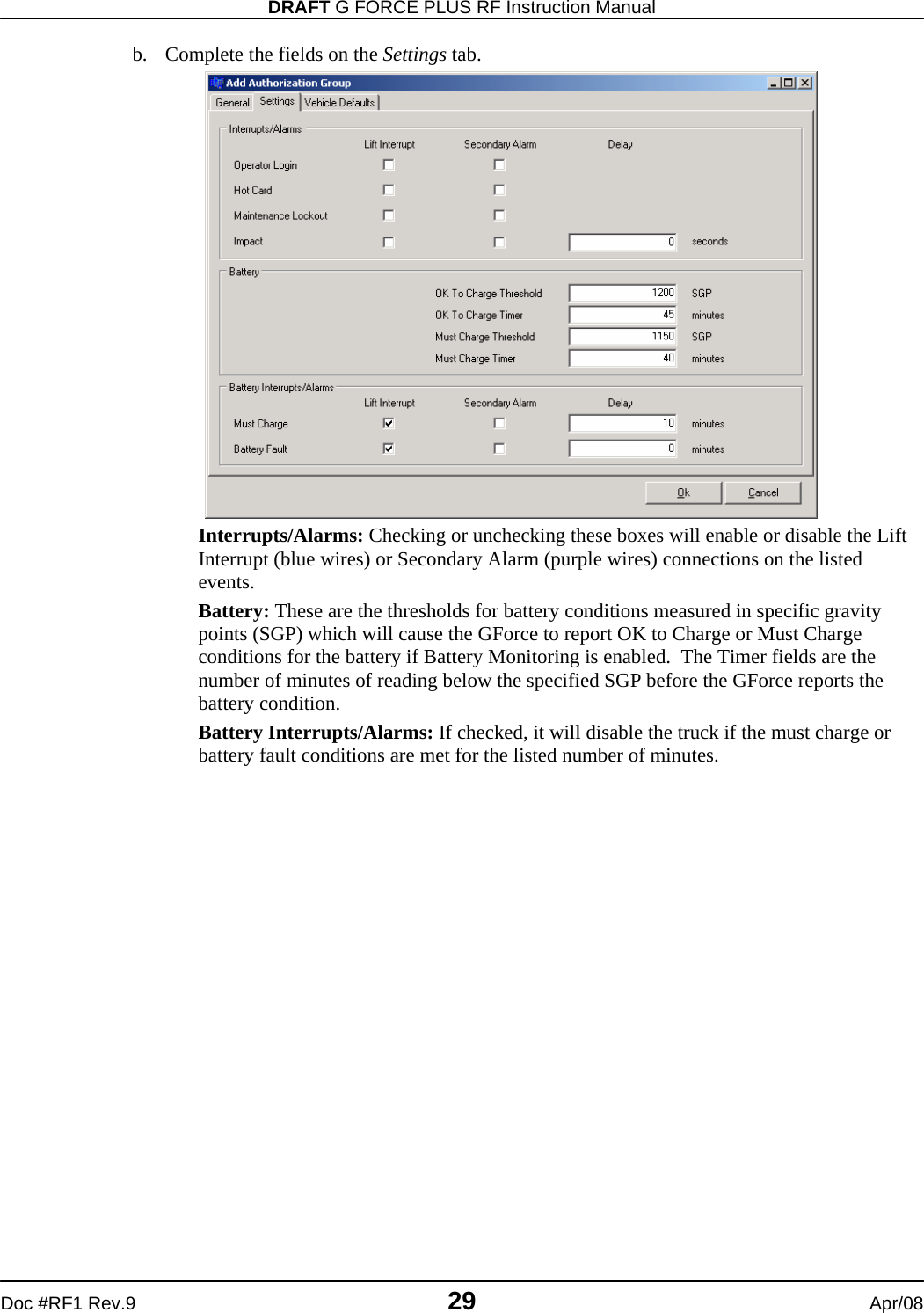
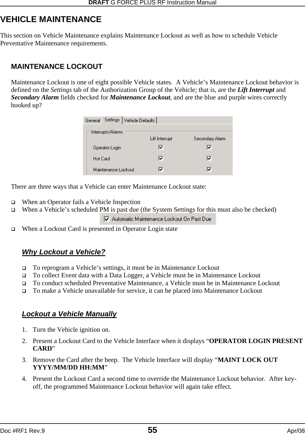
![G FORCE PLUS RF Instruction Manual Apr/08 30 Doc #RF1 Rev.9 c. Complete the fields on the Vehicle Defaults tab. These values will become default values for Vehicles assigned to this Authorization Group. They can be changed for individual trucks if required in the Vehicle Settings tab. Motion Threshold: The sensitivity of the GForce unit to determine if the truck is in motion or not. A lower number means less acceleration is required to get the GForce to sense motion. Motion Interval: The amount of time since the last start, stop, or direction change that the GForce will consider the truck in motion. Battery Nominal Voltage: If battery monitoring is enabled, the voltage that is expected of the battery. Hard/Soft Threshold: The amount of force, expressed in Gs, it takes for the GForce to register a Hard/Soft impact. Hard/Soft Samples: The amount of time (in milliseconds) the hard/soft thresholds need to be exceeded before the truck goes into Impact Alarm. Do not alter these in most circumstances. 3. Click the [OK] button to save the changes. Create a Vehicle Inspection Checklist The Vehicle Inspection Checklist for an Authorization Group is created by selecting from a list of 32 system-defined items, as well as adding up to 8 user-defined (custom) items. Each selected item is displayed on the 2x16-character Vehicle Interface and requires a {Pass} or {Fail} response. 1. Select an Authorization Group from the grid. 2. Click on the Select Inspection List tab at the bottom of the Authorization Group tab. 3. Check the desired system-defined inspection items. These will display on the Vehicle Interface in the order selected from top left to bottom right.](https://usermanual.wiki/BMI-Technologies/RFVI/User-Guide-941196-Page-32.png)
![DRAFT G FORCE PLUS RF Instruction Manual Doc #RF1 Rev.9 31 Apr/08 4. Click the [Save] button to save the Select Inspection List tab changes. 5. Click on the Select Custom List tab at the bottom of the Authorization Group tab. 6. Select up to 8 user-defined inspection items. These will appear on the Vehicle Interface in the order selected from top to bottom after the selected system-defined items. 7. Click the [Save] button to save the Select Custom List tab changes.](https://usermanual.wiki/BMI-Technologies/RFVI/User-Guide-941196-Page-33.png)
![G FORCE PLUS RF Instruction Manual Apr/08 32 Doc #RF1 Rev.9 Edit the Custom Checklist The Custom Checklist allows for an Authorization Group’s Vehicle Inspection Checklist to be customized. The Software can store up to 200 fully editable user-defined items, and is preset with 18 common ones. To modify the list: 3. Select Setup | Custom Check List from the menu. 4. Double-click an item from the list to edit it, or double-click a [Not defined] line to add to the list. 5. Type the text the way you want it to display on the 2x16-character LCD display of the Vehicle Interface.](https://usermanual.wiki/BMI-Technologies/RFVI/User-Guide-941196-Page-34.png)
![DRAFT G FORCE PLUS RF Instruction Manual Doc #RF1 Rev.9 33 Apr/08 6. Click the [OK] button to add the item to the list. 7. Click the [OK] button to save the changes. Edit an Authorization Group 1. Select the Authorization Groups | General tab. 2. Select the Authorization Group you want to edit from the grid. 3. Click the [Edit] button to open the “Edit Authorization Group” window. 4. HINT: Double-click an Authorization Group from the grid to save a step! 5. Change the desired field on the General, Settings or Vehicle Defaults tab. 6. Click the [OK] button to save the changes. NOTE! Changes to the settings of an Authorization Group require all Vehicles in the Authorization Group to be reprogrammed with the Data Logger.](https://usermanual.wiki/BMI-Technologies/RFVI/User-Guide-941196-Page-35.png)
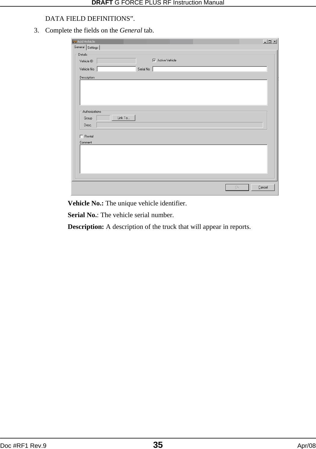
![G FORCE PLUS RF Instruction Manual Apr/08 34 Doc #RF1 Rev.9 Vehicles The details and desired settings of each Vehicle equipped with a Vehicle Monitor must be added to the Fleet Manager Software and linked to one Authorization Group. The Authorization Group to which the Vehicle is assigned is used to determine vehicle access by Operator Card validation, as well as the Inspection Checklist that will display on the Vehicle Interface. Add a Vehicle 1. Select the Vehicles | General tab. 2. Click the [Add] button to open the “Add Vehicle” window. Settings are explained in the section “NOTE! Authorization Groups must be set up before Vehicles and Employees.](https://usermanual.wiki/BMI-Technologies/RFVI/User-Guide-941196-Page-36.png)
![G FORCE PLUS RF Instruction Manual Apr/08 36 Doc #RF1 Rev.9 Click the [Link To…] button to open the “Assign Authorization Group” window. Select an Authorization Group from the grid and click the [OK] button. 4. If the truck requires different settings from the defaults for its Authorization Group, complete the fields on the Settings tab. 5. Click the [OK] button to save the changes. Edit a Vehicle 1. Select the Vehicles | General tab. 2. Select the Vehicle you want to edit from the grid. 3. Click the [Edit] button to open the “Edit Vehicle” window. 4. HINT: Double-click a Vehicle from the grid to save a step! 5. Change the desired field on the General or Settings tab. 6. Click the [OK] button to save the changes. NOTE! Changes to the settings of a Vehicle require the Vehicle Monitor to be reprogrammed with the Data Logger.](https://usermanual.wiki/BMI-Technologies/RFVI/User-Guide-941196-Page-38.png)
![DRAFT G FORCE PLUS RF Instruction Manual Doc #RF1 Rev.9 37 Apr/08 Employees The following Employees must be entered in the Fleet Manager Software. Cards are assigned to each Employee based on role. An Employee may require more than one Card: Employees operating Vehicles for the purpose of materials handling Æ Operator Card Employees responsible for investigating Impact or Hot Card alarms Æ Supervisor Card Employees responsible for Vehicle and battery maintenance Æ Lockout and Unlock Cards Add an Employee 1. Select the Employees | General tab. 2. Click the [Add] button to open the “Add Employee” window. Fields are explained in the section “NOTE! Authorization Groups must be set up before Vehicles and Employees.](https://usermanual.wiki/BMI-Technologies/RFVI/User-Guide-941196-Page-39.png)
![G FORCE PLUS RF Instruction Manual Apr/08 38 Doc #RF1 Rev.9 DATA FIELD DEFINITIONS”. 3. Complete the Add Employee fields and click the [OK] button to save the changes. 4. Define vehicle access rules for the Operator by clicking (see “Define Vehicle Access Rules for an Operator”). 5. All operators must be assigned 1Authorization Group at creation by clicking the Link To… button. 6. Assign a Card to the Employee (see “CARD ASSIGNMENT”). Define Vehicle Access Rules for an Operator Vehicle access rules must be set up for Employees who will be operating Vehicles equipped with Vehicle Monitors. This is done through the assignment of Authorization Groups to the Operator, and in the case of exceptions to this, through the assignment of single Vehicles to the Operator. These assignments are written to an Operator Card, and when presented to a Vehicle Interface, it is determined if there is a match between the Operator Card and the Authorization Group to which a Vehicle belongs (or a match to the Vehicle itself in the case of Single Vehicle assignments). 1. Select the Employees tab. 2. Select the desired Employee from the grid. 3. Assign Authorization Groups to the Operator.](https://usermanual.wiki/BMI-Technologies/RFVI/User-Guide-941196-Page-40.png)
![DRAFT G FORCE PLUS RF Instruction Manual Doc #RF1 Rev.9 39 Apr/08 a. Click the Employees | Assign Authorization Groups tab. b. Click the [Add] button to open the “Assign Authorization Group” window. c. Select an Authorization Group from the grid. d. Click the [OK] button to save the addition. e. HINT: Double-click an Authorization Group to save a step! 4. Repeat until all Authorization Groups for the Operator are shown on the Employees | Assign Authorization Groups tab. 5. Assign Single Vehicles to the Operator where Authorization Group assignments do not apply (for example, to keep an Operator-in-training off new vehicles). a. Click the Employees | Assign Single Vehicles tab.](https://usermanual.wiki/BMI-Technologies/RFVI/User-Guide-941196-Page-41.png)
![G FORCE PLUS RF Instruction Manual Apr/08 40 Doc #RF1 Rev.9 b. Click the [Add] button to open the “Assign Single Vehicles” window. c. Select a Vehicle from the grid. d. Click the [OK] button to save the addition. e. HINT: Double-click a Vehicle to save a step! 6. Repeat until all Vehicles for the Operator are shown on the Employees | Assign Single Vehicles tab. 7. Delete Authorization Group or Single Vehicle assignments by using the [Delete] button on the “Assign Authorization Groups” and “Assign Single Vehicles” windows. Edit an Employee 1. Select the Employees tab. 2. Change the Employee’s general details if required. a. Select the Employee you want to edit from the grid. b. Click the [Edit] button to open the “Edit Employee” window. c. HINT: Double-click an Employee from the grid to save a step! d. Change the desired field. e. Click the [OK] button to save the changes. 3. Change the Employee’s Authorization Group assignments if required. a. Select the Employee you want to edit from the grid. b. Select the Employees | Assign Authorization Groups tab. c. Click the [Add] or [Delete] button to add or delete Authorization Groups until the Employees | Assign Authorization Groups tab shows the desired Authorization Group assignments. 4. Change the Employee’s single Vehicle assignments if required. a. Select the Employee you want to edit from the grid. b. Select the Employees | Assign Single Vehicles tab. c. Click the [Add] or [Delete] button to add or delete Vehicles until the Employees | Assign Single Vehicles tab shows the desired Vehicle assignments. 5. Update the Employee’s Operator Card if required (see CARD ASSIGNMENT). Transceivers Data is communicated from an RF Vehicle Monitor-equipped Vehicle to the Fleet Manager Software by way of a network of RF Transceivers. The RF Host Transceiver is physically connected to the PC running the Fleet Manager Software and other RF Transceivers (Zone Transceivers) are each placed within range of the Host Transceiver. While the Fleet Manager Software automatically detects the presence of the RF Transceivers once the Host Transceiver is connected to the PC, their identification within the Software can be customized for display on the Fleet Status tab if desired. NOTE! Recertification Date and vehicle access rule changes for Operators require the Employee’s Operator Card to be updated.](https://usermanual.wiki/BMI-Technologies/RFVI/User-Guide-941196-Page-42.png)
![DRAFT G FORCE PLUS RF Instruction Manual Doc #RF1 Rev.9 41 Apr/08 1. Select Setup | Zone Description… from the menu to open the “Zone Description Entry” window. The Zone Description defaults are “Zone # 0”, “Zone # 1”, “Zone # 2”, etc. 2. Click on the desired Description to highlight the text. 3. Rename the Zone Description to match the physical location of the selected Zone Transceiver. Each Zone Transceiver is labeled with its factory-assigned Zone Number. 4. Click the [OK] button to save the changes. 5. It is recommended to name the Host Transceiver (Zone # 0) as “Host”. 6. The new Description will be used to identify the Last Zone for each Vehicle on the Fleet Status tab. CARD ASSIGNMENT After Employees are entered in the Fleet Manager Software, they are assigned Cards that are read by the Vehicle Interface of each Vehicle. Cards are assigned to each Employee based on the role of the Employee. An Employee may require more than one Card: Employees operating Vehicles for the purpose of materials handling Æ Operator Card Employees responsible for investigating Impact or Hot Card alarms Æ Supervisor Card Employees responsible for Vehicle and battery maintenance Æ Lockout and Unlock Cards Set a Card Expiry Date NOTE! Employees who will be assigned Operator Cards must have vehicle access rules defined.](https://usermanual.wiki/BMI-Technologies/RFVI/User-Guide-941196-Page-43.png)
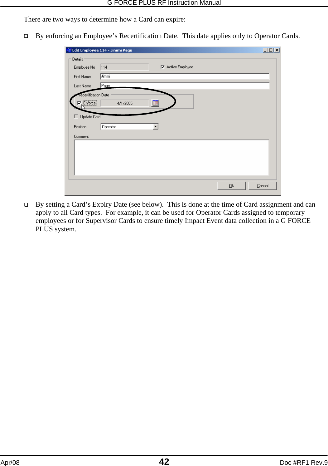
![DRAFT G FORCE PLUS RF Instruction Manual Doc #RF1 Rev.9 43 Apr/08 Assign a Card Follow steps 2 to 9 for initial Card assignment, as well as for updating Cards or reassigning them to new Employees. 1. Select the Cards tab. 2. Place a Card on the Software Interface. 3. Click the [Write] button to open the “Write to Card” window. The Software recognizes and displays the Card serial number and type, and the Employee if the Card is being updated. 4. Enter a Card Expiry Date if required (for example, for temporary Employees). Setting a Card’s Expiry Date renders it unusable on or after that date. This applies to all Card types. a. Check the Enforce checkbox. b. Click the [] button (Calendar) to select the date. c. Click the [OK] button to close the “Select Date” window. 5. Select the Employee to assign the Card to. a. Click the [Link To…] button to open the “Select Employee” window.](https://usermanual.wiki/BMI-Technologies/RFVI/User-Guide-941196-Page-45.png)
![G FORCE PLUS RF Instruction Manual Apr/08 44 Doc #RF1 Rev.9 b. Select an Employee from the grid. c. Click the [OK] button to save the change. d. HINT: Double-click an Employee to save a step! 6. Click the [Program Card] button. The mouse-pointer will turn into an hourglass ( ) while the details are being written to the Card. 7. Click the [OK] button to close the window that indicates the Card has been updated. 8. Remove the Card from the Software Interface and give it to the Employee. VEHICLE MONITOR Each Vehicle that is added to the Fleet Manager Software is assigned a system-defined identification number (ID). This ID is different than the company-assigned identification number (Vehicle No). This ID uniquely identifies the Vehicle within the system and must be programmed to the Vehicle Monitor to draw a connection between it and its entry in the Software. In addition, settings for each Vehicle are maintained in the Software. These settings determine a Vehicle’s unique behavior and must also be programmed from the Software to the Vehicle Monitor. The Data Logger is used for both these programming tasks. Initialize a Vehicle Monitor The first time a Vehicle Monitor is installed on a Vehicle, it needs to be initialized. This is when both the Vehicle ID and settings from the Software are programmed. The Data Logger can initialize up to 9 (nine) Vehicle Monitors at a time; it has 9 (nine) memory slots for Vehicle IDs and 9 (nine) memory slots for Vehicle settings. 1. Get the Vehicle ID for the selected Vehicle. a. Press {Enter} on the Data Logger to start it. b. Press {2} when the Data Logger displays “Action?(1-9)”. The Data Logger will display “Action?(1-9) Get Vehicle ID” c. Press {Enter} to accept the choice. The Data Logger will display “Select Slot:” d. Press {1} to select slot #1. The Data Logger will display “Select Slot: 1 Free” e. Press {Enter} to accept the choice. The Data Logger will display “Select Slot: 1 Slot 1 Ready” NOTE! Don’t throw a Card away if an Employee quits. Reuse it by linking a new Employee to it.](https://usermanual.wiki/BMI-Technologies/RFVI/User-Guide-941196-Page-46.png)
![DRAFT G FORCE PLUS RF Instruction Manual Doc #RF1 Rev.9 45 Apr/08 f. Present the Data Logger to the Software Interface. g. Select the desired Vehicle from the Vehicles tab of the Fleet Manager Software and click the [Veh ID] button. The status bar at the bottom left of the Software will provide progress information (“Programming vehicle id…”). When it finishes, the Data Logger will display “All Data Saved”. h. This window will appear. If you wish to confirm the ID was programmed, on the Data Logger press {Cancel}, then press {5}, {Enter}, {1}, {Enter} and present the Data Logger to the Software Interface, then click the [Yes] button. To skip this step, press [No] i. If you chose to confirm the ID, this window will appear. The Data Logger will display “All Data Prog’d”. j. Remove the Data Logger from the Software Interface and press {Cancel}. The Data Logger will display “Action?(1-9)” 2. Record the memory slot used for the selected Vehicle. 3. Get the Vehicle settings for the selected Vehicle. a. Press {Enter} to start the Data Logger. b. Press {3} when the Data Logger displays “Action?(1-9)”. The Data Logger will display “Action?(1-9) Get Veh Settings”](https://usermanual.wiki/BMI-Technologies/RFVI/User-Guide-941196-Page-47.png)
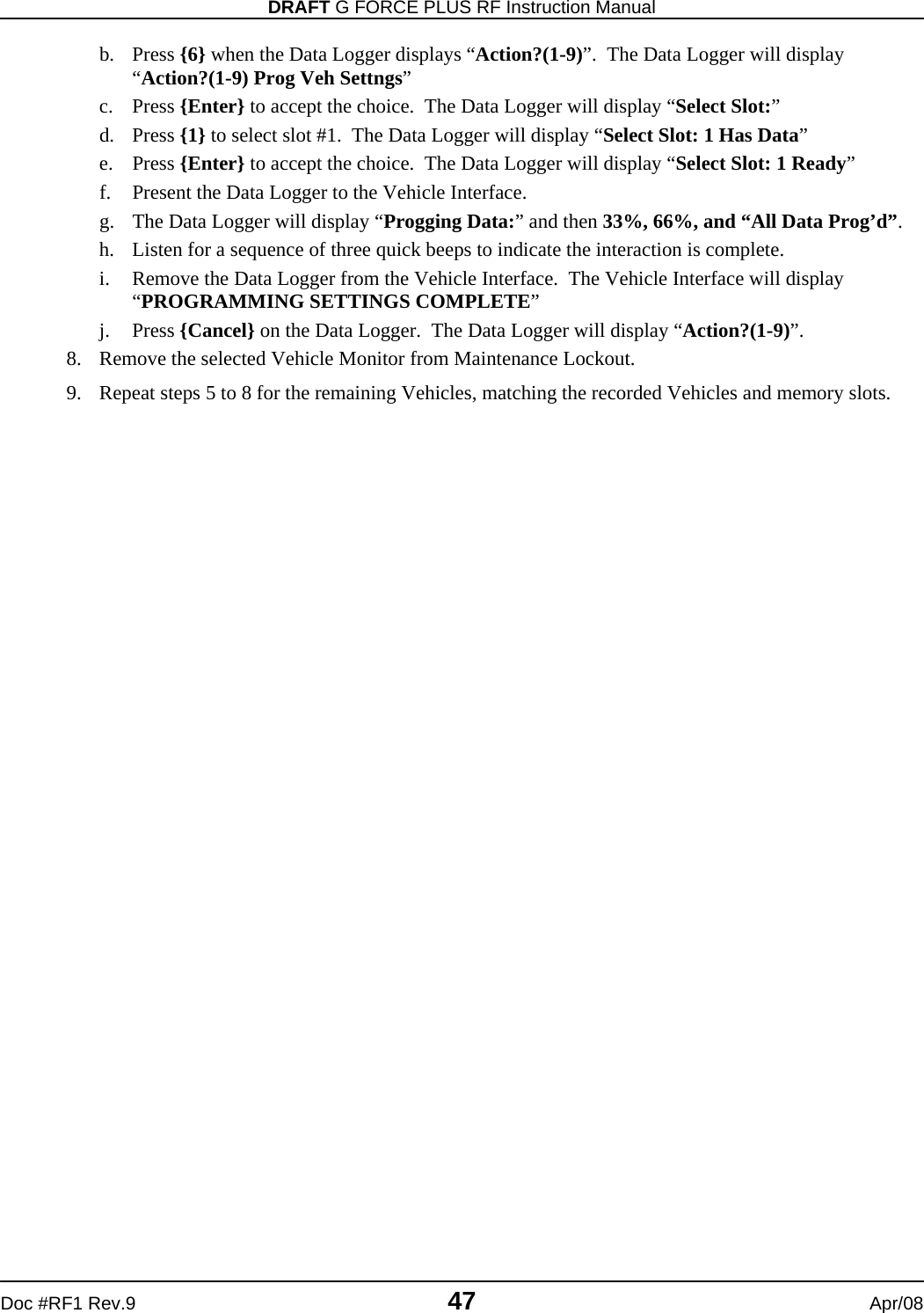
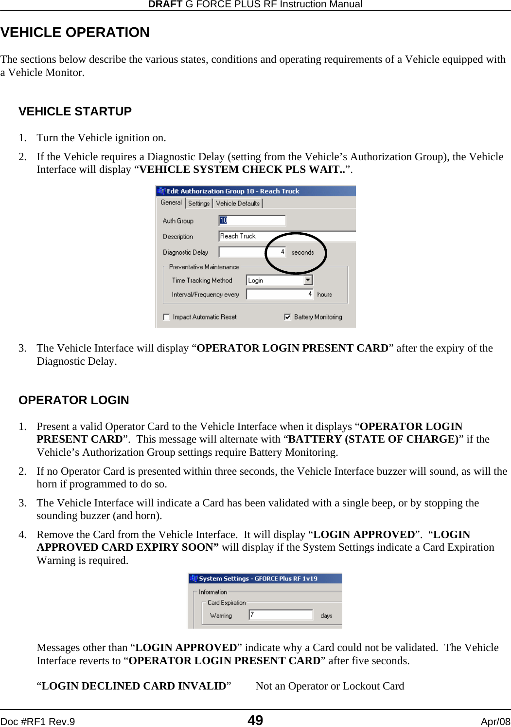
![G FORCE PLUS RF Instruction Manual Apr/08 46 Doc #RF1 Rev.9 c. Press {Enter} to accept the choice. The Data Logger will display “Select Slot:” d. Press {1} to select slot #1. The Data Logger will display “Select Slot: 1 Free” e. Press {Enter} to accept the choice. The Data Logger will display “Select Slot: 1 Slot 1 Ready” f. Present the Data Logger to the Software Interface. g. Select the same Vehicle from the Vehicle tab of the Fleet Manager Software and click the [Veh Settings] button. The status bar at the bottom left of the Software will provide progress information (“Programming vehicle parameters…” etc). h. When it is complete, this window will appear. If you wish to confirm the Settings were programmed, on the Data Logger press {Cancel}, then press {6}, {Enter}, {1}, {Enter} and present the Data Logger to the Software Interface, then click the [Yes] button. To skip this step, click the [No] button. i. If you chose to confirm the settings, this window will appear. Click the [OK] button to confirm completion. j. Remove the Data Logger from the Software Interface and press {Cancel}. The Data Logger will display “Action?(1-9)” 4. Repeat steps 1 to 3 for up to 8 (eight) more Vehicles, working through memory slots 2 to 9 and recording the memory slot used for each Vehicle. 5. Place the Vehicle from memory slot #1 into Maintenance Lockout. 6. Program the Vehicle ID to the Vehicle Monitor. a. Press {Enter} to start the Data Logger. b. Press {5} when the Data Logger displays “Action?(1-9)”. The Data Logger will display “Action?(1-9) Prog Veh ID” c. Press {Enter} to accept the choice. The Data Logger will display “Select Slot:” d. Press {1} to select slot #1. The Data Logger will display “Select Slot: 1 Has Data” e. Press {Enter} to accept the choice. The Data Logger will display “Select Slot: 1 Ready” f. Present the Data Logger to the Vehicle Interface. g. Listen for a sequence of three quick beeps to indicate the interaction is complete. h. Remove the Data Logger from the Vehicle Interface. The Vehicle Interface will display “VEHICLE ID UPDATED”. i. Press {Cancel} on the Data Logger. The Data Logger will display “Action?(1-9)”. 7. Program the Vehicle settings to the Vehicle Monitor. a. Press {Enter} to start the Data Logger.](https://usermanual.wiki/BMI-Technologies/RFVI/User-Guide-941196-Page-48.png)
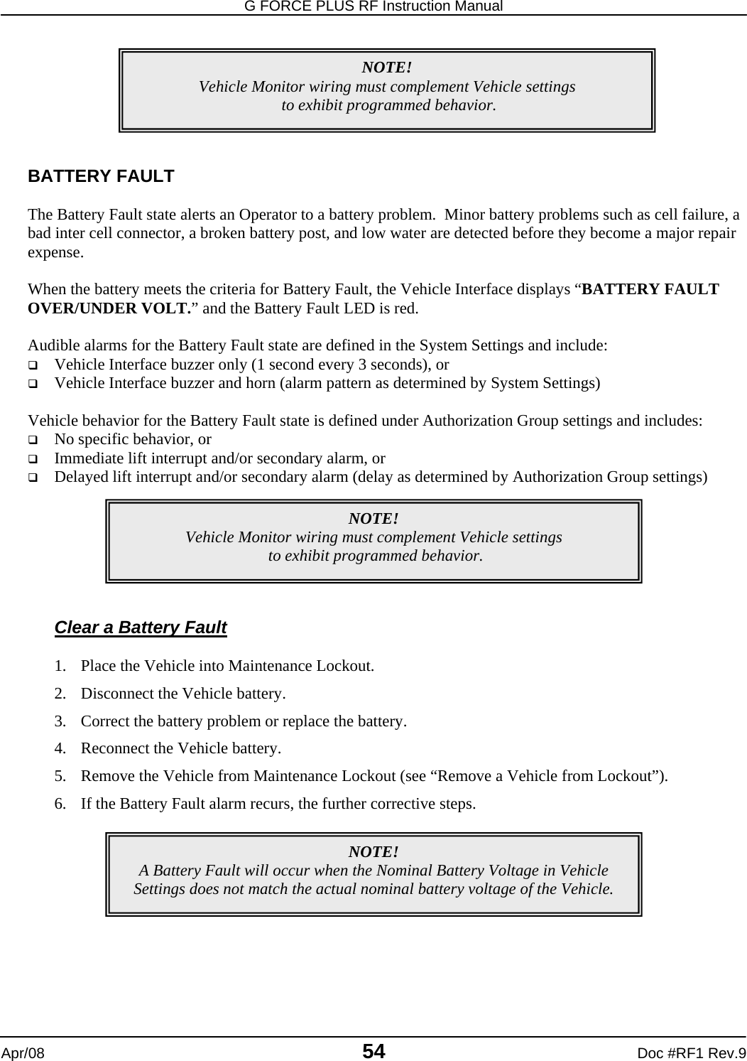
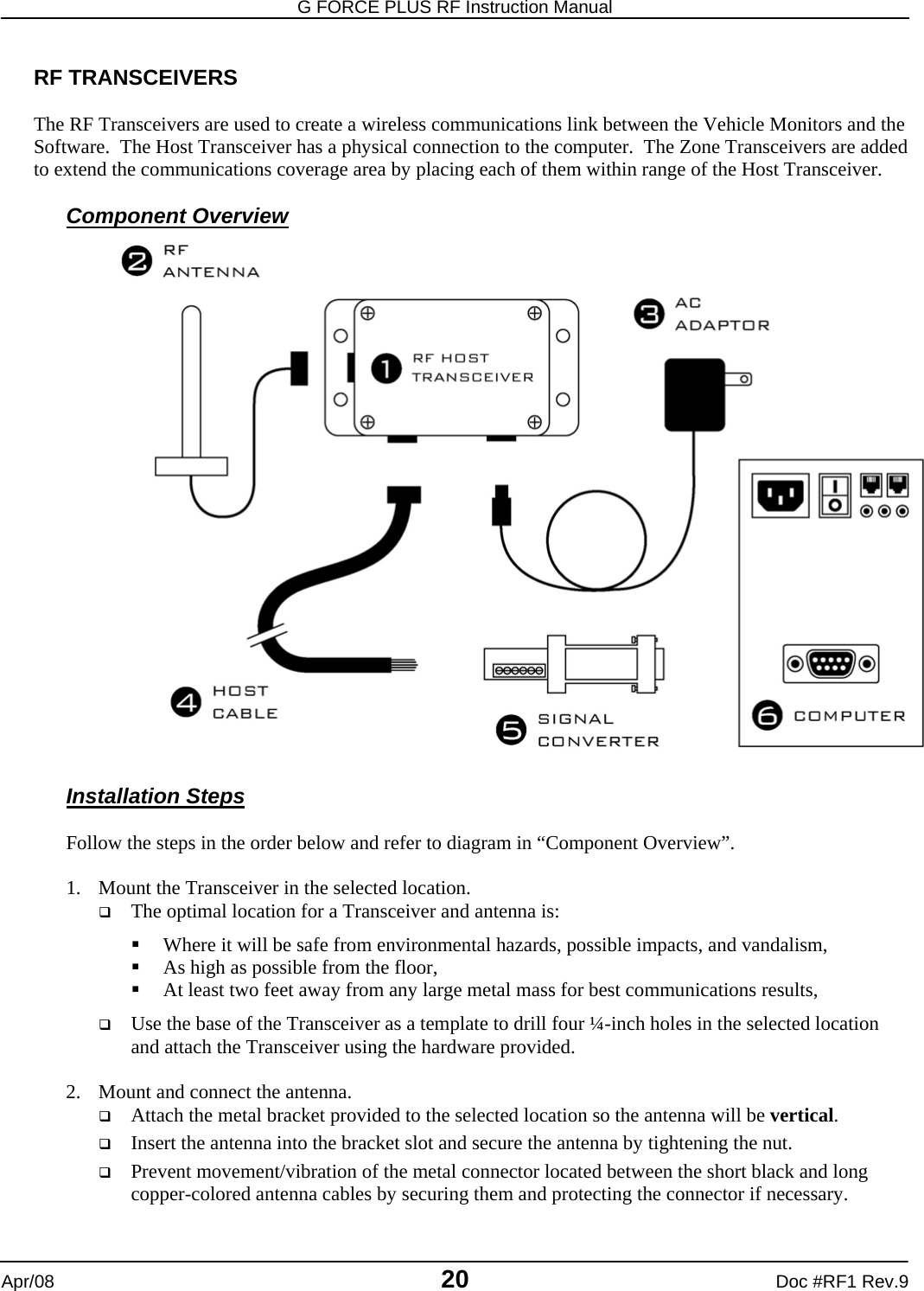
![G FORCE PLUS RF Instruction Manual Apr/08 56 Doc #RF1 Rev.9 Override Maintenance Lockout Behavior 1. Present a Lockout Card to the Vehicle Interface when it displays “MAINT LOCK OUT YYYY/MM/DD HH:MM”. 2. Remove the Card after the beep. The Vehicle Interface will display “HOURMETER XXXXXH” “PM DUE IN: XXXXXH”. 3. Programmed Maintenance Lockout behavior (i.e. lift interrupt, etc.) will no longer exhibit. 4. After key-off, the programmed Maintenance Lockout behavior will again take effect. Remove a Vehicle from Lockout 1. Turn the Vehicle ignition on. 2. Present an Unlock Card to the Vehicle Interface when it displays “MAINT LOCK OUT YYYY/MM/DD HH:MM”. 3. Remove the Card after the beep. The Vehicle Interface will display “SCHEDULED PM COMPLETE? YES/NO”. 4. Press {No} on the Vehicle Interface unless the Lockout was to conduct scheduled PM. The Vehicle Interface will display “OPERATOR LOGIN PRESENT CARD”. MAINTENANCE WORK ORDERS It is possible to keep track of Vehicle maintenance by entering Maintenance Work Orders into the Software. The reason for each Work Order is categorized as Impact, Scheduled PM, Failed Inspection or Other. This allows the Software to report maintenance costs by these reasons. Add a Work Order 1. Select the Vehicles tab. 2. Highlight (click) the Vehicle you want to add a Work Order for. 3. Click the Maintenance Work Orders tab at the bottom of the Vehicles tab. 4. Click the [Add] button to open the “Add Maintenance Work Order” window. 5. Complete the fields on the Work Order as per the field descriptions below. Reference No Enter a Work Order number, or enter the reference number from the paper copy of the shop Work Order. Reason Select a reason the work was done: (1) Impact, (2) Scheduled PM, (3) Failed Inspection, (4) Other. Service Date Click the [] button (Calendar) to select the date of the Work Order. Service Hours Enter the Hour Meter reading of the Vehicle at the time the work was completed.](https://usermanual.wiki/BMI-Technologies/RFVI/User-Guide-941196-Page-58.png)
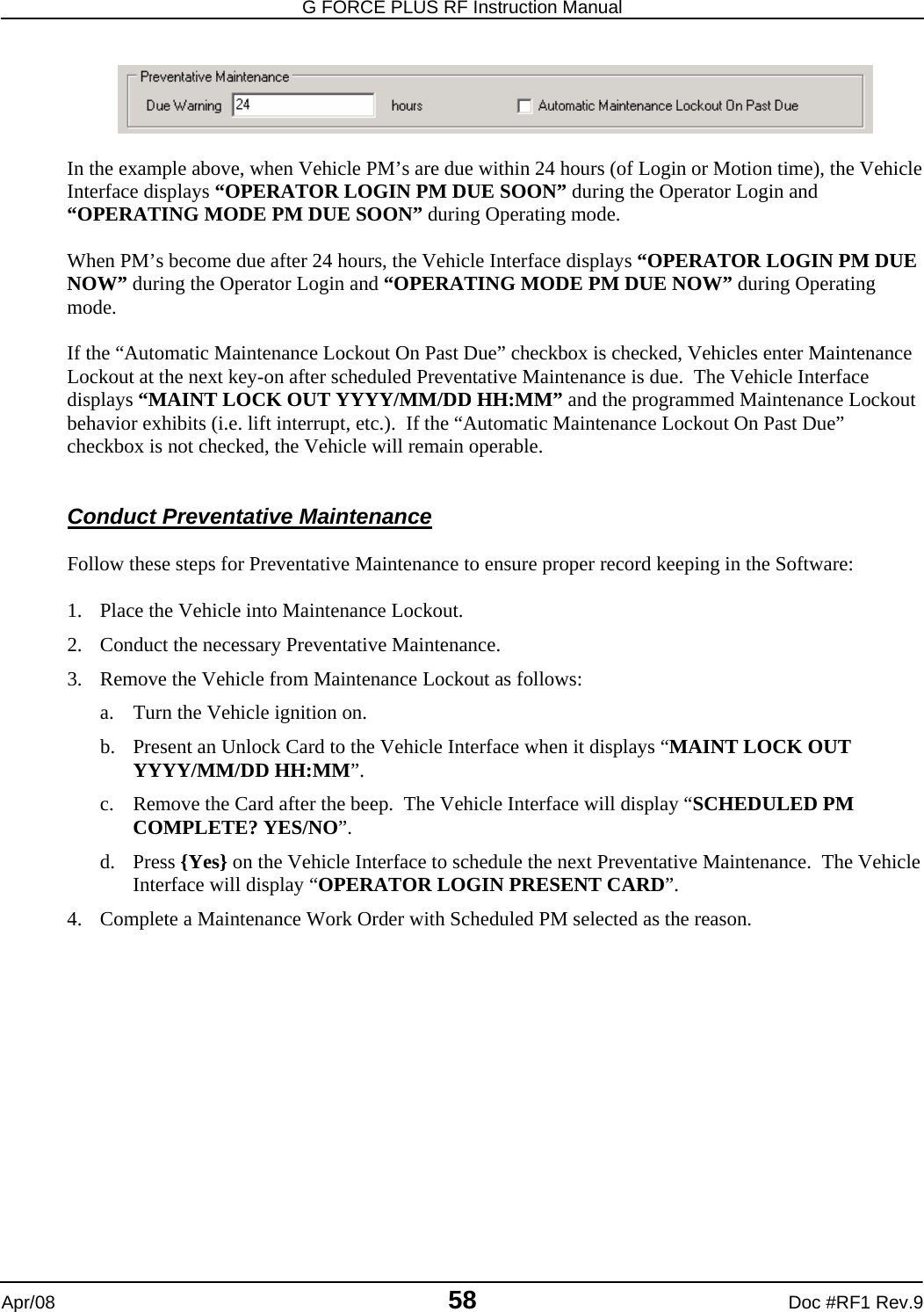
![DRAFT G FORCE PLUS RF Instruction Manual Doc #RF1 Rev.9 57 Apr/08 Impact Date and Employee If the Work Order reason is Impact or Failed Inspection, click the [Link To…] button to select the event that caused the work to be completed. Service Technician Click the [Link To…] button to select the Service Technician who completed the work. Costing Enter the Parts and Labor Costs of the work completed. Parts Description Enter a description of the Parts used to complete the work. Comment Enter a Comment. 6. Click the [OK] button to save the changes. Edit a Work Order 1. Select the Vehicles tab. 2. Highlight (click) the Vehicle you want to add a Work Order for. 3. Click the Maintenance Work Orders tab at the bottom of the Vehicles tab. 4. Highlight (click) the Work Order you want to edit. 5. Click the [Edit] button to open the “Edit Maintenance Work Order” window. 6. HINT: Double-click a Work Order from the grid to save a step! 7. Edit the fields as required. 8. Click the [OK] button to save the changes. PREVENTATIVE MAINTENANCE Vehicle Monitors can be scheduled to advise when regular Preventative Maintenance checks are required. The Preventative Maintenance settings for each Authorization Group determine how often the checks are required and how time is calculated (i.e. Login, Motion) for all Vehicles belonging to the Authorization Group. In the example above, when a Vehicle is initialized, its first scheduled Preventative Maintenance will be after 250 hours of Login time. After that, Preventative Maintenance checks are scheduled for 250 hours from the Current Hour Meter reading. For example, if the PM is completed at 262 hours, the next PM will be required at 512 hours. PM Due Notification The Preventative Maintenance System Settings determine if there is a warning that Preventative Maintenance is due soon, as well as Vehicle behavior once Preventative Maintenance is due. These settings apply to all Vehicles in the system.](https://usermanual.wiki/BMI-Technologies/RFVI/User-Guide-941196-Page-59.png)
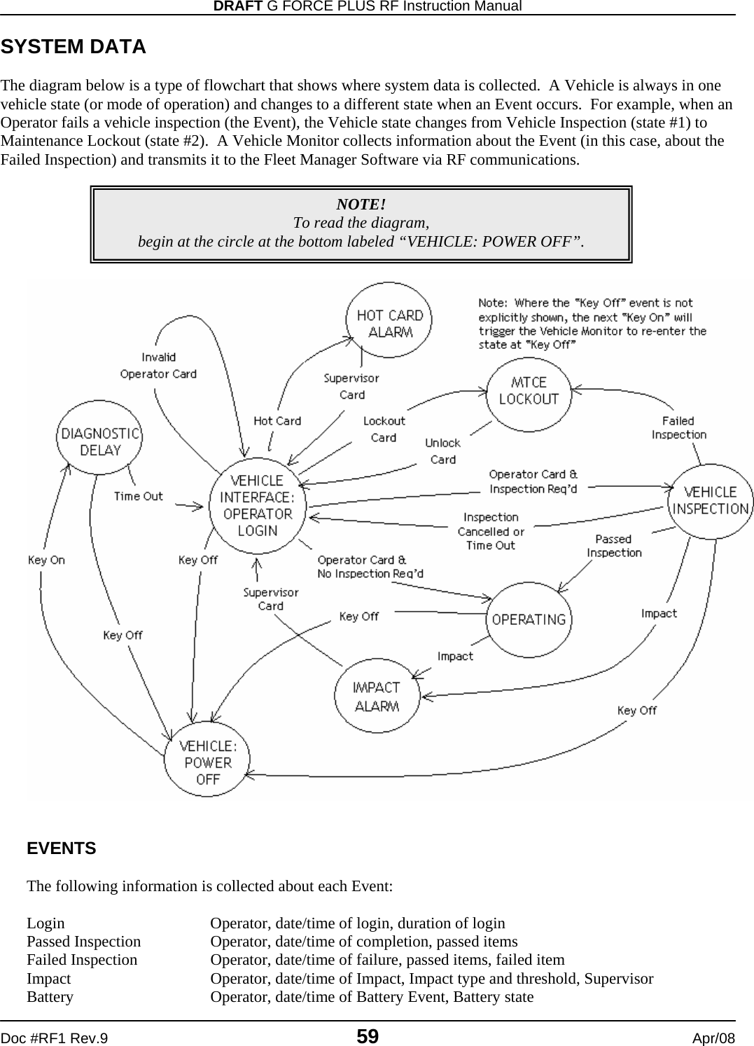
![DRAFT G FORCE PLUS RF Instruction Manual Doc #RF1 Rev.9 61 Apr/08 3. Press {4} when the Data Logger displays “Action?(1-9)”. The Data Logger will display “Action?(1-9) Events from Veh” 4. Press {Enter} to accept the choice. The Data Logger will display “Ready for Events XXXX/1500” 5. Present the Data Logger to the Vehicle Interface. 6. Listen for a sequence of three quick beeps to indicate the interaction is complete. 7. Remove the Data Logger from the Vehicle Interface. The Vehicle Interface will display “MAINT LOCK OUT YYYY/MM/DD HH:MM” 8. Press {Cancel} on the Data Logger. The Data Logger will display “Action?(1-9)” 9. Remove the Vehicle from Maintenance Lockout. DOWNLOAD DATA TO THE SOFTWARE MANUALLY 1. Press {Enter} to start the Data Logger. 2. Press {1} when the Data Logger displays “Action?(1-9)”. The Data Logger will display “Action?(1-9) Events to PC” 3. Press {Enter} to accept the choice. The Data Logger will display “Ready for PC” 4. Present the Data Logger to the Software Interface. 5. Start the Fleet Manager Software (optionally select the Events tab). 6. Select Download | Events | Data Logger from the menu. The status bar at the bottom left of the Software will provide progress information. 7. Click the [OK] button to confirm completion. 8. Remove the Data Logger from the Software Interface. The Data Logger will display “No Events!” 9. Press {Cancel} on the Data Logger. The Data Logger will display “Action?(1-9)” NOTE! If the Data Logger is removed from the Vehicle Interface too soon, six quick beeps will sound. Return the Data Logger to the Vehicle Interface to begin data collection again. No data has been lost.](https://usermanual.wiki/BMI-Technologies/RFVI/User-Guide-941196-Page-63.png)
![G FORCE PLUS RF Instruction Manual Apr/08 62 Doc #RF1 Rev.9 ADD A COMMENT ABOUT AN IMPACT A Supervisor’s comments about an Impact can be added to the Software. The comments are included on the Impact Reports. 1. Select the Events | Impact tab. 2. Highlight (click) the Impact you want to add a Comment for. 3. Click the [Impact Comment] button to open the “Impact Comment” window. 4. Enter the comment in the Comment field to a maximum of 255 characters. The Software will not allow entry of more than 255 characters. 5. Click the [OK] button to save the changes. 6. To edit an Impact Comment, repeat steps 2 to 5, making changes to the text as required.](https://usermanual.wiki/BMI-Technologies/RFVI/User-Guide-941196-Page-64.png)
![DRAFT G FORCE PLUS RF Instruction Manual Doc #RF1 Rev.9 63 Apr/08 REPORTS The Software provides several useful reports that can be filtered, using a “Report Selection” window, to display ranges of data and dates. Clicking the [] button (Ellipses) opens a window that filters a report by the one selection made. Most reports are accessible from the Reports menu. ORGANIZATION GROUPS Organization Groups are optional, but if used, there is no limit to their use. Organization Groups are for additional classification of Employees and Vehicles to provide greater report filtering (i.e. they do not limit Operator access to Vehicles like Authorization Groups do). The filtering selected in the “Report Selection” window below will generate an Impact Report ordered by Employee for impacts between December 1 and December 31, 2005. It will only include impacts for Employees belonging to the Probation Organization Group.](https://usermanual.wiki/BMI-Technologies/RFVI/User-Guide-941196-Page-65.png)
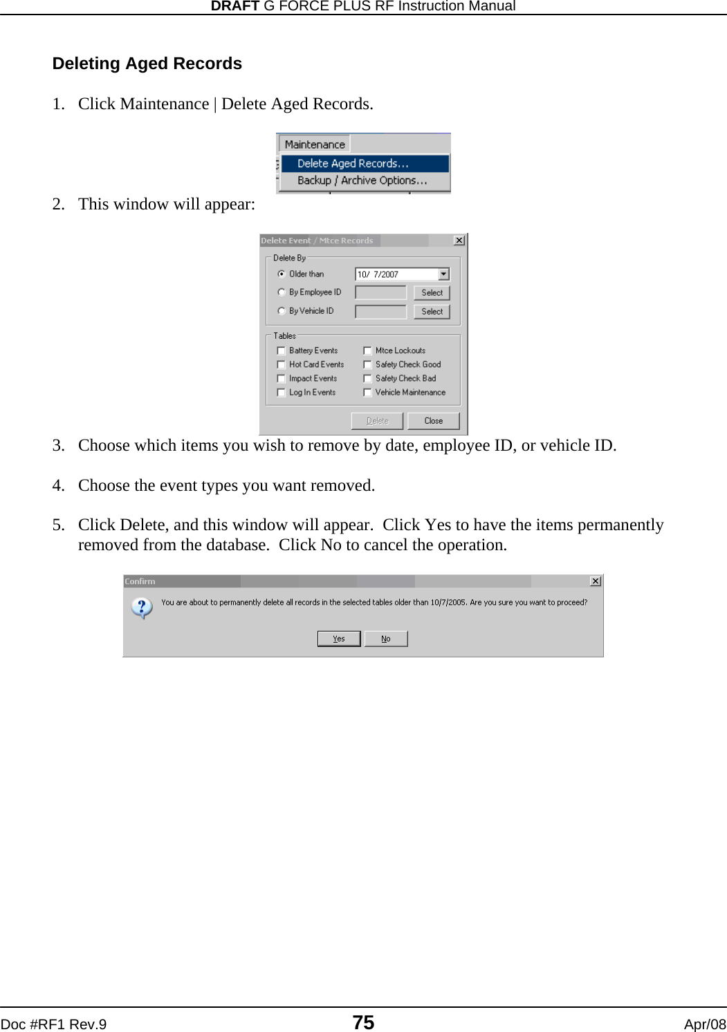
![G FORCE PLUS RF Instruction Manual Apr/08 64 Doc #RF1 Rev.9 Add an Organization Group 1. Select the Organization Groups tab. 2. Click the [Add] button to open the “Add Organization Group” window. 3. Enter an Organization Group description in the Description field. 4. Click the [OK] button to save the change. The added Group will be displayed in the Organization Groups tab. Delete an Organization Group 1. Select the Organization Groups tab. 2. Select the Organization Group you want to delete from the grid. 3. Click the [Delete] button to open the “Confirm” window. 4. Click the [Yes] button to confirm the deletion of the Organization Group. The deleted Group will be removed from the Organization Groups tab.](https://usermanual.wiki/BMI-Technologies/RFVI/User-Guide-941196-Page-66.png)
![DRAFT G FORCE PLUS RF Instruction Manual Doc #RF1 Rev.9 65 Apr/08 Assign an Organization Group After the desired Organization Groups are created, Employees and/or Vehicles are assigned the Organization Groups. 1. Select the Employees or Vehicles tab, as required. 2. Select the desired Employee or Vehicle from the grid. 3. Click the Assign Organization Groups tab. 4. Assign Organization Groups to the Employee or Vehicle. a. Click the [Add] button to open the “Assign Organization Group” window. b. Select an Organization Group from the grid. c. Click the [OK] button to save the addition. d. HINT: Double-click an Organization Group to save a step! e. Repeat steps a. to d. until all Organization Groups for the Employee or Vehicle are shown in the Assign Organization Groups tab. 5. Repeat steps 2 to 4 until all Organization Groups assignments for Employees or Vehicles are done. Organization Group Examples Create a Probation group to compare Impact or Productivity Reports for all Employees and for Probation Employees Create a Night Shift group to compare Impact or Productivity Reports for all Employees and for Night Shift Employees Create an Outside group to compare Impact or Productivity Reports for all Vehicles and for Outside Vehicles](https://usermanual.wiki/BMI-Technologies/RFVI/User-Guide-941196-Page-67.png)
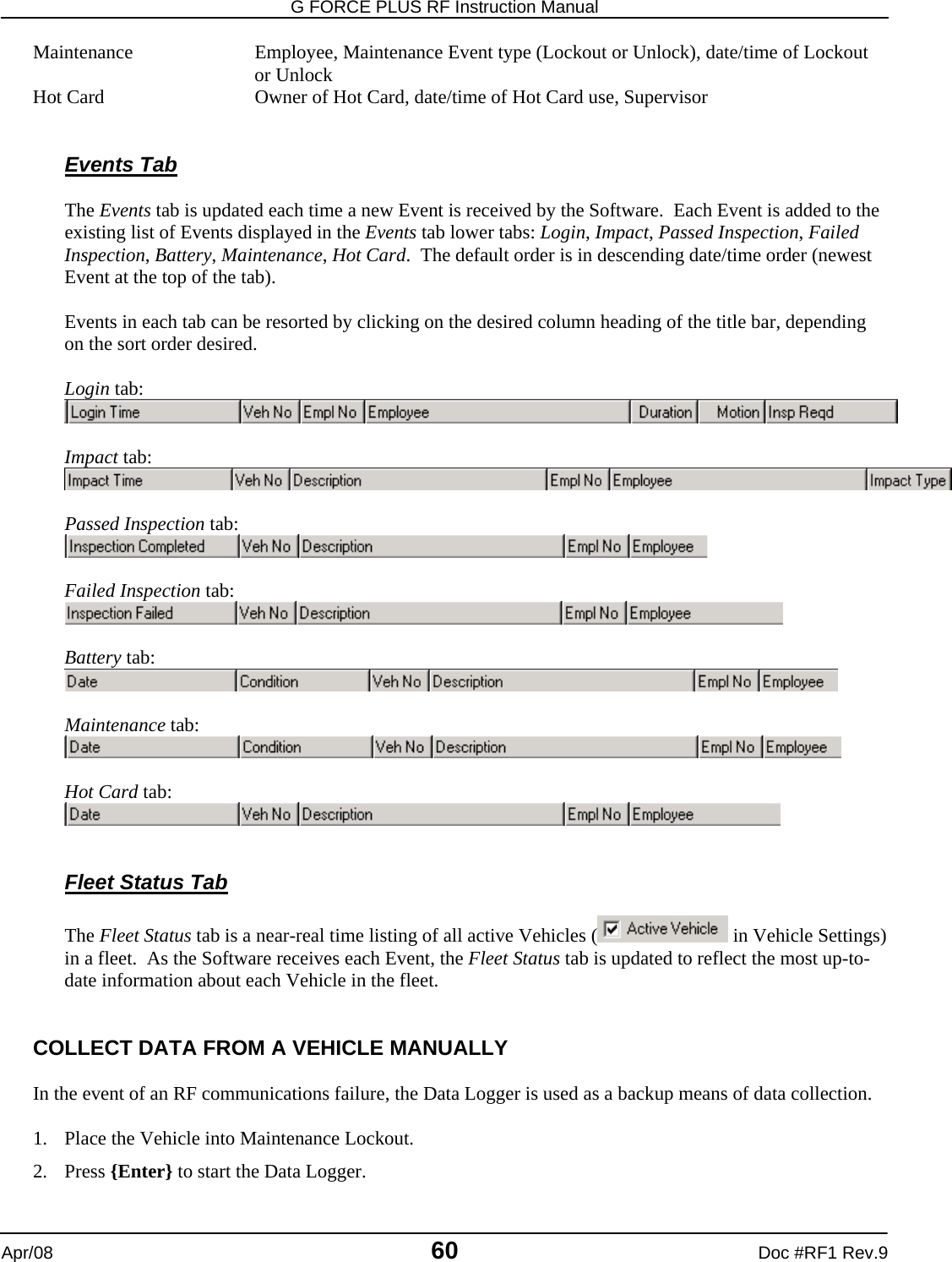
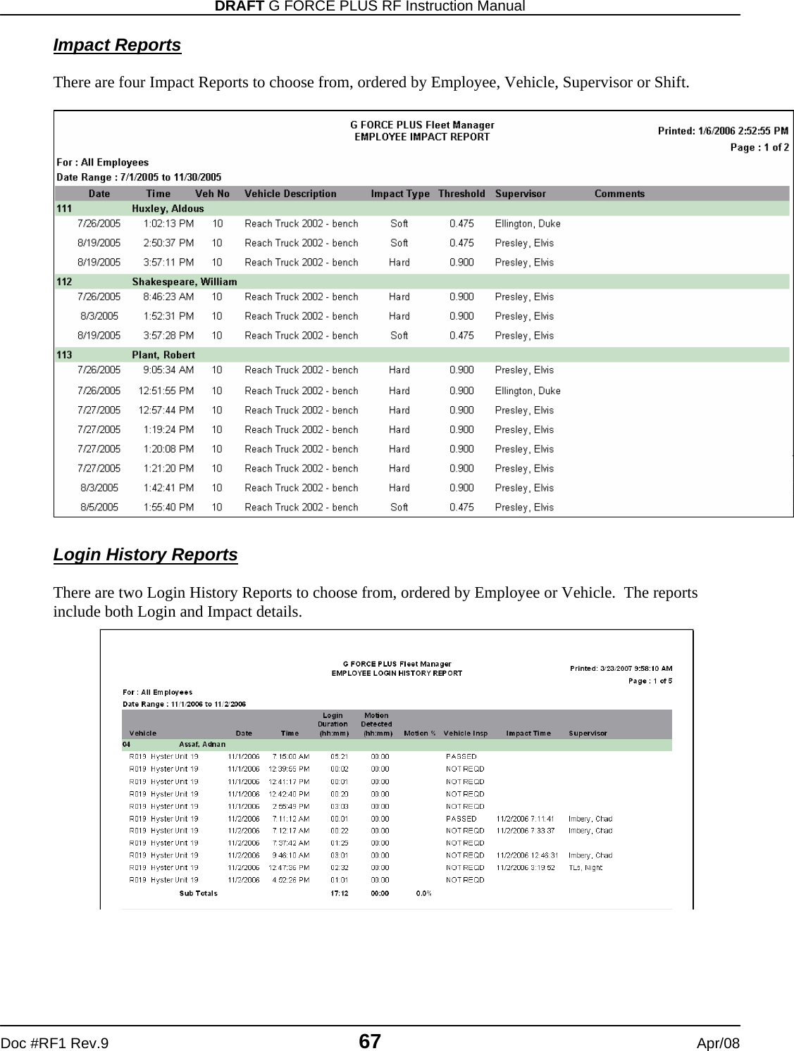
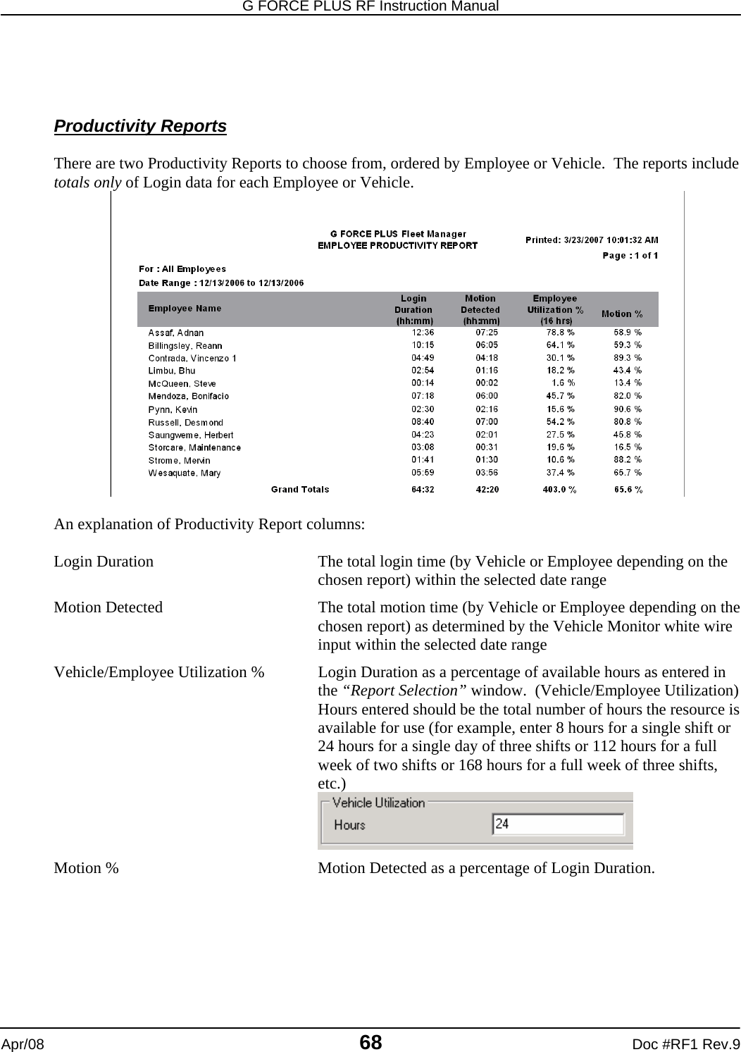
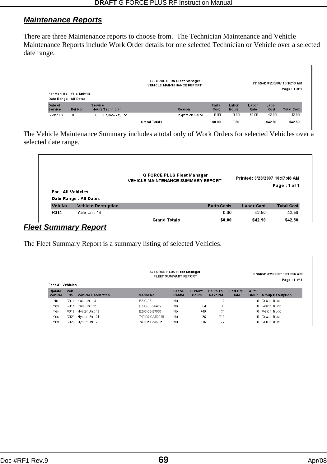
![G FORCE PLUS RF Instruction Manual Apr/08 66 Doc #RF1 Rev.9 SAMPLE REPORTS The following reports are available in the Software: Vehicle Inspection Reports 1. Select the Events tab. 2. Select the Passed Inspection or Failed Inspection tab at the bottom of the Events tab. 3. Double-click the desired Inspection Event to generate the report in a “Print Preview” window. 4. Click the [] button (Print) to print the report or click [Close].](https://usermanual.wiki/BMI-Technologies/RFVI/User-Guide-941196-Page-68.png)
![G FORCE PLUS RF Instruction Manual Apr/08 70 Doc #RF1 Rev.9 Card Status Report The Card Status Report is a summary listing of all Cards in ascending Recertification Date order. EXPORTING REPORT DATA Any report data can be exported to a .CSV file for use outside the Software (i.e. in Microsoft® Excel). 1. Generate the desired report in the “Print Preview” window. 2. Click the [] button (Save Report) to open the “Save report” window. 3. Select the desired file destination from the Save in: field. 4. Enter a meaningful file name in the File name: field. 5. Select “Comma Separated (*.CSV)” from the Save as type: field. 6. Click the [Save] button to save the file to the chosen location.](https://usermanual.wiki/BMI-Technologies/RFVI/User-Guide-941196-Page-72.png)
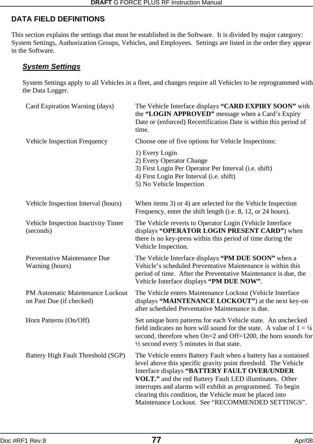
![DRAFT G FORCE PLUS RF Instruction Manual Doc #RF1 Rev.9 71 Apr/08 ADDITIONAL SYSTEM FEATURES PASSWORD While a password is not required, it is recommended to prevent unauthorized access to the Fleet Manager data. Password rules are as follows: Case-sensitive, meaning “goldfish”, “Goldfish”, and “GOLDFISH” are three different passwords Must be at least 6 characters long, and no more than 14 characters long Allowable characters can be from the full keyboard set, including upper and lower case A-Z, 0-9, and special characters such as: !@#$%^&*()_+{}<>? A space is also a valid character but cannot be the first or last position It is best to mix letters, numbers and characters Avoid easily cracked passwords like your name, telephone number, pet’s name, etc. Set the Password 1. Select Setup | Password… from the menu. 2. Type the desired password in the New Password field (leave the Old Password field blank). 3. Retype the desired password in the Confirm Password field. 4. Click the [OK] button to save the change. Change the Password 1. Select Setup | Password… from the menu. 2. Type the old password in the Old Password field. 3. Type the new password in the New Password field. 4. Retype the new password in the Confirm Password field. 5. Click the [OK] button to save the change. NOTE! To remove the password, follow the step to change the password and leave the New Password and Confirm Password fields blank.](https://usermanual.wiki/BMI-Technologies/RFVI/User-Guide-941196-Page-73.png)
![G FORCE PLUS RF Instruction Manual Apr/08 72 Doc #RF1 Rev.9 Lost the Password? 1. Click the [Get Password] button on the “Enter Password” window. 2. Contact Technical Assistance at BMI Technologies Inc. at 1-800-563-8867 and provide the code from the “Information” window to retrieve your password. HOT CARDS Hot Cards are Cards that have been identified as being on the Hot Card List. A Card can be placed on the Hot Card List to prevent its use in the system. For example, a lost or stolen card should be placed on the Hot Card List. Each Vehicle Monitor stores the Hot Card List, and when a Hot Card is used, the Vehicle enters Hot Card state. The System Settings and the Authorization Group settings of the Vehicle determine the Vehicle’s behavior in Hot Card state. The Hot Card List can include up to 30 Cards and is maintained in the Fleet Manager Software. Each time there is a change to the Hot Card List, it is automatically updated on all Vehicle Monitors via RF communications. The Hot Card List includes all Cards that are flagged as “Yes” in the Hot Card column of the Cards tab.](https://usermanual.wiki/BMI-Technologies/RFVI/User-Guide-941196-Page-74.png)
![DRAFT G FORCE PLUS RF Instruction Manual Doc #RF1 Rev.9 73 Apr/08 Maintain the Hot Card List 1. Select the Cards tab. 2. Select the Card to add to the Hot Card List. 3. Click the [Hot Card] button at the bottom of the tab. The field indicating if the Card is a Hot Card will change from No to Yes. 4. The RF communications will update the Hot Card list on each Vehicle. OTHER DATA LOGGER FUNCTIONS Clear Data (#9) This function is used to clear data from the Data Logger. This includes Vehicle ID and settings slots 1 to 9, and Events in memory. 1. Press {Enter} to start the Data Logger. 2. Press {9} when the Data Logger displays “Action?(1-9)”. The Data Logger will display “Action?(1-9) Clear Data” 3. Press {Enter} to accept the choice. The Data Logger will display “Select Type:” 4. Select the desired type of data to clear. a. Press {1} for Vehicle ID slots. The Data Logger will display “Clear IDs? Enter to Proceed”, or](https://usermanual.wiki/BMI-Technologies/RFVI/User-Guide-941196-Page-75.png)
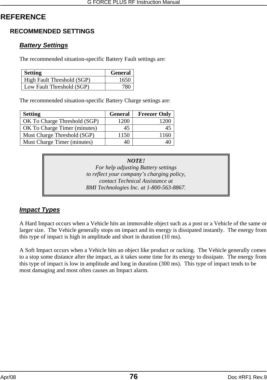
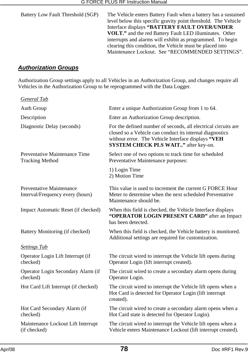
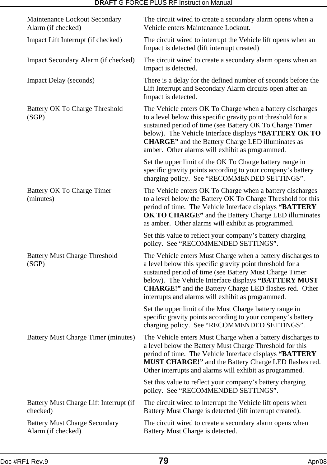
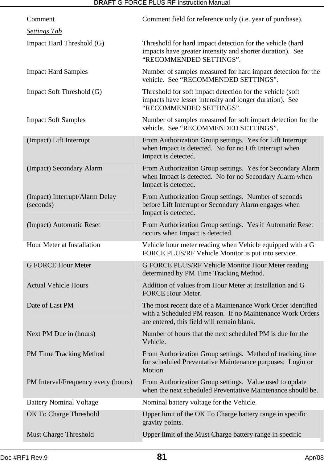
![G FORCE PLUS RF Instruction Manual Apr/08 80 Doc #RF1 Rev.9 Battery Must Charge Delay (minutes) There is a delay for the defined number of minutes before the Lift Interrupt and Secondary Alarm circuits open after Battery Must Charge is detected. Battery Fault Lift Interrupt (if checked) The circuit wired to interrupt the Vehicle lift opens when Battery Fault is detected (lift interrupt created). Battery Fault Secondary Alarm (if checked) The circuit wired to create a secondary alarm opens when Battery Fault is detected. Battery Fault Delay (minutes) There is a delay for the defined number of minutes before the Lift Interrupt and Secondary Alarm circuits open after Battery Fault is detected. Vehicle Defaults Tab RECOMMENDED BUT NOT MANDATORY Battery Nominal Voltage Set the default nominal battery voltage for Vehicles in this Authorization Group. Editable in Vehicle settings. Impact Hard Threshold (G) Set the default upper limit for Vehicles in the Authorization Group for determination of hard Impacts. Editable in Vehicle settings. Impact Hard Samples Set the default number of samples for Vehicles in the Authorization Group for determination of hard Impacts. Editable in Vehicle settings. Impact Soft Threshold (G) Set the default upper limit for Vehicles in the Authorization Group for determination of soft Impacts. Editable in Vehicle settings. Impact Soft Samples Set the default number of samples for Vehicles in the Authorization Group for determination of soft Impacts. Editable in Vehicle settings. Vehicles The Vehicle settings are specific to a Vehicle, and changes require the Vehicle to be reprogrammed with the Data Logger. Gray fields are read-only; they cannot be edited. General Tab Vehicle ID A system-assigned vehicle identifier for reference only. Vehicle No Enter the company-assigned vehicle identifier (i.e. Unit No). Serial No Enter the OEM serial number. Description Enter the Vehicle description (i.e. make, model, year purchased). Authorization Group Click the [Link To…] button to select the Authorization Group the Vehicle belongs to. Authorization Desc. Description of the Authorization Group the Vehicle belongs to. Rental (if checked) Indicates the Vehicle is a rental. For reference only.](https://usermanual.wiki/BMI-Technologies/RFVI/User-Guide-941196-Page-82.png)