BMI Technologies RFVI Vehicle User Interface RFID Reader User Manual
BMI Technologies Inc. Vehicle User Interface RFID Reader
user manual
BMI TECHNOLOGIES INC.
405, 1333 – 8th Street SW, Calgary, Alberta CANADA T2R 1M6
Toll-free: 1 800 563-8867 Tel: (403) 244-3901 Fax: (403) 229-0135
INSTRUCTION MANUAL
Document #RF1
Rev. 9

G FORCE PLUS RF Instruction Manual
TABLE OF CONTENTS
Doc #RF1 Rev.9 i Apr/08
INTRODUCTION ..........................................................................................................................4
SYSTEM DIAGRAM..............................................................................................................4
SYSTEM FEATURES ...........................................................................................................4
PARTS LIST..........................................................................................................................5
FCC AND IC REGULATORY DECLARATIONS...................................................................5
Special Accessories ......................................................................................................5
Interference ...................................................................................................................5
Component Changes or Modifications ..........................................................................6
RF Exposure Warning...................................................................................................6
DATA LOGGER TUTORIAL .................................................................................................6
VEHICLE AND SOFTWARE INTERFACE TECHNIQUES...................................................7
Vehicle Interface and Cards..........................................................................................7
Vehicle Interface and Data Logger................................................................................7
Software Interface and Cards........................................................................................8
Software Interface and Data Logger..............................................................................9
INSTRUCTION MANUAL CONVENTIONS ........................................................................10
QUICK-START................................................................................................................10
INSTALLATION INSTRUCTIONS..............................................................................................12
VEHICLE MONITOR AND INTERFACE.............................................................................12
Component Overview..................................................................................................12
Electrical Description...................................................................................................12
Installation Steps.........................................................................................................13
SOFTWARE AND INTERFACE..........................................................................................17
System Requirements.................................................................................................17
Software Interface Installation.....................................................................................18
Software Installation....................................................................................................18
RF TRANSCEIVERS ..........................................................................................................20
Component Overview..................................................................................................20
Installation Steps.........................................................................................................20
SYSTEM SETUP ........................................................................................................................22
SOFTWARE........................................................................................................................22
Starting the Software...................................................................................................22
Navigation ...................................................................................................................23
System Settings ..........................................................................................................24
Authorization Groups...................................................................................................26
Add an Authorization Group..............................................................................................27
Create a Vehicle Inspection Checklist ..............................................................................30
Edit the Custom Checklist.................................................................................................32
Edit an Authorization Group..............................................................................................33
Vehicles.......................................................................................................................34
Add a Vehicle....................................................................................................................34
Edit a Vehicle ....................................................................................................................36
Employees...................................................................................................................37
Add an Employee..............................................................................................................37
Define Vehicle Access Rules for an Operator ..................................................................38
Edit an Employee..............................................................................................................40
Transceivers................................................................................................................40
CARD ASSIGNMENT .........................................................................................................41
Set a Card Expiry Date................................................................................................41
Assign a Card..............................................................................................................43

G FORCE PLUS RF Instruction Manual
TABLE OF CONTENTS
Apr/08 ii Doc #RF1 Rev.9
VEHICLE MONITOR...........................................................................................................44
Initialize a Vehicle Monitor...........................................................................................44
Update Vehicle Monitor Settings.................................................................................48
VEHICLE OPERATION..............................................................................................................49
VEHICLE STARTUP ...........................................................................................................49
OPERATOR LOGIN............................................................................................................49
VEHICLE INSPECTION......................................................................................................50
OPERATING.......................................................................................................................50
IMPACT...............................................................................................................................51
HOT CARD .........................................................................................................................51
BATTERY MONITORING...........................................................................................................52
DO NOT CHARGE..............................................................................................................53
OK TO CHARGE.................................................................................................................53
MUST CHARGE..................................................................................................................53
BATTERY FAULT ...............................................................................................................54
Clear a Battery Fault ...................................................................................................54
VEHICLE MAINTENANCE.........................................................................................................55
MAINTENANCE LOCKOUT................................................................................................55
Why Lockout a Vehicle?..............................................................................................55
Lockout a Vehicle Manually.........................................................................................55
Override Maintenance Lockout Behavior ....................................................................56
Remove a Vehicle from Lockout .................................................................................56
MAINTENANCE WORK ORDERS......................................................................................56
Add a Work Order .......................................................................................................56
Edit a Work Order........................................................................................................57
PREVENTATIVE MAINTENANCE......................................................................................57
PM Due Notification.....................................................................................................57
Conduct Preventative Maintenance.............................................................................58
SYSTEM DATA ..........................................................................................................................59
EVENTS..............................................................................................................................59
Events Tab ..................................................................................................................60
Fleet Status Tab..........................................................................................................60
COLLECT DATA FROM A VEHICLE MANUALLY .............................................................60
DOWNLOAD DATA TO THE SOFTWARE MANUALLY.....................................................61
ADD A COMMENT ABOUT AN IMPACT............................................................................62
REPORTS...................................................................................................................................63
ORGANIZATION GROUPS ................................................................................................63
Add an Organization Group.........................................................................................64
Delete an Organization Group.....................................................................................64
Assign an Organization Group ....................................................................................65
Organization Group Examples ....................................................................................65
SAMPLE REPORTS ...........................................................................................................66
Vehicle Inspection Reports..........................................................................................66
Impact Reports............................................................................................................67
Login History Reports..................................................................................................67
Productivity Reports ....................................................................................................68
Maintenance Reports ..................................................................................................69
Fleet Summary Report ................................................................................................69

G FORCE PLUS RF Instruction Manual
TABLE OF CONTENTS
Doc #RF1 Rev.9 iii Apr/08
Card Status Report......................................................................................................70
EXPORTING REPORT DATA ............................................................................................70
ADDITIONAL SYSTEM FEATURES..........................................................................................71
PASSWORD .......................................................................................................................71
Set the Password ........................................................................................................71
Change the Password.................................................................................................71
Lost the Password?.....................................................................................................72
HOT CARDS .......................................................................................................................72
Maintain the Hot Card List...........................................................................................73
OTHER DATA LOGGER FUNCTIONS...............................................................................73
Clear Data (#9)............................................................................................................73
DATABASE MAINTENANCE ....................................................................................................74
SETTING UP BACKUP.......................................................................................................74
DELETING AGED RECORDS ............................................................................................75
REFERENCE..............................................................................................................................76
RECOMMENDED SETTINGS ............................................................................................76
Battery Settings...........................................................................................................76
Impact Types...............................................................................................................76
DATA FIELD DEFINITIONS................................................................................................77
System Settings ..........................................................................................................77
Authorization Groups...................................................................................................78
Vehicles.......................................................................................................................80
Employees...................................................................................................................82
TROUBLESHOOTING ........................................................................................................82
BACKING UP THE DATABASE..........................................................................................82
SOFTWARE LICENCE .......................................................................................................83
G FORCE PLUS RF Instruction Manual
Apr/08 4 Doc #RF1 Rev.9
INTRODUCTION
This section provides introductory information about the G FORCE PLUS RF Powered Industrial Vehicle Fleet
Management System. It also includes the necessary FCC and IC regulatory declarations.
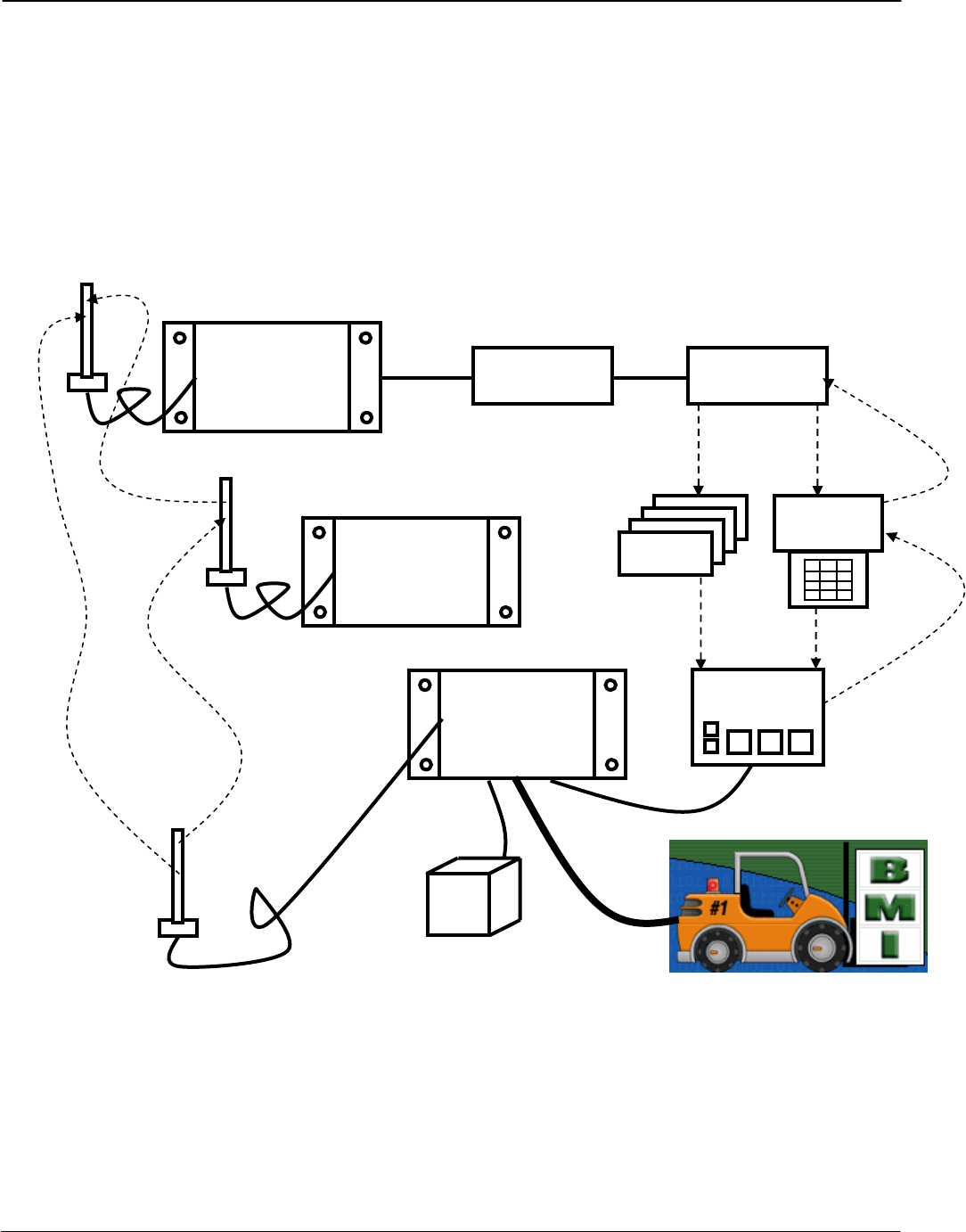
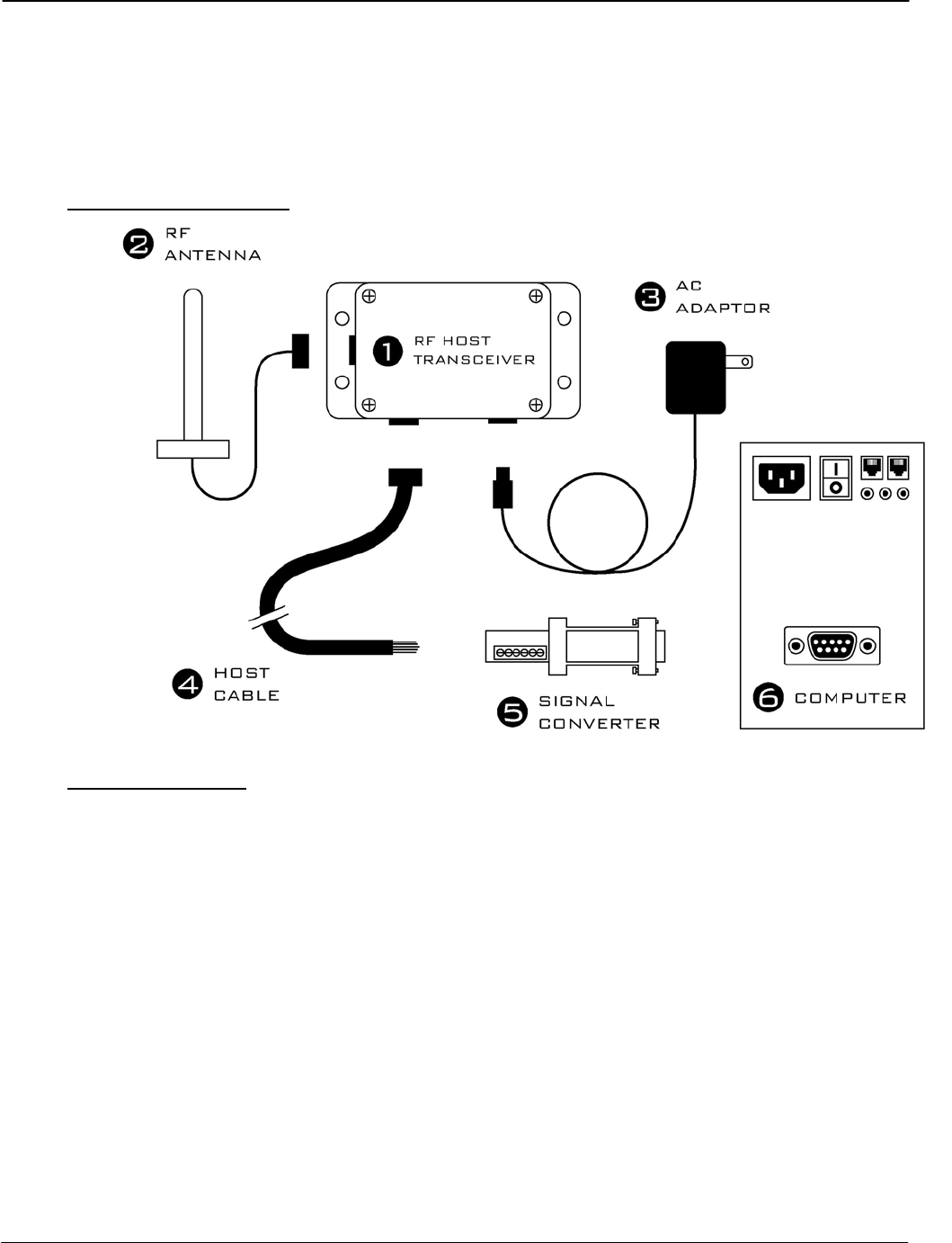
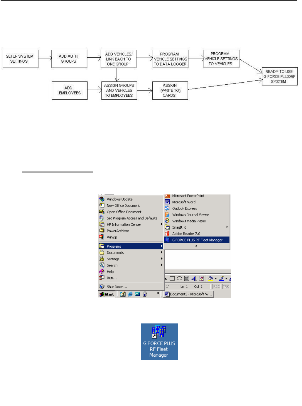
SYSTEM DIAGRAM
The following representation depicts the system components and their relationships. Solid lines indicate a
physical connection (i.e. cables, wires). Dotted lines indicate radio frequency communications.
SYSTEM FEATURES
The system includes the following features, which deliver cost savings, enhanced safety, and fleet
management and data collection via RF communications.
Vehicle access control and vehicle utilization
Electronic vehicle inspection checklist
PC with GF+
SOFTWARE SOFTWARE
INTERFACE
Optional:
RF HOST
TRANSCEIVER
Card validation Vehicle setup
Vehicle settings
programmed
DATA
LOGGER
CARDS
Card details
programmed
VEHICLE
INTERFACE
VEHICLE
MONITOR
Optional:
RF ZONE
TRANSCEIVER
(
1 or more
)
Optional:
RF
Data
collected
via R
F
Data
collected
manually

DRAFT G FORCE PLUS RF Instruction Manual
Doc #RF1 Rev.9 5 Apr/08
Impact monitoring
Battery monitoring for electric vehicles
Maintenance lockout, PM scheduling and work order entry
A user-friendly Vehicle Interface
Comprehensive reporting
Impact Reports sorted by Operator, Vehicle, Supervisor and Date/Times
Vehicle Login History (including logins and impacts) sorted by Operator ad Vehicle
Productivity Reports sorted by Operator and Vehicle
Standard status reports for Vehicles and Cards used in the system
Detailed and Summary Vehicle Maintenance Reports by Technician and Vehicle
Failed and Passed Vehicle Inspection Reports
Customizable settings, thresholds and alarms/interrupts/warnings
PARTS LIST
One (1) RF Vehicle Monitor per vehicle
One (1) Vehicle Interface per vehicle
One (1) copy of the Fleet Manager Software and Instruction Manual
One (1) Software Interface (reader/writer)
One (1) Data Logger
One (1) RF Host Transceiver
One (1) Host Cable
Cards for Operators, Supervisors and Maintenance Technicians (Lockout and Unlock)
One or more RF Zone Transceivers (optional)
FCC AND IC REGULATORY DECLARATIONS
Federal Communications Commission (FCC) and Industry Canada (IC) regulations require the inclusion of
this section in the Instruction Manual.
Special Accessories
The provided antenna, which operates in the 902 to 928 MHz frequency band, and antenna extension
cable, must be used with the G FORCE PLUS RF Host Transceiver, G FORCE PLUS RF Zone
Transceiver and G FORCE PLUS RF Vehicle Monitor. No substitutions are allowed.
Interference
The G FORCE PLUS RF Vehicle Monitor antenna and the G FORCE PLUS Vehicle Interface may not
be located closer than 20cm to each other.
These devices comply with Part 15 of the FCC Rules. Operation is subject to the following two
conditions: (1) the devices may not cause harmful interference, and (2) the devices must accept any
interference received, including interference that may cause undesired operation.

G FORCE PLUS RF Instruction Manual
Apr/08 6 Doc #RF1 Rev.9
Component Changes or Modifications
Changes or modifications not expressly approved by the party responsible for compliance could void the
user’s authority to operate the G FORCE PLUS Vehicle Interface, G FORCE PLUS Data Logger, G
FORCE PLUS RF Vehicle Monitor, G FORCE PLUS RF Host Transceiver, and G FORCE PLUS RF
Zone Transceiver.
RF Exposure Warning
The following warning applies to the G FORCE PLUS Vehicle Interface, G FORCE PLUS RF Vehicle
Monitor, G FORCE PLUS RF Host Transceiver, and G FORCE PLUS RF Zone Transceiver:
WARNING: This device meets the FCC/IC requirements for RF exposure when the antenna used for
this transmitter has a separation distance of at least 20 cm from all persons and must not be co-located or
operating in conjunction with any other antenna or transmitter which is closer than 20 cm.
The installer of this radio equipment must ensure that the antenna is located or pointed such that it does
not emit RF field in excess of Health Canada limits for the general population as indicated by Safety Code
6.
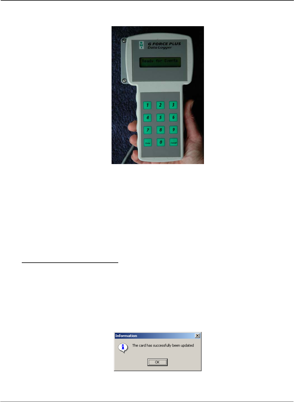
DATA LOGGER TUTORIAL
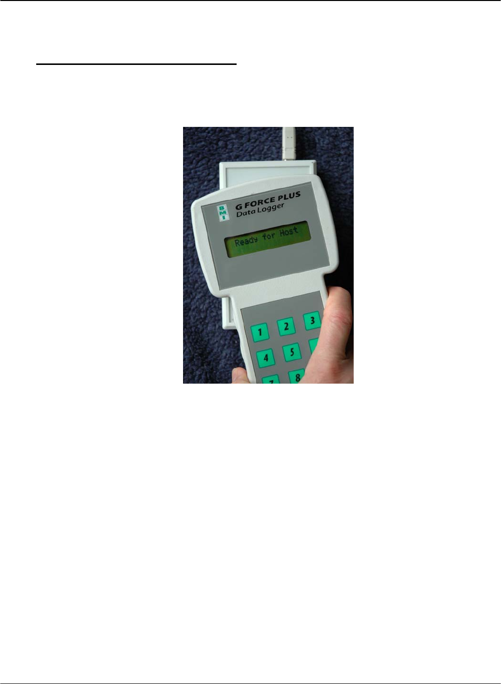
The Data Logger is a hand-held device used to transfer data between the Fleet Manager Software and a
Vehicle Monitor. The power source is a single 9-volt battery, stored in the battery compartment at the back of
the unit. A slot screwdriver opens the compartment for battery replacement.
1. Press {Enter} on the Data Logger to start its self-test. The Data Logger will display:
a. “Selftesting…”
b. “SelfTest Passed Firmware 1V6”
c. “Action?(1-9)”
2. Press each number one at a time from {1} to {9} and watch the Data Logger display change for each
selection:
Number Display Purpose
1 Events to PC Download Vehicle data to Software
2 Get Vehicle ID Get Vehicle ID from Software
3 Get Veh Settings Get Vehicle settings from Software
4 Events from Veh Collect Vehicle data (backup data collection method)
5 Prog Veh ID Program Vehicle ID to Vehicle Monitor
6 Prog Veh Settngs Program Vehicle settings to Vehicle Monitor
7 Date / Time Transfer Date / Time from Software to Data Logger to Vehicle
8 Hot Card List Transfer Hot Card List from Software to Data Logger to Vehicle
9 Clear Data Clear Data Logger data (ID’s, Settings, and Events)
3. Press {7}. The Data Logger will display “Action?(1-9) Date / Time”
4. Press {Cancel}. The Data Logger will revert to “Action?(1-9)”
5. Press {4}. The Data Logger will display “Action?(1-9) Events from Veh”
6. Press {Enter}. The DATA LOGGER will display “Ready for Events”
7. Do not press the keypad for one minute. The Data Logger will automatically shut down.
DRAFT G FORCE PLUS RF Instruction Manual
Doc #RF1 Rev.9 7 Apr/08
See “Initialize a Vehicle Monitor” for instructions on how functions 2, 3, 5, and 6 are used together to
program Vehicle settings from the Software to a Vehicle Monitor.
See “SYSTEM DATA” for instructions on how functions 1 and 4 are used together to manually transfer
data from a Vehicle to the Software in the event of a breakdown in RF communications.
See “OTHER DATA LOGGER FUNCTIONS” for instructions function 9.
VEHICLE AND SOFTWARE INTERFACE TECHNIQUES
Both the Vehicle Interface and the Software Interface require interaction with Cards and with the Data
Logger. The methods of interaction are illustrated below:
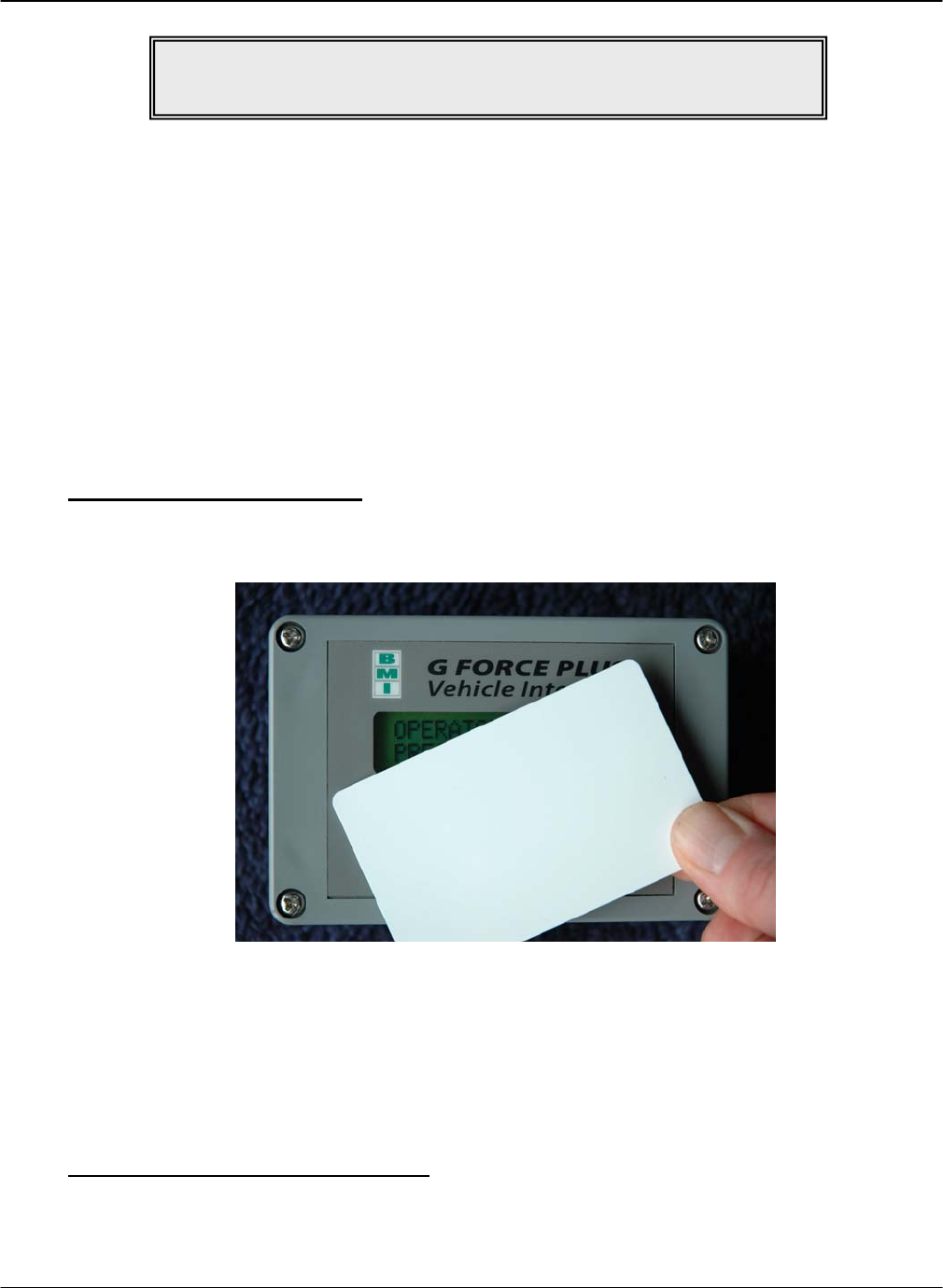
Vehicle Interface and Cards
1. Hold the Card parallel to the face of the Vehicle Interface, making sure they are within 1” of each
other.
2. Listen for the Vehicle Interface buzzer to sound, or to stop sounding as the case may be. This
indicates the Card has been recognized.
3. Remove the Card from the Vehicle Interface and read the display for further information.
4. If the Vehicle Interface fails to recognize the Card, remove it from the Vehicle Interface by
approximately 12” and retry.
Vehicle Interface and Data Logger
1. Place the Vehicle into Maintenance Lockout.
2. Prepare the Data Logger for the interaction by selecting the desired function.
NOTE!
Press {Cancel} to return the Data Logger to “Action?(1-9)” at any time.
G FORCE PLUS RF Instruction Manual
Apr/08 8 Doc #RF1 Rev.9
3. Hold the Data Logger parallel to the face of the Vehicle Interface, making sure they are within 1” of
each other.
4. Listen for a single beep from the Vehicle Interface. This indicates the Data Logger has been
recognized.
5. Refer to instructions for individual functions to learn when the Vehicle Interface / Data Logger
interaction is complete for that function.
6. When the interaction is complete, remove the Data Logger from the Vehicle Interface and read the
Vehicle Interface display for further information.
7. If the Vehicle Interface fails to recognize the Data Logger, remove it from the Vehicle Interface by
approximately 12” and retry.
Software Interface and Cards
1. Hold the Card parallel to the top of the Software Interface, making sure they are within 1” of each
other (or lay the Card on the Software Interface).
2. Initiate the interaction between the Software Interface and Card by selecting the desired task from the
Fleet Manager Software.
3. Watch the Software for progress of the interaction.
4. Click the [OK] button to confirm completion of the interaction when prompted by the Software.
5. Remove the Card from the Software Interface.
DRAFT G FORCE PLUS RF Instruction Manual
Doc #RF1 Rev.9 9 Apr/08
6. If the interaction fails, remove the Card from the Software Interface by approximately 12” and retry.
Software Interface and Data Logger
1. Prepare the Data Logger for the interaction by selecting the desired Data Logger function.
2. Hold the Data Logger parallel to the top of the Software Interface, making sure they are within 1” of
each other (or lay the Data Logger on the Software Interface).
3. Initiate the interaction between the Software Interface and Data Logger by selecting the desired task
from the Fleet Manager Software.
4. Watch the Software for progress of the interaction.
5. Click the [OK] button to confirm completion of the interaction when prompted by the Software.
6. Remove the Data Logger from the Software Interface.
7. If the interaction fails, remove the Data Logger from the Software Interface by approximately 12” and
retry.

G FORCE PLUS RF Instruction Manual
Apr/08 10 Doc #RF1 Rev.9
INSTRUCTION MANUAL CONVENTIONS
Software buttons [Add]
Software tabs Vehicles
Software menu items Setup | System Settings
Software windows “Add Vehicle”
Software fields Hours
Data Logger keys {Cancel}
Data Logger display “No Events!”
Vehicle Interface keys {Pass}
Vehicle Interface display “OPERATOR LOGIN PRESENT CARD”
QUICK-START
This Quick-Start section summarizes the system setup steps without providing detailed how-to instructions.
Complete them in the order shown. Detailed instructions follow beginning with the “INSTALLATION
INSTRUCTIONS”. Settings are described in the section “

DRAFT G FORCE PLUS RF Instruction Manual
Doc #RF1 Rev.9 11 Apr/08
DATA FIELD DEFINITIONS”.
1. Install the Vehicle Monitors and Interfaces.
2. Install the Fleet Manager Software and Interface.
3. Install the RF Transceivers.
4. Set up the Fleet Manager Software.
a. Define settings that apply to all Vehicles (Setup | System Settings menu).
b. Define (up to 64) Authorization Groups and group settings (Authorization Groups tab).
i. Add Authorization Groups and settings ([Add] button).
ii. Select Vehicle Inspection checklist (Inspection List lower tab).
iii. Select more Vehicle Inspection checklist items (Custom List lower tab).
iv. Add more user-defined checklist items if required (Setup | Custom Check List menu).
c. Define Vehicles and Vehicle settings and link each Vehicle to one Authorization Group (Vehicles tab,
[Add] button).
d. Define Employees and vehicle access rules for Employees (Employees tab).
i. Add Employees and Employee details ([Add] button).
ii. Assign (up to 64) Authorization Groups to each Operator (Assign Authorization Groups lower
tab).
iii. Assign (up to 32) Single Vehicles to each Operator (Assign Single Vehicles lower tab).
e. Customize RF Transceiver descriptions (Setup | Zone Description menu).
5. Assign Cards to Employees.
6. Initialize the Vehicle Monitors with the Data Logger.
7. Begin system operation.
G FORCE PLUS RF Instruction Manual
Apr/08 12 Doc #RF1 Rev.9
INSTALLATION INSTRUCTIONS
This section provides the installation instructions for the G FORCE PLUS RF system.
VEHICLE MONITOR AND INTERFACE
The Vehicle Monitor and Vehicle Interface installation instructions follow. A copy is also included with each
Vehicle Monitor shipped.
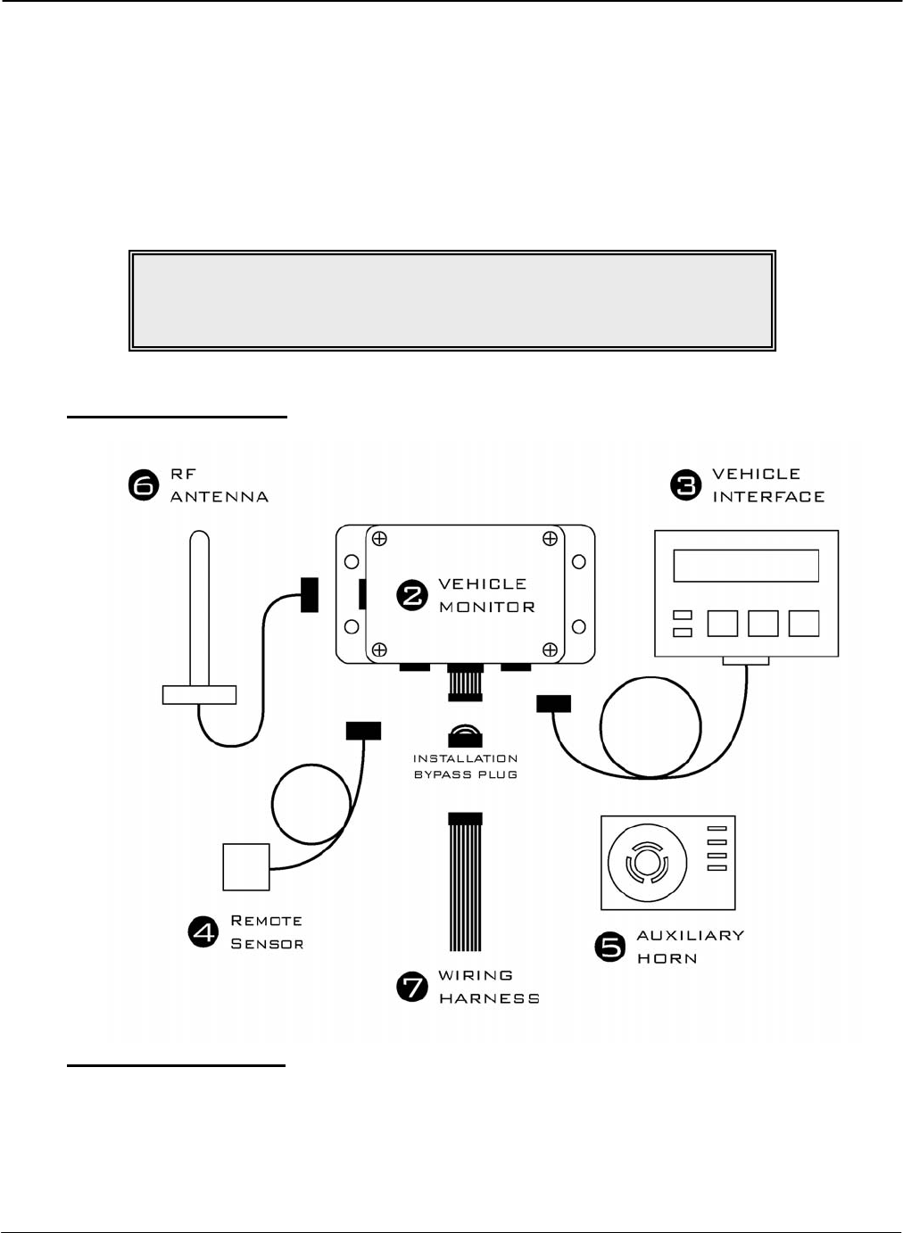
Component Overview
Electrical Description
Input Fuse (F1) 12 – 60 volts 1A DC Slow
Lift Interrupt Relay Fuse (F2) Max 60 volts 3.5A DC Slow
Secondary Alarm Relay Fuse (F4) Max 60 volts 3A DC Slow
Horn Relay Fuse (F3) Max 60 volts 3A DC Slow
NOTE!
Vehicle Monitor and Vehicle Interface installation may be done
at the same time as the Software and Software Interface installation.

DRAFT G FORCE PLUS RF Instruction Manual
Doc #RF1 Rev.9 13 Apr/08
Installation Steps
Follow the steps in the order below and refer to the diagram in the “Component Overview”.
1. Disconnect the vehicle battery
Check the power circuit with a multi-meter or other testing device to ensure the absence of any
residual voltage.
2. Mount the Vehicle Monitor onto the vehicle.
The optimal location for the Vehicle Monitor is within the plan form of the vehicle where it will
be safe from electrical controls, engine heat, possible impacts, and vandalism.
Use the base of the Vehicle Monitor as a template to drill four ¼-inch holes in the selected
location and attach the Vehicle Monitor using the hardware provided.
3. Mount and connect the Vehicle Interface.
The Vehicle Monitor antenna and the Vehicle Interface may not be located closer than 20cm to
each other.
Secure the Vehicle Interface to an ergonomically accessible location on the Vehicle.
Feed the Vehicle Interface cable to the Vehicle Monitor and plug the cable end’s 4-pin male
connector into the 4-pin female receptacle on the Vehicle Monitor. Secure the connector.
NOTE!
Wires and cables should be installed to avoid chafing and excess slack.
Cable ties, clamps, grommets, looms, sleeves, supplementary insulation,
conduit, and routing are acceptable provisions.
Wires and cables mounted on a boom, lift, or other similar moving part
should be installed so that they are not subject to damage or failure as a
result of kinking or abrasion.
Wires and cables should be installed to maintain clearance from moving
parts, hot engine parts, exhaust systems, fuel systems and surfaces that are
subject to accumulation of oil, grease, or dirt.
NOTE!
The G FORCE PLUS RF Vehicle Monitor antenna and
the G FORCE PLUS Vehicle Interface
may not be located closer than 20cm to each other.
WARNING!
This device meets the FCC/IC requirements for RF exposure when the
antenna used for this transmitter has a separation distance of at least 20 cm
from all persons and must not be co-located or operating in conjunction with
any other antenna or transmitter which is closer than 20 cm.
The installer of this radio equipment must ensure that the antenna is located
or pointed such that it does not emit RF field in excess of Health Canada
limits for the general population as indicated by Safety Code 6.

G FORCE PLUS RF Instruction Manual
Apr/08 14 Doc #RF1 Rev.9
4. Mount and connect the Remote Sensor.
The optimal location for the Remote Sensor is on a rigid part of the vehicle 2 to 4 feet from the
floor (i.e. the frame). Overhead racks or masts are unsuitable.
Some recommended mounting locations are:
Sit-downs: Under the floor plate on the left or right side frame with a minimum
distance of 12 inches from the battery compartment on battery-powered
vehicles
Stand-ups: 1-2 inches below the front cover/dash on the left or right inside perimeter
of the frame
Turret trucks: As high as possible on the main frame and as close as possible to the mast.
Walkies: As low as possible under the cowl/cover on the main frame.
Walkie-riders: As low as possible under the cowl/cover on the main frame.
Use the metal bracket provided to mount the Remote Sensor as parallel to the floor as possible,
and so that the labelled arrows match the direction of the vehicle’s travel (the cable should exit
from the top or bottom of the Remote Sensor).
Or if preferred, clean the mounting surface thoroughly with degreaser and then mount the Remote
Sensor using the 3M™ Dual Lock™ provided.
Feed the Remote Sensor cable to the Vehicle Monitor and plug the cable end’s 6-pin male
connector into the 6-pin female receptacle on the Vehicle Monitor. Secure the connector.
Secure the cable to the vehicle within 3 inches of the Remote Sensor.
5. Mount the Auxiliary Horn.
The optimal location for the Auxiliary Horn is where it will be audible and safe from electrical
controls, engine heat and vandalism.
Clean the mounting surface thoroughly with degreaser and then mount the Horn using the 3M™
Dual Lock™ provided.
6. Mount and connect the antenna.
The optimal location for the antenna is:
On a rigid part of the vehicle, safe from electrical controls, engine heat, moving parts and
vandalism,
As high as possible from the floor,
At least two feet away from any large metal mass for best communications results.
Attach the metal bracket provided to the selected location so the antenna will be vertical.
Insert the antenna into the bracket slot and secure the antenna by tightening the nut.
Prevent movement/vibration of the metal connector located between the short black and long
copper-colored cables by securing the cables and protecting the connector if necessary.
7. Wire the Vehicle Monitor.
Remove the Installation Bypass Plug from the end of the Wiring Harness and connect the Wiring
Harness to the Vehicle Monitor.
NOTE!
The provided antenna, which operates in the 902 to 928 MHz frequency
band, and antenna extension cable,
must be used with the G FORCE PLUS RF Vehicle Monitor.
No substitutions are allowed.

DRAFT G FORCE PLUS RF Instruction Manual
Doc #RF1 Rev.9 15 Apr/08
Connect the wires to the vehicle as follows:
Orange wire/battery positive: Connect this wire to unswitched battery positive on a 12-
volt IC truck. Tie this wire back if it is not used.
Red wire/battery positive: Connect this wire to unswitched battery positive on a 12-
or 24-volt battery. Tie this wire back if it is not used.
Red and white wire/battery positive: Connect this wire to unswitched battery positive on a 36-
or 48-volt battery. Tie this wire back if it is not used, or
if this is an internal-combustion vehicle installation.
Black wire/battery negative: For battery-powered vehicles, connect this wire directly
to battery negative as close to the battery terminal as
possible. For internal-combustion vehicles, connect this
wire to the frame or any vehicle ground.
Green wires/key-on detect: Connect one green wire to switched battery plus.
IMPORTANT! On an IC truck, this green wire MUST
be connected to the IGNITION contact of the keyswitch,
not the ACCESSORY contact. If it is connected to the
accessory contact, the connection will be broken when
the starter is engaged, which will turn the GForce unit
off.
Connect the second green wire directly to battery minus
as close to the battery terminal as possible. For internal-
combustion vehicles, connect the second green wire to
the frame or any vehicle ground.
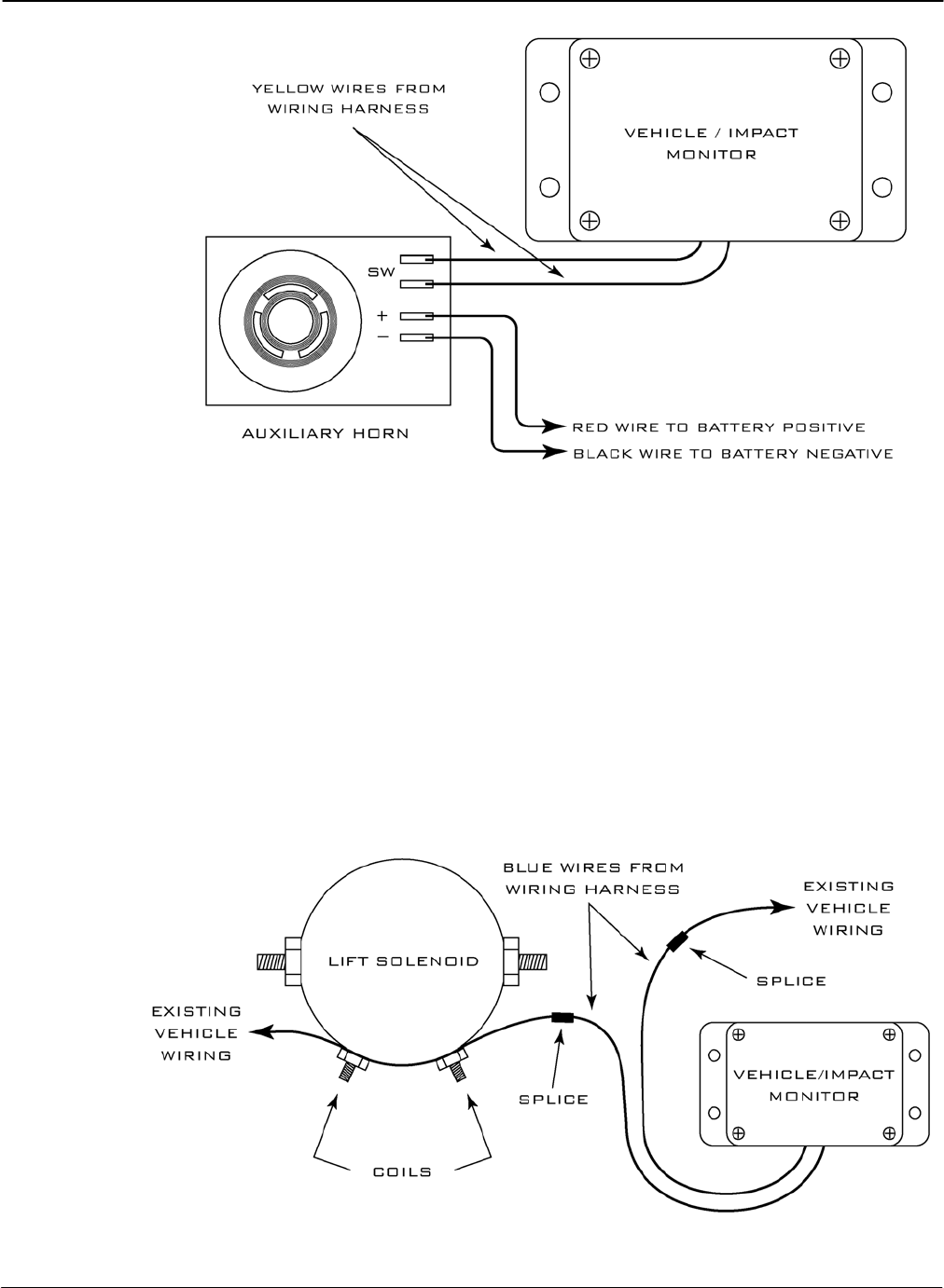
Yellow wires/Auxiliary Horn: Connect one yellow wire to one of the two Auxiliary
Horn terminals labelled “SW”. Connect the second
yellow wire to the second Auxiliary Horn “SW”
terminal. Use a suitable length of red wire to make a
connection between the positive terminal on the
Auxiliary Horn (labelled “+”) and battery positive. An
unused portion of red battery positive wire from the
Wiring Harness may be used. Similarly, use a suitable
length of black wire to make a connection between the
negative terminal on the Auxiliary Horn (labelled “–”)
and battery negative. An unused portion of black battery
negative wire from the Wiring Harness may be used.
NOTE!
Keep the Installation Bypass Plug in a safe place.
You will need it again for step 9.
G FORCE PLUS RF Instruction Manual
Apr/08 16 Doc #RF1 Rev.9
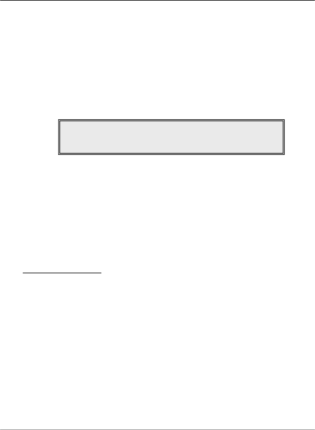
Blue wires/interrupt: Use these wires to interrupt a device on the vehicle if
desired. The contact on the blue wires is fused at 3 amps
– do not create a circuit that exceeds this rating. For
example, to interrupt a lift solenoid on an electric truck,
do the following. Remove one vehicle wire at the coil of
the lift solenoid. Splice one blue wire to the wire just
removed. Connect the other blue wire to the vehicle lift
solenoid terminal. Tie these wires back if they are not
used, or if this is an internal-combustion vehicle
installation. Other applications are possible if there is no
lift solenoid available. The wires are to be attached in
series with the device you want to disable, so that if the
connection is broken, the device will not have power and
disable the truck.
DRAFT G FORCE PLUS RF Instruction Manual
Doc #RF1 Rev.9 17 Apr/08
Purple wires/secondary alarm: Use these wires to interrupt a second device if desired.
The contact on the purple wires is fused at 3 amps – do
not create a circuit that exceeds this rating. For
customized help with your particular installation, contact
Technical Assistance at BMI Technologies Inc. at 1-800-
563-8867. Tie these wires back if they are not used.
8. Reconnect the battery and turn on the vehicle ignition to test the installation.
The vehicle should power up and the Vehicle will be in Maintenance Lockout. The Vehicle
Interface will display “MAINT LOCK OUT DD/MM/YYYY HH:MM”.
If the blue wires were connected for lift interrupt, the lift will be disabled.
If the purple wires were connected for a secondary alarm, the vehicle’s behavior will reflect a
secondary alarm condition.
9. Complete or pause the installation.
Refer to the section “Initialize a Vehicle Monitor” to program the Vehicle Monitor settings, OR
Disconnect the Vehicle Monitor and Wiring Harness and reconnect the Installation Bypass Plug
to the end of the Wiring Harness to allow full vehicle use and to defer the programming of
Vehicle Monitor settings.
SOFTWARE AND INTERFACE
PC Software and Interface installation may be done at the same time as the Vehicle Monitor and Interface
installation. The Software Interface must be installed before the Software is installed.
System Requirements
Stand-alone IBM PC or compatible
Microsoft® Windows XP Pro
CD-ROM drive
USB port
9-pin serial port
NOTE!
If the installation test fails, contact Technical Assistance
at BMI Technologies Inc. at 1-800-563-8867.
G FORCE PLUS RF Instruction Manual
Apr/08 18 Doc #RF1 Rev.9
Software Interface Installation
The Software Interface is used to read from and write to Cards and the Data Logger. To install it:
1. Connect the Software Interface to your computer using the USB cable supplied.
2. Insert the CD that came with the Software Interface.
3. The installation is complete when Software Interface LED indicates green.
Software Installation
The following instructions are for a standalone installation of the Software.
1. Close all open files and applications on your computer, including any anti-virus software.
2. Insert the installation CD into your computer’s CD-ROM drive.
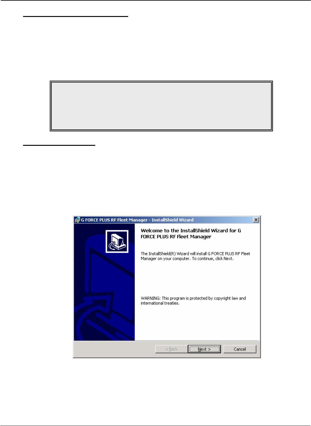
3. Double-click the “Setup.exe” file on the CD to begin the installation process and follow the
InstallShield® Wizard onscreen installation steps, accepting the default program location provided.
.
4. Remove the installation CD when Setup is complete.
NOTE!
If the Software Interface LED indicates flashing amber, your PC has not
automatically detected the Interface. If this is the case, follow the steps
outlined in the third-party FEIG Electronic OBID® USB-Driver installation
instructions for your particular operating system.
DRAFT G FORCE PLUS RF Instruction Manual
Doc #RF1 Rev.9 19 Apr/08
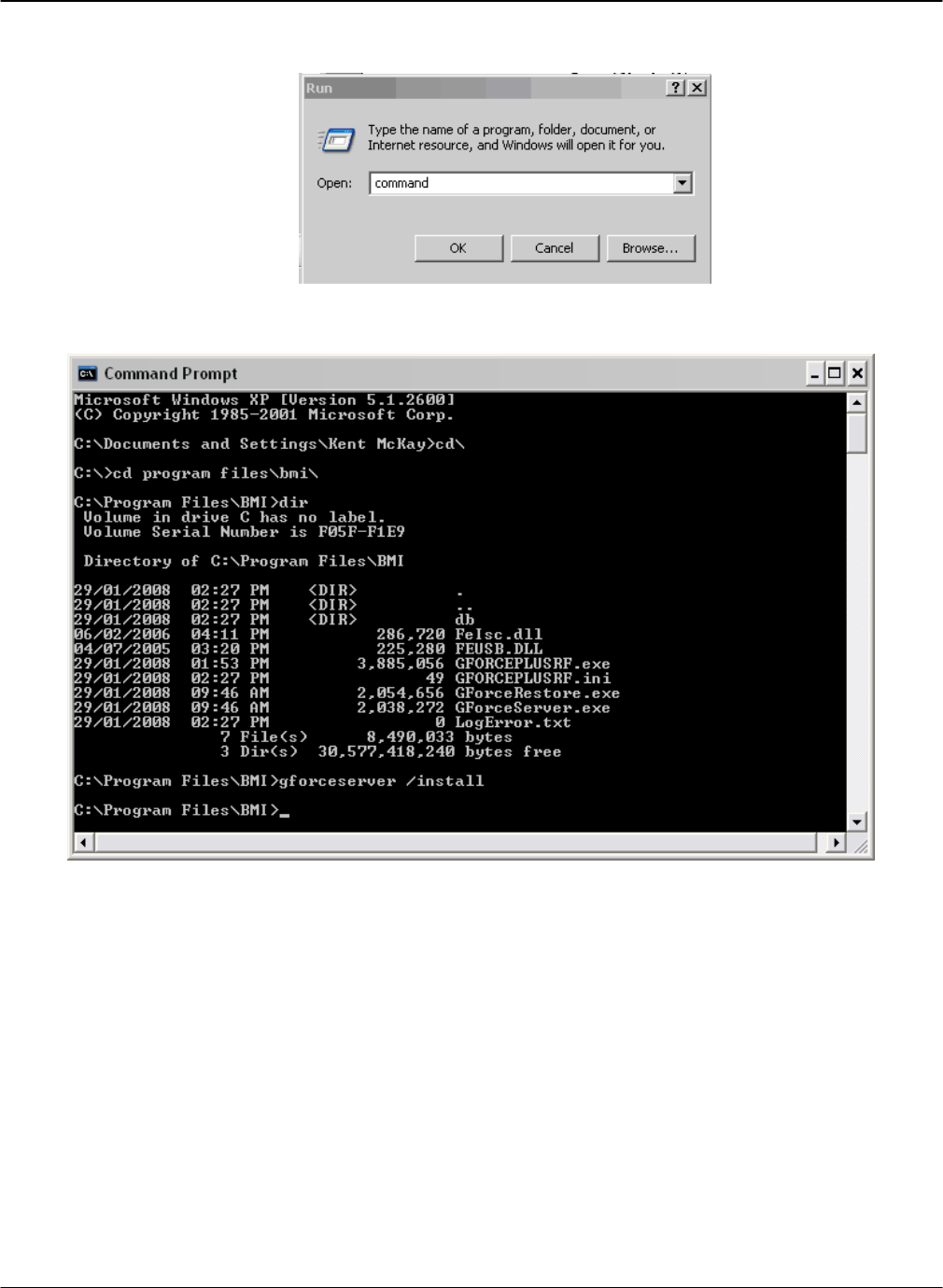
5. Click Start->Run.
6. Enter “command” into the Open: box.
7. Type “cd c:\progra~1\bmi”.
8. Type “gforceserver /install”. You should get a success message.
9. Click Ok.
10. Close the command window.
11. Reboot your computer.
G FORCE PLUS RF Instruction Manual
Apr/08 20 Doc #RF1 Rev.9
RF TRANSCEIVERS
The RF Transceivers are used to create a wireless communications link between the Vehicle Monitors and the
Software. The Host Transceiver has a physical connection to the computer. The Zone Transceivers are added
to extend the communications coverage area by placing each of them within range of the Host Transceiver.
Component Overview
Installation Steps
Follow the steps in the order below and refer to diagram in “Component Overview”.
1. Mount the Transceiver in the selected location.
The optimal location for a Transceiver and antenna is:
Where it will be safe from environmental hazards, possible impacts, and vandalism,
As high as possible from the floor,
At least two feet away from any large metal mass for best communications results,
Use the base of the Transceiver as a template to drill four ¼-inch holes in the selected location
and attach the Transceiver using the hardware provided.
2. Mount and connect the antenna.
Attach the metal bracket provided to the selected location so the antenna will be vertical.
Insert the antenna into the bracket slot and secure the antenna by tightening the nut.
Prevent movement/vibration of the metal connector located between the short black and long
copper-colored antenna cables by securing them and protecting the connector if necessary.
DRAFT G FORCE PLUS RF Instruction Manual
Doc #RF1 Rev.9 21 Apr/08
3. Supply the Transceiver with 110v power.
Plug the power supply of the AC adaptor into a standard 110v outlet.
Connect the other end of the adaptor to the Transceiver.
4. Install and connect the Host Cable (Host Transceiver only).
Feed the Host Cable between the Host Transceiver and the computer running the Software.
Plug the Host Cable’s 6-pin male connector into the 6-pin female receptacle on the Host
Transceiver.
Secure the connector.
Secure the Host Cable within 12” of the connector to prevent accidental disconnection.
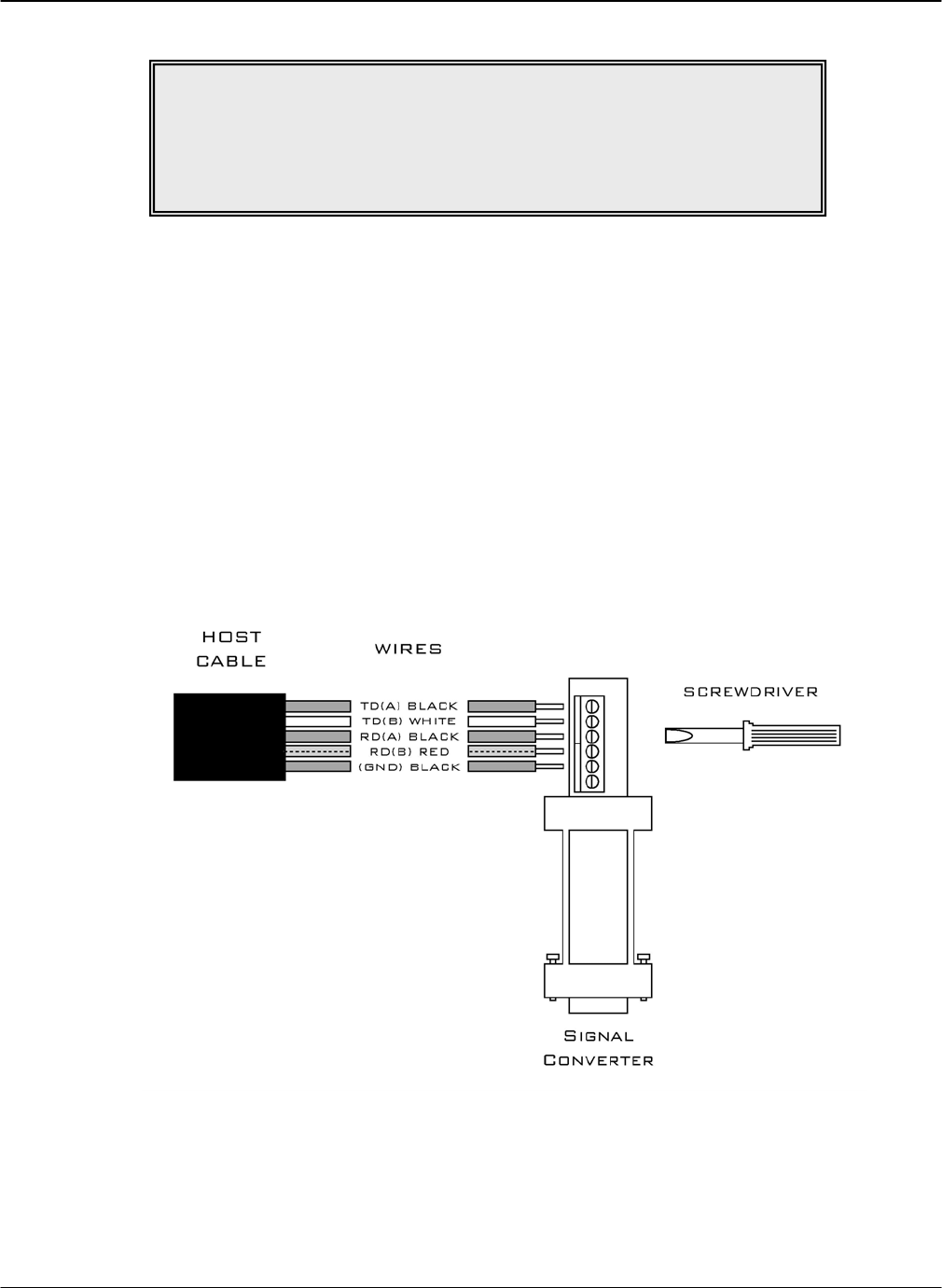
5. Connect the Host Cable and the Signal Converter (Host Transceiver only).
Connect the individual wires in the Host Cable to the Signal Converter as shown in the diagram
below, matching the labeling on the wires and the Converter
6. Connect the Host Transceiver and the computer.
Insert the Signal Converter’s 9-pin female receptacle into the computer’s 9-pin serial port.
NOTE!
The provided antenna, which operates in the 902 to 928 MHz frequency
band, and antenna extension cable, must be used with the
G FORCE PLUS RF Host and Zone Transceivers.
No substitutions are allowed.
G FORCE PLUS RF Instruction Manual
Apr/08 22 Doc #RF1 Rev.9
SYSTEM SETUP
This section provides the setup instructions for the G FORCE PLUS RF system. The diagram summarizes the
setup order.
SOFTWARE
This section provides an overview of the Software, and outlines how to setup the Software for use with the G
FORCE PLUS RF system.
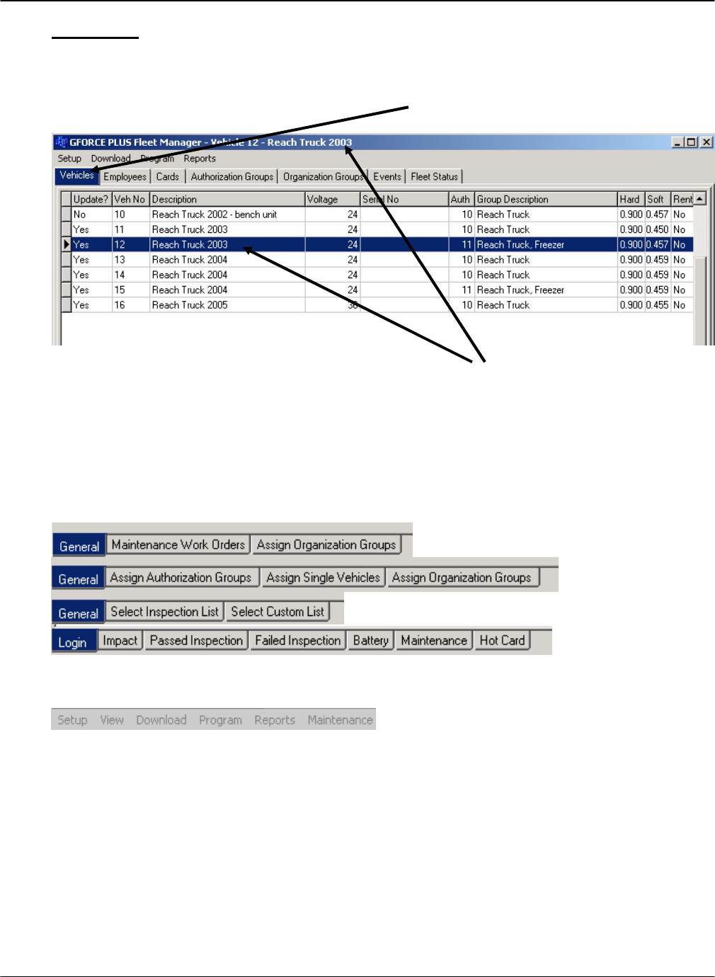
Starting the Software
1. Start the Software by selecting “G FORCE PLUS RF Fleet Manager” from the “Programs” menu
2. Or, double-click the Desktop shortcut created during the Software installation steps.
DRAFT G FORCE PLUS RF Instruction Manual
Doc #RF1 Rev.9 23 Apr/08
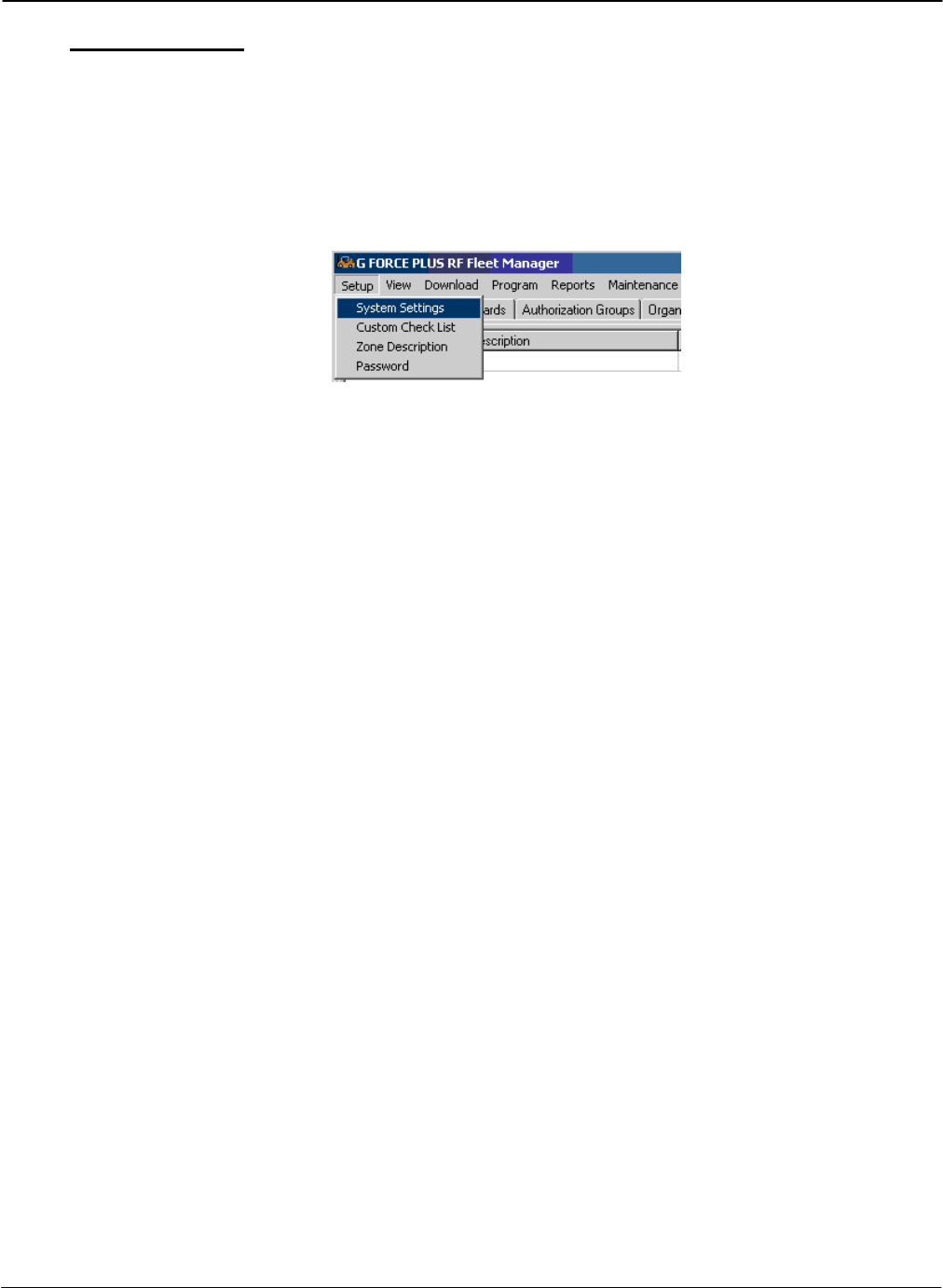
Navigation
The system’s data is displayed in a file folder format, organized by tabs.
Navigate the Software by clicking on the desired tab; the selected tab will display as highlighted.
Similarly, when a line item is selected, the selected line item will display as highlighted and the title bar
will display the description of the selected item.
For most tabs, double-clicking a line item will open a window that allows editing of the selected item.
For the Vehicles, Employees, Authorization Groups, and Events tabs, note the additional tabs at the
bottom of the Software. These are used to store additional information related to the selected line item or
tab.
The menu provides access to additional system setup information, data collection, reports, and software
maintenance.
G FORCE PLUS RF Instruction Manual
Apr/08 24 Doc #RF1 Rev.9
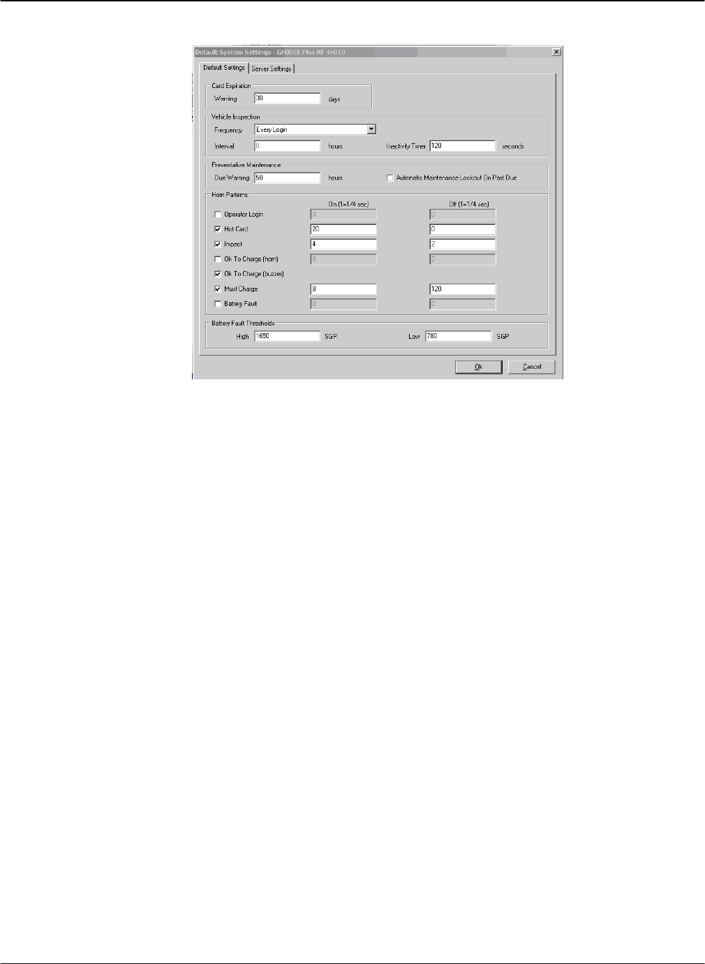
System Settings
This section begins the detailed how-to instructions for Software setup. Begin with the System Settings
and follow the Instruction Manual along in the order shown.
Settings defined in the “System Settings” window apply to all Vehicles in a fleet. If a change is made to
the System Settings, all Vehicles in the fleet must be reprogrammed using the Data Logger.
1. Select Setup | System Settings…from the menu.
2. Complete the System Settings fields according to the requirements for your operation. Settings are
defined in the section “
DRAFT G FORCE PLUS RF Instruction Manual
Doc #RF1 Rev.9 25 Apr/08
DATA FIELD DEFINITIONS”.
Items of Note:
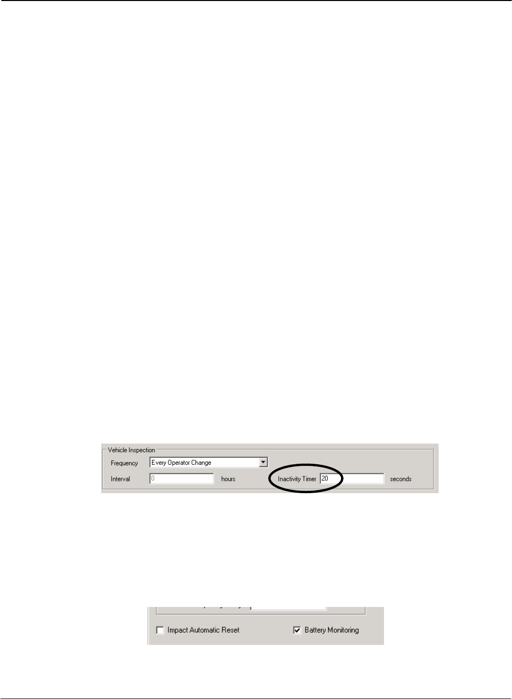
Vehicle Inspection Interval: How many hours after the last inspection before another
will be required if the inspection frequency requires it.
Vehicle Inspection Frequency: How often the GForce Plus will require the safety
checklist to be performed. Options:
Every Login: Requires a safety inspection every time a driver logs into the truck.
Does not use the interval.
Every Operator Change: Requires a safety inspection every time a new
operator logs onto the truck. Does not use the interval.
First Login per Operator per Interval: If an inspection hasn’t been performed
by the operator currently logging in within the time specified in Interval, the
operator must do a safety check.
First Login per Interval: If an inspection hasn’t been performed by anybody
within the time specified in Interval, the operator must do a safety check.
G FORCE PLUS RF Instruction Manual
Apr/08 26 Doc #RF1 Rev.9
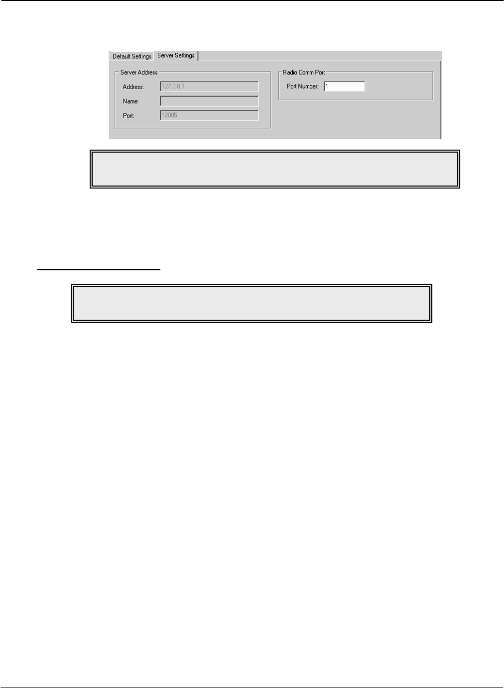
3. Radio Comm Port under the Server Settings tab is where you set which Serial port on the computer
the Host Transceiver is connected to.
4. Click the [OK] button to save the changes. Reboot if required.
Authorization Groups
Primarily, Authorization Groups are how vehicle access rules are defined. Each Vehicle is assigned to a
single Authorization Group and each Operator is assigned up to 64 Authorization Groups. The Operator
then has access to all Vehicles in the assigned Authorization Groups.
Consider creating a unique Authorization Group where vehicles require different:
Vehicle Inspection checklists
Operating and training requirements (i.e. electric vs. internal combustion, pallet jacks vs. order
pickers)
Preventative Maintenance scheduling (i.e. leased vs. owned)
Interrupts and alarms (re: battery monitoring for electrics vs. none for internal combustion)
Battery settings due to operating environment (i.e. freezer vehicles)
NOTE!
Authorization Groups must be set up before
NOTE!
A
reboot is re
q
uired when the Port Number is chan
g
ed.

DRAFT G FORCE PLUS RF Instruction Manual
Doc #RF1 Rev.9 27 Apr/08
Add an Authorization Group
1. Select the Authorization Groups | General tab.
2. Click the [Add] button to open the “Add Authorization Group” window. Settings are explained
in the section “
G FORCE PLUS RF Instruction Manual
Apr/08 28 Doc #RF1 Rev.9
DATA FIELD DEFINITIONS”.
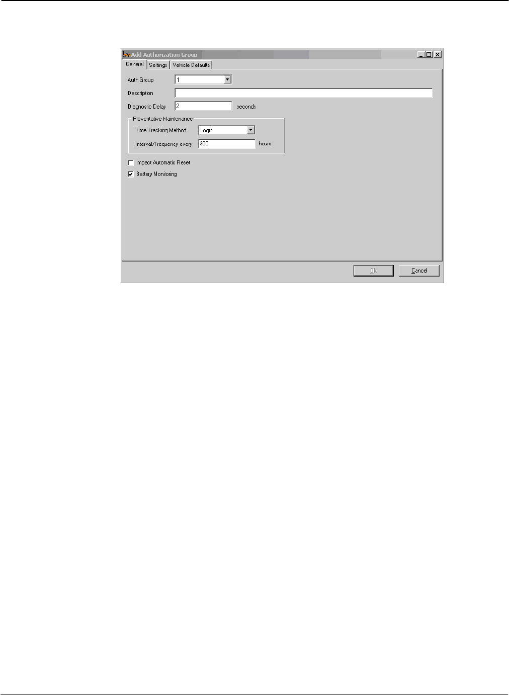
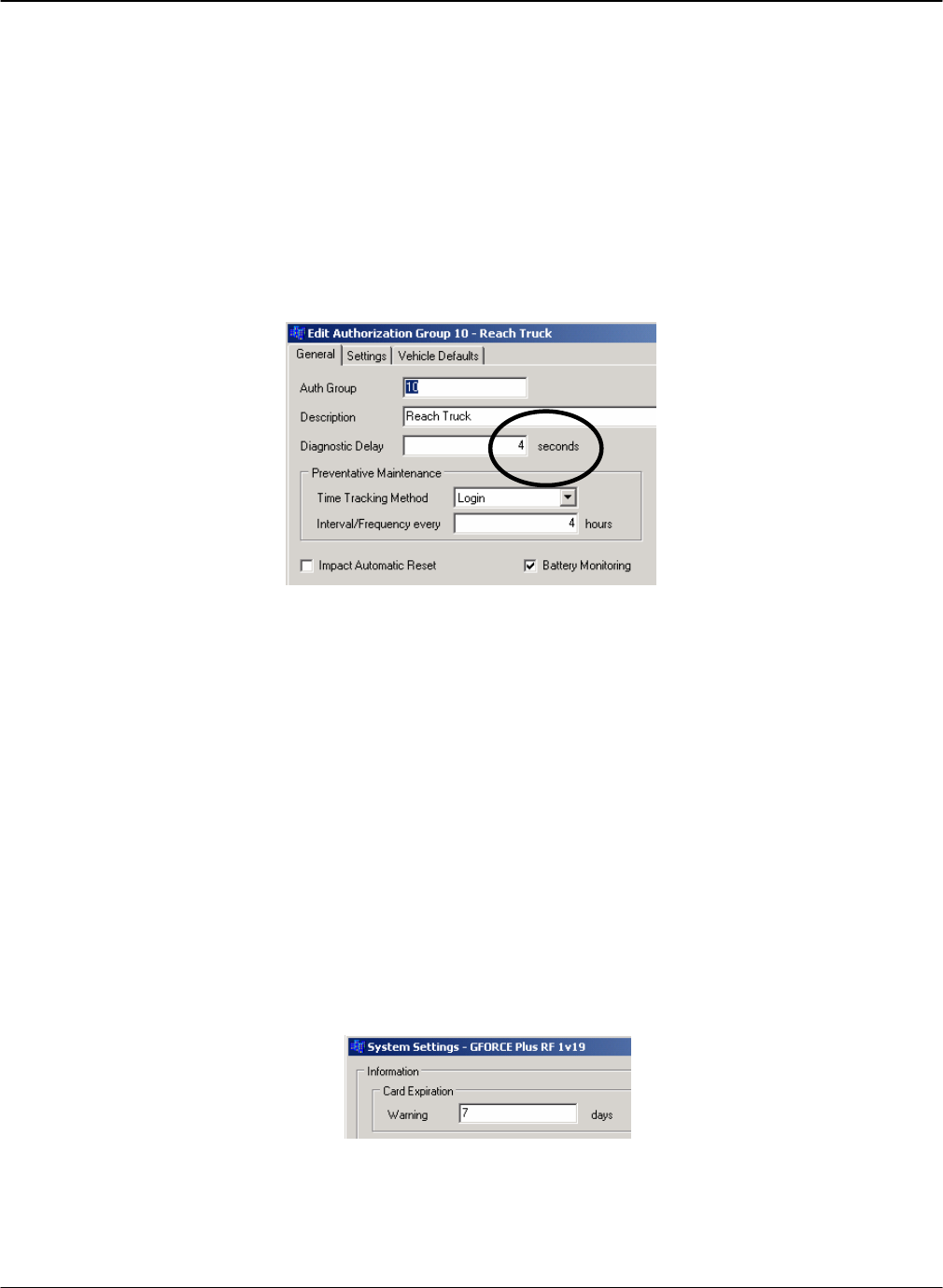
a. Complete the fields on the General tab.
Auth Group: An identifying number for the authorization group. You may have up to
64 auth groups.
Diagnostic Delay: Some trucks have monitoring in them that can generate error codes if
the interrupt in the GForce is open when the truck starts. The Diagnostic Delay is how
long the GForce unit will keep the interrupt closed after startup before opening the
interrupt and disabling the truck to require a logon.
Time Tracking Method: Options are Login or Motion. Login means as long as a user is
logged in, the GForce preventative maintenance hour meter will run. Motion means as
long as the truck is moving, the GForce preventative maintenance hour meter will run.
Impact Automatic Reset: If this is checked, on impact the GForce will go into alarm for
5 seconds, then reset itself and send the impact data to the computer. If this is unchecked,
on impact the GForce will go into alarm until a supervisor card is applied to the interface.
Battery Monitoring: Enables/disables the battery monitoring capabilities of the GForce.
DRAFT G FORCE PLUS RF Instruction Manual
Doc #RF1 Rev.9 29 Apr/08
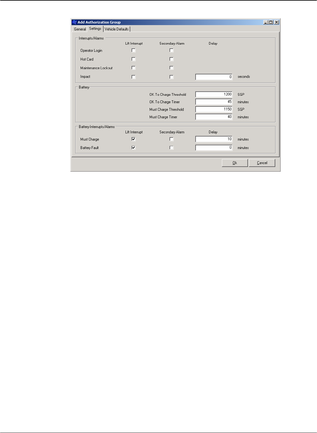
b. Complete the fields on the Settings tab.
Interrupts/Alarms: Checking or unchecking these boxes will enable or disable the Lift
Interrupt (blue wires) or Secondary Alarm (purple wires) connections on the listed
events.
Battery: These are the thresholds for battery conditions measured in specific gravity
points (SGP) which will cause the GForce to report OK to Charge or Must Charge
conditions for the battery if Battery Monitoring is enabled. The Timer fields are the
number of minutes of reading below the specified SGP before the GForce reports the
battery condition.
Battery Interrupts/Alarms: If checked, it will disable the truck if the must charge or
battery fault conditions are met for the listed number of minutes.
G FORCE PLUS RF Instruction Manual
Apr/08 30 Doc #RF1 Rev.9
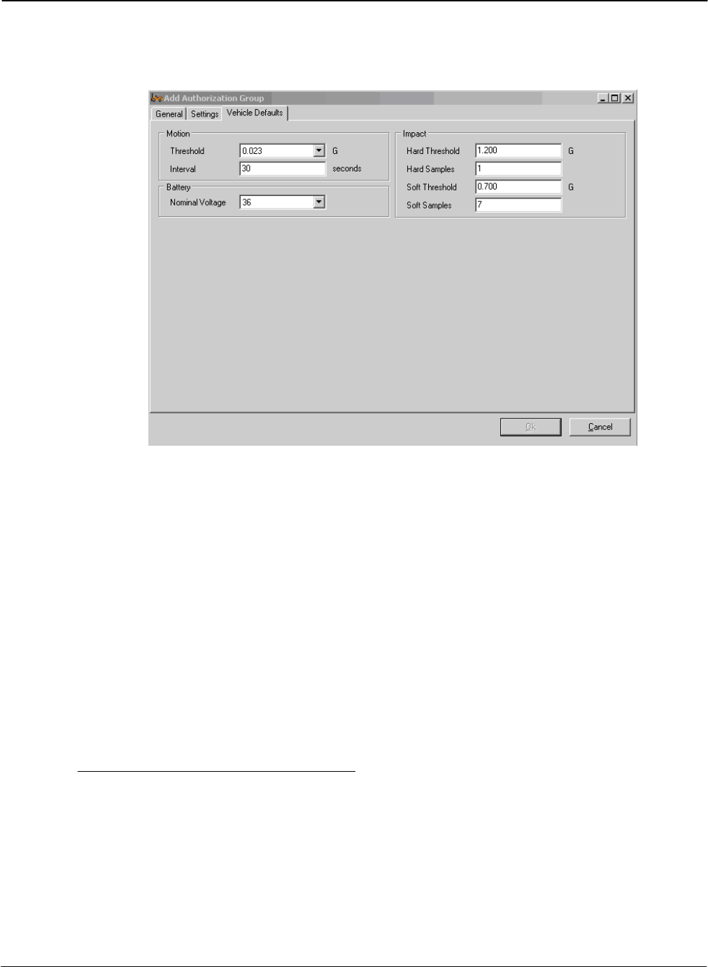
c. Complete the fields on the Vehicle Defaults tab. These values will become default values for
Vehicles assigned to this Authorization Group. They can be changed for individual trucks if
required in the Vehicle Settings tab.
Motion Threshold: The sensitivity of the GForce unit to determine if the truck is in
motion or not. A lower number means less acceleration is required to get the GForce to
sense motion.
Motion Interval: The amount of time since the last start, stop, or direction change that
the GForce will consider the truck in motion.
Battery Nominal Voltage: If battery monitoring is enabled, the voltage that is expected
of the battery.
Hard/Soft Threshold: The amount of force, expressed in Gs, it takes for the GForce to
register a Hard/Soft impact.
Hard/Soft Samples: The amount of time (in milliseconds) the hard/soft thresholds need
to be exceeded before the truck goes into Impact Alarm. Do not alter these in most
circumstances.
3. Click the [OK] button to save the changes.
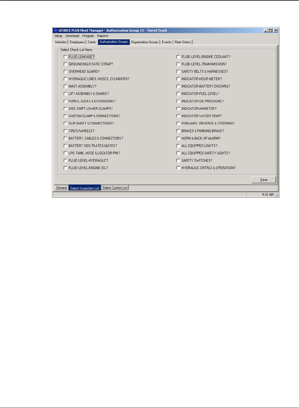
Create a Vehicle Inspection Checklist
The Vehicle Inspection Checklist for an Authorization Group is created by selecting from a list of 32
system-defined items, as well as adding up to 8 user-defined (custom) items. Each selected item is
displayed on the 2x16-character Vehicle Interface and requires a {Pass} or {Fail} response.
1. Select an Authorization Group from the grid.
2. Click on the Select Inspection List tab at the bottom of the Authorization Group tab.
3. Check the desired system-defined inspection items. These will display on the Vehicle Interface
in the order selected from top left to bottom right.
DRAFT G FORCE PLUS RF Instruction Manual
Doc #RF1 Rev.9 31 Apr/08
4. Click the [Save] button to save the Select Inspection List tab changes.
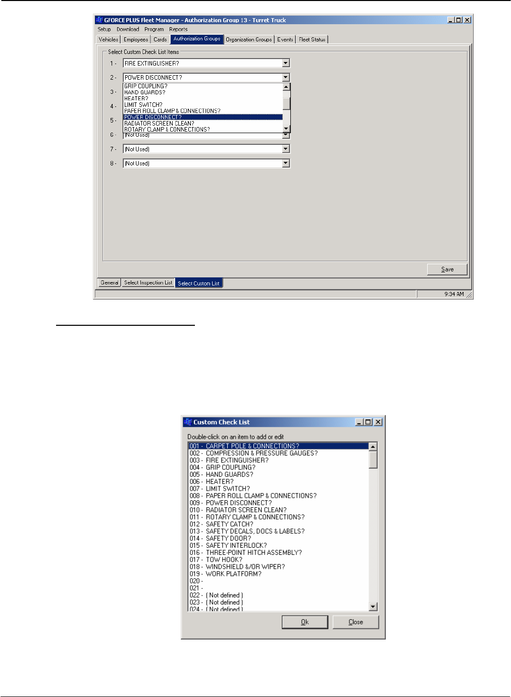
5. Click on the Select Custom List tab at the bottom of the Authorization Group tab.
6. Select up to 8 user-defined inspection items. These will appear on the Vehicle Interface in the
order selected from top to bottom after the selected system-defined items.
7. Click the [Save] button to save the Select Custom List tab changes.
G FORCE PLUS RF Instruction Manual
Apr/08 32 Doc #RF1 Rev.9
Edit the Custom Checklist
The Custom Checklist allows for an Authorization Group’s Vehicle Inspection Checklist to be
customized. The Software can store up to 200 fully editable user-defined items, and is preset with 18
common ones. To modify the list:
3. Select Setup | Custom Check List from the menu.
4. Double-click an item from the list to edit it, or double-click a [Not defined] line to add to the list.
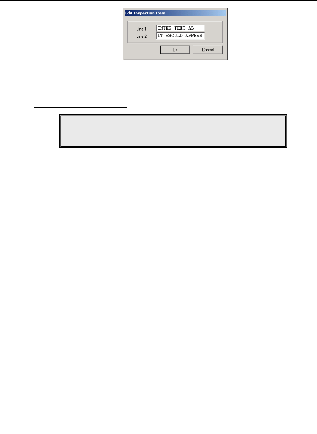
5. Type the text the way you want it to display on the 2x16-character LCD display of the Vehicle
Interface.
DRAFT G FORCE PLUS RF Instruction Manual
Doc #RF1 Rev.9 33 Apr/08
6. Click the [OK] button to add the item to the list.
7. Click the [OK] button to save the changes.
Edit an Authorization Group
1. Select the Authorization Groups | General tab.
2. Select the Authorization Group you want to edit from the grid.
3. Click the [Edit] button to open the “Edit Authorization Group” window.
4. HINT: Double-click an Authorization Group from the grid to save a step!
5. Change the desired field on the General, Settings or Vehicle Defaults tab.
6. Click the [OK] button to save the changes.
NOTE!
Changes to the settings of an Authorization Group require all Vehicles in the
Authorization Group to be reprogrammed with the Data Logger.

G FORCE PLUS RF Instruction Manual
Apr/08 34 Doc #RF1 Rev.9
Vehicles
The details and desired settings of each Vehicle equipped with a Vehicle Monitor must be added to the
Fleet Manager Software and linked to one Authorization Group. The Authorization Group to which the
Vehicle is assigned is used to determine vehicle access by Operator Card validation, as well as the
Inspection Checklist that will display on the Vehicle Interface.
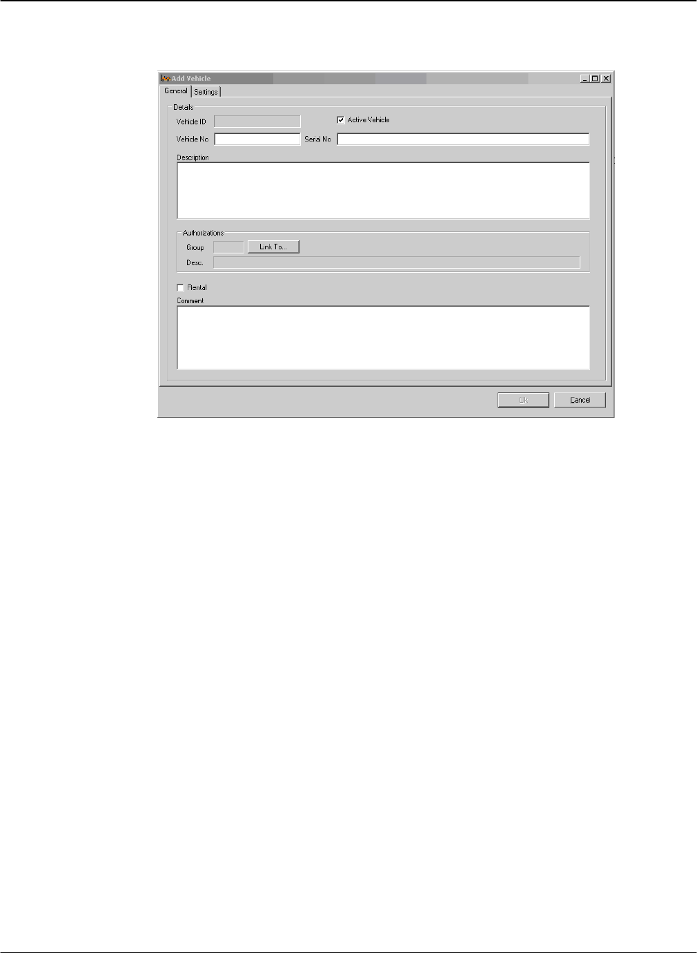
Add a Vehicle
1. Select the Vehicles | General tab.
2. Click the [Add] button to open the “Add Vehicle” window. Settings are explained in the section
“
NOTE!
Authorization Groups must be set up before Vehicles and Employees.
DRAFT G FORCE PLUS RF Instruction Manual
Doc #RF1 Rev.9 35 Apr/08
DATA FIELD DEFINITIONS”.
3. Complete the fields on the General tab.
Vehicle No.: The unique vehicle identifier.
Serial No.: The vehicle serial number.
Description: A description of the truck that will appear in reports.
G FORCE PLUS RF Instruction Manual
Apr/08 36 Doc #RF1 Rev.9
Click the [Link To…] button to open the “Assign Authorization Group” window. Select
an Authorization Group from the grid and click the [OK] button.
4. If the truck requires different settings from the defaults for its Authorization Group, complete the
fields on the Settings tab.
5. Click the [OK] button to save the changes.
Edit a Vehicle
1. Select the Vehicles | General tab.
2. Select the Vehicle you want to edit from the grid.
3. Click the [Edit] button to open the “Edit Vehicle” window.
4. HINT: Double-click a Vehicle from the grid to save a step!
5. Change the desired field on the General or Settings tab.
6. Click the [OK] button to save the changes.
NOTE!
Changes to the settings of a Vehicle require the
Vehicle Monitor to be reprogrammed with the Data Logger.
DRAFT G FORCE PLUS RF Instruction Manual
Doc #RF1 Rev.9 37 Apr/08
Employees
The following Employees must be entered in the Fleet Manager Software. Cards are assigned to each
Employee based on role. An Employee may require more than one Card:
Employees operating Vehicles for the purpose of materials handling Æ Operator Card
Employees responsible for investigating Impact or Hot Card alarms Æ Supervisor Card
Employees responsible for Vehicle and battery maintenance Æ Lockout and Unlock Cards
Add an Employee
1. Select the Employees | General tab.
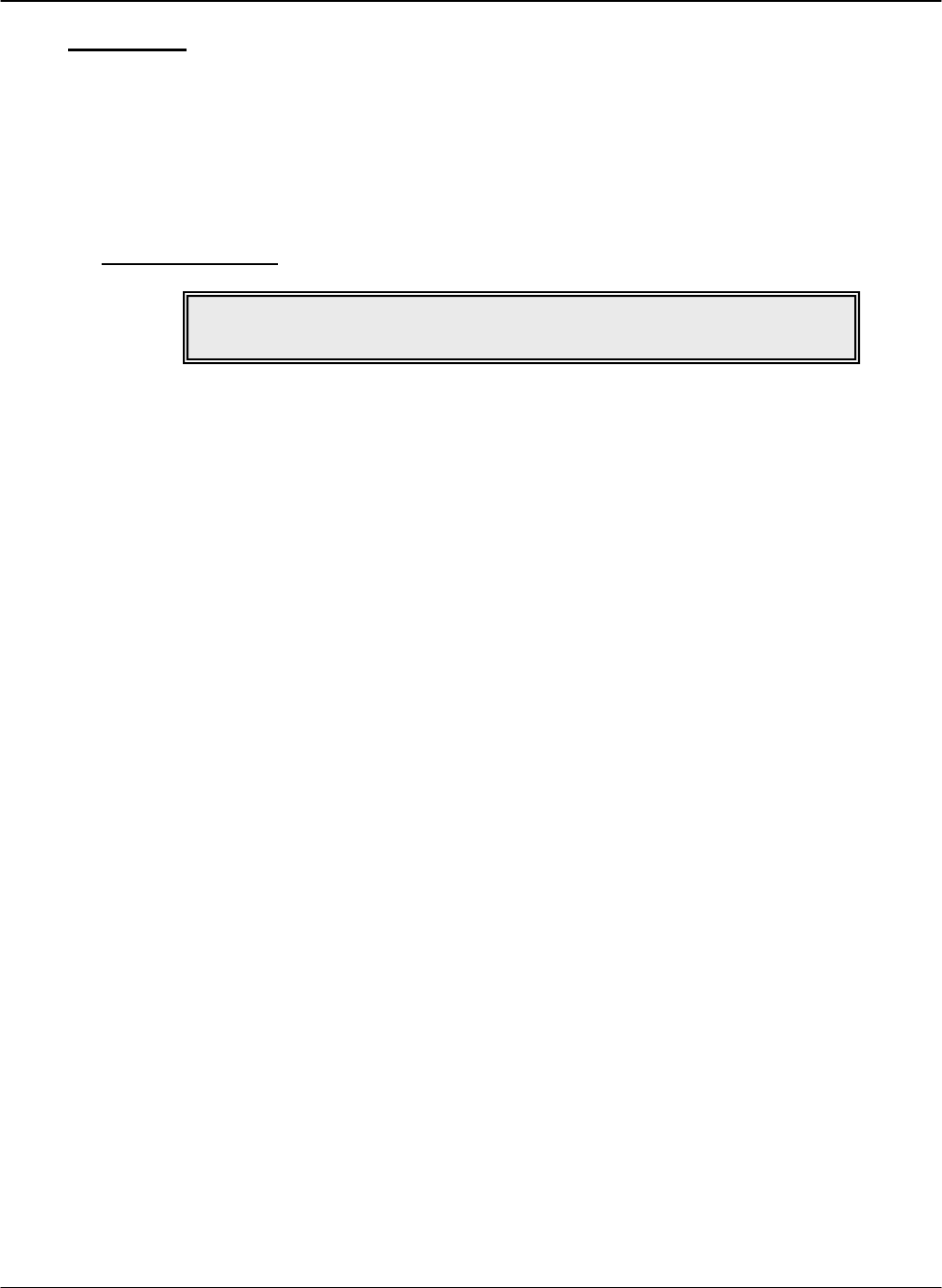
2. Click the [Add] button to open the “Add Employee” window. Fields are explained in the section
“
NOTE!
Authorization Groups must be set up before Vehicles and Employees.
G FORCE PLUS RF Instruction Manual
Apr/08 38 Doc #RF1 Rev.9
DATA FIELD DEFINITIONS”.
3. Complete the Add Employee fields and click the [OK] button to save the changes.
4. Define vehicle access rules for the Operator by clicking (see “Define Vehicle Access Rules for an
Operator”).
5. All operators must be assigned 1Authorization Group at creation by clicking the Link To…
button.
6. Assign a Card to the Employee (see “CARD ASSIGNMENT”).
Define Vehicle Access Rules for an Operator
Vehicle access rules must be set up for Employees who will be operating Vehicles equipped with
Vehicle Monitors. This is done through the assignment of Authorization Groups to the Operator, and
in the case of exceptions to this, through the assignment of single Vehicles to the Operator.
These assignments are written to an Operator Card, and when presented to a Vehicle Interface, it is
determined if there is a match between the Operator Card and the Authorization Group to which a
Vehicle belongs (or a match to the Vehicle itself in the case of Single Vehicle assignments).
1. Select the Employees tab.
2. Select the desired Employee from the grid.
3. Assign Authorization Groups to the Operator.
DRAFT G FORCE PLUS RF Instruction Manual
Doc #RF1 Rev.9 39 Apr/08
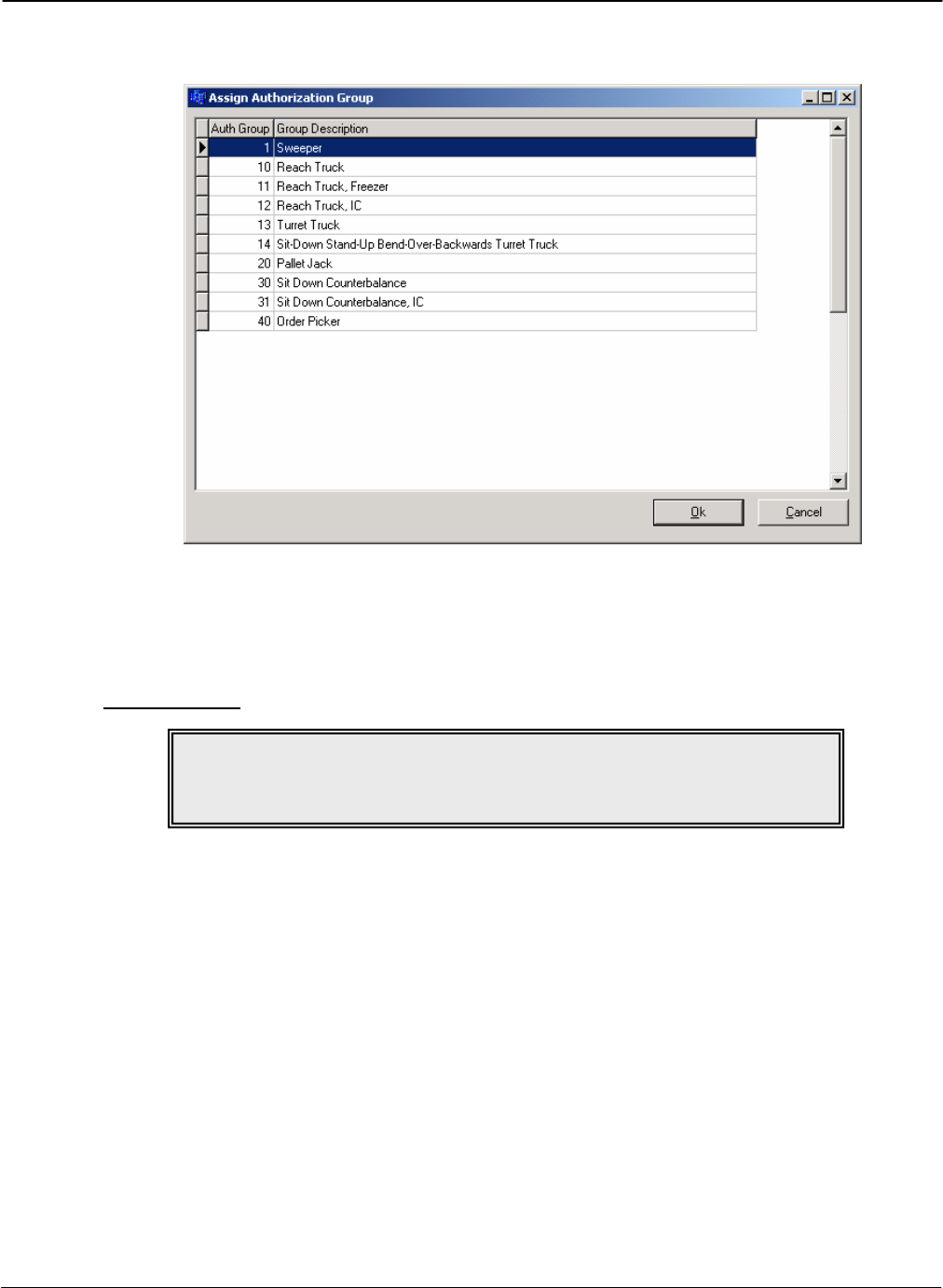
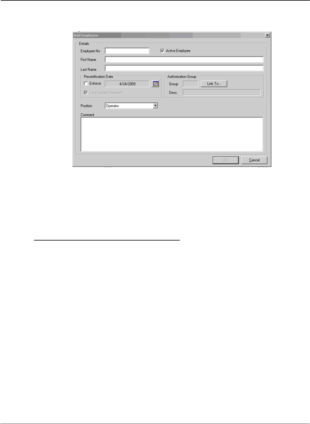
a. Click the Employees | Assign Authorization Groups tab.
b. Click the [Add] button to open the “Assign Authorization Group” window.
c. Select an Authorization Group from the grid.
d. Click the [OK] button to save the addition.
e. HINT: Double-click an Authorization Group to save a step!
4. Repeat until all Authorization Groups for the Operator are shown on the Employees | Assign
Authorization Groups tab.
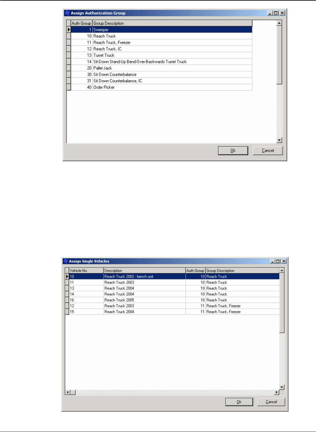
5. Assign Single Vehicles to the Operator where Authorization Group assignments do not apply (for
example, to keep an Operator-in-training off new vehicles).
a. Click the Employees | Assign Single Vehicles tab.
G FORCE PLUS RF Instruction Manual
Apr/08 40 Doc #RF1 Rev.9
b. Click the [Add] button to open the “Assign Single Vehicles” window.
c. Select a Vehicle from the grid.
d. Click the [OK] button to save the addition.
e. HINT: Double-click a Vehicle to save a step!
6. Repeat until all Vehicles for the Operator are shown on the Employees | Assign Single Vehicles
tab.
7. Delete Authorization Group or Single Vehicle assignments by using the [Delete] button on the
“Assign Authorization Groups” and “Assign Single Vehicles” windows.
Edit an Employee
1. Select the Employees tab.
2. Change the Employee’s general details if required.
a. Select the Employee you want to edit from the grid.
b. Click the [Edit] button to open the “Edit Employee” window.
c. HINT: Double-click an Employee from the grid to save a step!
d. Change the desired field.
e. Click the [OK] button to save the changes.
3. Change the Employee’s Authorization Group assignments if required.
a. Select the Employee you want to edit from the grid.
b. Select the Employees | Assign Authorization Groups tab.
c. Click the [Add] or [Delete] button to add or delete Authorization Groups until the Employees
| Assign Authorization Groups tab shows the desired Authorization Group assignments.
4. Change the Employee’s single Vehicle assignments if required.
a. Select the Employee you want to edit from the grid.
b. Select the Employees | Assign Single Vehicles tab.
c. Click the [Add] or [Delete] button to add or delete Vehicles until the Employees | Assign
Single Vehicles tab shows the desired Vehicle assignments.
5. Update the Employee’s Operator Card if required (see CARD ASSIGNMENT).
Transceivers
Data is communicated from an RF Vehicle Monitor-equipped Vehicle to the Fleet Manager Software by
way of a network of RF Transceivers. The RF Host Transceiver is physically connected to the PC
running the Fleet Manager Software and other RF Transceivers (Zone Transceivers) are each placed
within range of the Host Transceiver.
While the Fleet Manager Software automatically detects the presence of the RF Transceivers once the
Host Transceiver is connected to the PC, their identification within the Software can be customized for
display on the Fleet Status tab if desired.
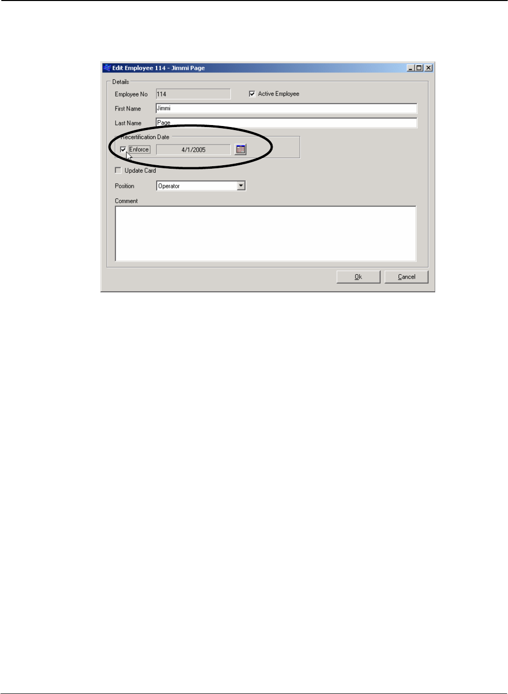
NOTE!
Recertification Date and vehicle access rule changes for Operators require
the Employee’s Operator Card to be updated.
DRAFT G FORCE PLUS RF Instruction Manual
Doc #RF1 Rev.9 41 Apr/08
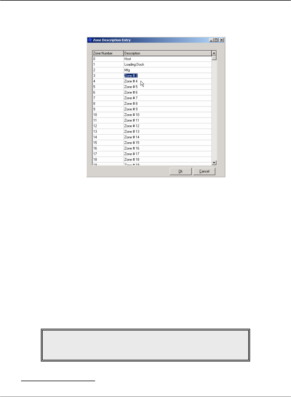
1. Select Setup | Zone Description… from the menu to open the “Zone Description Entry” window.
The Zone Description defaults are “Zone # 0”, “Zone # 1”, “Zone # 2”, etc.
2. Click on the desired Description to highlight the text.
3. Rename the Zone Description to match the physical location of the selected Zone Transceiver. Each
Zone Transceiver is labeled with its factory-assigned Zone Number.
4. Click the [OK] button to save the changes.
5. It is recommended to name the Host Transceiver (Zone # 0) as “Host”.
6. The new Description will be used to identify the Last Zone for each Vehicle on the Fleet Status tab.
CARD ASSIGNMENT
After Employees are entered in the Fleet Manager Software, they are assigned Cards that are read by the
Vehicle Interface of each Vehicle. Cards are assigned to each Employee based on the role of the Employee.
An Employee may require more than one Card:
Employees operating Vehicles for the purpose of materials handling Æ Operator Card
Employees responsible for investigating Impact or Hot Card alarms Æ Supervisor Card
Employees responsible for Vehicle and battery maintenance Æ Lockout and Unlock Cards
Set a Card Expiry Date
NOTE!
Employees who will be assigned Operator Cards must have
vehicle access rules defined.
G FORCE PLUS RF Instruction Manual
Apr/08 42 Doc #RF1 Rev.9
There are two ways to determine how a Card can expire:
By enforcing an Employee’s Recertification Date. This date applies only to Operator Cards.
By setting a Card’s Expiry Date (see below). This is done at the time of Card assignment and can
apply to all Card types. For example, it can be used for Operator Cards assigned to temporary
employees or for Supervisor Cards to ensure timely Impact Event data collection in a G FORCE
PLUS system.

DRAFT G FORCE PLUS RF Instruction Manual
Doc #RF1 Rev.9 43 Apr/08
Assign a Card
Follow steps 2 to 9 for initial Card assignment, as well as for updating Cards or reassigning them to new
Employees.
1. Select the Cards tab.
2. Place a Card on the Software Interface.
3. Click the [Write] button to open the “Write to Card” window. The Software recognizes and displays
the Card serial number and type, and the Employee if the Card is being updated.
4. Enter a Card Expiry Date if required (for example, for temporary Employees). Setting a Card’s
Expiry Date renders it unusable on or after that date. This applies to all Card types.
a. Check the Enforce checkbox.
b. Click the [] button (Calendar) to select the date.
c. Click the [OK] button to close the “Select Date” window.
5. Select the Employee to assign the Card to.
a. Click the [Link To…] button to open the “Select Employee” window.
G FORCE PLUS RF Instruction Manual
Apr/08 44 Doc #RF1 Rev.9
b. Select an Employee from the grid.
c. Click the [OK] button to save the change.
d. HINT: Double-click an Employee to save a step!
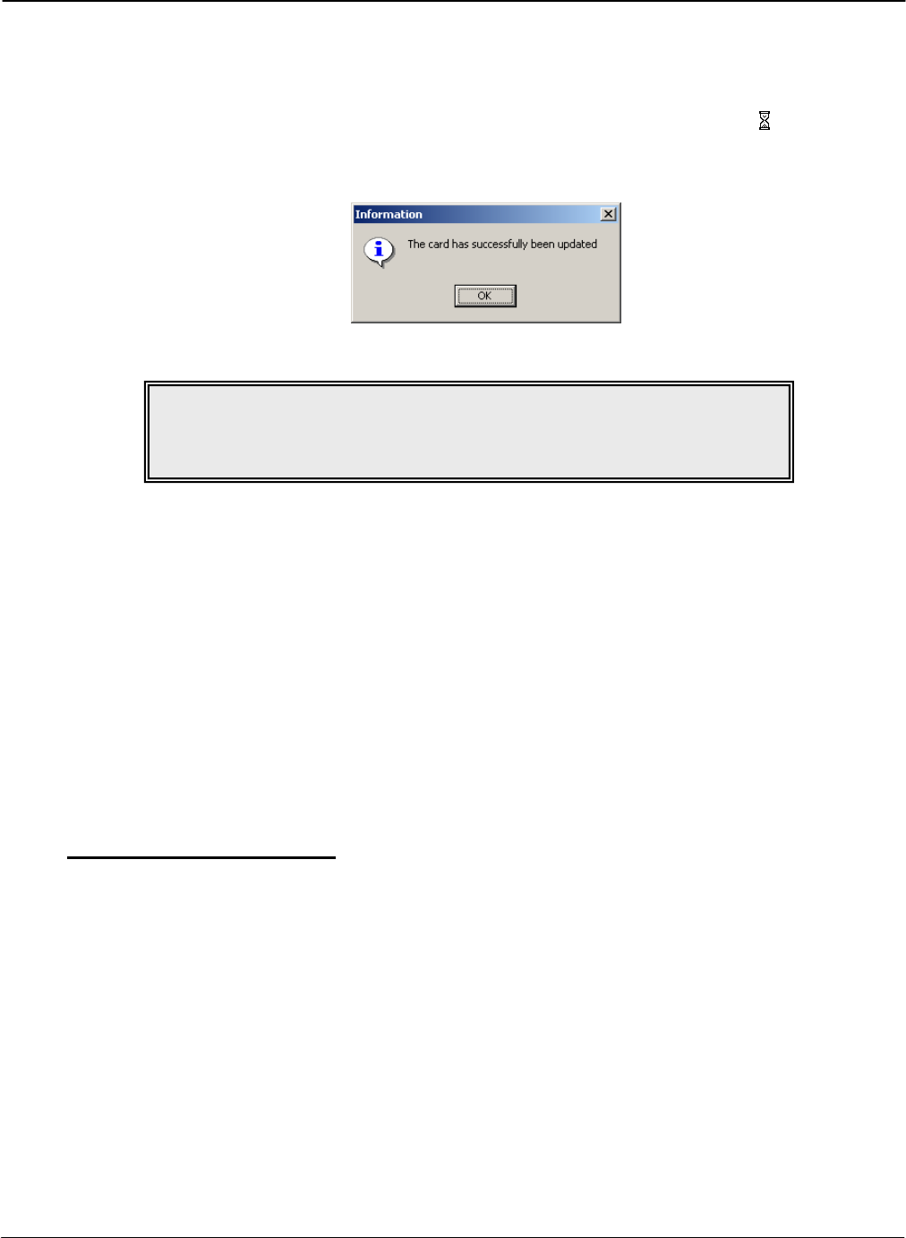
6. Click the [Program Card] button. The mouse-pointer will turn into an hourglass ( ) while the
details are being written to the Card.
7. Click the [OK] button to close the window that indicates the Card has been updated.
8. Remove the Card from the Software Interface and give it to the Employee.
VEHICLE MONITOR
Each Vehicle that is added to the Fleet Manager Software is assigned a system-defined identification number
(ID). This ID is different than the company-assigned identification number (Vehicle No). This ID uniquely
identifies the Vehicle within the system and must be programmed to the Vehicle Monitor to draw a
connection between it and its entry in the Software.
In addition, settings for each Vehicle are maintained in the Software. These settings determine a Vehicle’s
unique behavior and must also be programmed from the Software to the Vehicle Monitor.
The Data Logger is used for both these programming tasks.
Initialize a Vehicle Monitor
The first time a Vehicle Monitor is installed on a Vehicle, it needs to be initialized. This is when both the
Vehicle ID and settings from the Software are programmed.
The Data Logger can initialize up to 9 (nine) Vehicle Monitors at a time; it has 9 (nine) memory slots for
Vehicle IDs and 9 (nine) memory slots for Vehicle settings.
1. Get the Vehicle ID for the selected Vehicle.
a. Press {Enter} on the Data Logger to start it.
b. Press {2} when the Data Logger displays “Action?(1-9)”. The Data Logger will display
“Action?(1-9) Get Vehicle ID”
c. Press {Enter} to accept the choice. The Data Logger will display “Select Slot:”
d. Press {1} to select slot #1. The Data Logger will display “Select Slot: 1 Free”
e. Press {Enter} to accept the choice. The Data Logger will display “Select Slot: 1 Slot 1 Ready”
NOTE!
Don’t throw a Card away if an Employee quits.
Reuse it by linking a new Employee to it.
DRAFT G FORCE PLUS RF Instruction Manual
Doc #RF1 Rev.9 45 Apr/08
f. Present the Data Logger to the Software Interface.
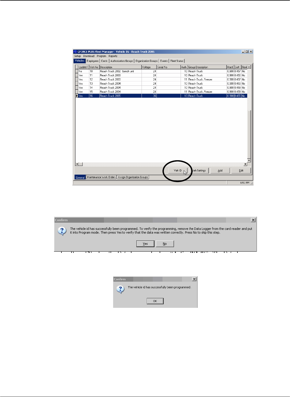
g. Select the desired Vehicle from the Vehicles tab of the Fleet Manager Software and click the
[Veh ID] button. The status bar at the bottom left of the Software will provide progress
information (“Programming vehicle id…”). When it finishes, the Data Logger will display “All
Data Saved”.
h. This window will appear. If you wish to confirm the ID was programmed, on the Data Logger
press {Cancel}, then press {5}, {Enter}, {1}, {Enter} and present the Data Logger to the
Software Interface, then click the [Yes] button. To skip this step, press [No]
i. If you chose to confirm the ID, this window will appear. The Data Logger will display “All Data
Prog’d”.
j. Remove the Data Logger from the Software Interface and press {Cancel}. The Data Logger will
display “Action?(1-9)”
2. Record the memory slot used for the selected Vehicle.
3. Get the Vehicle settings for the selected Vehicle.
a. Press {Enter} to start the Data Logger.
b. Press {3} when the Data Logger displays “Action?(1-9)”. The Data Logger will display
“Action?(1-9) Get Veh Settings”
G FORCE PLUS RF Instruction Manual
Apr/08 46 Doc #RF1 Rev.9
c. Press {Enter} to accept the choice. The Data Logger will display “Select Slot:”
d. Press {1} to select slot #1. The Data Logger will display “Select Slot: 1 Free”
e. Press {Enter} to accept the choice. The Data Logger will display “Select Slot: 1 Slot 1 Ready”
f. Present the Data Logger to the Software Interface.
g. Select the same Vehicle from the Vehicle tab of the Fleet Manager Software and click the [Veh
Settings] button. The status bar at the bottom left of the Software will provide progress
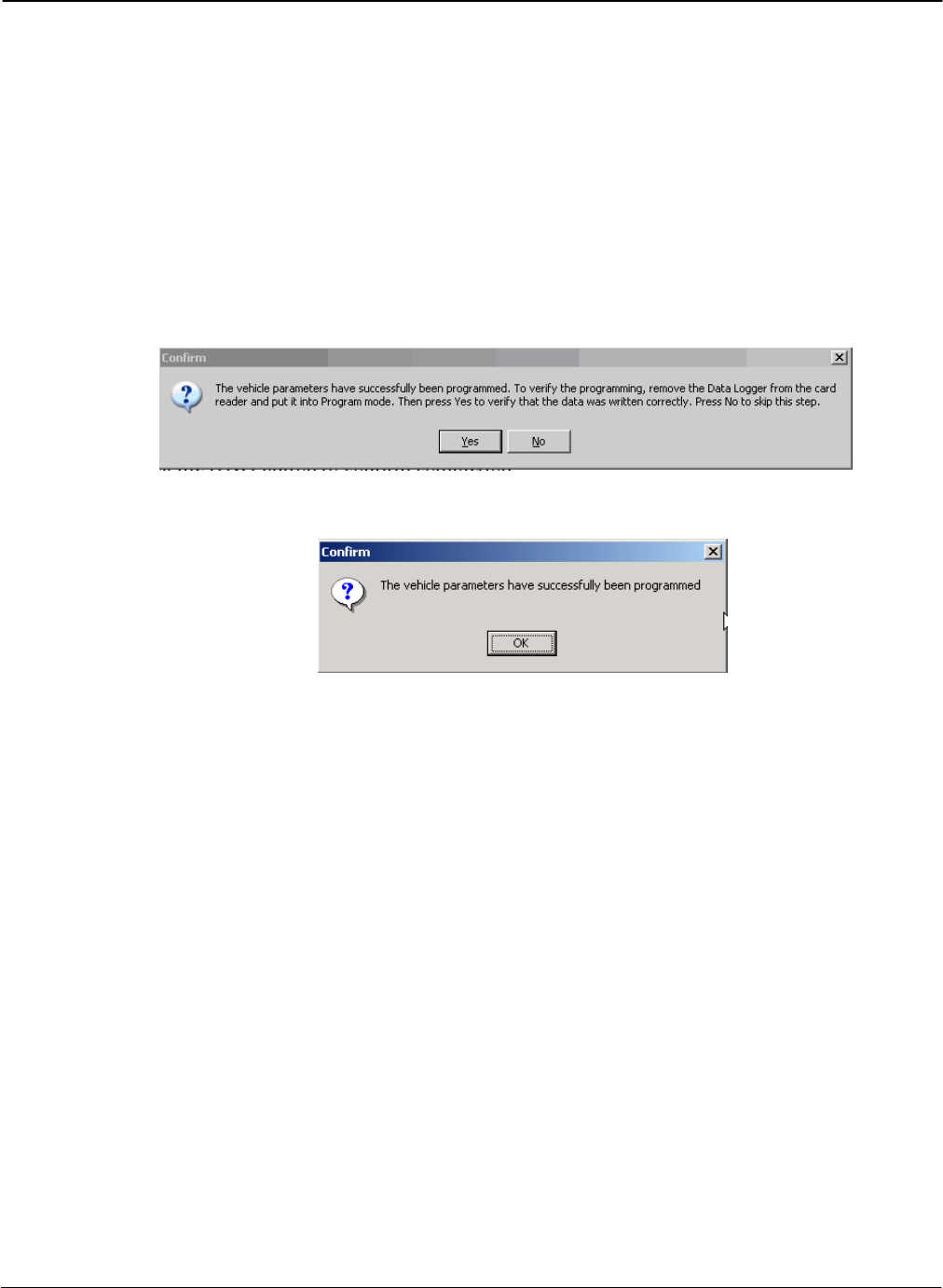
information (“Programming vehicle parameters…” etc).
h. When it is complete, this window will appear. If you wish to confirm the Settings were
programmed, on the Data Logger press {Cancel}, then press {6}, {Enter}, {1}, {Enter} and
present the Data Logger to the Software Interface, then click the [Yes] button. To skip this step,
click the [No] button.
i. If you chose to confirm the settings, this window will appear. Click the [OK] button to confirm
completion.
j. Remove the Data Logger from the Software Interface and press {Cancel}. The Data Logger will
display “Action?(1-9)”
4. Repeat steps 1 to 3 for up to 8 (eight) more Vehicles, working through memory slots 2 to 9 and
recording the memory slot used for each Vehicle.
5. Place the Vehicle from memory slot #1 into Maintenance Lockout.
6. Program the Vehicle ID to the Vehicle Monitor.
a. Press {Enter} to start the Data Logger.
b. Press {5} when the Data Logger displays “Action?(1-9)”. The Data Logger will display
“Action?(1-9) Prog Veh ID”
c. Press {Enter} to accept the choice. The Data Logger will display “Select Slot:”
d. Press {1} to select slot #1. The Data Logger will display “Select Slot: 1 Has Data”
e. Press {Enter} to accept the choice. The Data Logger will display “Select Slot: 1 Ready”
f. Present the Data Logger to the Vehicle Interface.
g. Listen for a sequence of three quick beeps to indicate the interaction is complete.
h. Remove the Data Logger from the Vehicle Interface. The Vehicle Interface will display
“VEHICLE ID UPDATED”.
i. Press {Cancel} on the Data Logger. The Data Logger will display “Action?(1-9)”.
7. Program the Vehicle settings to the Vehicle Monitor.
a. Press {Enter} to start the Data Logger.

DRAFT G FORCE PLUS RF Instruction Manual
Doc #RF1 Rev.9 47 Apr/08
b. Press {6} when the Data Logger displays “Action?(1-9)”. The Data Logger will display
“Action?(1-9) Prog Veh Settngs”
c. Press {Enter} to accept the choice. The Data Logger will display “Select Slot:”
d. Press {1} to select slot #1. The Data Logger will display “Select Slot: 1 Has Data”
e. Press {Enter} to accept the choice. The Data Logger will display “Select Slot: 1 Ready”
f. Present the Data Logger to the Vehicle Interface.
g. The Data Logger will display “Progging Data:” and then 33%, 66%, and “All Data Prog’d”.
h. Listen for a sequence of three quick beeps to indicate the interaction is complete.
i. Remove the Data Logger from the Vehicle Interface. The Vehicle Interface will display
“PROGRAMMING SETTINGS COMPLETE”
j. Press {Cancel} on the Data Logger. The Data Logger will display “Action?(1-9)”.
8. Remove the selected Vehicle Monitor from Maintenance Lockout.
9. Repeat steps 5 to 8 for the remaining Vehicles, matching the recorded Vehicles and memory slots.

G FORCE PLUS RF Instruction Manual
Apr/08 48 Doc #RF1 Rev.9
Update Vehicle Monitor Settings
Each time there is a change to the Vehicle settings in the Fleet Manager Software, the Data Logger must
be used to update, or reprogram, the Vehicle Monitor settings of the affected Vehicle(s).
1. Program the Vehicle settings for the selected Vehicle to the Data Logger.
2. Record the memory slot for the selected Vehicle.
3. If required, repeat steps 1 and 2 for up to 8 (eight) more Vehicles.
4. Place the selected Vehicle Monitor into Maintenance Lockout.
5. Reprogram the Vehicle settings of the Vehicle Monitor for the selected Vehicle.
6. Remove the selected Vehicle Monitor from Maintenance Lockout.
7. If required, repeat steps 4 to 6 for the remaining Vehicles.
NOTE!
When changes are made to System Settings and Authorization Groups, all or
many Vehicle Monitors may require updating.
DRAFT G FORCE PLUS RF Instruction Manual
Doc #RF1 Rev.9 49 Apr/08
VEHICLE OPERATION
The sections below describe the various states, conditions and operating requirements of a Vehicle equipped with
a Vehicle Monitor.
VEHICLE STARTUP
1. Turn the Vehicle ignition on.
2. If the Vehicle requires a Diagnostic Delay (setting from the Vehicle’s Authorization Group), the Vehicle
Interface will display “VEHICLE SYSTEM CHECK PLS WAIT..”.
3. The Vehicle Interface will display “OPERATOR LOGIN PRESENT CARD” after the expiry of the
Diagnostic Delay.
OPERATOR LOGIN
1. Present a valid Operator Card to the Vehicle Interface when it displays “OPERATOR LOGIN
PRESENT CARD”. This message will alternate with “BATTERY (STATE OF CHARGE)” if the
Vehicle’s Authorization Group settings require Battery Monitoring.
2. If no Operator Card is presented within three seconds, the Vehicle Interface buzzer will sound, as will the
horn if programmed to do so.
3. The Vehicle Interface will indicate a Card has been validated with a single beep, or by stopping the
sounding buzzer (and horn).
4. Remove the Card from the Vehicle Interface. It will display “LOGIN APPROVED”. “LOGIN
APPROVED CARD EXPIRY SOON” will display if the System Settings indicate a Card Expiration
Warning is required.
Messages other than “LOGIN APPROVED” indicate why a Card could not be validated. The Vehicle
Interface reverts to “OPERATOR LOGIN PRESENT CARD” after five seconds.
“LOGIN DECLINED CARD INVALID” Not an Operator or Lockout Card
G FORCE PLUS RF Instruction Manual
Apr/08 50 Doc #RF1 Rev.9
“LOGIN DECLINED CARD EXPIRED” Expired Operator or Lockout Card, or Operator Card
with an expired Recertification Date
“LOGIN DELINED NOT AUTHORIZED” Operator Card with wrong Authorization Group or
Single Vehicle assignments, or unassigned Operator
Card
VEHICLE INSPECTION
1. Press {Yes} on the Vehicle Interface when it displays “VEH INSPECTION YES TO START” The
Vehicle Interface will display the first item on the list as defined in the Authorization Group for the
Vehicle. The Vehicle Interface will revert to “OPERATOR LOGIN PRESENT CARD” if {No} or
{Cancel} is pressed.
2. Conduct the necessary test (i.e. visual inspection or operation of controls) to determine if the item should
pass or fail.
3. Press {Pass} on the Vehicle Interface to indicate the item has passed. The Vehicle Interface will display
the next item on the list as defined in the Authorization Group for the Vehicle. Repeat steps 2 and 3 until
the Vehicle Interface displays “VEH INSPECTION COMPLETE, PASSED”, OR
4. Press {Fail} on the Vehicle Interface to indicate the item has failed. The Vehicle Interface will display
“VEH INSPECTION FAILURE? YES/NO”
5. Press {Yes} to confirm the failure of the Vehicle Inspection. The Vehicle Interface will display “MAINT
LOCK OUT YYYY/MM/DD HH:MM” to indicate it is in Maintenance Lockout, OR
6. Press {No} to cancel the failure of the Vehicle Inspection. The Vehicle Interface will display the item in
question again and wait for a {Pass} or {Fail} key press.
7. The Vehicle Interface will revert to “OPERATOR LOGIN PRESENT CARD” if {Cancel} is pressed
in response to any Vehicle Inspection item.
8. The Vehicle Interface will revert to “OPERATOR LOGIN PRESENT CARD” if there is no keypad
response from the Operator within the period of time determined by the Vehicle Inspection Inactivity
Timer under the System Settings.
OPERATING
1. A Vehicle enters Operating state after a Passed Vehicle Inspection, or after a successful Operator Login if
no Vehicle Inspection was required. The Vehicle Interface will display “OPERATING MODE”. This
message will alternate with “BATTERY (STATE OF CHARGE)” if the Authorization Group of the
Vehicle requires Battery Monitoring.
2. Key-off the Vehicle to end the Login session for the current Operator.

DRAFT G FORCE PLUS RF Instruction Manual
Doc #RF1 Rev.9 51 Apr/08
3. A new Operator must restart the Vehicle in order to have his/her Operator Card validated in the Operator
Login state.
IMPACT
1. If a threshold-exceeding Impact is detected, the Vehicle enters Impact state.
a. The Vehicle Interface buzzer will sound (1 second every 2 seconds), or
b. The Vehicle Interface buzzer and horn will sound as programmed under System Settings, and
c. Programmed Impact behavior (i.e. lift interrupt, etc.) will exhibit, and
d. The Vehicle Interface will display “(TYPE) IMPACT! CONTACT SUPERVSR”, where (TYPE) is
SOFT or HARD.
2. Present a valid Supervisor Card to the Vehicle Interface and hold it until the Vehicle Interface beeps
solidly.
3. Remove the Card from the Vehicle Interface. It will display “OPERATOR LOGIN PRESENT
CARD”.
4. A Vehicle keyed off in Impact state will revert to Impact state when it is keyed on.
HOT CARD
1. If a Hot Card is detected during the Operator Login, the Vehicle enters Hot Card state.
a. The Vehicle Interface buzzer will sound, or
b. The Vehicle Interface buzzer and horn will sound as programmed under System Settings, and
c. Programmed Hot Card behavior (i.e. lift interrupt, etc.) will exhibit, and
d. The Vehicle Interface will display “HOT CARD! CONTACT SUPERVSR”.
2. Present a valid Supervisor Card to the Vehicle Interface and hold it until the Vehicle Interface stops
sounding.
3. Remove the Card from the Vehicle Interface. It will display “OPERATOR LOGIN PRESENT
CARD”.
4. A Vehicle keyed off in Hot Card state will revert to Hot Card state when it is keyed on.
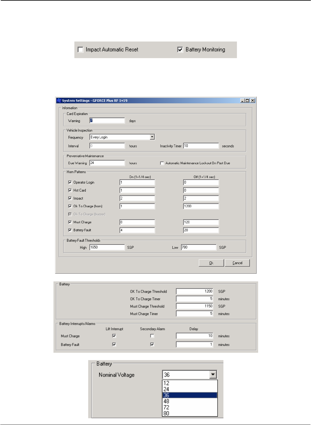
G FORCE PLUS RF Instruction Manual
Apr/08 52 Doc #RF1 Rev.9
BATTERY MONITORING
Batteries are monitored for Vehicles belonging to Authorization Groups where Battery Monitoring is required.
Criteria for Battery Monitoring are based on System Settings (Horn Patterns and Fault Thresholds), Authorization
Group settings (Thresholds, Interrupts/Alarms and Interrupt/Alarm Delays), and Vehicle settings (Nominal
Voltage: 12v, 24v, 36v, 48v)

DRAFT G FORCE PLUS RF Instruction Manual
Doc #RF1 Rev.9 53 Apr/08
Based on the settings, the Vehicle Monitor measures the voltage of the Vehicle’s battery and determines which of
four battery states the Vehicle Interface displays.
DO NOT CHARGE
Charging in the Do Not Charge state increases water consumption, wastes energy, and reduces battery life.
When the battery meets the criteria for Do Not Charge, the Vehicle Interface displays “BATTERY DO NOT
CHARGE” and the Battery Charge LED is green.
OK TO CHARGE
Charging in the Ok To Charge state produces good lifetime battery capacity.
When the battery meets the criteria for OK To Charge, the Vehicle Interface displays “BATTERY OK TO
CHARGE” and the Battery Charge LED is amber.
Audible alarms for the OK To Charge state are defined in the System Settings and include:
No alarm for OK To Charge, or
Vehicle Interface buzzer only (½-second every 60 seconds), or
Vehicle Interface buzzer and horn (alarm pattern as determined by System Settings)
MUST CHARGE
Charging in the Must Charge state produces maximum lifetime battery capacity, the greatest number of shifts
per charge, and the lowest per ampere charging costs.
When the battery meets the criteria for Must Charge, the Vehicle Interface displays “BATTERY MUST
CHARGE!” and the Battery Charge LED flashes red. The buzzer sounds for 2 seconds every 30 seconds.
Audible alarms for the Must Charge state are defined in the System Settings and include:
Vehicle Interface buzzer only (2 seconds every 15 seconds), or
Vehicle Interface buzzer and horn (alarm pattern as determined by System Settings)
Vehicle behavior for the Must Charge state is defined under Authorization Group settings and includes:
No specific behavior, or
Immediate lift interrupt and/or secondary alarm, or
Delayed lift interrupt and/or secondary alarm (delay as determined by Authorization Group settings)
NOTE!
Contact Technical Assistance at BMI Technologies Inc. at 1-800-563-8867
for assistance in determining optimal Battery settings for
each Authorization Group.
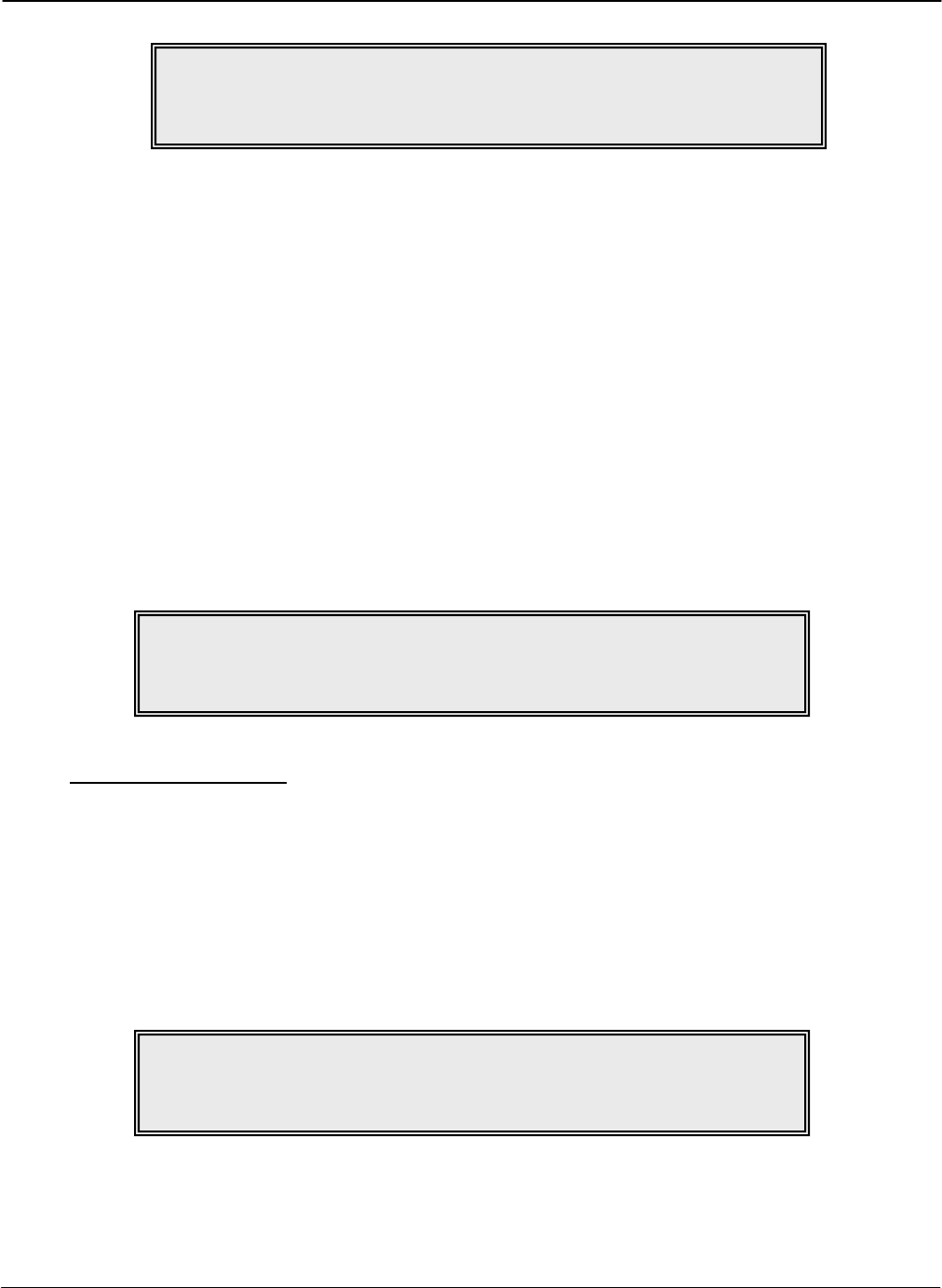
G FORCE PLUS RF Instruction Manual
Apr/08 54 Doc #RF1 Rev.9
BATTERY FAULT
The Battery Fault state alerts an Operator to a battery problem. Minor battery problems such as cell failure, a
bad inter cell connector, a broken battery post, and low water are detected before they become a major repair
expense.
When the battery meets the criteria for Battery Fault, the Vehicle Interface displays “BATTERY FAULT
OVER/UNDER VOLT.” and the Battery Fault LED is red.
Audible alarms for the Battery Fault state are defined in the System Settings and include:
Vehicle Interface buzzer only (1 second every 3 seconds), or
Vehicle Interface buzzer and horn (alarm pattern as determined by System Settings)
Vehicle behavior for the Battery Fault state is defined under Authorization Group settings and includes:
No specific behavior, or
Immediate lift interrupt and/or secondary alarm, or
Delayed lift interrupt and/or secondary alarm (delay as determined by Authorization Group settings)
Clear a Battery Fault
1. Place the Vehicle into Maintenance Lockout.
2. Disconnect the Vehicle battery.
3. Correct the battery problem or replace the battery.
4. Reconnect the Vehicle battery.
5. Remove the Vehicle from Maintenance Lockout (see “Remove a Vehicle from Lockout”).
6. If the Battery Fault alarm recurs, the further corrective steps.
NOTE!
Vehicle Monitor wiring must complement Vehicle settings
to exhibit programmed behavior.
NOTE!
Vehicle Monitor wiring must complement Vehicle settings
to exhibit programmed behavior.
NOTE!
A Battery Fault will occur when the Nominal Battery Voltage in Vehicle
Settings does not match the actual nominal battery voltage of the Vehicle.
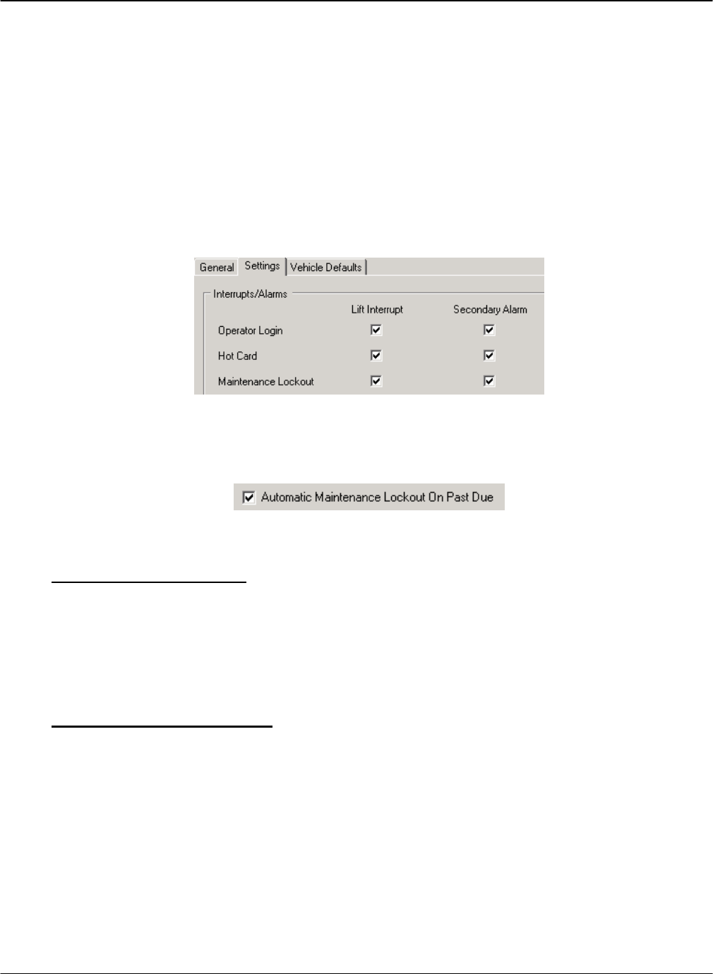
DRAFT G FORCE PLUS RF Instruction Manual
Doc #RF1 Rev.9 55 Apr/08
VEHICLE MAINTENANCE
This section on Vehicle Maintenance explains Maintenance Lockout as well as how to schedule Vehicle
Preventative Maintenance requirements.
MAINTENANCE LOCKOUT
Maintenance Lockout is one of eight possible Vehicle states. A Vehicle’s Maintenance Lockout behavior is
defined on the Settings tab of the Authorization Group of the Vehicle; that is, are the Lift Interrupt and
Secondary Alarm fields checked for Maintenance Lockout, and are the blue and purple wires correctly
hooked up?
There are three ways that a Vehicle can enter Maintenance Lockout state:
When an Operator fails a Vehicle Inspection
When a Vehicle’s scheduled PM is past due (the System Settings for this must also be checked)
When a Lockout Card is presented in Operator Login state
Why Lockout a Vehicle?
To reprogram a Vehicle’s settings, it must be in Maintenance Lockout
To collect Event data with a Data Logger, a Vehicle must be in Maintenance Lockout
To conduct scheduled Preventative Maintenance, a Vehicle must be in Maintenance Lockout
To make a Vehicle unavailable for service, it can be placed into Maintenance Lockout
Lockout a Vehicle Manually
1. Turn the Vehicle ignition on.
2. Present a Lockout Card to the Vehicle Interface when it displays “OPERATOR LOGIN PRESENT
CARD”
3. Remove the Card after the beep. The Vehicle Interface will display “MAINT LOCK OUT
YYYY/MM/DD HH:MM”
4. Present the Lockout Card a second time to override the Maintenance Lockout behavior. After key-
off, the programmed Maintenance Lockout behavior will again take effect.

G FORCE PLUS RF Instruction Manual
Apr/08 56 Doc #RF1 Rev.9
Override Maintenance Lockout Behavior
1. Present a Lockout Card to the Vehicle Interface when it displays “MAINT LOCK OUT
YYYY/MM/DD HH:MM”.
2. Remove the Card after the beep. The Vehicle Interface will display “HOURMETER XXXXXH”
“PM DUE IN: XXXXXH”.
3. Programmed Maintenance Lockout behavior (i.e. lift interrupt, etc.) will no longer exhibit.
4. After key-off, the programmed Maintenance Lockout behavior will again take effect.
Remove a Vehicle from Lockout
1. Turn the Vehicle ignition on.
2. Present an Unlock Card to the Vehicle Interface when it displays “MAINT LOCK OUT
YYYY/MM/DD HH:MM”.
3. Remove the Card after the beep. The Vehicle Interface will display “SCHEDULED PM
COMPLETE? YES/NO”.
4. Press {No} on the Vehicle Interface unless the Lockout was to conduct scheduled PM. The Vehicle
Interface will display “OPERATOR LOGIN PRESENT CARD”.
MAINTENANCE WORK ORDERS
It is possible to keep track of Vehicle maintenance by entering Maintenance Work Orders into the Software.
The reason for each Work Order is categorized as Impact, Scheduled PM, Failed Inspection or Other. This
allows the Software to report maintenance costs by these reasons.
Add a Work Order
1. Select the Vehicles tab.
2. Highlight (click) the Vehicle you want to add a Work Order for.
3. Click the Maintenance Work Orders tab at the bottom of the Vehicles tab.
4. Click the [Add] button to open the “Add Maintenance Work Order” window.
5. Complete the fields on the Work Order as per the field descriptions below.
Reference No Enter a Work Order number, or enter the reference number from the
paper copy of the shop Work Order.
Reason Select a reason the work was done: (1) Impact, (2) Scheduled PM,
(3) Failed Inspection, (4) Other.
Service Date Click the [] button (Calendar) to select the date of the Work
Order.
Service Hours Enter the Hour Meter reading of the Vehicle at the time the work was
completed.
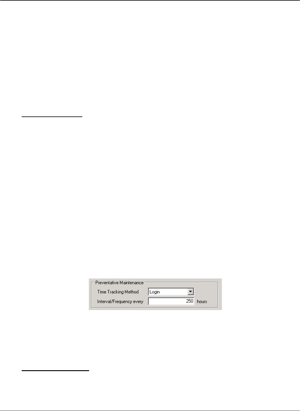
DRAFT G FORCE PLUS RF Instruction Manual
Doc #RF1 Rev.9 57 Apr/08
Impact Date and Employee If the Work Order reason is Impact or Failed Inspection, click the
[Link To…] button to select the event that caused the work to be
completed.
Service Technician Click the [Link To…] button to select the Service Technician who
completed the work.
Costing Enter the Parts and Labor Costs of the work completed.
Parts Description Enter a description of the Parts used to complete the work.
Comment Enter a Comment.
6. Click the [OK] button to save the changes.
Edit a Work Order
1. Select the Vehicles tab.
2. Highlight (click) the Vehicle you want to add a Work Order for.
3. Click the Maintenance Work Orders tab at the bottom of the Vehicles tab.
4. Highlight (click) the Work Order you want to edit.
5. Click the [Edit] button to open the “Edit Maintenance Work Order” window.
6. HINT: Double-click a Work Order from the grid to save a step!
7. Edit the fields as required.
8. Click the [OK] button to save the changes.
PREVENTATIVE MAINTENANCE
Vehicle Monitors can be scheduled to advise when regular Preventative Maintenance checks are required.
The Preventative Maintenance settings for each Authorization Group determine how often the checks are
required and how time is calculated (i.e. Login, Motion) for all Vehicles belonging to the Authorization
Group.
In the example above, when a Vehicle is initialized, its first scheduled Preventative Maintenance will be after
250 hours of Login time. After that, Preventative Maintenance checks are scheduled for 250 hours from the
Current Hour Meter reading. For example, if the PM is completed at 262 hours, the next PM will be required
at 512 hours.
PM Due Notification
The Preventative Maintenance System Settings determine if there is a warning that Preventative
Maintenance is due soon, as well as Vehicle behavior once Preventative Maintenance is due. These
settings apply to all Vehicles in the system.
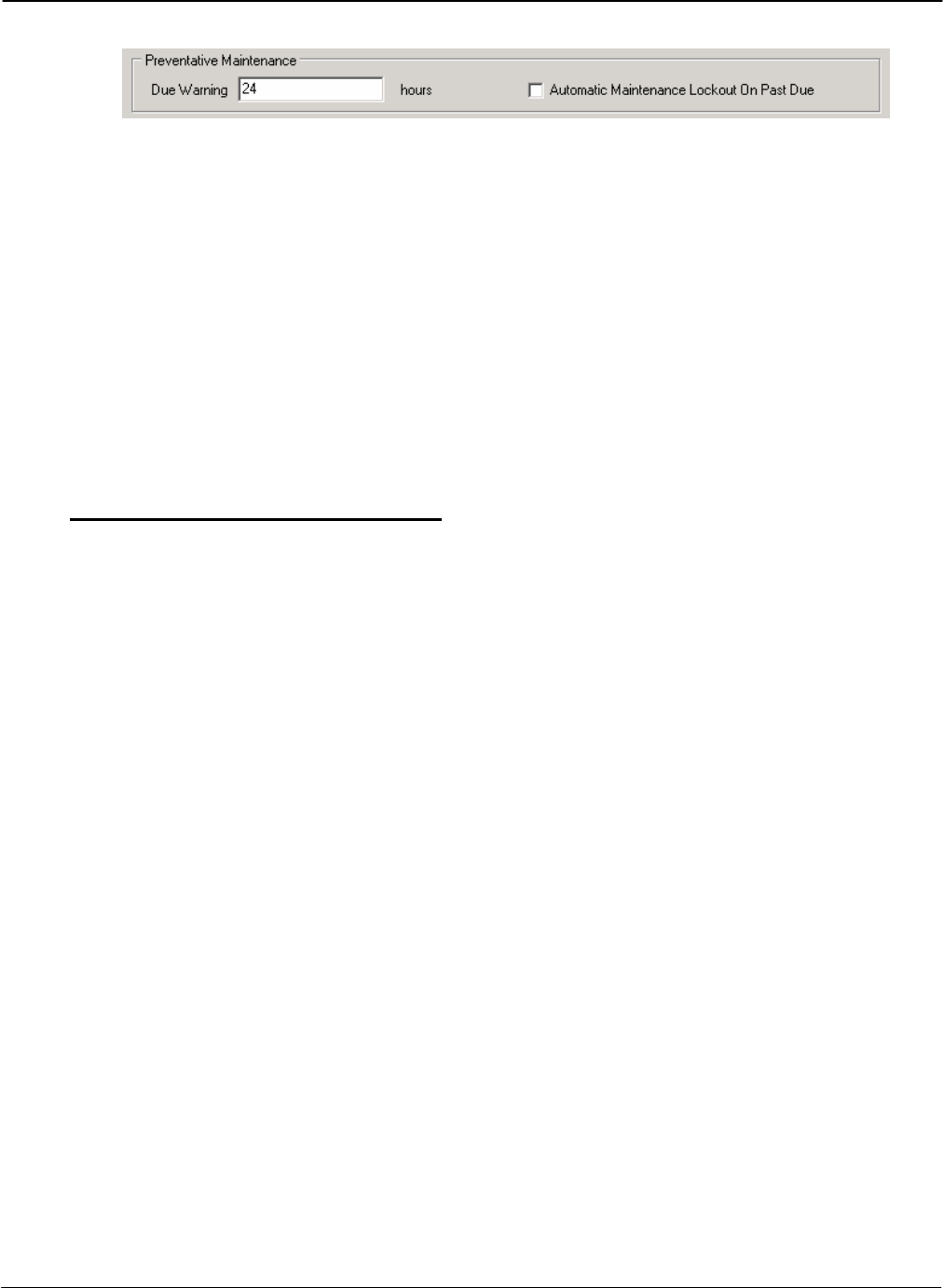
G FORCE PLUS RF Instruction Manual
Apr/08 58 Doc #RF1 Rev.9
In the example above, when Vehicle PM’s are due within 24 hours (of Login or Motion time), the Vehicle
Interface displays “OPERATOR LOGIN PM DUE SOON” during the Operator Login and
“OPERATING MODE PM DUE SOON” during Operating mode.
When PM’s become due after 24 hours, the Vehicle Interface displays “OPERATOR LOGIN PM DUE
NOW” during the Operator Login and “OPERATING MODE PM DUE NOW” during Operating
mode.
If the “Automatic Maintenance Lockout On Past Due” checkbox is checked, Vehicles enter Maintenance
Lockout at the next key-on after scheduled Preventative Maintenance is due. The Vehicle Interface
displays “MAINT LOCK OUT YYYY/MM/DD HH:MM” and the programmed Maintenance Lockout
behavior exhibits (i.e. lift interrupt, etc.). If the “Automatic Maintenance Lockout On Past Due”
checkbox is not checked, the Vehicle will remain operable.
Conduct Preventative Maintenance
Follow these steps for Preventative Maintenance to ensure proper record keeping in the Software:
1. Place the Vehicle into Maintenance Lockout.
2. Conduct the necessary Preventative Maintenance.
3. Remove the Vehicle from Maintenance Lockout as follows:
a. Turn the Vehicle ignition on.
b. Present an Unlock Card to the Vehicle Interface when it displays “MAINT LOCK OUT
YYYY/MM/DD HH:MM”.
c. Remove the Card after the beep. The Vehicle Interface will display “SCHEDULED PM
COMPLETE? YES/NO”.
d. Press {Yes} on the Vehicle Interface to schedule the next Preventative Maintenance. The Vehicle
Interface will display “OPERATOR LOGIN PRESENT CARD”.
4. Complete a Maintenance Work Order with Scheduled PM selected as the reason.
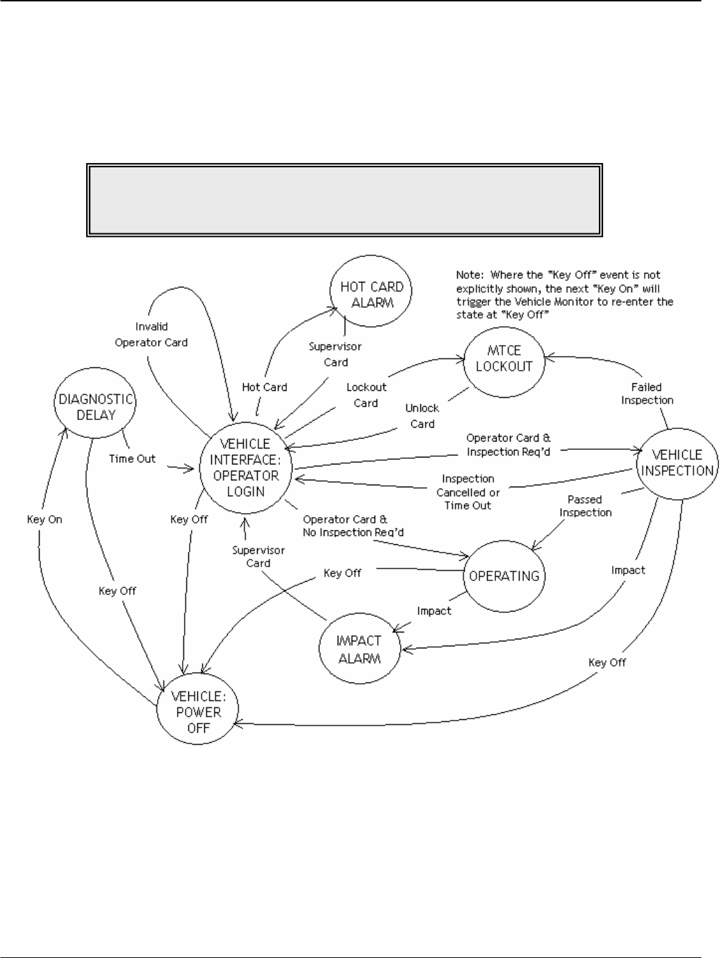
DRAFT G FORCE PLUS RF Instruction Manual
Doc #RF1 Rev.9 59 Apr/08
SYSTEM DATA
The diagram below is a type of flowchart that shows where system data is collected. A Vehicle is always in one
vehicle state (or mode of operation) and changes to a different state when an Event occurs. For example, when an
Operator fails a vehicle inspection (the Event), the Vehicle state changes from Vehicle Inspection (state #1) to
Maintenance Lockout (state #2). A Vehicle Monitor collects information about the Event (in this case, about the
Failed Inspection) and transmits it to the Fleet Manager Software via RF communications.
EVENTS
The following information is collected about each Event:
Login Operator, date/time of login, duration of login
Passed Inspection Operator, date/time of completion, passed items
Failed Inspection Operator, date/time of failure, passed items, failed item
Impact Operator, date/time of Impact, Impact type and threshold, Supervisor
Battery Operator, date/time of Battery Event, Battery state
NOTE!
To read the diagram,
begin at the circle at the bottom labeled “VEHICLE: POWER OFF”.
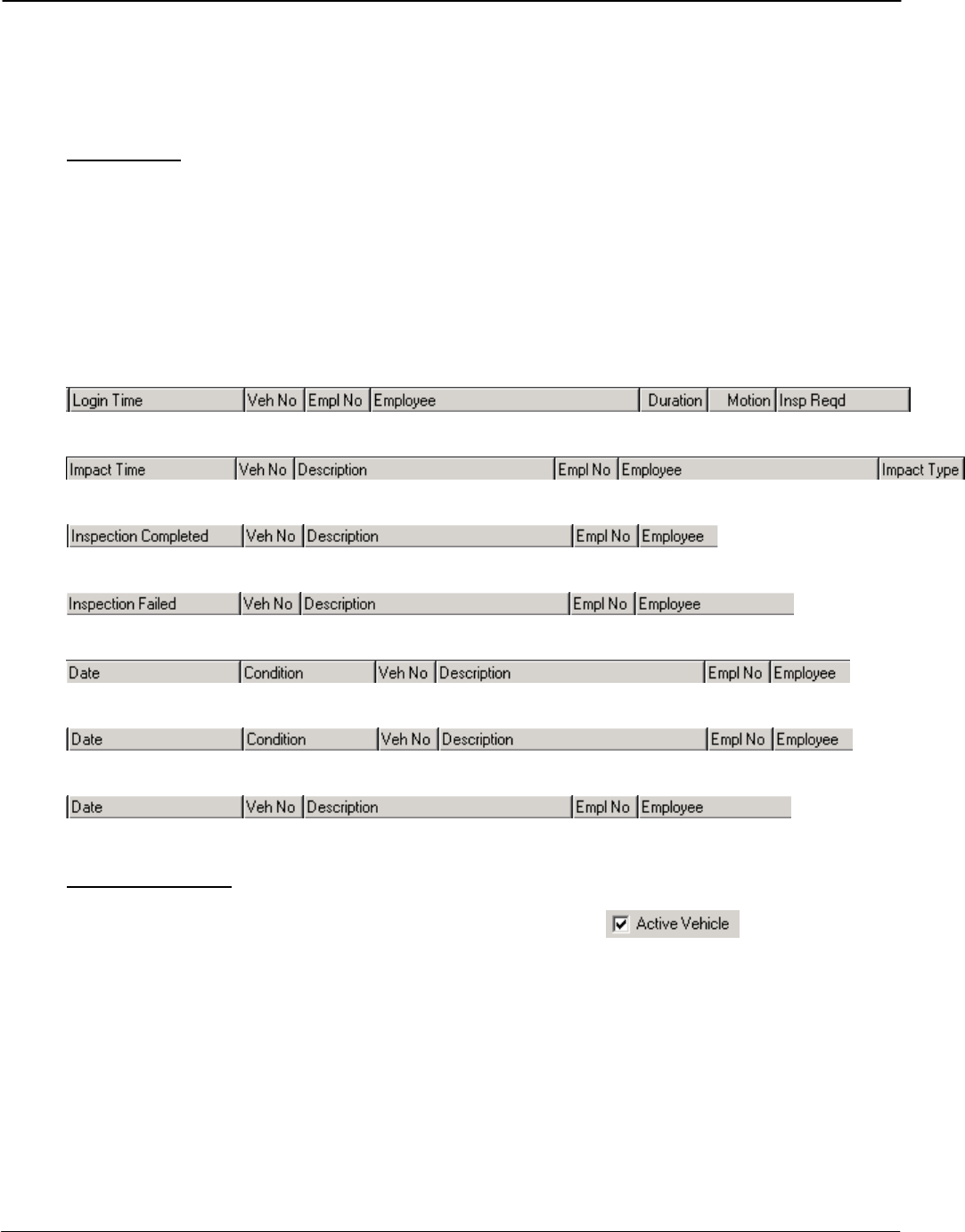
G FORCE PLUS RF Instruction Manual
Apr/08 60 Doc #RF1 Rev.9
Maintenance Employee, Maintenance Event type (Lockout or Unlock), date/time of Lockout
or Unlock
Hot Card Owner of Hot Card, date/time of Hot Card use, Supervisor
Events Tab
The Events tab is updated each time a new Event is received by the Software. Each Event is added to the
existing list of Events displayed in the Events tab lower tabs: Login, Impact, Passed Inspection, Failed
Inspection, Battery, Maintenance, Hot Card. The default order is in descending date/time order (newest
Event at the top of the tab).
Events in each tab can be resorted by clicking on the desired column heading of the title bar, depending
on the sort order desired.
Login tab:
Impact tab:
Passed Inspection tab:
Failed Inspection tab:
Battery tab:
Maintenance tab:
Hot Card tab:
Fleet Status Tab
The Fleet Status tab is a near-real time listing of all active Vehicles ( in Vehicle Settings)
in a fleet. As the Software receives each Event, the Fleet Status tab is updated to reflect the most up-to-
date information about each Vehicle in the fleet.
COLLECT DATA FROM A VEHICLE MANUALLY
In the event of an RF communications failure, the Data Logger is used as a backup means of data collection.
1. Place the Vehicle into Maintenance Lockout.
2. Press {Enter} to start the Data Logger.
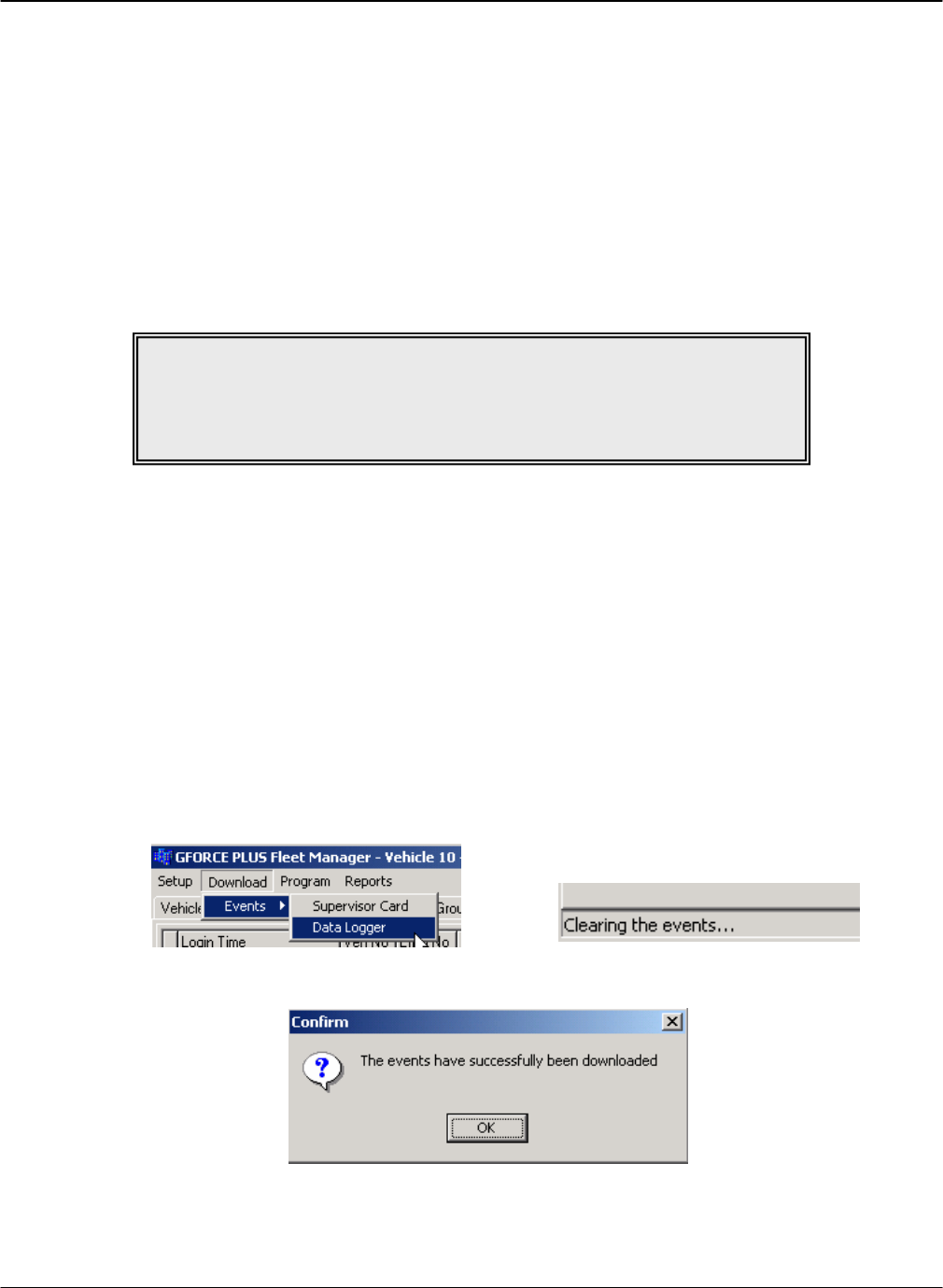
DRAFT G FORCE PLUS RF Instruction Manual
Doc #RF1 Rev.9 61 Apr/08
3. Press {4} when the Data Logger displays “Action?(1-9)”. The Data Logger will display “Action?(1-9)
Events from Veh”
4. Press {Enter} to accept the choice. The Data Logger will display “Ready for Events XXXX/1500”
5. Present the Data Logger to the Vehicle Interface.
6. Listen for a sequence of three quick beeps to indicate the interaction is complete.
7. Remove the Data Logger from the Vehicle Interface. The Vehicle Interface will display “MAINT
LOCK OUT YYYY/MM/DD HH:MM”
8. Press {Cancel} on the Data Logger. The Data Logger will display “Action?(1-9)”
9. Remove the Vehicle from Maintenance Lockout.
DOWNLOAD DATA TO THE SOFTWARE MANUALLY
1. Press {Enter} to start the Data Logger.
2. Press {1} when the Data Logger displays “Action?(1-9)”. The Data Logger will display “Action?(1-9)
Events to PC”
3. Press {Enter} to accept the choice. The Data Logger will display “Ready for PC”
4. Present the Data Logger to the Software Interface.
5. Start the Fleet Manager Software (optionally select the Events tab).
6. Select Download | Events | Data Logger from the menu. The status bar at the bottom left of the
Software will provide progress information.
7. Click the [OK] button to confirm completion.
8. Remove the Data Logger from the Software Interface. The Data Logger will display “No Events!”
9. Press {Cancel} on the Data Logger. The Data Logger will display “Action?(1-9)”
NOTE!
If the Data Logger is removed from the Vehicle Interface too soon,
six quick beeps will sound. Return the Data Logger to the Vehicle Interface
to begin data collection again. No data has been lost.

G FORCE PLUS RF Instruction Manual
Apr/08 62 Doc #RF1 Rev.9
ADD A COMMENT ABOUT AN IMPACT
A Supervisor’s comments about an Impact can be added to the Software. The comments are included on the
Impact Reports.
1. Select the Events | Impact tab.
2. Highlight (click) the Impact you want to add a Comment for.
3. Click the [Impact Comment] button to open the “Impact Comment” window.
4. Enter the comment in the Comment field to a maximum of 255 characters. The Software will not
allow entry of more than 255 characters.
5. Click the [OK] button to save the changes.
6. To edit an Impact Comment, repeat steps 2 to 5, making changes to the text as required.
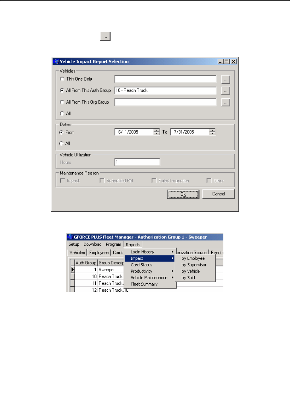
DRAFT G FORCE PLUS RF Instruction Manual
Doc #RF1 Rev.9 63 Apr/08
REPORTS
The Software provides several useful reports that can be filtered, using a “Report Selection” window, to display
ranges of data and dates. Clicking the [] button (Ellipses) opens a window that filters a report by the one
selection made.
Most reports are accessible from the Reports menu.
ORGANIZATION GROUPS
Organization Groups are optional, but if used, there is no limit to their use. Organization Groups are for
additional classification of Employees and Vehicles to provide greater report filtering (i.e. they do not limit
Operator access to Vehicles like Authorization Groups do).
The filtering selected in the “Report Selection” window below will generate an Impact Report ordered by
Employee for impacts between December 1 and December 31, 2005. It will only include impacts for
Employees belonging to the Probation Organization Group.
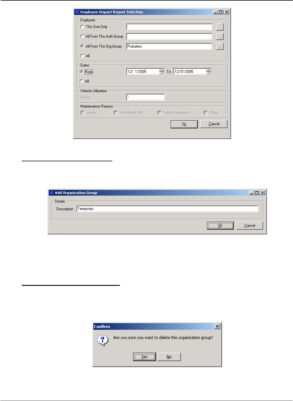
G FORCE PLUS RF Instruction Manual
Apr/08 64 Doc #RF1 Rev.9
Add an Organization Group
1. Select the Organization Groups tab.
2. Click the [Add] button to open the “Add Organization Group” window.
3. Enter an Organization Group description in the Description field.
4. Click the [OK] button to save the change. The added Group will be displayed in the Organization
Groups tab.
Delete an Organization Group
1. Select the Organization Groups tab.
2. Select the Organization Group you want to delete from the grid.
3. Click the [Delete] button to open the “Confirm” window.
4. Click the [Yes] button to confirm the deletion of the Organization Group. The deleted Group will be
removed from the Organization Groups tab.
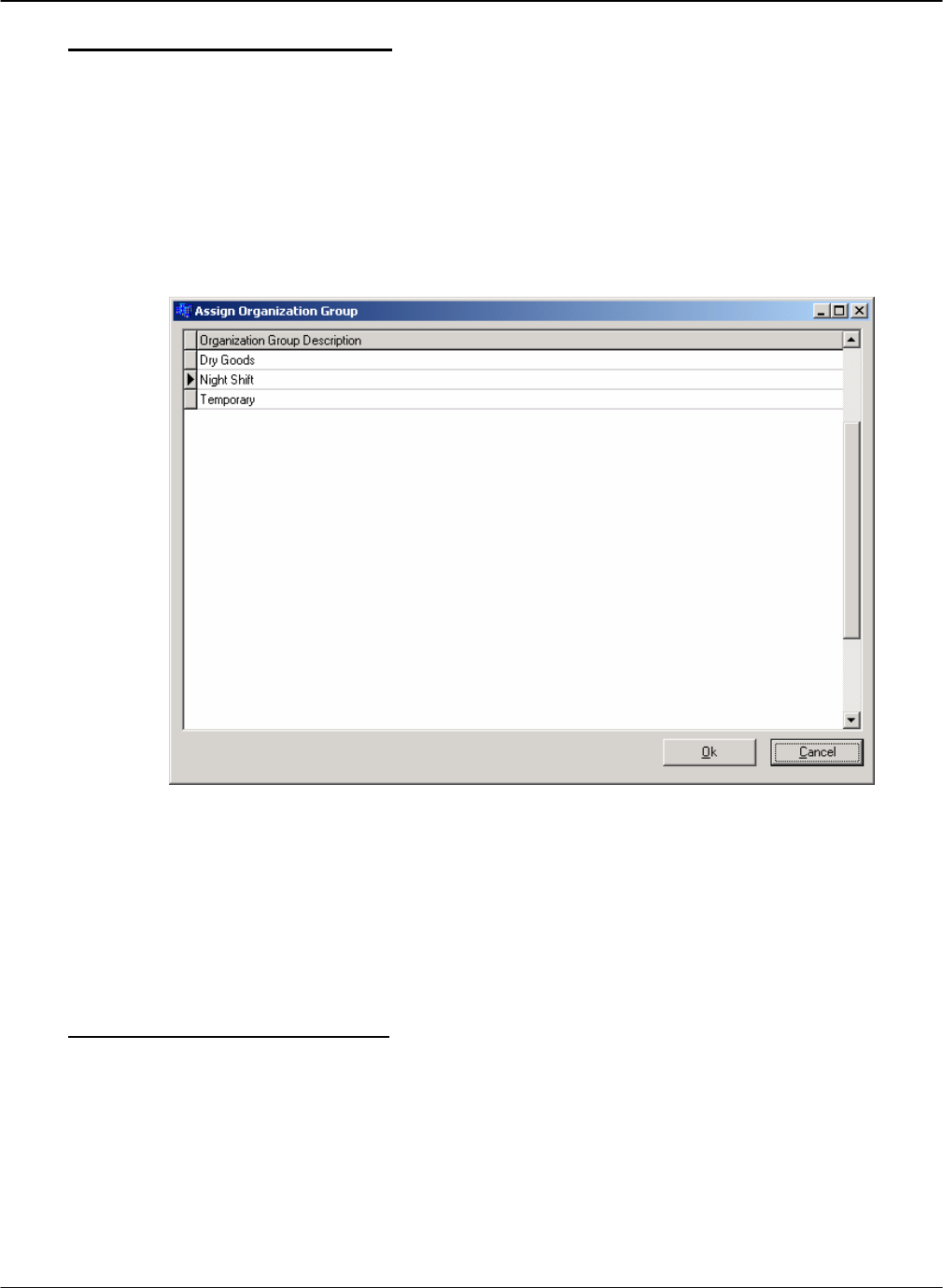
DRAFT G FORCE PLUS RF Instruction Manual
Doc #RF1 Rev.9 65 Apr/08
Assign an Organization Group
After the desired Organization Groups are created, Employees and/or Vehicles are assigned the
Organization Groups.
1. Select the Employees or Vehicles tab, as required.
2. Select the desired Employee or Vehicle from the grid.
3. Click the Assign Organization Groups tab.
4. Assign Organization Groups to the Employee or Vehicle.
a. Click the [Add] button to open the “Assign Organization Group” window.
b. Select an Organization Group from the grid.
c. Click the [OK] button to save the addition.
d. HINT: Double-click an Organization Group to save a step!
e. Repeat steps a. to d. until all Organization Groups for the Employee or Vehicle are shown in the
Assign Organization Groups tab.
5. Repeat steps 2 to 4 until all Organization Groups assignments for Employees or Vehicles are done.
Organization Group Examples
Create a Probation group to compare Impact or Productivity Reports for all Employees and for
Probation Employees
Create a Night Shift group to compare Impact or Productivity Reports for all Employees and for
Night Shift Employees
Create an Outside group to compare Impact or Productivity Reports for all Vehicles and for Outside
Vehicles
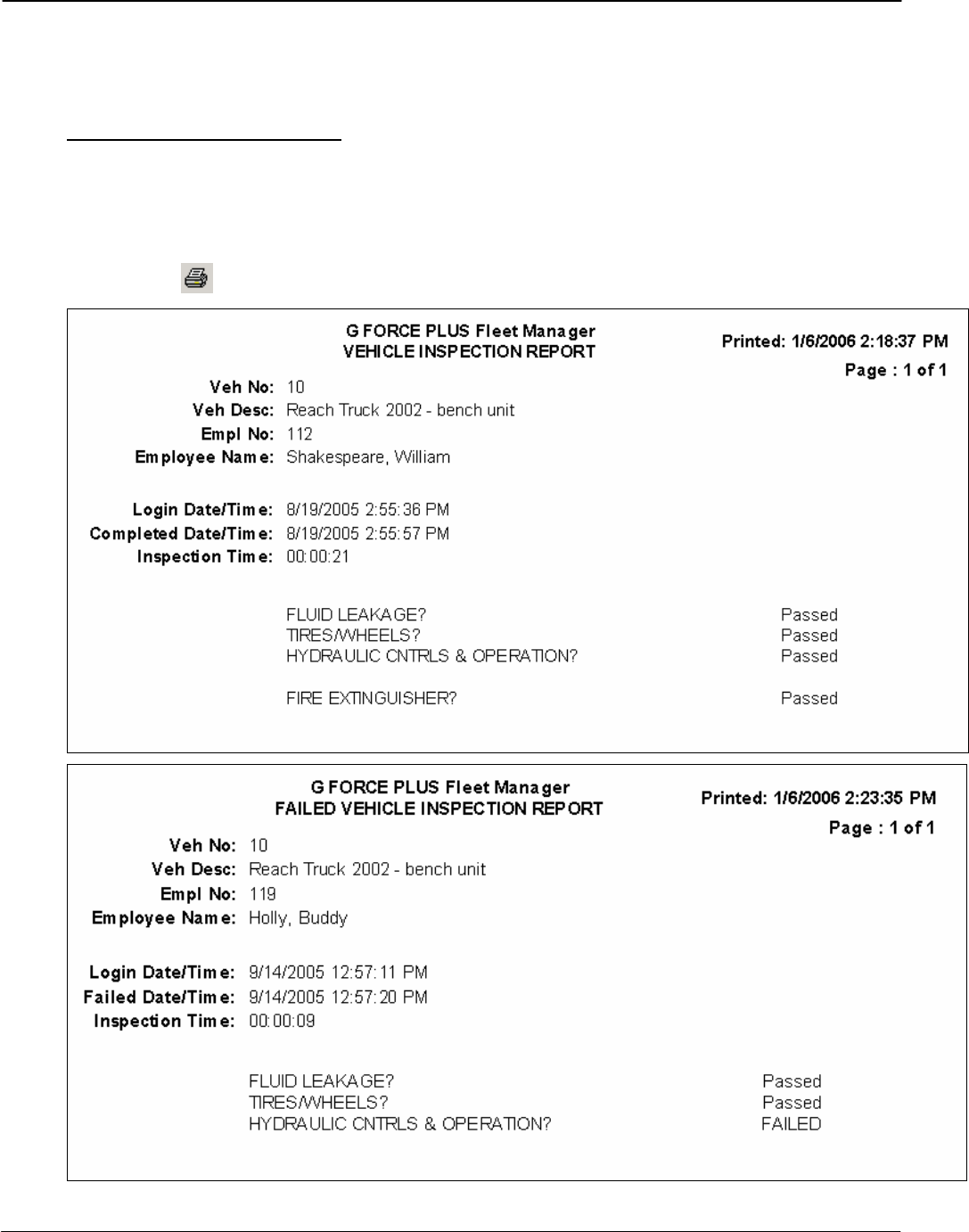
G FORCE PLUS RF Instruction Manual
Apr/08 66 Doc #RF1 Rev.9
SAMPLE REPORTS
The following reports are available in the Software:
Vehicle Inspection Reports
1. Select the Events tab.
2. Select the Passed Inspection or Failed Inspection tab at the bottom of the Events tab.
3. Double-click the desired Inspection Event to generate the report in a “Print Preview” window.
4. Click the [] button (Print) to print the report or click [Close].
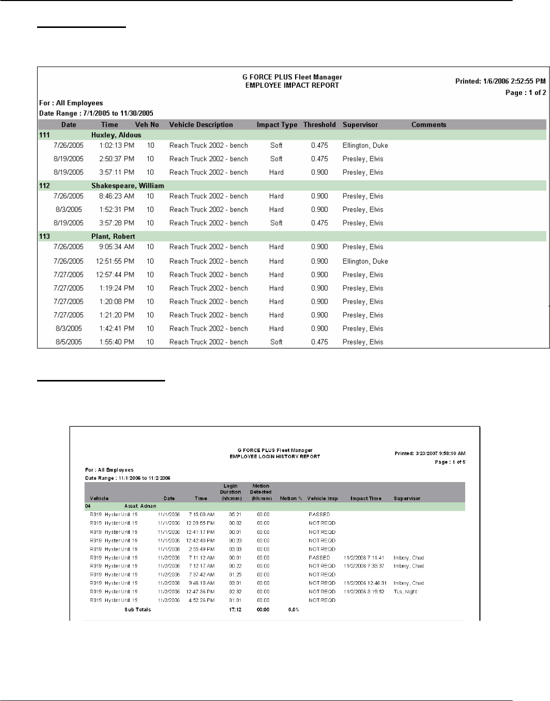
DRAFT G FORCE PLUS RF Instruction Manual
Doc #RF1 Rev.9 67 Apr/08
Impact Reports
There are four Impact Reports to choose from, ordered by Employee, Vehicle, Supervisor or Shift.
Login History Reports
There are two Login History Reports to choose from, ordered by Employee or Vehicle. The reports
include both Login and Impact details.
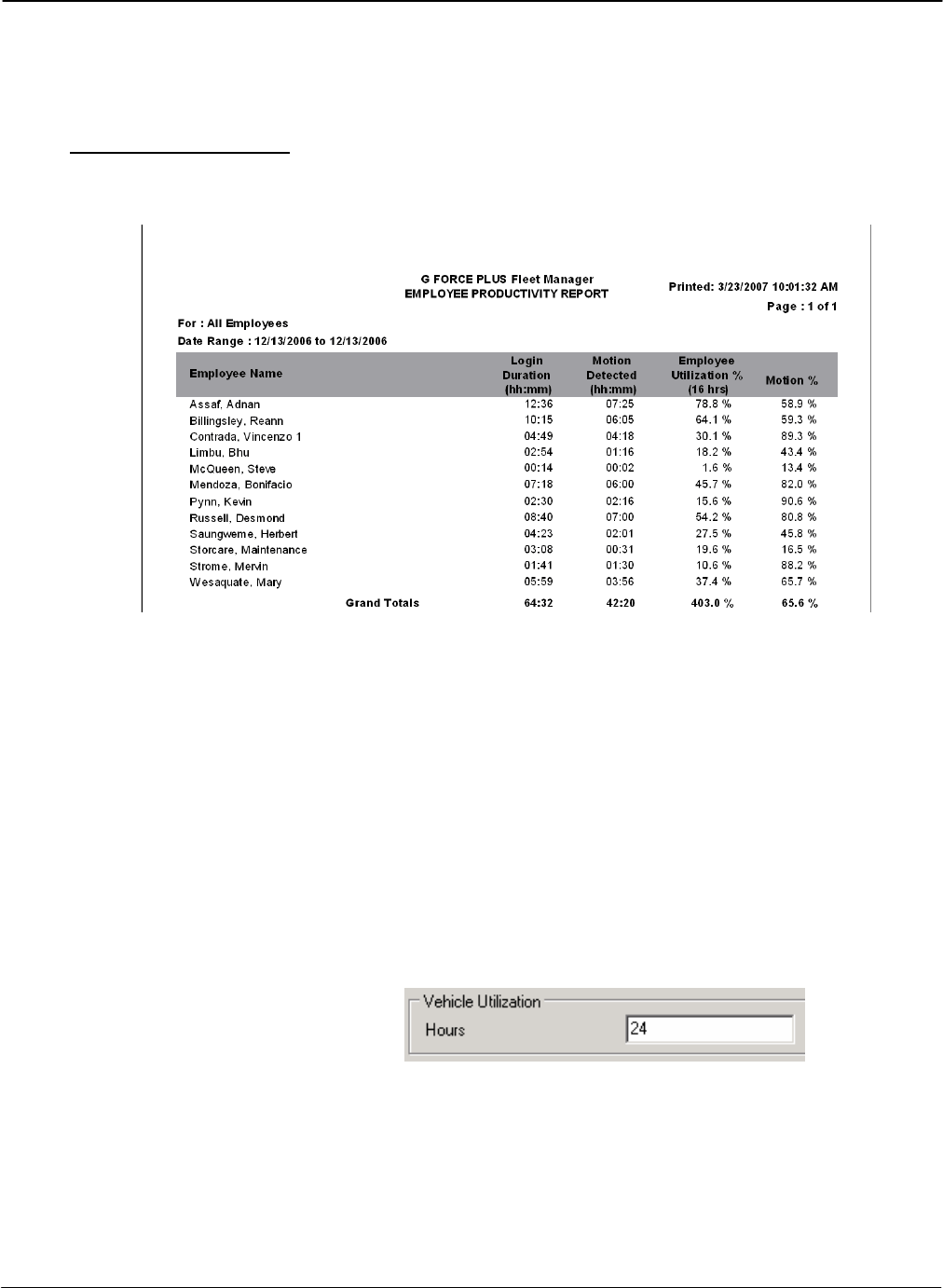
G FORCE PLUS RF Instruction Manual
Apr/08 68 Doc #RF1 Rev.9
Productivity Reports
There are two Productivity Reports to choose from, ordered by Employee or Vehicle. The reports include
totals only of Login data for each Employee or Vehicle.
An explanation of Productivity Report columns:
Login Duration The total login time (by Vehicle or Employee depending on the
chosen report) within the selected date range
Motion Detected The total motion time (by Vehicle or Employee depending on the
chosen report) as determined by the Vehicle Monitor white wire
input within the selected date range
Vehicle/Employee Utilization % Login Duration as a percentage of available hours as entered in
the “Report Selection” window. (Vehicle/Employee Utilization)
Hours entered should be the total number of hours the resource is
available for use (for example, enter 8 hours for a single shift or
24 hours for a single day of three shifts or 112 hours for a full
week of two shifts or 168 hours for a full week of three shifts,
etc.)
Motion % Motion Detected as a percentage of Login Duration.
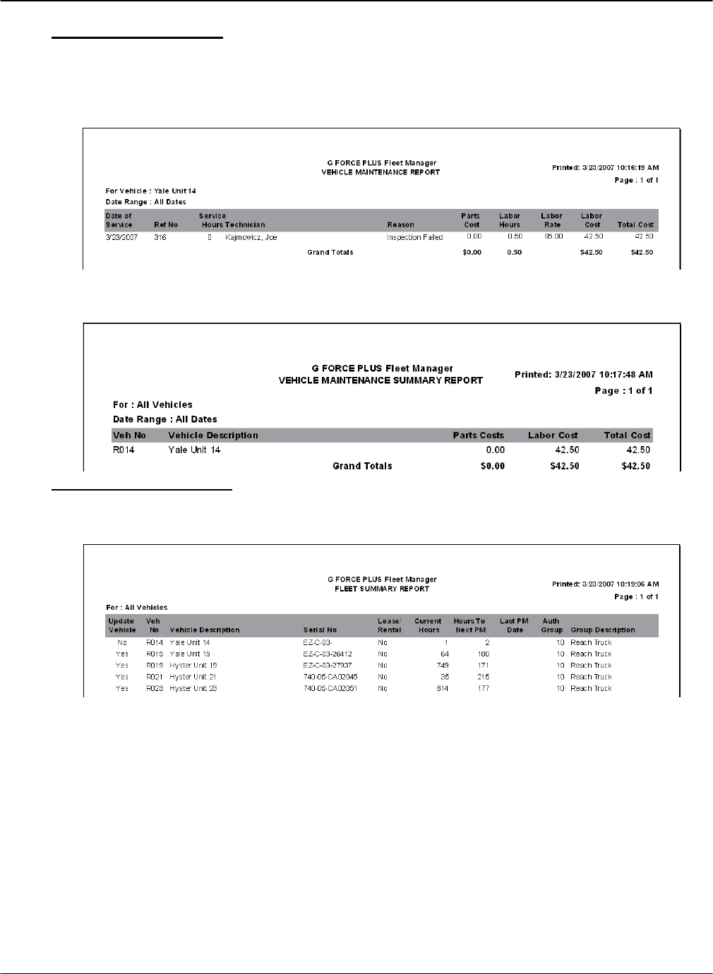
DRAFT G FORCE PLUS RF Instruction Manual
Doc #RF1 Rev.9 69 Apr/08
Maintenance Reports
There are three Maintenance reports to choose from. The Technician Maintenance and Vehicle
Maintenance Reports include Work Order details for one selected Technician or Vehicle over a selected
date range.
The Vehicle Maintenance Summary includes a total only of Work Orders for selected Vehicles over a
selected date range.
Fleet Summary Report
The Fleet Summary Report is a summary listing of selected Vehicles.
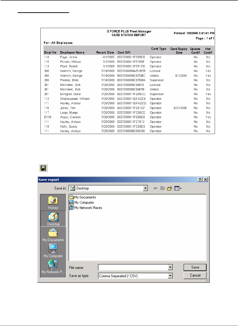
G FORCE PLUS RF Instruction Manual
Apr/08 70 Doc #RF1 Rev.9
Card Status Report
The Card Status Report is a summary listing of all Cards in ascending Recertification Date order.
EXPORTING REPORT DATA
Any report data can be exported to a .CSV file for use outside the Software (i.e. in Microsoft® Excel).
1. Generate the desired report in the “Print Preview” window.
2. Click the [] button (Save Report) to open the “Save report” window.
3. Select the desired file destination from the Save in: field.
4. Enter a meaningful file name in the File name: field.
5. Select “Comma Separated (*.CSV)” from the Save as type: field.
6. Click the [Save] button to save the file to the chosen location.
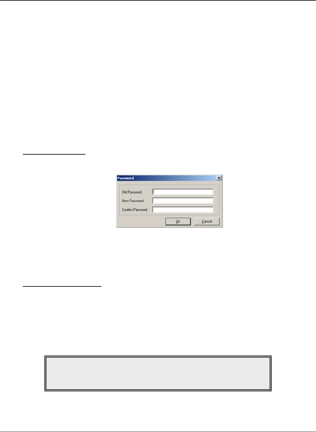
DRAFT G FORCE PLUS RF Instruction Manual
Doc #RF1 Rev.9 71 Apr/08
ADDITIONAL SYSTEM FEATURES
PASSWORD
While a password is not required, it is recommended to prevent unauthorized access to the Fleet Manager
data. Password rules are as follows:
Case-sensitive, meaning “goldfish”, “Goldfish”, and “GOLDFISH” are three different passwords
Must be at least 6 characters long, and no more than 14 characters long
Allowable characters can be from the full keyboard set, including upper and lower case A-Z, 0-9, and
special characters such as: !@#$%^&*()_+{}<>?
A space is also a valid character but cannot be the first or last position
It is best to mix letters, numbers and characters
Avoid easily cracked passwords like your name, telephone number, pet’s name, etc.
Set the Password
1. Select Setup | Password… from the menu.
2. Type the desired password in the New Password field (leave the Old Password field blank).
3. Retype the desired password in the Confirm Password field.
4. Click the [OK] button to save the change.
Change the Password
1. Select Setup | Password… from the menu.
2. Type the old password in the Old Password field.
3. Type the new password in the New Password field.
4. Retype the new password in the Confirm Password field.
5. Click the [OK] button to save the change.
NOTE!
To remove the password, follow the step to change the password and leave
the New Password and Confirm Password fields blank.
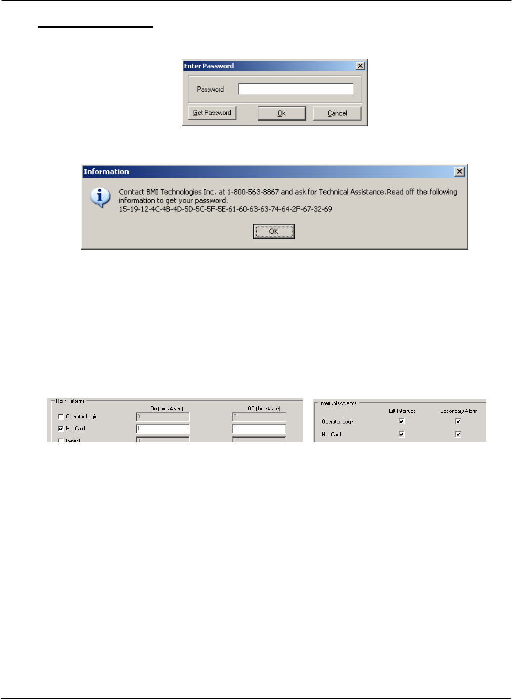
G FORCE PLUS RF Instruction Manual
Apr/08 72 Doc #RF1 Rev.9
Lost the Password?
1. Click the [Get Password] button on the “Enter Password” window.
2. Contact Technical Assistance at BMI Technologies Inc. at 1-800-563-8867 and provide the code from
the “Information” window to retrieve your password.
HOT CARDS
Hot Cards are Cards that have been identified as being on the Hot Card List. A Card can be placed on the Hot
Card List to prevent its use in the system. For example, a lost or stolen card should be placed on the Hot Card
List.
Each Vehicle Monitor stores the Hot Card List, and when a Hot Card is used, the Vehicle enters Hot Card
state. The System Settings and the Authorization Group settings of the Vehicle determine the Vehicle’s
behavior in Hot Card state.
The Hot Card List can include up to 30 Cards and is maintained in the Fleet Manager Software. Each time
there is a change to the Hot Card List, it is automatically updated on all Vehicle Monitors via RF
communications. The Hot Card List includes all Cards that are flagged as “Yes” in the Hot Card column of
the Cards tab.
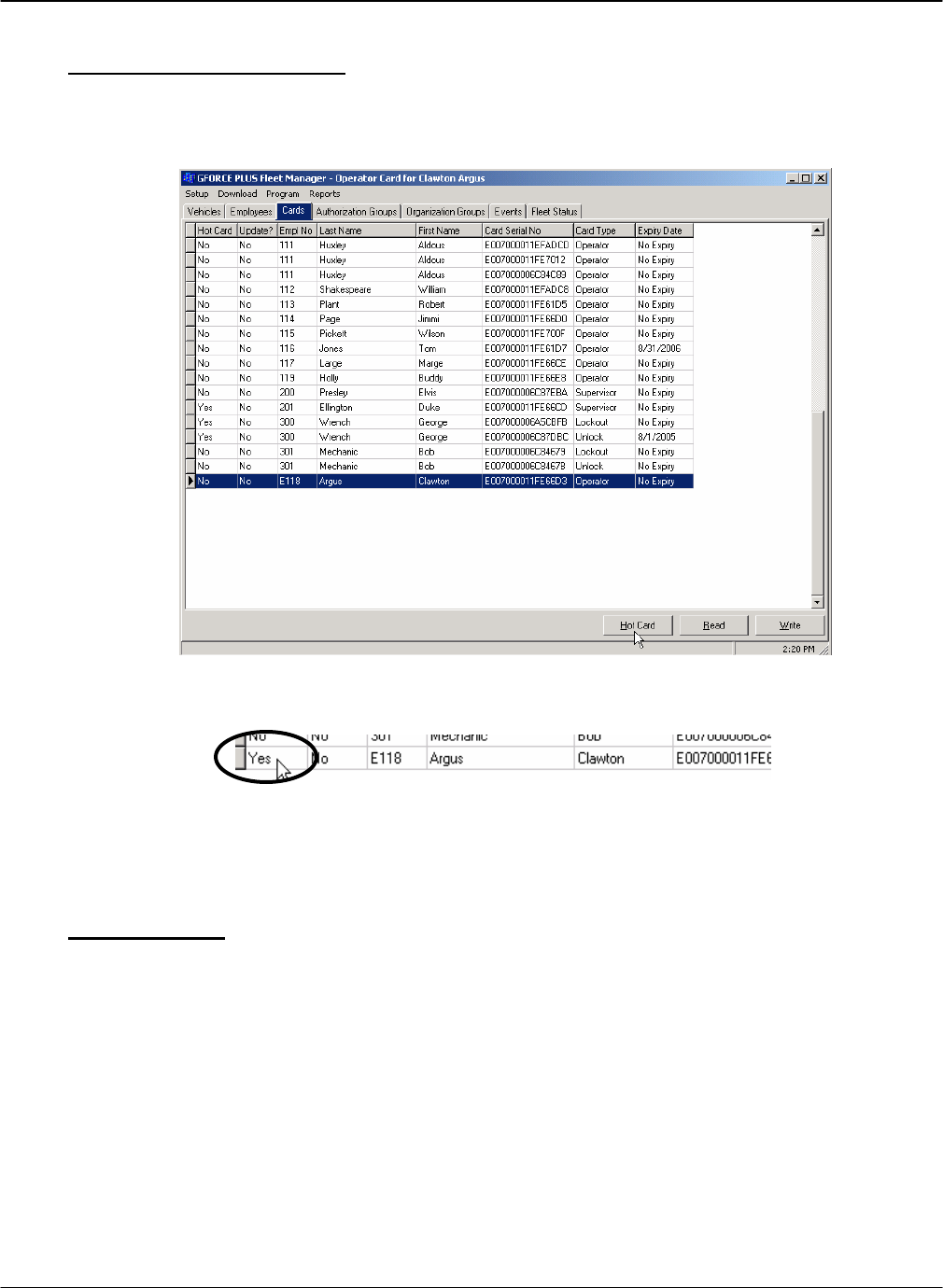
DRAFT G FORCE PLUS RF Instruction Manual
Doc #RF1 Rev.9 73 Apr/08
Maintain the Hot Card List
1. Select the Cards tab.
2. Select the Card to add to the Hot Card List.
3. Click the [Hot Card] button at the bottom of the tab. The field indicating if the Card is a Hot Card
will change from No to Yes.
4. The RF communications will update the Hot Card list on each Vehicle.
OTHER DATA LOGGER FUNCTIONS
Clear Data (#9)
This function is used to clear data from the Data Logger. This includes Vehicle ID and settings slots 1 to
9, and Events in memory.
1. Press {Enter} to start the Data Logger.
2. Press {9} when the Data Logger displays “Action?(1-9)”. The Data Logger will display “Action?(1-
9) Clear Data”
3. Press {Enter} to accept the choice. The Data Logger will display “Select Type:”
4. Select the desired type of data to clear.
a. Press {1} for Vehicle ID slots. The Data Logger will display “Clear IDs? Enter to Proceed”, or
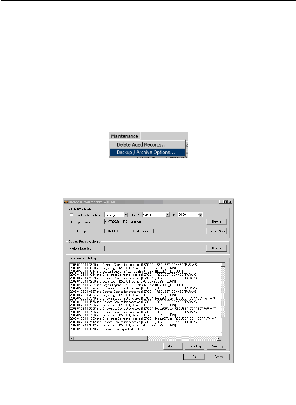
G FORCE PLUS RF Instruction Manual
Apr/08 74 Doc #RF1 Rev.9
b. Press {2} for Vehicle setting slots. The Data Logger will display “Clear Settings? Enter to
Proceed”, or
c. Press {3} for Events. The Data Logger will display “Clear Events? Enter to Proceed”
5. Press {Enter} to confirm the selection. The Data Logger will display “Clearing…”, followed by
“Memory Cleared”, followed by “Select Type:”
6. Repeat steps 4 and 5 as required.
7. Press {Cancel} when done. The Data Logger will display “Action?(1-9)”.
Database Maintenance
Setting up Backup
1. Click on Maintenance | Backup/Archive Options
2. This screen will appear. Automatic backups may be scheduled daily, weekly, or monthly and
the location the data is backed up to can be changed. Schedules may be daily, weekly, or
monthly.
3. To perform a backup on command, simply click the Backup Now button, then Ok. The
backup filename will be the date it was performed (2008-04-01.bkp for example).
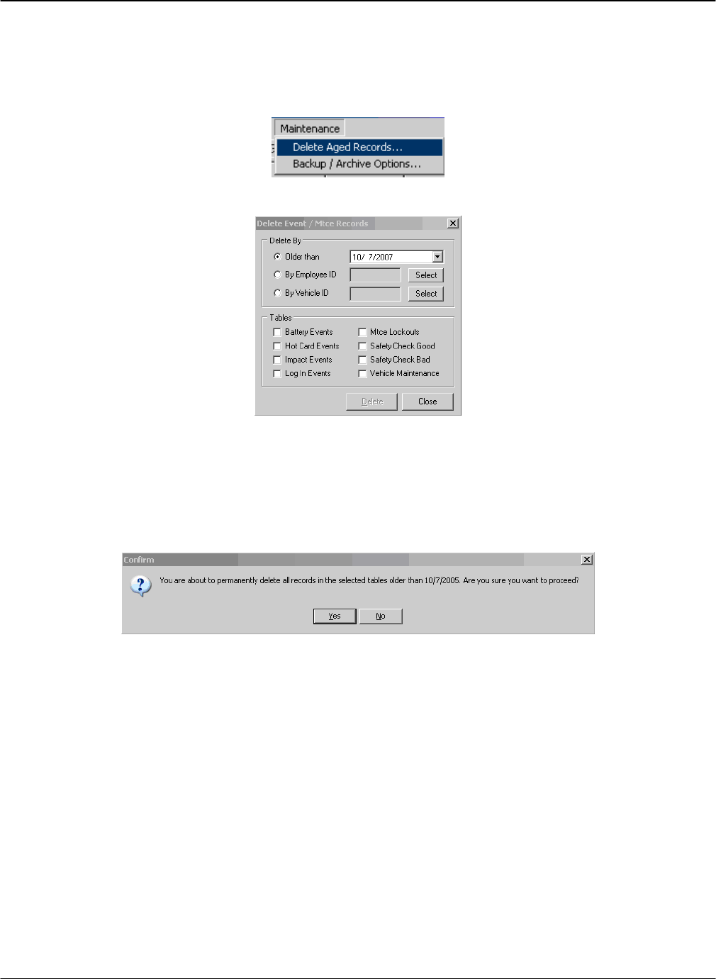
DRAFT G FORCE PLUS RF Instruction Manual
Doc #RF1 Rev.9 75 Apr/08
Deleting Aged Records
1. Click Maintenance | Delete Aged Records.
2. This window will appear:
3. Choose which items you wish to remove by date, employee ID, or vehicle ID.
4. Choose the event types you want removed.
5. Click Delete, and this window will appear. Click Yes to have the items permanently
removed from the database. Click No to cancel the operation.
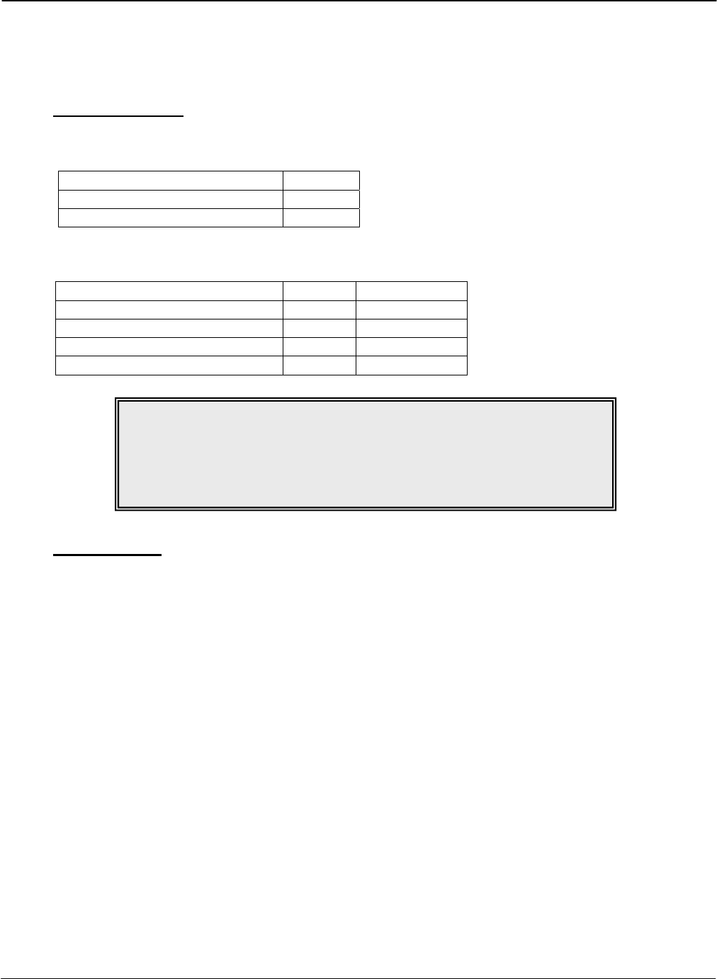
G FORCE PLUS RF Instruction Manual
Apr/08 76 Doc #RF1 Rev.9
REFERENCE
RECOMMENDED SETTINGS
Battery Settings
The recommended situation-specific Battery Fault settings are:
Setting General
High Fault Threshold (SGP) 1650
Low Fault Threshold (SGP) 780
The recommended situation-specific Battery Charge settings are:
Setting General Freezer Only
OK To Charge Threshold (SGP) 1200 1200
OK To Charge Timer (minutes) 45 45
Must Charge Threshold (SGP) 1150 1160
Must Charge Timer (minutes) 40 40
Impact Types
A Hard Impact occurs when a Vehicle hits an immovable object such as a post or a Vehicle of the same or
larger size. The Vehicle generally stops on impact and its energy is dissipated instantly. The energy from
this type of impact is high in amplitude and short in duration (10 ms).
A Soft Impact occurs when a Vehicle hits an object like product or racking. The Vehicle generally comes
to a stop some distance after the impact, as it takes some time for its energy to dissipate. The energy from
this type of impact is low in amplitude and long in duration (300 ms). This type of impact tends to be
most damaging and most often causes an Impact alarm.
NOTE!
For help adjusting Battery settings
to reflect your company’s charging policy,
contact Technical Assistance at
BMI Technologies Inc. at 1-800-563-8867.

DRAFT G FORCE PLUS RF Instruction Manual
Doc #RF1 Rev.9 77 Apr/08
DATA FIELD DEFINITIONS
This section explains the settings that must be established in the Software. It is divided by major category:
System Settings, Authorization Groups, Vehicles, and Employees. Settings are listed in the order they appear
in the Software.
System Settings
System Settings apply to all Vehicles in a fleet, and changes require all Vehicles to be reprogrammed with
the Data Logger.
Card Expiration Warning (days) The Vehicle Interface displays “CARD EXPIRY SOON” with
the “LOGIN APPROVED” message when a Card’s Expiry
Date or (enforced) Recertification Date is within this period of
time.
Vehicle Inspection Frequency Choose one of five options for Vehicle Inspections:
1) Every Login
2) Every Operator Change
3) First Login Per Operator Per Interval (i.e. shift)
4) First Login Per Interval (i.e. shift)
5) No Vehicle Inspection
Vehicle Inspection Interval (hours) When items 3) or 4) are selected for the Vehicle Inspection
Frequency, enter the shift length (i.e. 8, 12, or 24 hours).
Vehicle Inspection Inactivity Timer
(seconds) The Vehicle reverts to Operator Login (Vehicle Interface
displays “OPERATOR LOGIN PRESENT CARD”) when
there is no key-press within this period of time during the
Vehicle Inspection.
Preventative Maintenance Due
Warning (hours) The Vehicle Interface displays “PM DUE SOON” when a
Vehicle’s scheduled Preventative Maintenance is within this
period of time. After the Preventative Maintenance is due, the
Vehicle Interface displays “PM DUE NOW”.
PM Automatic Maintenance Lockout
on Past Due (if checked) The Vehicle enters Maintenance Lockout (Vehicle Interface
displays “MAINTENANCE LOCKOUT”) at the next key-on
after scheduled Preventative Maintenance is due.
Horn Patterns (On/Off) Set unique horn patterns for each Vehicle state. An unchecked
field indicates no horn will sound for the state. A value of 1 = ¼
second, therefore when On=2 and Off=1200, the horn sounds for
½ second every 5 minutes in that state.
Battery High Fault Threshold (SGP) The Vehicle enters Battery Fault when a battery has a sustained
level above this specific gravity point threshold. The Vehicle
Interface displays “BATTERY FAULT OVER/UNDER
VOLT.” and the red Battery Fault LED illuminates. Other
interrupts and alarms will exhibit as programmed. To begin
clearing this condition, the Vehicle must be placed into
Maintenance Lockout. See “RECOMMENDED SETTINGS”.

G FORCE PLUS RF Instruction Manual
Apr/08 78 Doc #RF1 Rev.9
Battery Low Fault Threshold (SGP) The Vehicle enters Battery Fault when a battery has a sustained
level below this specific gravity point threshold. The Vehicle
Interface displays “BATTERY FAULT OVER/UNDER
VOLT.” and the red Battery Fault LED illuminates. Other
interrupts and alarms will exhibit as programmed. To begin
clearing this condition, the Vehicle must be placed into
Maintenance Lockout. See “RECOMMENDED SETTINGS”.
Authorization Groups
Authorization Group settings apply to all Vehicles in an Authorization Group, and changes require all
Vehicles in the Authorization Group to be reprogrammed with the Data Logger.
General Tab
Auth Group Enter a unique Authorization Group from 1 to 64.
Description Enter an Authorization Group description.
Diagnostic Delay (seconds) For the defined number of seconds, all electrical circuits are
closed so a Vehicle can conduct its internal diagnostics
without error. The Vehicle Interface displays “VEH
SYSTEM CHECK PLS WAIT..” after key-on.
Preventative Maintenance Time
Tracking Method Select one of two options to track time for scheduled
Preventative Maintenance purposes:
1) Login Time
2) Motion Time
Preventative Maintenance
Interval/Frequency every (hours) This value is used to increment the current G FORCE Hour
Meter to determine when the next scheduled Preventative
Maintenance should be.
Impact Automatic Reset (if checked) When this field is checked, the Vehicle Interface displays
“OPERATOR LOGIN PRESENT CARD” after an Impact
has been detected.
Battery Monitoring (if checked) When this field is checked, the Vehicle battery is monitored.
Additional settings are required for customization.
Settings Tab
Operator Login Lift Interrupt (if
checked) The circuit wired to interrupt the Vehicle lift opens during
Operator Login (lift interrupt created).
Operator Login Secondary Alarm (if
checked) The circuit wired to create a secondary alarm opens during
Operator Login.
Hot Card Lift Interrupt (if checked) The circuit wired to interrupt the Vehicle lift opens when a
Hot Card is detected for Operator Login (lift interrupt
created).
Hot Card Secondary Alarm (if
checked) The circuit wired to create a secondary alarm opens when a
Hot Card state is detected for Operator Login).
Maintenance Lockout Lift Interrupt
(if checked) The circuit wired to interrupt the Vehicle lift opens when a
Vehicle enters Maintenance Lockout (lift interrupt created).

DRAFT G FORCE PLUS RF Instruction Manual
Doc #RF1 Rev.9 79 Apr/08
Maintenance Lockout Secondary
Alarm (if checked) The circuit wired to create a secondary alarm opens when a
Vehicle enters Maintenance Lockout.
Impact Lift Interrupt (if checked) The circuit wired to interrupt the Vehicle lift opens when an
Impact is detected (lift interrupt created)
Impact Secondary Alarm (if checked) The circuit wired to create a secondary alarm opens when an
Impact is detected.
Impact Delay (seconds) There is a delay for the defined number of seconds before the
Lift Interrupt and Secondary Alarm circuits open after an
Impact is detected.
Battery OK To Charge Threshold
(SGP) The Vehicle enters OK To Charge when a battery discharges
to a level below this specific gravity point threshold for a
sustained period of time (see Battery OK To Charge Timer
below). The Vehicle Interface displays “BATTERY OK TO
CHARGE” and the Battery Charge LED illuminates as
amber. Other alarms will exhibit as programmed.
Set the upper limit of the OK To Charge battery range in
specific gravity points according to your company’s battery
charging policy. See “RECOMMENDED SETTINGS”.
Battery OK To Charge Timer
(minutes) The Vehicle enters OK To Charge when a battery discharges
to a level below the Battery OK To Charge Threshold for this
period of time. The Vehicle Interface displays “BATTERY
OK TO CHARGE” and the Battery Charge LED illuminates
as amber. Other alarms will exhibit as programmed.
Set this value to reflect your company’s battery charging
policy. See “RECOMMENDED SETTINGS”.
Battery Must Charge Threshold
(SGP) The Vehicle enters Must Charge when a battery discharges to
a level below this specific gravity point threshold for a
sustained period of time (see Battery Must Charge Timer
below). The Vehicle Interface displays “BATTERY MUST
CHARGE!” and the Battery Charge LED flashes red. Other
interrupts and alarms will exhibit as programmed.
Set the upper limit of the Must Charge battery range in
specific gravity points according to your company’s battery
charging policy. See “RECOMMENDED SETTINGS”.
Battery Must Charge Timer (minutes) The Vehicle enters Must Charge when a battery discharges to
a level below the Battery Must Charge Threshold for this
period of time. The Vehicle Interface displays “BATTERY
MUST CHARGE!” and the Battery Charge LED flashes red.
Other interrupts and alarms will exhibit as programmed.
Set this value to reflect your company’s battery charging
policy. See “RECOMMENDED SETTINGS”.
Battery Must Charge Lift Interrupt (if
checked) The circuit wired to interrupt the Vehicle lift opens when
Battery Must Charge is detected (lift interrupt created).
Battery Must Charge Secondary
Alarm (if checked) The circuit wired to create a secondary alarm opens when
Battery Must Charge is detected.

G FORCE PLUS RF Instruction Manual
Apr/08 80 Doc #RF1 Rev.9
Battery Must Charge Delay (minutes) There is a delay for the defined number of minutes before the
Lift Interrupt and Secondary Alarm circuits open after Battery
Must Charge is detected.
Battery Fault Lift Interrupt (if
checked) The circuit wired to interrupt the Vehicle lift opens when
Battery Fault is detected (lift interrupt created).
Battery Fault Secondary Alarm (if
checked) The circuit wired to create a secondary alarm opens when
Battery Fault is detected.
Battery Fault Delay (minutes) There is a delay for the defined number of minutes before the
Lift Interrupt and Secondary Alarm circuits open after Battery
Fault is detected.
Vehicle Defaults Tab RECOMMENDED BUT NOT MANDATORY
Battery Nominal Voltage Set the default nominal battery voltage for Vehicles in this
Authorization Group. Editable in Vehicle settings.
Impact Hard Threshold (G) Set the default upper limit for Vehicles in the Authorization
Group for determination of hard Impacts. Editable in Vehicle
settings.
Impact Hard Samples Set the default number of samples for Vehicles in the
Authorization Group for determination of hard Impacts.
Editable in Vehicle settings.
Impact Soft Threshold (G) Set the default upper limit for Vehicles in the Authorization
Group for determination of soft Impacts. Editable in Vehicle
settings.
Impact Soft Samples Set the default number of samples for Vehicles in the
Authorization Group for determination of soft Impacts.
Editable in Vehicle settings.
Vehicles
The Vehicle settings are specific to a Vehicle, and changes require the Vehicle to be reprogrammed with
the Data Logger.
Gray fields are read-only; they cannot be edited.
General Tab
Vehicle ID A system-assigned vehicle identifier for reference only.
Vehicle No Enter the company-assigned vehicle identifier (i.e. Unit No).
Serial No Enter the OEM serial number.
Description Enter the Vehicle description (i.e. make, model, year
purchased).
Authorization Group Click the [Link To…] button to select the Authorization
Group the Vehicle belongs to.
Authorization Desc. Description of the Authorization Group the Vehicle belongs
to.
Rental (if checked) Indicates the Vehicle is a rental. For reference only.

DRAFT G FORCE PLUS RF Instruction Manual
Doc #RF1 Rev.9 81 Apr/08
Comment Comment field for reference only (i.e. year of purchase).
Settings Tab
Impact Hard Threshold (G) Threshold for hard impact detection for the vehicle (hard
impacts have greater intensity and shorter duration). See
“RECOMMENDED SETTINGS”.
Impact Hard Samples Number of samples measured for hard impact detection for the
vehicle. See “RECOMMENDED SETTINGS”.
Impact Soft Threshold (G) Threshold for soft impact detection for the vehicle (soft
impacts have lesser intensity and longer duration). See
“RECOMMENDED SETTINGS”.
Impact Soft Samples Number of samples measured for soft impact detection for the
vehicle. See “RECOMMENDED SETTINGS”.
(Impact) Lift Interrupt From Authorization Group settings. Yes for Lift Interrupt
when Impact is detected. No for no Lift Interrupt when
Impact is detected.
(Impact) Secondary Alarm From Authorization Group settings. Yes for Secondary Alarm
when Impact is detected. No for no Secondary Alarm when
Impact is detected.
(Impact) Interrupt/Alarm Delay
(seconds) From Authorization Group settings. Number of seconds
before Lift Interrupt or Secondary Alarm engages when
Impact is detected.
(Impact) Automatic Reset From Authorization Group settings. Yes if Automatic Reset
occurs when Impact is detected.
Hour Meter at Installation Vehicle hour meter reading when Vehicle equipped with a G
FORCE PLUS/RF Vehicle Monitor is put into service.
G FORCE Hour Meter G FORCE PLUS/RF Vehicle Monitor Hour Meter reading
determined by PM Time Tracking Method.
Actual Vehicle Hours Addition of values from Hour Meter at Installation and G
FORCE Hour Meter.
Date of Last PM The most recent date of a Maintenance Work Order identified
with a Scheduled PM reason. If no Maintenance Work Orders
are entered, this field will remain blank.
Next PM Due in (hours) Number of hours that the next scheduled PM is due for the
Vehicle.
PM Time Tracking Method From Authorization Group settings. Method of tracking time
for scheduled Preventative Maintenance purposes: Login or
Motion.
PM Interval/Frequency every (hours) From Authorization Group settings. Value used to update
when the next scheduled Preventative Maintenance should be.
Battery Nominal Voltage Nominal battery voltage for the Vehicle.
OK To Charge Threshold Upper limit of the OK To Charge battery range in specific
gravity points.
Must Charge Threshold Upper limit of the Must Charge battery range in specific
G FORCE PLUS RF Instruction Manual
Apr/08 82 Doc #RF1 Rev.9
gravity points.
Employees
Employee No Enter the Employee’s unique company-assigned identifier.
Active Employee (if checked) The Employee will be included on reports.
First Name Enter the Employee’s first name.
Last Name Enter the Employee’s last name.
Enforce Recertification Date (if
checked) The Employee will be denied access to a Vehicle if the
Recertification Date is past due.
Recertification Date Enter the date an Employee’s Vehicle operation and safety
training expires.
Update Card (if checked) Read-only field. The Employee’s Operator Card is outdated.
Position Select Employee’s Position from the drop-down list. The
Position does not limit the Card Type that can be assigned.
Comment Comment field for reference only.
TROUBLESHOOTING
BACKING UP THE DATABASE
Care should be taken to protect the Fleet Manager data from hard drive failure by establishing a regular
backup routine. The backup can be accessed through Maintenance | Backup/Archive Options.
Contact your organization’s computer technician for assistance with this task.
NOTE!
For customized help with your particular installation, contact
Technical Assistance at BMI Technologies Inc. at 1-800-563-8867.

DRAFT G FORCE PLUS RF Instruction Manual
Doc #RF1 Rev.9 83 Apr/08
SOFTWARE LICENCE
G FORCE PLUS Fleet Manager Software (herein after called the “Software”), as a component of the G
FORCE PLUS and G FORCE PLUS RF Powered Industrial Vehicle Fleet Management Systems, is
developed, maintained and owned by BMI Technologies Inc.
The purchase of only one (1) copy of the Software entitles the purchaser (herein after called the “User”) to
load the Software on as many computers as desired for one single physical address.
The Software is certified for use on PCs running Microsoft® Windows XP Professional.
All rights of any kind, which are not expressly granted, are entirely and exclusively reserved to and by BMI
Technologies Inc. The User may not rent, lease, modify, translate, reverse engineer, decompile, disassemble,
or create derivative works based on the Software, nor permit anyone else to do so. The User shall not allow
access to the Software nor make available to others a connection with a service bureau, application service
provider, or similar business, nor permit anyone else to do so.