BMI Technologies VUI00 Vehicle User Interface RFID Reader User Manual
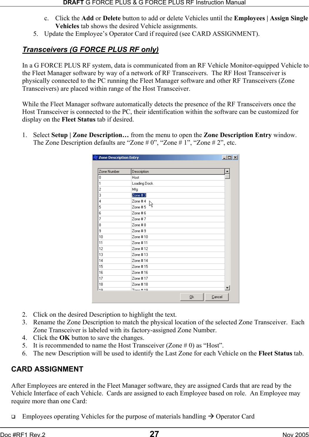
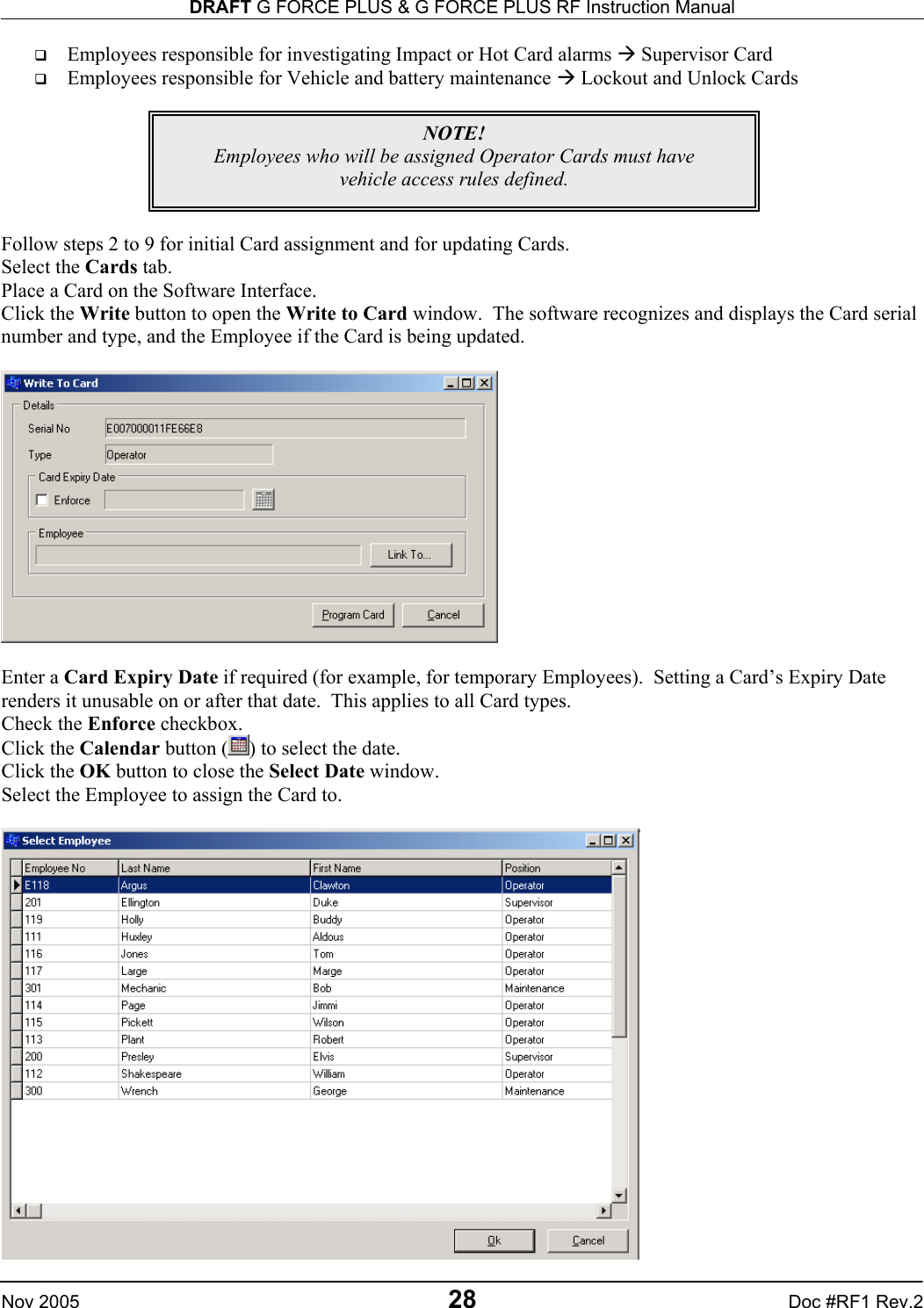
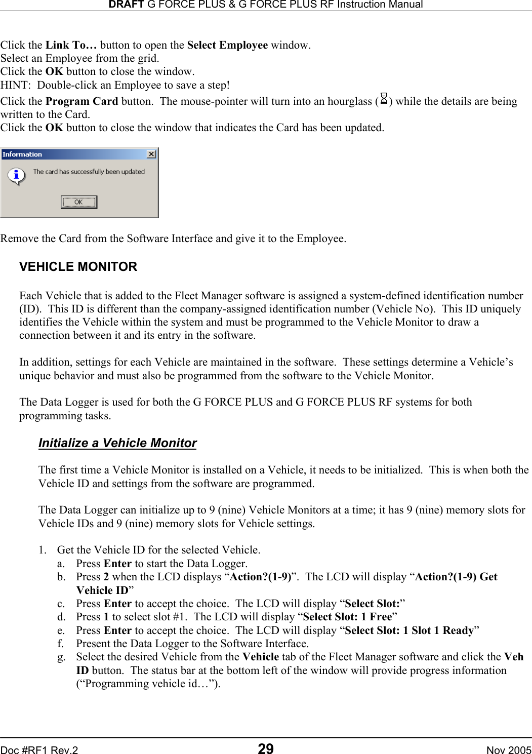
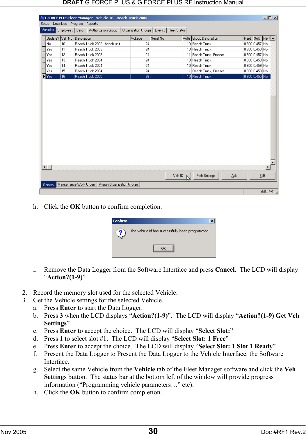
BMI Technologies Inc. Vehicle User Interface RFID Reader Users Manual
UserManual.wiki
>
BMI Technologies
>
VUI00 User Manual
Users Manual
Navigation menu
Upload a User Manual
Namespaces
Wiki Guide
HTML
PDF
Info
Views
User Manual
Discussion / Help
Navigation
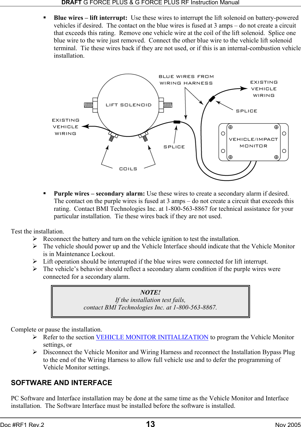
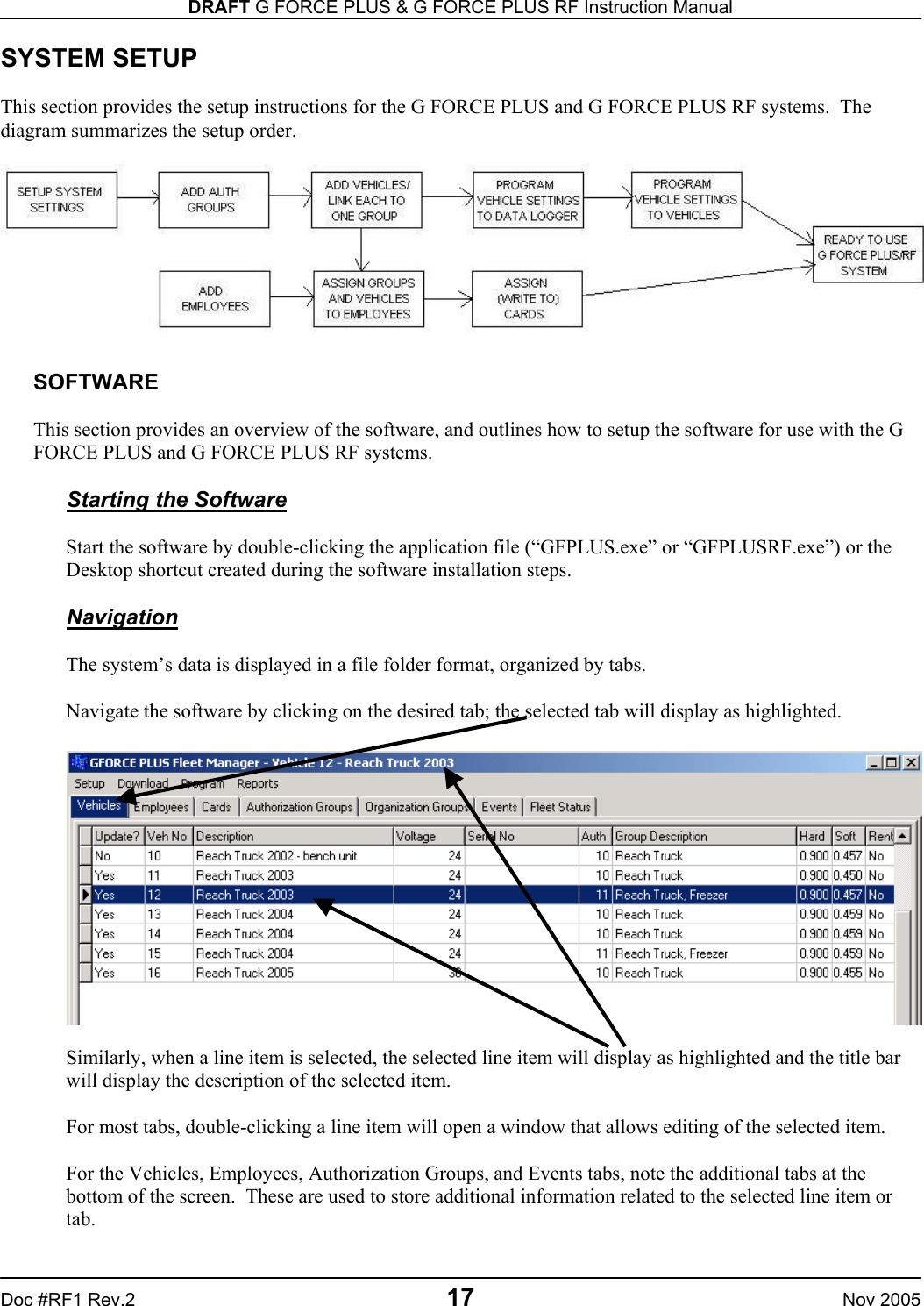
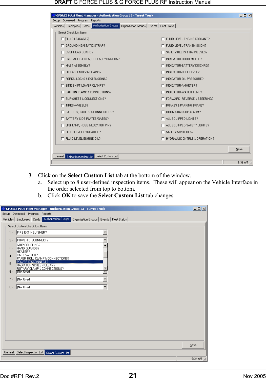
![DRAFT G FORCE PLUS & G FORCE PLUS RF Instruction Manual Nov 2005 22 Doc #RF1 Rev.2 Edit the Custom Checklist The Custom Checklist allows for an Authorization Group’s Vehicle Inspection Checklist to be customized. The software can store up to 200 fully editable user-defined items, and is preset with 18 common ones. To modify the list: 1. Select Setup | Custom Check List from the menu. 2. Double-click an item to edit it, or double-click a [Not defined] line to add to the list. 3. Type the text the way you want it to display on the 2x16-character LCD display of the Vehicle Interface. 4. Click the OK button to add the item to the list. 5. Click the OK button to save the changes. Edit an Authorization Group 1. Select the Authorization Groups | General tab. 2. Select the Authorization Group you want to edit from the grid. 3. Click the Edit button to open the Edit Authorization Group window. 4. Change the desired field on the General, Settings or Vehicle Defaults tab. NOTE! Changes to the settings of an Authorization Group require all Vehicles in the Authorization Group to be reprogrammed with the Data Logger.](https://usermanual.wiki/BMI-Technologies/VUI00/User-Guide-612009-Page-24.png)