BRYANT Furnace/Heater, Gas Manual L1001009
User Manual: BRYANT BRYANT Furnace/Heater, Gas Manual BRYANT Furnace/Heater, Gas Owner's Manual, BRYANT Furnace/Heater, Gas installation guides
Open the PDF directly: View PDF ![]() .
.
Page Count: 2
Installation Instructions
NOTE: Read the entire instruction manual before starting the
installation.
SAFETY CONSIDERATIONS
Improper installation, adjustment, alteration, service,
maintenance, or use can cause explosion, fire, electrical shock, or
other conditions which may cause death, personal injury, or
property damage. Consult a qualified installer, service agency, or
your distributor or branch for information or assistance. The
qualified installer or agency must use factory-authorized kits or
accessories when modifying this product. Refer to the individual
instructions packaged with the kits or accessories when installing.
Follow all safety codes. Wear safety glasses, protective clothing,
and work gloves. Have a fire extinguisher available. Read these
instructions thoroughly and follow all warnings or cautions
include in literature and attached to the unit. Consult local
building codes, the current editions of the National Fuel Gas
Code (NFGC) NFPA 54/ANSI Z223.1 and the National
Electrical Code (NEC) NFPA 70.
In Canada, refer to the current editions of the National Standards
of Canada CAN/CSA-BI49.1 and .2 Natural Gas and Propane
Installation Codes, and Canadian Electrical Code CSA C22.1
Recognize safety information. This is the safety-alert symbol/_.
When you see this symbol on the unit and in instructions or
manuals, be alert to the potential for personal injury.
Understand the signal words DANGER, WARNING, and
CAUTION. These words are used with the safety-alert symbol.
DANGER identifies the most serious hazards which will result in
severe personal injury or death. WARNING signifies hazards
which could result in personal injury or death. CAUTION is
used to identify unsafe practices which may result in minor
personal injury or product and property damage. NOTE is used
to highlight suggestions which will result in enhanced
installation, reliability, or operation.
FIRE, EXPLOSION, ELECTRICAL SHOCK
HAZARD
Failure to follow this warning could result in personal injury,
death and/or property damage.
Before installing or servicing unit, always turn off main
electrical and gas to unit and tag with appropriate lockout.
There may be more than one disconnect switch.
CUT HAZARD
Failure to follow this caution may result in personal iniury.
Sheet metal parts may have sharp edges or burrs. Use care
and wear appropriate protective clothing, safety glasses and
gloves when handling parts and servicing furnaces.
FIRE, EXPLOSION, ELECTRICAL SHOCK
HAZARD
Failure to follow this warning could result in possible
personal iniury, death and /or property damage.
The ability to properly perform service on this equipment
requires certain expertise, mechanical skills, tools, and
equipment. If you do not possess these, do not attempt to
perform any service on this equipment other than those
procedures recommended in the User's Manual.
Kit Part
KGAHA6101PSW
KGAHA6201PSW
KGAHA6301PSW
KGAHA6401PSW
Table 1 -Models
Used with Models
58HDV040
359BAY036040
58HDV060
359BAY036060
58HDX060
359AAV036060
PG9YAB036060
58HDV080
359BAY060080
58HDX080
359AAV036080
PG9YAB036080
359AAV048080
PG9YAB048080
58H DVl O0
359BAY0601 O0
58H DXl O0
359AAV060100
PG9YAB060100
INTRODUCTION
This instruction covers the installation of high-altitude pressure
switch kits in condensing furnaces. The switch set points are
shown on the label attached to the front of the switch.
KIT CONTENTS
The high-altitude pressure switch kit contains the following
items:
DESCRIPTION AND USAGE
This high-altitude pressure switch kit is required for the
installation of the condensing furnaces when installed with a
Category IV vent system at altitudes equal to or higher than 4000
ft. (1219 M) above sea level.
High altitude switch assembly
Installation instructions
1
1
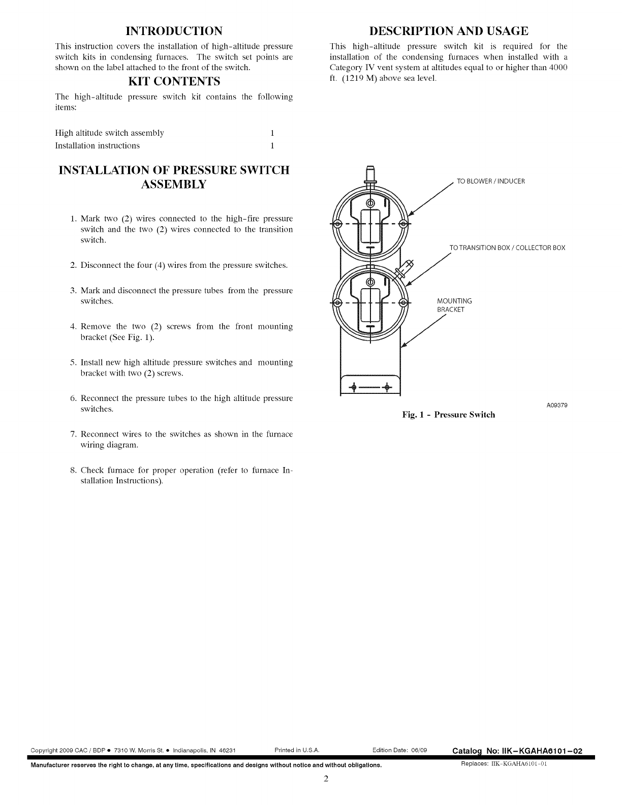
INSTALLATION OF PRESSURE SWITCH
ASSEMBLY TO BLOWER /INDUCER
1. Mark two (2) wires connected to the high-fire pressure
switch and the two (2) wires connected to the transition
switch.
2. Disconnect the four (4) wires from the pressure switches,
3. Mark and disconnect the pressure tubes from the pressure
switches.
4. Remove the two (2) screws from the front mounting
bracket (See Fig. 1).
5. Install new high altitude pressure switches and mounting
bracket with two (2) screws.
6. Reconnect the pressure tubes to the high altitude pressure
switches.
7. Reconnect wires to the switches as shown in the furnace
wiring diagram.
8. Check furnace for proper operation (refer to furnace In-
stallation Instructions).
TO TRANSITION BOX /COLLECTOR BOX
MOUNTING
BRACKET
Fig. 1 - Pressure Switch
Aog37g
Copyright 2009 CAC /BDP • 7310 W. Morris St. • Indianapolis, IN 46231 Printed in U.S.A. Edition Date: 06/09
Manufacturer reserve8 the right to change, at any time, specification8 and design8 without notice and without obligations.
2
Catalo_l No: IIK-KGAHAO101-02
Replaces: IIK KGAHA6101 01
