BTE Technologies DAQRETROFIT Strength measurement equipment. User Manual 40050053 rev A
BTE Technologies, Inc. Strength measurement equipment. 40050053 rev A
Contents
- 1. FCC Manual Addendum
- 2. Users Manual 1
- 3. Users Manual 2
Users Manual 1
BTE Technologies
Evaluation and Rehabilitation System
Manual
2

3
Customer Service
BTE strives to provide exceptional customer service. To access a Customer
Service Representative:
Phone 800.461.6888 (9am-6pm EST Monday thru Friday)
Cell 416.717.5789 (After-hours service)
Fax 416.398.9108
Email service@bteco.com
Class A Digital Device
This equipment has been tested and found to comply with the limits for a Class A
digital device, pursuant to part 15 of the FCC Rules. These limits are designed to
provide reasonable protection against harmful interference when the equipment is
operated in a commercial environment. This equipment generates, uses, and can
radiate radio frequency energy and, if not installed and used in accordance with
the instruction manual, may cause harmful interference to radio communications.
Operation of this equipment in a residential area is likely to cause harmful interference
in which case the user will be required to correct the interference at his own expense.
Do Not Change of Modify Any Components
Any changes or modifications, especially to the wireless components, not expressly
approved by BTE Technologies, Inc. could void the user’s authority to operate the
equipment.
Acceptable Antenna(s)
This device has been designed to operate with the antenna(s) listed below and having
a maximum gain of 2.7 dBi. Antennas not included in this list or having a gain greater
than 2.7 dBi are strictly prohibited for use with this device. The required antenna im-
pedance is 50 ohms.
Acceptable antenna(s) include:
1. Linx Technologies 916MHz 1/4 Wave Whip Antenna (ANT-916-CW-QW)
To reduce potential radio interference to other users, the antenna type and its gain
should be so chosen that the equivalent isotropically radiated power (e.i.r.p.) is not
more than that permitted for successful communication.
Preventing interference between the wireless components
Interference, which can result in an inability to acquire accurate data, may occur in
the following scenarios:
a. The antennas of any wireless components are within 3 feet of each other (e.g.
the antenna on the new DAQ Box is within 3 feet of the antenna on the Heart Rate
Transmitter).
b. There is not a direct line of sight between the antennas of the wireless compo-
nents. In addition, any metal that is between the antennas will cause interference.
You may prevent interference by maintaining your system in the following manner:
a. Do not allow the Heart Rate Transmitter to fall on the floor.
b. Regularly check the USB cable and power cable that are attached to the new
DAQ Box.
c. Verify the antennas are in good working order and properly secured.
You may also prevent interference by using the following guidelines:
a. Place the new DAQ Box in a location that ensures the antenna of the new DAQ
Box will always be at least 3 feet from the antenna on the Heart Rate Transmitter.
b. Verify there is a direct line of sight between the DAQ Box antenna and the Heart
Rate Transmitter antenna.
4
TABLE OF CONTENTS
5
Important Information .....................................................................................9
Conventions and Symbols Used....................................................................12
Assembling the Equipment Upon Arrival......................................................13
Functional Range of Motion (FROM) Pegboard Assembly..........................26
The Basics in Using the ER System ..............................................................31
Installing the Software ....................................................................................32
Administration Menu.......................................................................................40
Clinic Information .............................................................................40
Practitioner Information ...................................................................41
Environmental Settings....................................................................42
User Manager....................................................................................44
Import and Exporting in ODES ........................................................45
Heart Rate Comments ......................................................................48
Job Demand Templates....................................................................48
Protocol Hibernation ........................................................................49
Remove Current Case ......................................................................50
Calibrating the Equipment..............................................................................51
Calibration of the Hand Grip............................................................52
Pinch Grip Calibration......................................................................54
Algometer Calibration ......................................................................55
FOCUS Calibration ...........................................................................59
Universal Task Master Calibration ..................................................60
Weight Verification ...........................................................................64
Auto Calibration................................................................................66
Calibration Reports ..........................................................................67
Adding a Client ................................................................................................67
Adding a Client Case ......................................................................................69
Finding a Client/Case......................................................................................77
Adding a Test to a Client ................................................................................78
Removing a Test from a Client.......................................................................79
Additional ODES 2004 Software Features.....................................................80
File Menu ...........................................................................................80
Database Utilities.........................................................................80
Compacting and Repairing a Database .......................................82
Backing Up Your Database..........................................................82
Restore Database........................................................................83
Log Off and Exit ...........................................................................83
Calibration Menu...............................................................................83
Calibrate Equipment.....................................................................83
Verifying Calibration.....................................................................85
Calibration Reports ......................................................................85
Statistics Menu .................................................................................86
Employer Information...................................................................86
Client Status Information..............................................................86
Client Information.........................................................................87
Referral Information .....................................................................87
6
Insurance Information ..................................................................87
Statistical Inquiries .......................................................................87
Real Time Analysis ......................................................................88
Exporting Data .............................................................................90
Snapshots....................................................................................93
Forms Menu ......................................................................................95
Utilities Menu ....................................................................................95
Heart Rate Monitor.......................................................................95
Heart Rate Report........................................................................96
Sitting and Standing Tolerance....................................................96
Post Offer of Employment Software Menu .....................................98
POET Receipts ............................................................................98
Set Standards ..............................................................................99
POET Standards Report ..............................................................100
POET Summary Report ...............................................................103
POET Detailed Summary Report.................................................106
Export POET Results...................................................................111
Digital Capture Menu......................................................................112
Help Menu........................................................................................113
Help Manuals...............................................................................113
About............................................................................................113
Templates.........................................................................................................115
Super Protocols...............................................................................................119
Self Reports Menu...........................................................................................120
Dallas Pain Questionnaire..............................................................120
McGill Pain Questionnaire .............................................................120
The Neck Disability Index (NDI).....................................................120
The Oswestry Questionnaire .........................................................121
Patient Review Questionnaire .......................................................121
Superficial Tenderness ..................................................................121
Symptom Intensity Rating..............................................................122
Waddell Signs .................................................................................123
Physical Demands Analysis ..........................................................123
Creating Custom Self Perception Tests .......................................123
EPIC Hand Function Sort (Optional Upgrade)...............................................125
EPIC Spinal Functional Sort...........................................................................126
Cardiovascular Menu ......................................................................................128
Astrand ............................................................................................128
Bruce Treadmill...............................................................................129
Cardiovascular Intake ....................................................................129
Modified Canadian Aerobic Fitness Test......................................130
Single State Treadmill ....................................................................132
Customized Cardiovascular Tests ................................................133
Creating a Non-Integrated Work Simulation Protocol .................134
Exercise Program/Cervical Conditioning......................................................136
Comments........................................................................................................138
7
Validity Analysis..............................................................................................141
Reports.............................................................................................................141
The BTE Dual Inclinometers...........................................................................148
Performing Spinal Range of Motion Evaluations.........................150
Guidelines to Locating the Landmarks.........................................150
Cervical Range of Motion...............................................................151
Thoracic Range of Motion..............................................................153
Lumboscaral Range of Motion ......................................................155
Determining the Degree of Ankylosis...........................................157
Performing Extremity range of Motion Evaluations ....................157
Using the Small Goniometer Feature............................................159
The BTE Goniometer.......................................................................................160
Performing Range of Motion Tests ...............................................161
Customizing the Goniometer Tests ..............................................164
Performing a Range of Motion Test with the Goniometer...........167
Range of Motion Protocols ............................................................168
The Hand Grip..................................................................................................180
Using the Hand Grip for a Pre-Programmed Strength Protocol .181
Protocol Information ......................................................................184
Standard Hand Grip .....................................................................184
Modified Maximum Voluntary Effort .............................................186
Rapid Exchange...........................................................................188
Creating a New Hand Grip Test .....................................................190
The Pinch Grip.................................................................................................192
Using the Ping Grip for a pre-programmed Strength Test Protocol 193
Protocol Information ......................................................................196
Key Pinch.....................................................................................196
Tip Pinch......................................................................................199
Palmar Pinch................................................................................201
Creating a Custom Pinch Grip Test ..............................................203
The BTE Algometer .........................................................................................205
Using the Pressure Algometer for a Pre-Programmed Strength Protocol
..........................................................................................................208
Fibromyalgia Protocol....................................................................222
ER Platform......................................................................................................225
Standard Accessories ....................................................................226
Multiplanar Accessory Housing Joint...........................................228
ER Shelves ......................................................................................231
Adjusting the Height and Orientation of the ER Arms ................236
Isometric Strength Testing.............................................................................241
Work Simulation Tests....................................................................................244
Integrated Lifting and Carrying Tests...........................................246
EPIC Lifting Capacity Protocol (Optional Upgrade).....................251
The Universal Task Master .............................................................................255
Functional Range of Motion ...........................................................................263
BTE Digital Radio Frequency Heart Rate Monitor ........................................278
8
Placement for the BTE Digital Radio Frequency HR Monitor .....279
Body Positioning ............................................................................280
Heart Rate Receiver Testing ..........................................................282
Recommended Care and Maintenance Schedule.........................................283
Transporting the Equipment ..........................................................................285
End User License Agreement.........................................................................286
Troubleshooting ..............................................................................................289
Data Acquisition Box.......................................................................289
Inclinometer and Goniometer.........................................................290
Hand Grip, Pinch Grip, Algometer, and FOCUS............................291
UTM...................................................................................................296
Heart Rate Monitor...........................................................................297
BTE Training Programs ..................................................................................298
9
Important Information
BTE Technologies Inc. - Baltimore
7455-L New Ridge Road
Hanover, MD 21076
Telephone: (410)850-0333 or (800) 331-8845
Facsimile: (410)850-5244
BTE Technologies Inc – Denver
2390 East Crescent Parkway, Suite 120
Englewood, CO 80111
Telephone (720) 266-0123 or (800) 206-2972
Facsimilie (720) 266-0120
Internet Support
Web Site: www.BTETech.com
Customer Service
Telephone: (800) 331-8845
Email: service@bteco.com
Copyright Information
Information in this document is subject to change without notice. Companies, names and data used in
examples are fictitious unless otherwise stated. No part of this document may be reproduced or
transmitted in any form or by any means, electronic or mechanical, for any purpose, without the express
written consent of BTE Medical Inc. BTE may have patents or pending patent applications, trademarks,
copyrights or other intellectual property rights covering the subject matter in this document. The
furnishing of this document does not give you license to these patents, trademarks, copyrights or other
intellectual property except as expressly provided in any written license agreement from BTE Medical Inc.
© 2003 BTE Technologies Inc. All rights reserved.
10
Credits
The following individuals were involved in the development of this manual.
Elizabeth Chapman B.Sc.Kin.,CK Customer Service Manager
Sarah Graham, B.Sc.Kin.,CK Kinesiologist
Jeries Hanoun, M.B.A Media Manager
David Lithwick B.Sc., B.A. Chief Technology Officer
Navin Ramrattan Production Manager
Tobi Weightman B. HSC Customer Service Representative
Paul Zhang M.Sc. Electrical Engineer
Technical Specifications
The following outlines the electrical components of the BTE Evaluation and Rehabilitation System:
Input Voltage:
Europe - 220/230/240VAC
North America – 110VAC
50/60 Hz
Input Current:
Europe - 4 Amp
North America – 8 Amp
The BTE Evaluation and Rehabilitation System has been certified by Entela (File No. 8771). All the tools
(applied parts) for the system are Type B. The system has been manufactured to be used in normal
conditions. Do not use the system beside high magnetic fields, or x-rays. Cell phone usage within 30 feet
of the system may have an impact on the accuracy of the heart rate monitor readings.
The BTE tools are to be used only in the ports and manner specified in this manual. Any modifications or
use of non-BTE parts can cause damage to the product. Contact BTE Medical Inc for replacement parts if
required.
Safety Considerations
BTE Medical makes every effort to design and manufacture products, which meet and exceed the highest
safety standards. The following information provides recommendations for safe use of the equipment.
The BTE Evaluation and Rehabilitation System must only be operated on a level surface.
The recommended maintenance program for your system is outlined in a later section of this manual. This
program will ensure your equipment will function properly and safely for many years. If at any time your
system is not working safely, the evaluator should contact the BTE Medical Customer Service
Department for assistance. Never attempt to repair the electrical components of the system. Disconnect
the power source for any other repairs.
This equipment is to be used and/or supervised by qualified healthcare professionals who has knowledge
in anatomy, exercise physiology, biomechanics, psychology, pathology, and an understanding of work,
rehabilitation and disability management principles. Prior to use of this equipment it is recommended the
evaluator read the information in this manual as well as obtaining certification from BTE Medical. Prior to
11
testing any clients it is suggested a sample test be completed with a co-worker familiar with the system to
improve your comfort with the system.
Prior to initiating system use with a client, it is recommended that the physical health questionnaire be
completed with the client along with an intake interview to determine if there are any medical
contraindications. Resting blood pressure and heart rate should be measured to ensure they are within
safe limits for testing as per relevant research and guidelines. If any medical contraindications are
identified clearance should be obtained from the client’s primary care practitioner prior to initiating
functional testing or rehabilitation.
During functional testing, the client’s heart rate and other physiological parameters as appropriate should
be monitored. Testing should be stopped if the heart rate is above safe limits as outlined in relevant
research and guidelines or if other physiological parameters are above safe limits. Body mechanics are a
good indicator when a client is performing an unsafe activity and is at risk of injury. It is the evaluator’s
responsibility to monitor the client’s body mechanics and either alert the client to alter their movement or
terminate testing.
The equipment has been designed with double locks on all the attachments to the Evaluation and
Rehabilitation (ER) System arms. The evaluator must ensure that both the locking pin and the tightening
mechanisms are secure before allowing a client to push or pull on an accessory attached to the ER arm.
When using the weights for calibrating or for functional testing or rehabilitation, care needs to be taken to
prevent injury. When stepping on and off the platform care needs to be taken to prevent tripping.
The information presented in this manual is given in good faith and is to the best of our knowledge
accurate. However, anyone who uses this information in any way does so entirely at his or her own risk.
Neither BTE Medical Inc., its officers nor their representatives can accept any responsibility for any
damage or injury incurred as a result of information presented here except under the terms of the product
warranty.

12
Conventions and Symbols Used
This instructional manual will use several common conventions to assist in the reading and understanding
of the material presented. The following is a summary of the typographical conventions:
Words you type appear in “quotations”.
Buttons you click on with the mouse appear in a bold font.
If a task requires you to choose from a menu, the manual separates menu commands with a vertical bar.
Therefore, this manual uses File | Save As to indicate that you should open the File menu and choose the
Save As command.
In addition to typographical conventions, the following icons are used to set off various pieces of
information and to make them easily recognizable:
The New Term icon appears when a new term is addressed and will include a definition to
help reinforce that term.
The Troubleshooting icon may appear at the end of some sections. This offers
suggestions to help you through your troubleshooting. The majority of the troubleshooting
tips can be found in the appendix of the manual.
The Tips icon will provide you with tips that offer shortcuts and quick solutions to common
problems.
You will find the Important Icon when it is mandatory or strongly advised that you carry
out an action before progressing to the next.
Type B Classification. This label indicates that the equipment provides a particular
degree of protection against electrical shock, particularly regarding allowable leakage current and the
reliability of the protective earth connection. The Hanoun Evaluation and Rehabilitation system meets or
exceeds the IEC 60601-1, Ed 2:88 +A1:91 and A2:95, IEC 60601-1-1, CAN/CSA-C22.2 No. 601.1-
M90/UL 2601-1(1997).
Attention, Consult Accompanying Documents. This symbol is located on the data
acquisition box adjacent to the LED indicator.

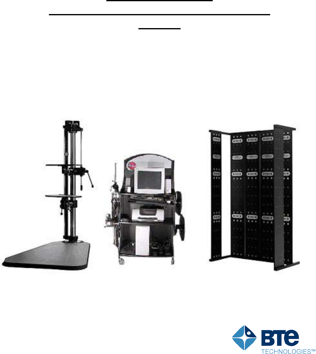
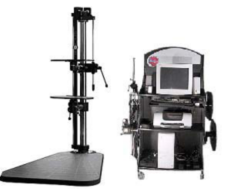
Assembling the Equipment Upon Arrival
Your ER System will arrive on several skids. The shipping company will place the ER Platform (including
the base and post) in the location you specify to them. The post is attached to the base by four screws
with an Allen key. The Computer Management Stand is to be placed to the right of the system. The
FROM pegboard may be placed anywhere in close proximity to the system (no more than 20 feet away).
All the equipment must be assembled on a level surface.
The following is the recommended order in which to assemble your equipment:
Place the ER Stand where you would like to have it
Assemble the Computer Management Stand to the right of the ER Stand
Assemble the FROM pegboard
Assemble tools on Computer Management Stand
Connect the computer
It is recommended while unpacking the equipment that you review your packing slip, to make sure you
have received all the required parts. If there is anything missing from the shipment please contact
Customer Service immediately so replacements can be provided.
Computer Management Stand Setup
The computer management stand is partially assembled when you receive it. To complete assembly you
will need to attach three shelves at the front of the stand and one shelf at the bottom back of the stand in
order for it to be fully operational.
Required Tools and Equipment:
8 X 1” screws
Allen Key
Phillips or square head screwdriver
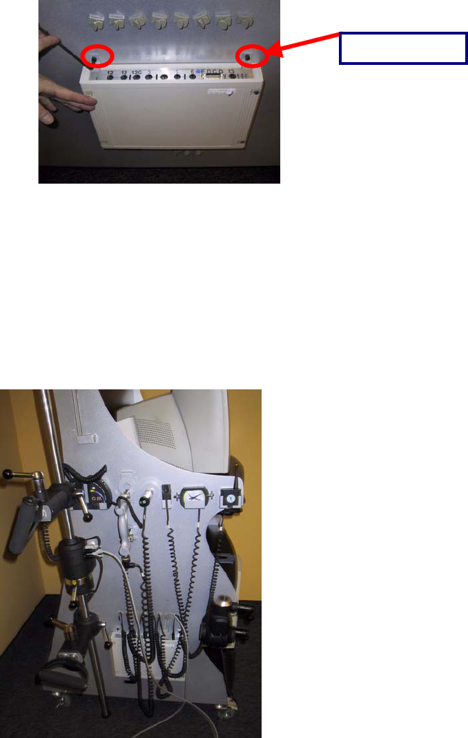
Dismount/Assembly of Computer Stand
To identify the front of the stand locate the Hanoun sticker at the top. The back of the stand is
distinguished by a random series of holes.
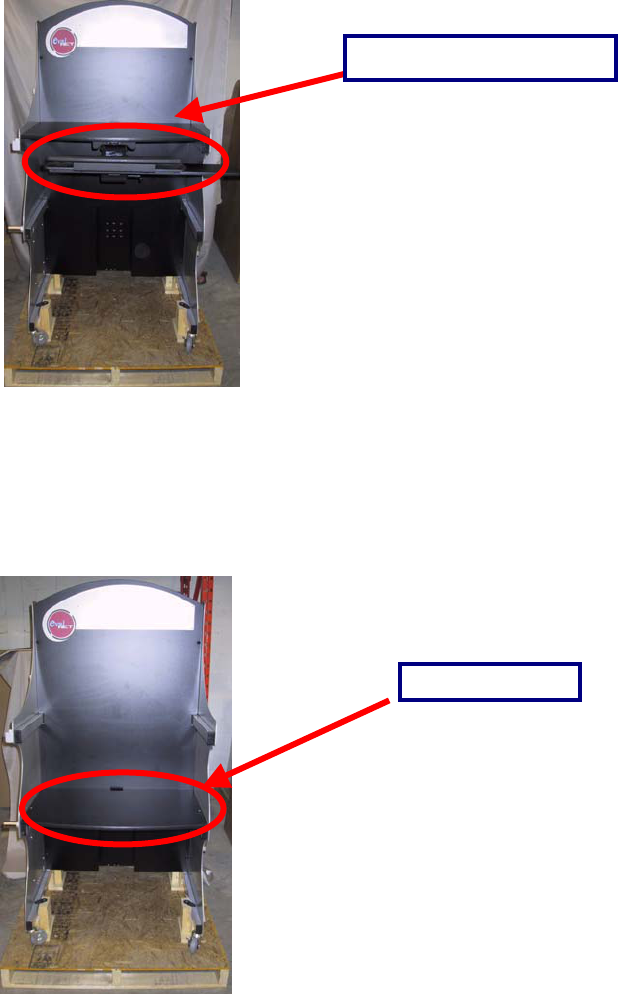
To dismount the Computer Stand from the skid unscrew and loosen the bolts near the bottom rails (as
shown below). There is a bolt near each wheel. When the bolts are removed, slide the stand off the skid.
Shelf 1 is the shelf with the keyboard drawer attached to it. This shelf will support the computer monitor.
It needs to be screwed to the top set of rails on the stand.
Bolts that secure
stand to skid.
14
2 of the 1” screws are inserted into the rails along the inside of each side panel through holes in the holes
in the top.
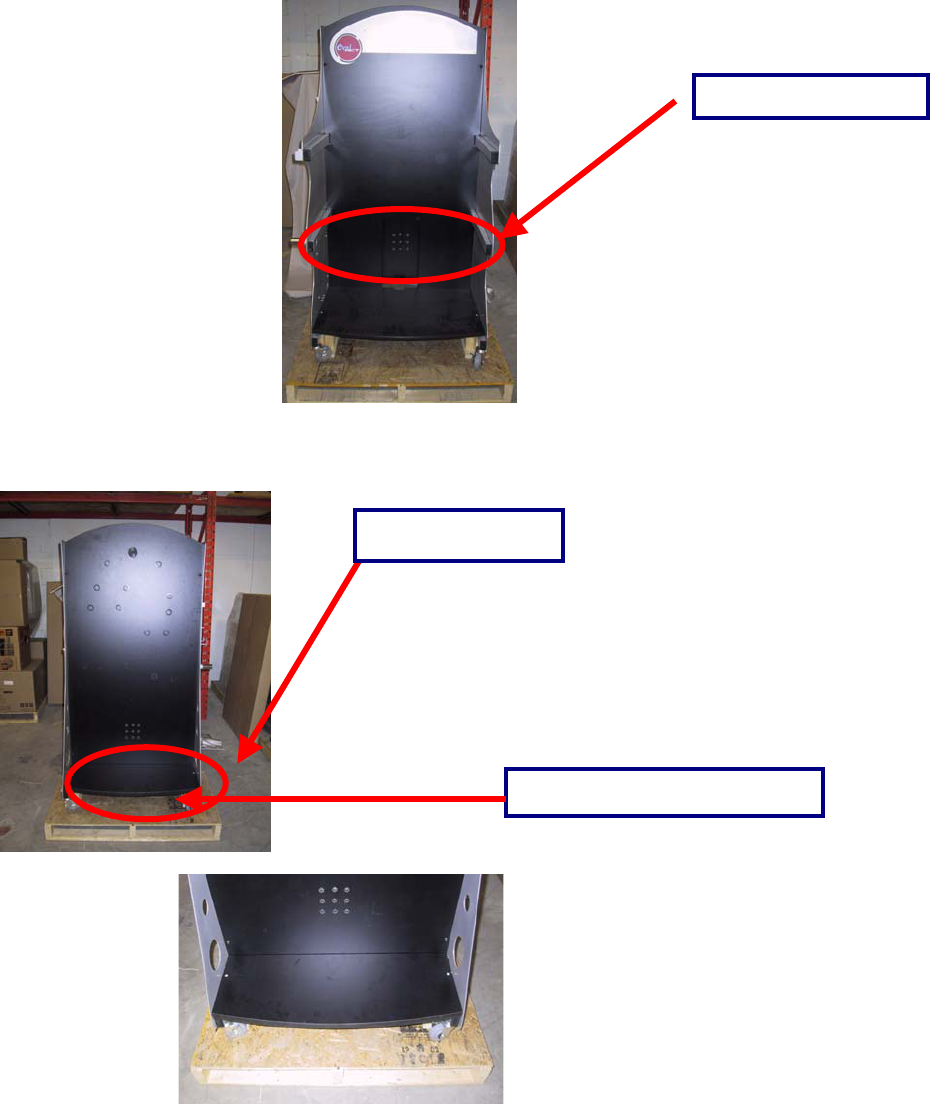
Shelves 2 and 3 are identical in nature. Shelf 2 is attached to the two rails in the middle of the front of the
stand with 2 of the 1” screws. This shelf will support the computer printer.
Shelf 3 is attached to the bottom rails of the front of the stand with 2 of the 1” screws. This shelf will
support the computer tower.
Shelf 1 with keyboard
Shelf 2, middle.
15
Shelf 4, the smallest of the shelves, is attached to the bottom rails on the back of the stand with 2 of the
1” screws. This shelf will support all of the masked weights.
The front of the completed Computer Management Stand with the 4 shelves attached should look like the
following:
Shelf 3 (bottom, front).
Shelf 4 (back).
Close up of back, bottom shelf.
16
The next step in the set up of the Computer Management Stand is the installation and mounting of all the
other equipment. As mentioned earlier the computer monitor rests on the top shelf, the printer and
computer speakers rests on the middle shelf, and the computer tower rests on the bottom shelf of the
front of the stand. The back of the stand and both sides of the stand also hold numerous pieces of
equipment.
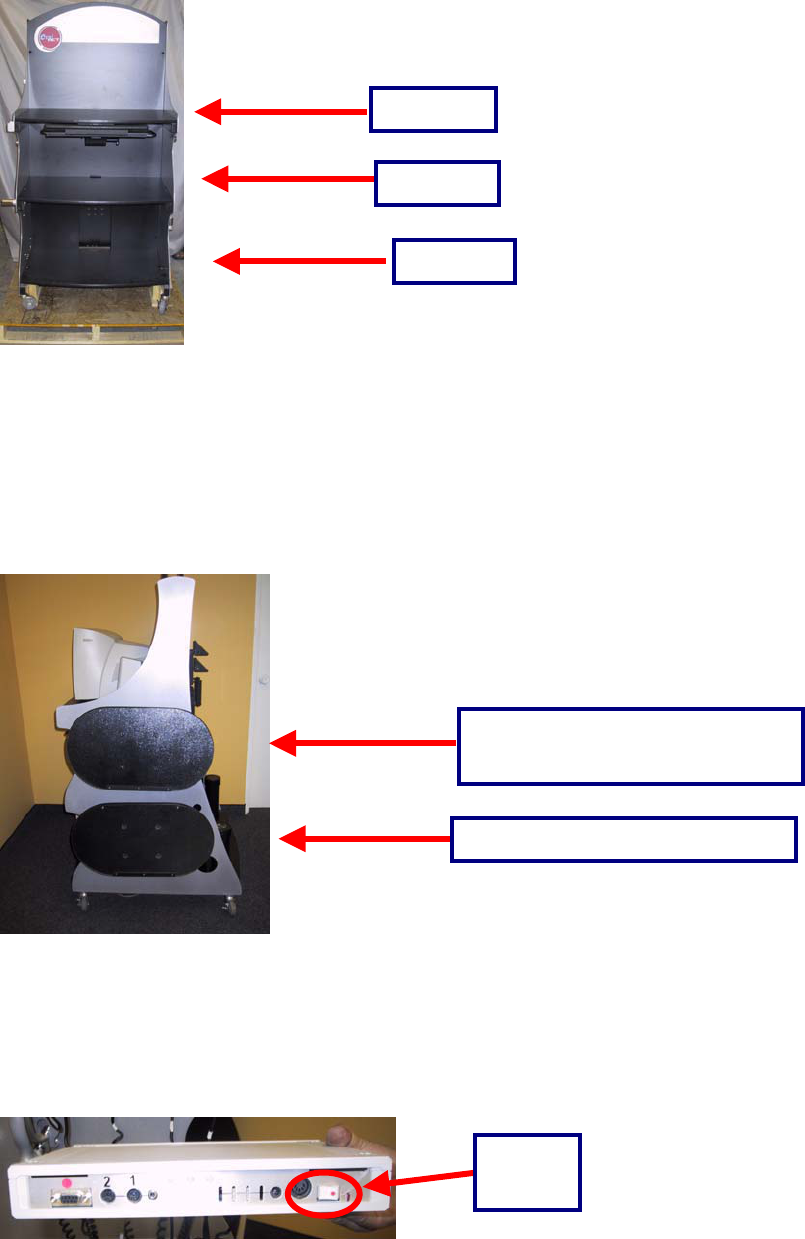
The right side of the stand (when facing the front of the stand) holds the two FOCUS shelves as shown
below. The shelf with the elbow attachment is mounted below the shelf with the straight pin attachment.
The left side of the stand holds the Data Acquisition Box, the Inclinometer, the Goniometer, the Handgrip
Dynamometer, the Pinchgrip Dynamometer, the Algometer, the Universal Task Master (UTM), the
FOCUS load cell, and the Heart Rate Monitor. The first piece of equipment to be installed on the left side
of the stand is the Data Acquisition Box. The one narrow end of the Data Acquisition Box with the power
switch faces the ground.
Shelf 1
Shelf 2
Shelf 3
Shelf with straight pin attachment.
Shelf with elbow attachment.
Power
switch.
17
The Data Acquisition Box is secured to the stand by mounting clips and tightened with an Allen key. The
Allen key is provided with your system.
The power cord for the Data Acquistion Box is fed through the side of the computer management stand to
the power bar. The serial cord attaches to the back of the data acquisition box and is fed through the side
of the computer management stand and connected into the serial port in the computer.
All the power cords for the testing equipment on that side are plugged into this Data Acquisition Box. As
you will notice, each cord is labeled with a number and/or a letter, which corresponds to the same number
and/or letter on the top of the Data Acquisition Box. Provided for you, and already mounted above the
Data Acquisition Box, are clips for each cord coming out of the Data Acquisition Box. This prevents
constant bending of the cords at the connection to the box and prevents wear and tear on the cords.
Each piece of testing equipment on the left side of the stand has its own specific mounting apparatus.
Use the picture below as a guide to see where each piece of equipment fits. The coiled power cords for
the equipment should be plugged into the appropriate location on the Data Acquisition Box. When
plugging the equipment into the Data Acquisition Box make sure the pins are lined up properly to avoid
damaging the connectors.
Mounting Clips.
18
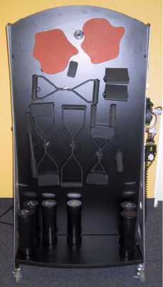
The back of the Computer Management Stand is designed to hold all of the attachments for the FOCUS
and UTM. This includes all of the different kinds of handles (straight bar, wide handles, palmar handles,
etc.) Use the picture below to see the optimum placement of the various attachments. The smaller shelf
on the back of the stand holds the masked weights.
Connecting ER to the Computer Diagnostic System
19
In order to connect the ER to the Computer Diagnostic System you will need the following items:
ER Stand
Computer
3 Black Coiled two-way Connector Cables (labeled 3E, 1B and 2T)
One Data Acquisition Box
One Computer Serial Cable
One black AC power cord
One heart rate monitor cable (with one round and one square end)
When you are ready to begin, identify all of the above components, and then follow these steps:
20
Attaching the Upper Accessory Arm Cable
Upper
Cable (2T)
on upper
arm
Base of the ER
system
2T insertion on
the base of the
ER system
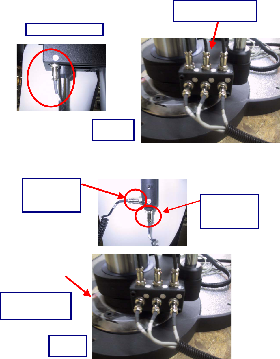
21
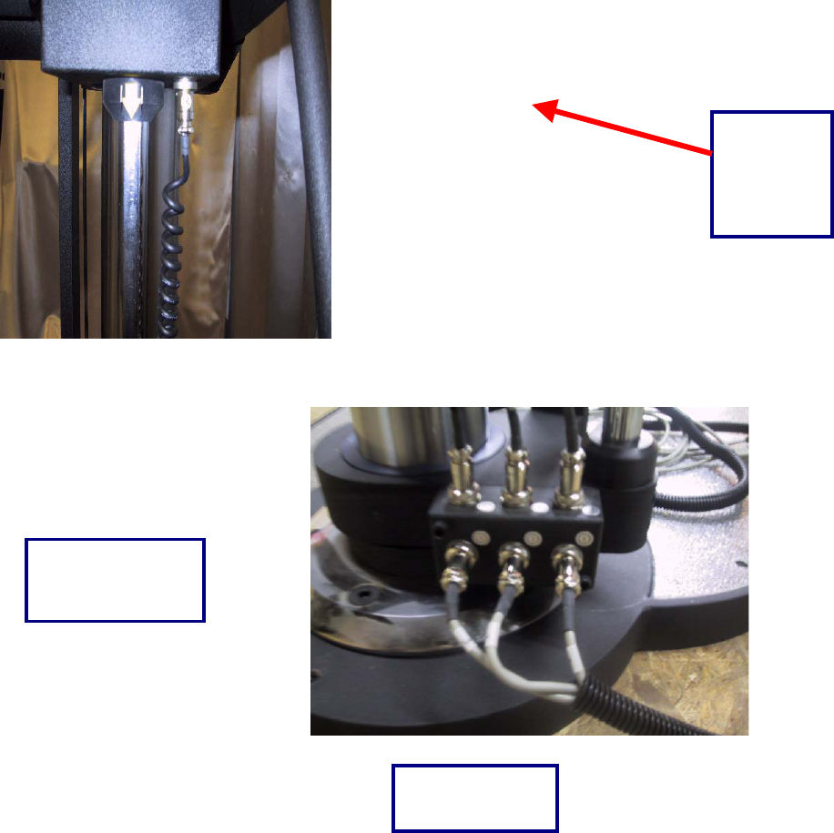
Attaching the Lower Accessory Arm Cable:
Connecting the FOCUS Load Cell Head to the Junction Box
1B Cable for Lower Arm
Base of ER
System
Load Cell Head
connects to the 3E
port on the
j
unction box
3E insertion on the
j
unction box at base of
the ER stand
Base of
ER Stand
1B insertion at the base of
the ER System
3E cord connects
to port on the
j
unction box
22
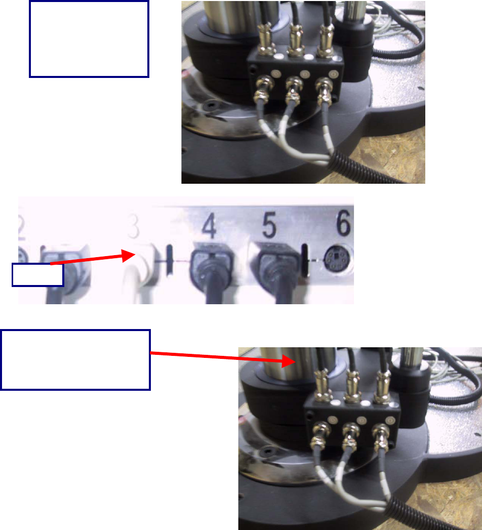
Connecting the Junction Box Components (Load Cell, Upper Shelf and Lower Shelf) to the
Computer Stand
Port #3
This is the #3 cable
which is attached to
the number 3 port on
the Data Acquisition
Box.
This is the number 2 cable,
which is plugged into the
number 2 port on the back of
the Data Acquisition Box.
23
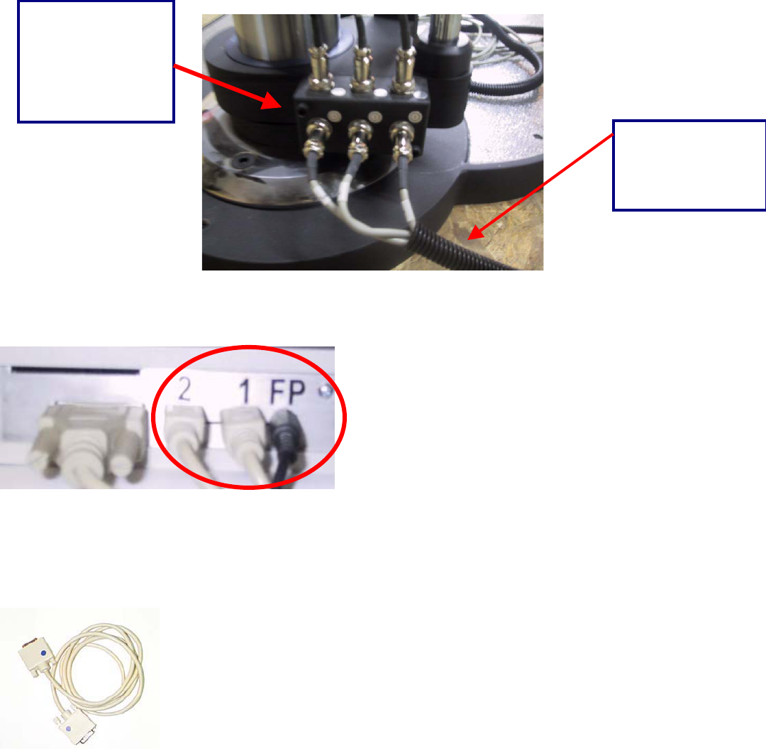
Connecting the UTM to the Data Acquisition Box
Within the packaging of your system, you will find one more gray serial cord with blue markings on it.
This cable will be used to connect the Universal Task Master to the front of the Data Acquisition Box.
Locate the back of the Universal Task Master (marked with a blue dot). One end of the serial cord is
connected to this side of the UTM. To allow for communication between the UTM and the Data
Acquisition Box, the other end of the serial cord (also marked with a blue dot) must now be connected to
the ‘TM’ port on the Data Acquisition Box.
This is the number 1
cable, which is
plugged into port
number 1 on the
back of the Data
Acquisition Box.
A black plastic wrap
is then used to
secure the loose
wires.
24
See below for the placement of the cables from the right and left load cells. Match the blue dots to attach
the cable that connects to the Data Acquisition Box.
You have now connected the Data Acquisition Box to the computer stand. The Data Acquisition Box
should now be in communication with the UTM.
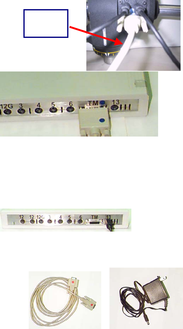
Setting Up Your Data Acquisition Box
Take a moment to view the Data Acquisition Box. You will notice that the front of the box has nine outlets
and a green light bulb.
In order to use your ER System, connect the Data Acquisition Box to both the computer and the ER
System. In order to do so, locate the gray serial cords marked with red dots and a black power supply
cord supplied with your system.
The serial cord connects the Data Acquisition Box to the serial port on the back of your computer.
Connect the female end of the serial cable to the back of your Data Acquisition Box. For your
convenience, a red dot has been placed over the correct insertion for the cable -- simply match the red
dots together.
Match dots
and connect
cord
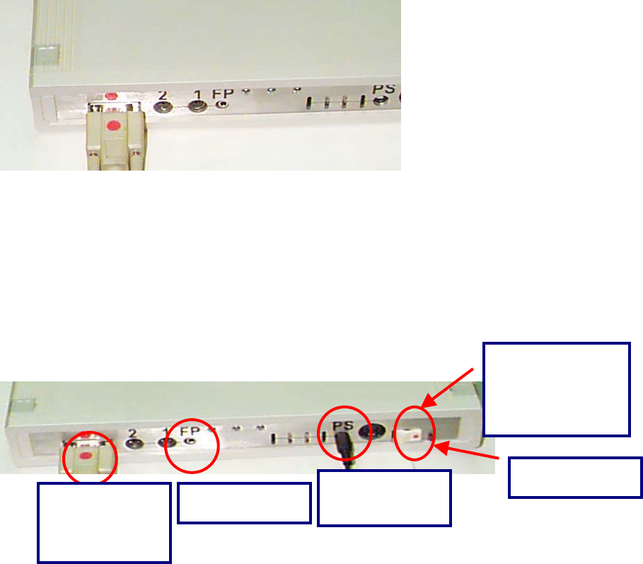
25
The same is true on your computer tower. Simply take the opposite end of the serial cord and connect it
to the proper port on the back of the CPU – this is also identified with a red dot for your convenience. Do
not plug the serial cable into a converter and then into a USB port in the computer.
To connect the power supply to your Data Acquisition Box, insert the single prong or pin into the “PS” port
located at the rear of you Data Acquisition Box. The opposite end of the power supply should be plugged
into a power adapter. Switch the Data Acquisition Box on -- the green light on the front of the box will light
up to indicate that the box is receiving power.
Attachments
The following is a list of ports that each integrated tool connects to:
1 – Bottom Shelf
2 – Top Shelf
3 – FOCUS Load Cell
4 – Hand Grip
5 – Pinch Grip
6 – Algometer
12 – Inclinometers
12G – Goniometer
12 – HR receiver
TM –Universal Task Master
You have now connected almost all of the basic components necessary for communication between the
ER hardware and ODES software. The final step is to plug the power cord to the power outlet.
On/Off Switch
PS= Power
Supply Cable
FP= Foot Pedal Serial Cable
connects to
serial port in
computer
Red Light – When
on means a tool
has shorted out the
Data Acquisition
Box
26
Functional Range of Motion (FROM) Pegboard
Assembly
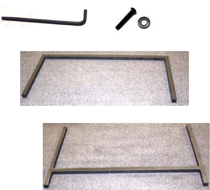
List of Parts:
6 MTM Panels 1-6 (Each has Zone A, B, and C)
2 Brackets Top/Bottom
24-1/4” blk. washer
24-1/4 x 20 x 1 ¼ BHCS
30- Pin blk
1 5/32 Allen Key
Installation
1. Locate your 5/32 Allen Key, 24 black washers and 24 1/ ¼ screws.
27
Locate the top and bottom brackets
Top Bracket
Bottom Bracket
28
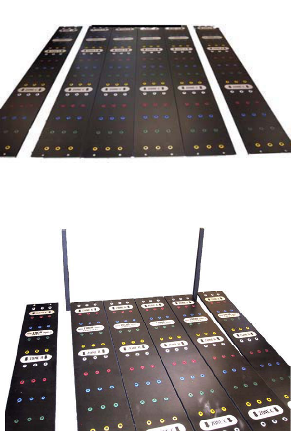
Arrange the MTM Panels on the floor in the proper sequence. The order is as follows (from left to right):
Panel 6, 1, 2, 3, 4, and 5.
Place the top and bottom brackets so that the middle four MTM panels can be attached. You may want
to move panel 6 and 5 aside for the time being. Panels 1-4 need to be attached using the 5/32 Allen
Key, the 1 ¼ screws and the washers. Attach the top bracket to the panels prior to attaching the bottom
bracket.
Once the top and bottom brackets have been attached, you are now ready to attach panel 5 and 6. This
should be done one panel at a time, starting with panel 6 on the left. Screw one bolt into the top bracket
and one bolt into the bottom bracket in order to line up the panel with the bracket. You may then attach
the second set of bolts in order to set the panel in place. Repeat this procedure for panel 5 on the right
hand side.
29
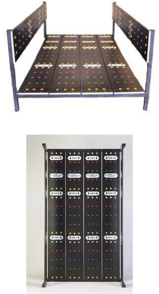
You may now tilt the FROM board into an upright position and place the 30 black pegs in one of the
zones to prepare for testing.
Once upright the FROM board can be located near the ER system, up to 20 feet away from the computer.
30
Once you have set up your system please complete the registration form and fax it to Customer Service
at (416) 398-9108. If you have any difficulty assembling or using the system our Customer Service
department can provide you with assistance by calling (800) 461-6888 X2.
Please take the time to review the rest of this manual to better understand the Hanoun hardware and
software. It is strongly recommended that evaluators using this system receive appropriate training and
get certified as Hanoun Evaluators. Information on training can be obtained in the appendix of this
manual, by contacting your sales representative or by registering on-line at www.hanoun.com.

31
The Basics in Using the ER System
If your system was purchased with a computer, the ODES software comes pre-installed and all the
required software components should be unlocked prior to shipping.
The following information will provide those evaluators with information on installing the software.
Instructions for Software Installation
Prior to loading the ODES software onto a computer please check to make sure your computer meets the
minimum recommended software and hardware requirements.
COMPONENT REQUIREMENT
Computer
Windows
Memory
Disk Space
Components
Network
Motherboards
500 MHz Processor
Window 98 Second Edition, ME, XP or 2000 is required to run the
ODES program. We do not suggest XP Home Edition. Go to
www.microsoft.com to get the latest service patches for your
operating system.
256 MB of RAM is recommended
500 MB of free disk space
800 x 600 screen
An SVGA high resolution color monitor
A PS/2 mouse or compatible pointing device
USB port for the Data Acquisition Box A color ink jet or laser
printer
Speakers
In order to connect your computer to other computers via a
network, cables and a Windows-compatible network adapter
(network card) are required.
**we prefer**
Intel Chipset Motherboards
Intel Pentium CPU’s
**Please note that we do not provide technical support for USB**
**Palm Pilot type software will interfere with the data acquisition device**
32
Installing
Please ensure that you have exited all programs prior to loading ODES 2004.
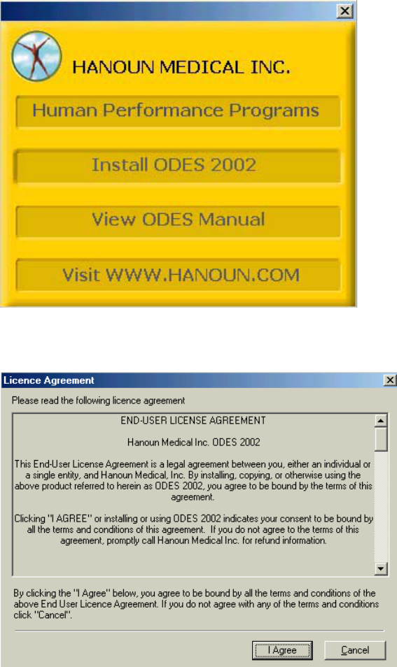
Insert the ODES 2004 disk into the CD-ROM drive and wait a few moments. A screen will appear giving
you a variety of choices. You may view a PowerPoint presentation about our systems (Human
Performance Programs), install ODES 2004, view the ODES manuals or visit our website. To install the
software, click on Install ODES 2004
After choosing to install ODES, you must accept the license agreement to continue the installation
process.
33
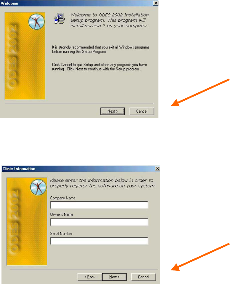
Click on Next to continue the installation process, or click Cancel if you need to close any currently
running programs before continuing.
Follow the instructions on the page in order to complete the installation. Please ensure that the following
form is filled out correctly. The serial numbers need to be typed exactly as they are seen on the machine
(i.e. FCE…). You can locate this serial number on your registration form or packing slip. Please call our
customer service department or your dealer if you have trouble locating the machine serial number for
your unit. Click Next to continue.
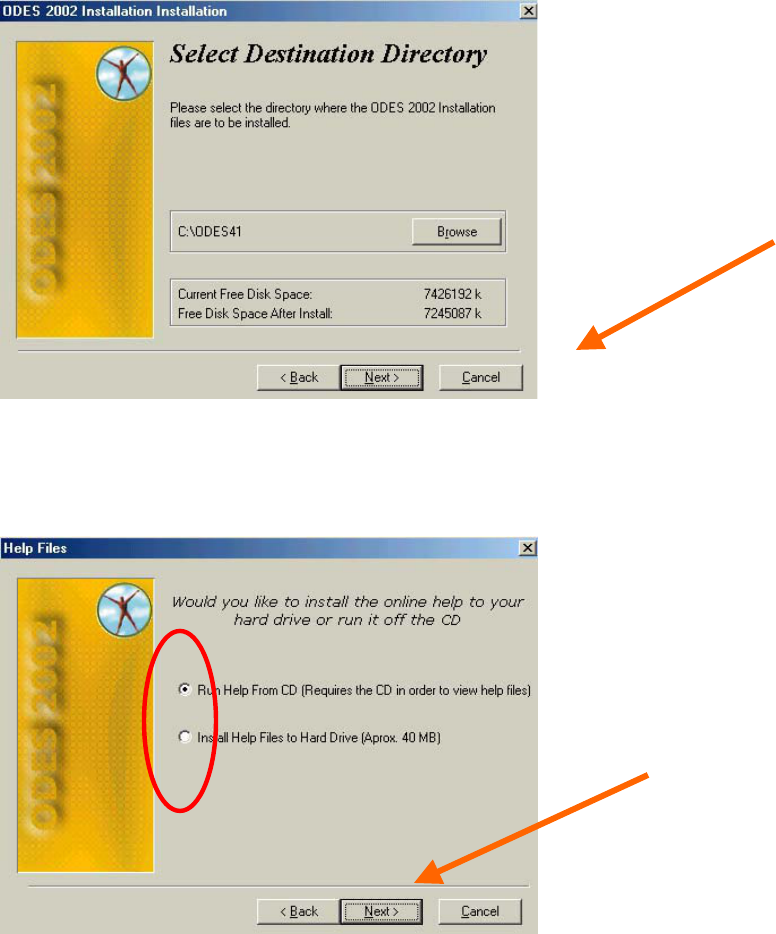
The next page allows you to select the directory on your hard drive into which ODES files will be installed.
For most installations, click Next. Click on Browse if you wish to install the ODES41 folder somewhere
other than the C-drive on your computer. If the indicated amount of free space that would be available
after installation is low or even below zero (most computers require at least 500,000K for normal
operation), Cancel the installation and create the necessary space on the drive you selected by removing
files, or uninstalling unused programs.
34
You may now choose to either Run Help From CD, or Install Help Files to Hard Drive. Generally, it is
recommended that you select Run Help From CD to save hard drive space on your computer. The help
files include a variety of manuals, marketing materials, and sample reports, which can help, get you
started. Once you have made your selection click Next.
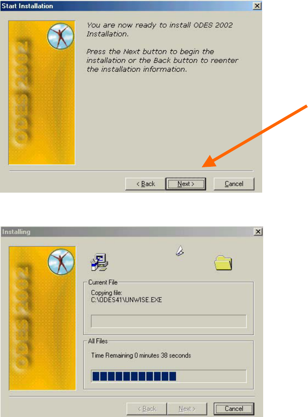
You are now ready to install ODES 2004 onto your hard drive. Click on Next.
35
A page will appear which shows you how the installation is progressing.
36
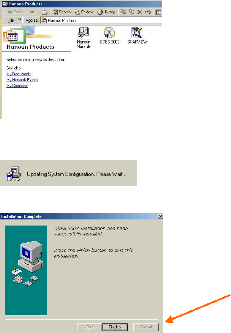
During this process, a window entitled Hanoun Products will open. You may close this window – ODES
will still continue installing in the background.
Once the installation process is complete, your system will update its system configurations. A pop-up
window will appear to notify you of this.
After updating its configurations, a window will appear notifying you that the installation has been
completed successfully. Click Finish.
37
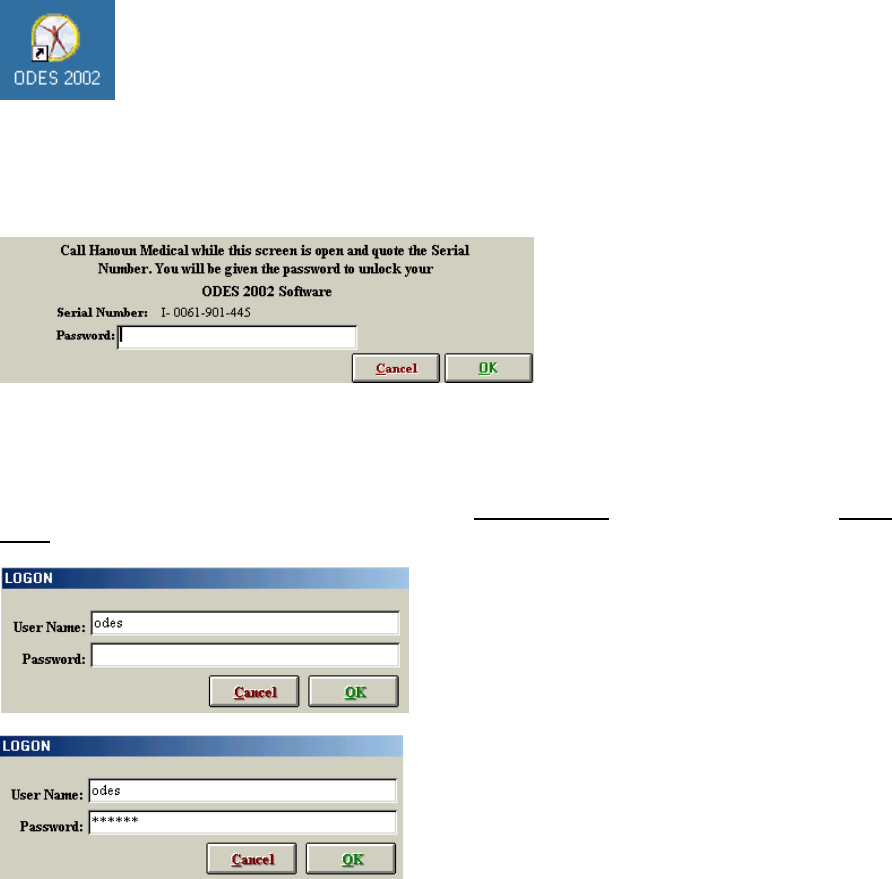
You will need to restart your computer before you can begin to use ODES. Click OK. Once your
computer has restarted, a new icon will appear on your desktop. To access ODES, simply double click on
the following icon:
You will now be required to register your software with the Customer Service Department at Hanoun
Medical Inc. A pop-up window will ask you to contact Hanoun Medical to receive your password. Call
(800) 461-6888 X2 and a Customer Service Representative will assist you.
Once you are successfully registered with Hanoun Medical Inc., you may begin to use our software.
Upon entering ODES, a log-in window will appear, prompting you for a password for the user name
“odes.” This password is always the same (“hanoun”), but can be modified through the Administration
Menu if you choose to do so later. The password is case sensitive and must be entered in lower
case.
38
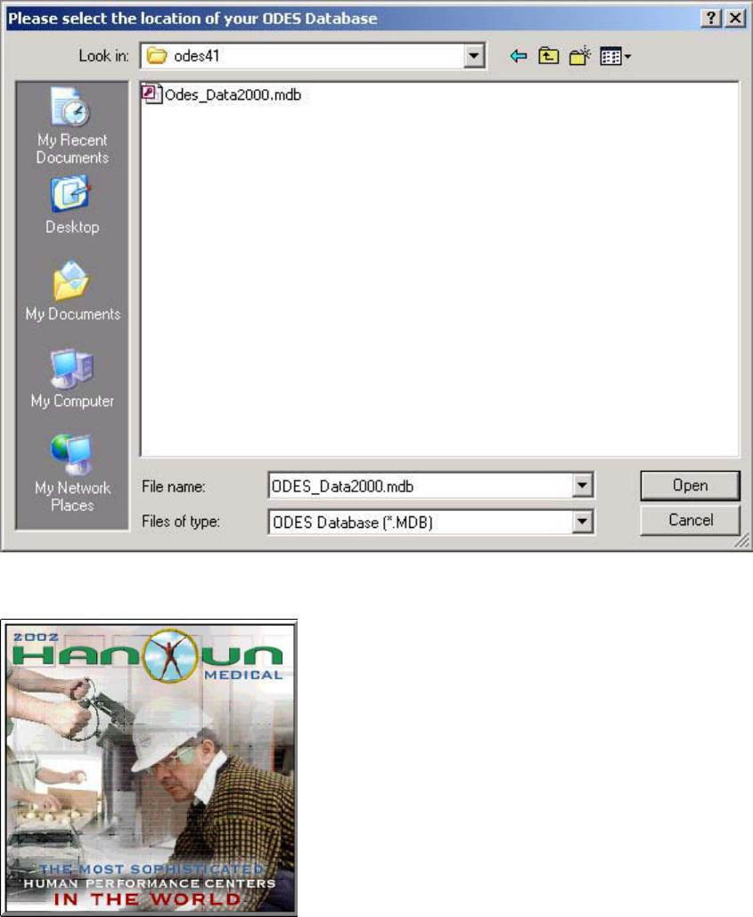
After the password (“hanoun”) has been entered, the program will launch. It will now ask you to confirm
the location of your ODES database, “Odes_Data2000.mdb”. Double click on this icon in order to
proceed.
The following introductory screen will now appear welcoming you to ODES.
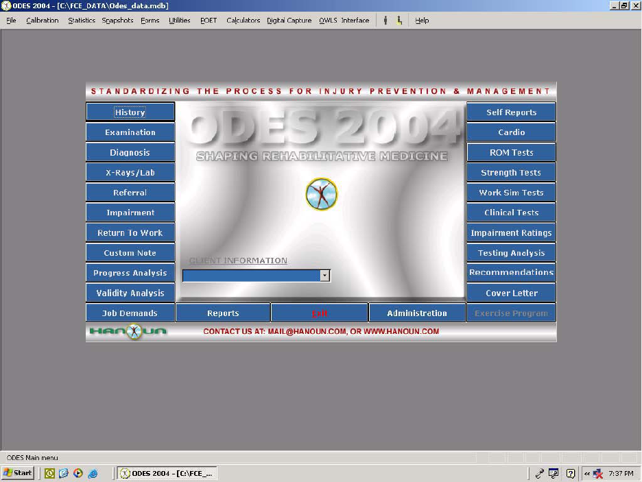
Once the program is initiated, the ODES main page will appear, which will allow you to access any
feature of the ODES software.
39
The next step is to set up and become familiar with the Administrative features of the software.
40
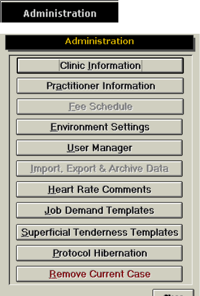
Administration Menu
Clinic Information
The ODES software allows an evaluator to store Clinic Information and Logos, in order to personalize
reports. ODES also has the ability to save multiple Clinic ID’s. To enter a clinic logo, double click on the
Clinic Logo blank field. Locate the saved logo file on your hard drive. The logo can be in any graphic file
format (.jpg, .gif etc.) and should be 8.1 cm x 2.0 cm, so that it doesn’t become distorted when attached to
a report.
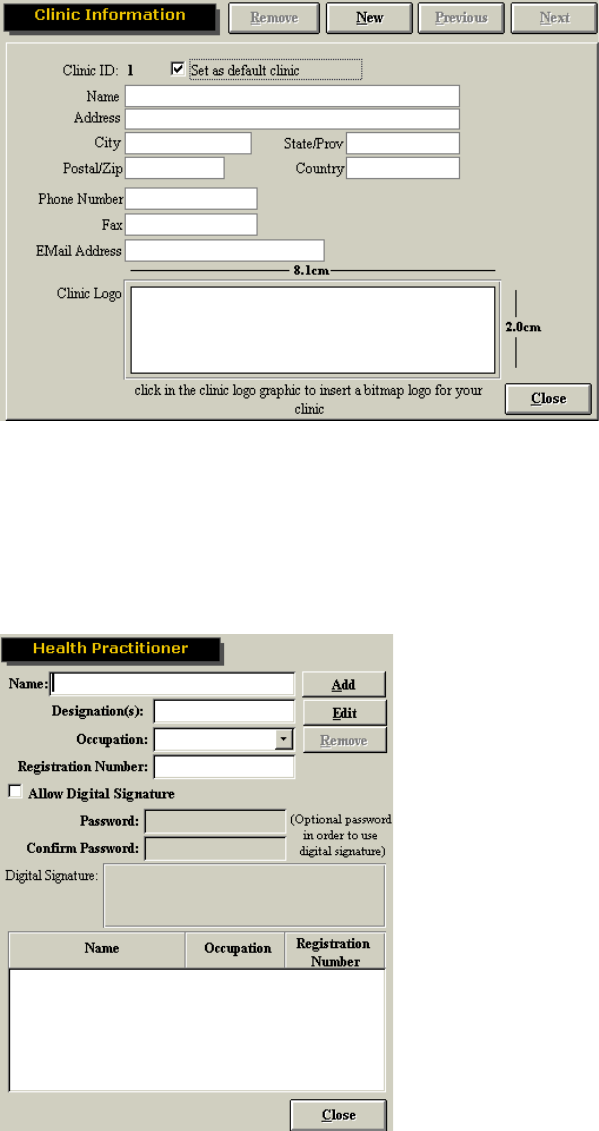
To add a new clinic location, click New. When printing a report, the name and logo for the default clinic
location will be included. To change the default location, click Next or Previous to select the correct
location and check the ‘Set as default clinic’ box.
41
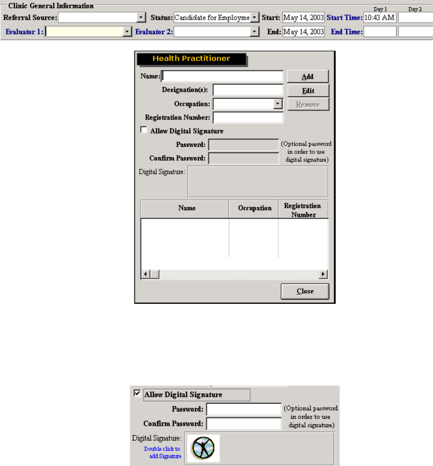
Practitioner Information
The ODES software allows an evaluator to store practitioner information and digital signatures, in order to
personalize reports. To add a practitioner, you must fill out the following fields: name, designation,
occupation, and registration number (if applicable). Then click Add to add the practitioner to the
database (the name will now appear at the bottom of the page).
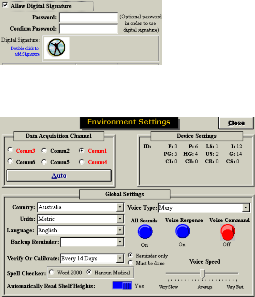
To add a digital signature, you must first scan the signature and save to your hard drive in a graphic file
format (.jpg, .gif etc.). Then, check the ’allow digital signature‘ box, create and confirm a password
(optional), and double click the Hanoun icon in order to locate the signature file on your hard drive and
associate the signature with the practitioner.
42
To edit the health practitioner information, highlight the name to edit from the list and click on Edit. Once
the changes have been made click on Add.
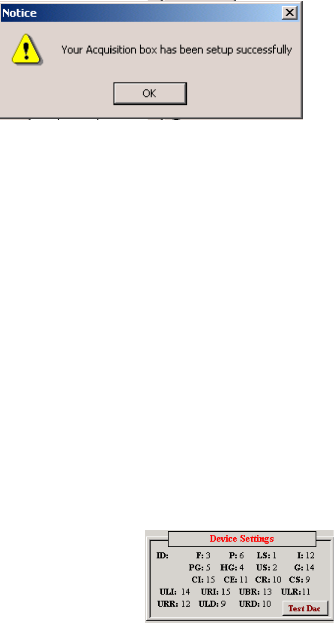
Environmental Settings
This page allows you to check communications between your Data Acquisition Box and your computer,
change device settings, alter your voices, modify calibration options and turn on or off shelf heights.
Clicking Auto will inform you whether the DAC Box is communicating with your computer or not. It is
recommended you do this before first attempting to calibrate your tools. If the DAC Box is not
communicating with your computer, refer to the Troubleshooting section of this manual.
43
The Device Settings section indicates which data acquisition box channel the various tools should be
plugged into, based on the set-up of the software. The following settings are used in normal set-ups:
F >> FOCUS Load Cell = 3
P >> Pressure Algometer = 6
LS >> Lower Shelf = 1
I >> Inclinometer = 12
PG >> Pinch Grip = 5
HG >> Hand Grip = 4
US >> Upper Shelf = 2
G >> Goniometer = 14 (12G on the Data Acquisition Box)
CI >> Cervical Isometric = 15 (Multi-Cervical System)
CE >> Cervical Flexion/Extension = 11 (Multi-Cervical System)
CR >> Cervical Rotation = 10 (Multi-Cervical System)
CS >> Cervical Seat = 9 (Multi-Cervical System)
ULI >> UTM Left Isometric = 14
URI >> UTM Right Isometric = 15
UBR >> UTM Bar Rotation = 13
ULR >> UTM Left Handle Rotation = 11
URR >> UTM Right Handle Rotation = 12
ULD >> UTM Left Handle Distance = 9
URD >> UTM Right Handle Distance = 10
Evaluator systems should change the F and P settings to 6 so that the algometer will not need to be
shifted between the two ports. The software looks for the Algometer in Port 6 for the Superficial
Tenderness Protocol, Fibromyalgia Protocol, and any new tests created under the strength or work
simulation section of the ODES software where the Algometer was chosen as the tool. The static muscle
strength tests and any pre-programmed work simulation tests (i.e. static push and pull) are looking for the
single FOCUS load cell, which is normally plugged into Port 3.
Evaluator system users should change their device settings in Administration Ň Environment Settings so
that both the FOCUS and Pressure Algometer settings are set to Port 6. This will prevent the Evaluator
from having to calibrate the Algometer in Port 6 and Port 3 (as the FOCUS). To do this open
Administration Ň Environment Settings and double click on the word Device Settings until it turns red.
44
Using your mouse click the number 3 beside ‘F’ until the number displayed is 6. Once you close the
Environment Settings page your settings will be saved. When you calibrate your equipment, you will
notice the button for the Algometer is missing and you will only be required to calibrate the Algometer as
the FOCUS.
The Global Settings section allows evaluators to specify the country they are in, and the units of
measurement to be used in printed reports. Currently the only available language reports may be printed
in is English.
The Backup Reminder should be set to 7 days for a stationary system, and 1 day for a portable system.
The backups should be saved on floppy disks (or, in the case of very large databases, a CD or ZIP disk)
and kept separate from your system in case of fire, theft or other equally damaging events.
The Verify or Calibrate Reminder should be set to 7 days. It is recommended that you calibrate your
Hanoun system once a week, and verify it before each day of testing. This will ensure your tools are
accurate in their measurement. The accuracy of your equipment is extremely important, particularly if your
report will be used in a litigious case. The Reminder can be set up as ‘Remind only’ or ‘Must Be Done’.
If you have Microsoft Office or Works Suite installed on your computer, you may wish to use the Word
Spell Check function on your reports. You also have the option of using the Hanoun Medical Spell
Checker, which is installed with ODES.
The ER and UE systems are the only Hanoun systems that automatically read shelf heights. All other
systems should have the Shelf Height switch set to ‘No’.
ODES features different voices (Mary, Mike and Sam) to provide variety for the evaluator, handle cultural
issues related to gender, and distinguish between computers in environments with multiple testing
stations.
The evaluator has the option of turning off All Sounds by clicking the left-most button. The center button
controls Voice Response, which refers to the computer’s announcements of the client’s name, shelf
heights for tests etc. Note that turning off Voice Response does not affect the computer’s ‘Start Test’
announcements, or count downs for rest periods. The Voice Command button is currently inactive at this
time. Voice Speed can also be changed by adjusting the dial beneath these buttons.
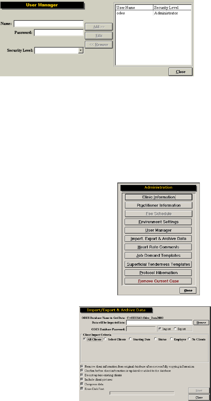
User Manager
You may add multiple users to the ODES software, with a variety of security levels. Enter a user’s name,
password and select a security level from the dropdown menu, then click Add. Available security levels
are:
x Administrator (Has full use of system);
x High (No access to User Manager);
x Medium High (All screens but User Manager and being able to remove cases);
x Medium (All screens but Administration);
x Low Medium (All screens but Administration and Reports. Also unable to remove assigned
protocols to a client or delete tests)
x Low (All screens but no access to client notes, Administration or Reports. Also unable to edit,
delete or create tests.)
x Lowest (Only access to client information and client case information)
45
To edit the users security level, highlight their name on the right hand side of the screen and click on Edit.
Once the changes have been made click on Add. To delete a user, highlight their name and click on
Remove.
Import and Exporting in ODES
The ODES software allows you to import and export data from one database to the other through the
import/export function. This feature is useful for those companies that have multiple evaluators who may
be providing services off-site or wish to complete reports at home. This allows the company to keep a
central database.
To access the Import/Export functions go to Administration/Import, Export & Archive
The following screen will appear
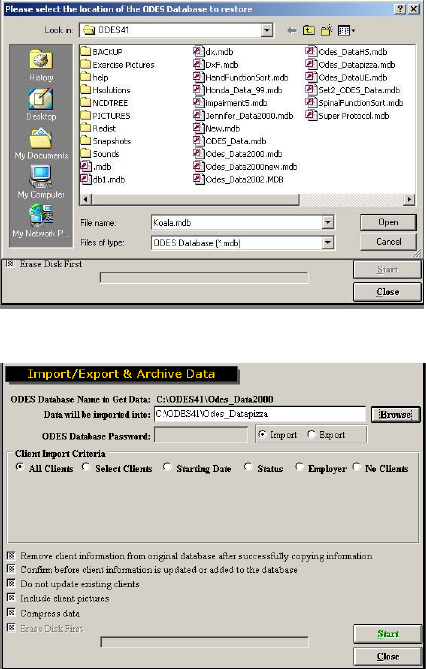
46
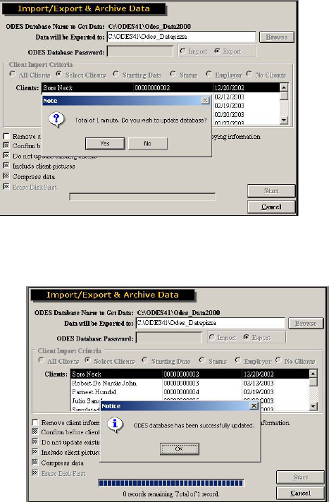
First select whether you would like to import to your current database or export data from your current
database to another one. To import or export data from another database, select import. Click on the
“Browse” button to locate the database you wish to import or export the data from.
Highlight the database you wish to import or export the data from and click on the “Open” button. The
database information will be now listed.
You will be required to include the ODES Database Password if you are importing/exporting from an
ODES database that is in a zipped format.
Select the Client Import Criteria from the selection provided:
x All Clients
oThis will import/export the clients as well as all new templates, custom tests, and super
protocols.
x Selected Clients
oA list of clients will appear and you will be required to highlight which ones you would like
to import/export. These clients will be imported/exported as well as all new templates,
custom tests, and super protocols.
x Starting Date
oA date from and to will need to be entered. This will import/export all the clients with the
starting date (which is outlined in case information) in these date ranges. It will also
import/export all new templates, custom tests, and super protocols.
x Status
oA list of the different status options will be available for you to choose from. Status is
selected for each client through case information. It will also import/export all new
templates, custom tests, and super protocols.
x Employer
47
oA list of employers will be provided for you to select from.
x No Clients
oThis selection will allow you to import/export all templates, custom tests, and super
protocols.
Next provide details on how you want this data handled:
x Remove client information from original database after successfully copying information
x Confirm before client information is updated to the database
x Do not update existing clients
x Include client pictures (from case information)
x Compress data (if you are saving it to a floppy or e-mailing the database afterwards)
x Erase Disk First (available only if you are exporting to a floppy drive)
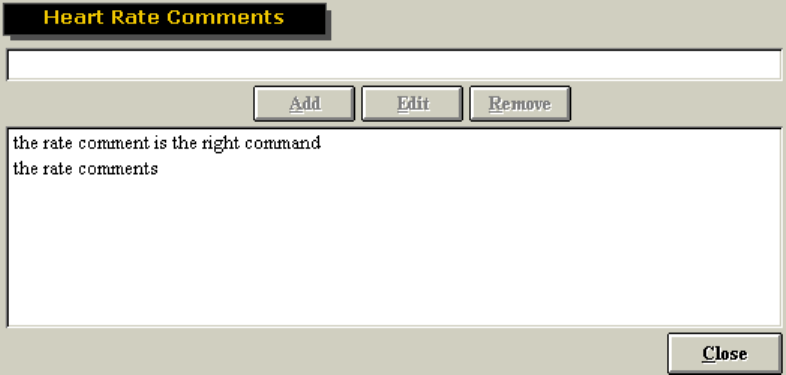
Once all the parameters are set up click on the “Start” button. A screen will come up to give you the time
to complete the task.
At the bottom of the screen a progress bar will give feedback on the progress of the update.
The software will indicate if it was success or not.
It is important to note that with importing and exporting the software will check the tests and if you have
made any changes to the standard tests (i.e. changed test or report descriptions or any other parameters)
it will considered this a new test and you will find duplicates of tests in your system. If this happens simply
put the duplicates under protocol hibernation or delete them, providing you are certain the one you are
48
deleting is the duplicate. Deleting tests means also deleting any test data in client’s files so be sure before
you delete.
It is recommended if you are going to be importing data obtained off-site to your main database that you
export the main database (no clients) to the local database you will be using. When you import the data
from your local database to the main database there will be no duplicates, as the software will recognize it
as the same database.
Heart Rate Comments
This feature allows you to save common heart rate comments for later use.
To add a comment, enter it in the blank field at the top of the screen and click Add. The comment will
then be listed on a dropdown menu when the heart rate is captured during testing. To edit a comment
highlight it, then edit the text as it appears in the top field and click Edit. To remove a comment, highlight
it and click Remove.
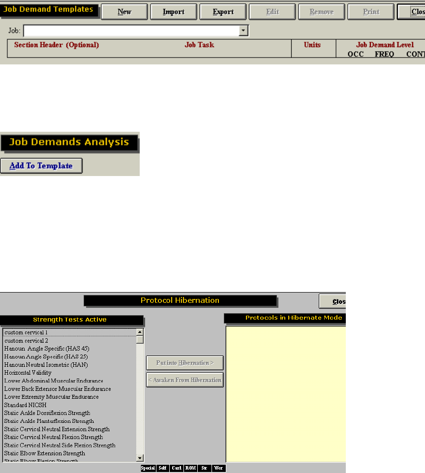
Job Demand Templates
From this page, you may add new Job Demand Templates, and import, export, edit or remove existing
templates from ODES.
To add a new Job Demand Template, click New. Enter the job title and source of the information (i.e. job
site analysis, Dictionary of Occupational Titles, self report etc.)
The Section Header is optional. If Section Headers are used however, the Job Demand Templates will be
grouped by Section Header (i.e. lifting, positional tolerance, mobility) when the templates are printed.
Include details on job tasks, units of measurement, and the job demand level (OCCasional – 1-33%;
FREQuent – 34-66%; CONstant – 67-100%). Click Save once you have added all the needed
information.
Job Demand Templates can be exported for use on another computer with ODES installed, or imported
from another computer with ODES. This reduces the need to re-enter data previously collected. To import
templates, click Import and select the location on the computer from which you will be receiving the
templates, and well as the location on your computer where the imported templates will be saved. You
49
must also indicate whether you will be importing all the templates in the source ODES database, or just
the current template.
Print the Job Demands Templates by clicking Print. The report can also be printed by clicking Export to
create the report as a Word document (if you have Microsoft Office installed on your computer), or by
creating a report Snapshot (see the Snapshot section of this manual).
To edit a Job Demand Template, select the job from the dropdown menu, click Edit and make any
required changes. To remove a Job Demand Template, select the job from the dropdown menu and click
Remove.
To use a Job Demands Template, from the Job Demands screen in ODES for a paryicular client, select
the job from the dropdown menu and click Populate. This will add the Header, job task, job demand level,
units and information source to the appropriate fields. Complete the Ability Demonstrated fields, and
determine whether there is a job match or not.
To add a Job Demand template from the Job Demands screen, click on Add to Template.
Protocol Hibernation
This feature allows you to place existing protocols, which you may not use often, into a separate folder
thereby allowing you to free space within the protocol pages. You can add and remove protocols from
this feature without losing data or deleting testing information. Protocol hibernation can also be accessed
through the protocol pages.
50
To hibernate a test, highlight the test on the left hand side of the screen and click on Put into
Hibernation. To bring a protocol back into the normal list of tests to slect, highlight the test from the right
hand side of the screen and click on Awaken FromHibernation.
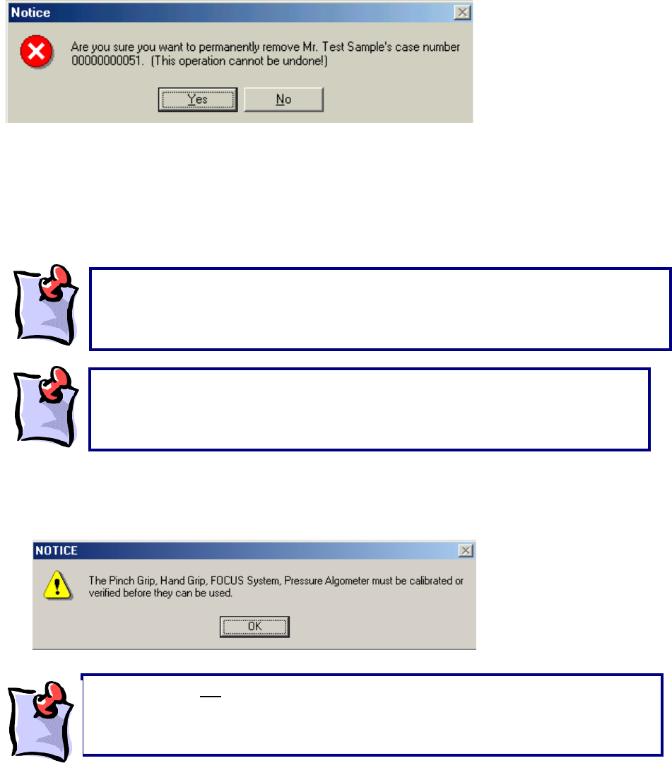
Remove Current Case
You may delete client cases by selecting the client/case that you would like to delete, and then clicking
Remove Current Case. This information cannot be retrieved. A warning will appear prior to deleting
data.
Calibrating the Equipment
Before you will be able to use your system you must calibrate and verify the equipment.
If the following message appears when ODES is launched, the pinch grip, hand grip, FOCUS System,
and Pressure Algometer must be calibrated or verified before testing. The message will alert you as to
which tools need to be calibrated.
It is important to note that calibration should be performed on a weekly basis and
verified daily . Prior to an assessment that may be challenged legally, both
calibration and verification of all devices being utilized for the assessment should be
performed.
Prior to calibrating any device, please ensure that the Data Acquisition Box has been set
up successfully and is communicating with your computer. You can check to see if this
is the case by going to Administration | Environment Settings from the ODES main
menu.
Please note that NO testing can be performed unless the equipment is calibrated and
verified. This is especially true if you select the Must be done option in Administration
ŇEnvironment Setting. No tests can be performed until the calibration is complete.
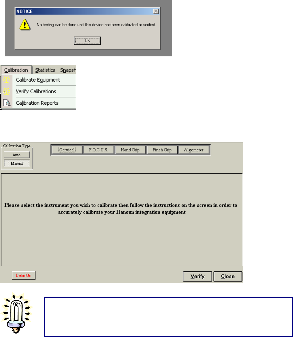
51
To calibrate your equipment, go to Calibration ~ Calibrate Equipment (If there is more than one type of
Hanoun system used with this database, go to Calibration ~ Calibrate FOCUS). Calibration should take
place once every week.
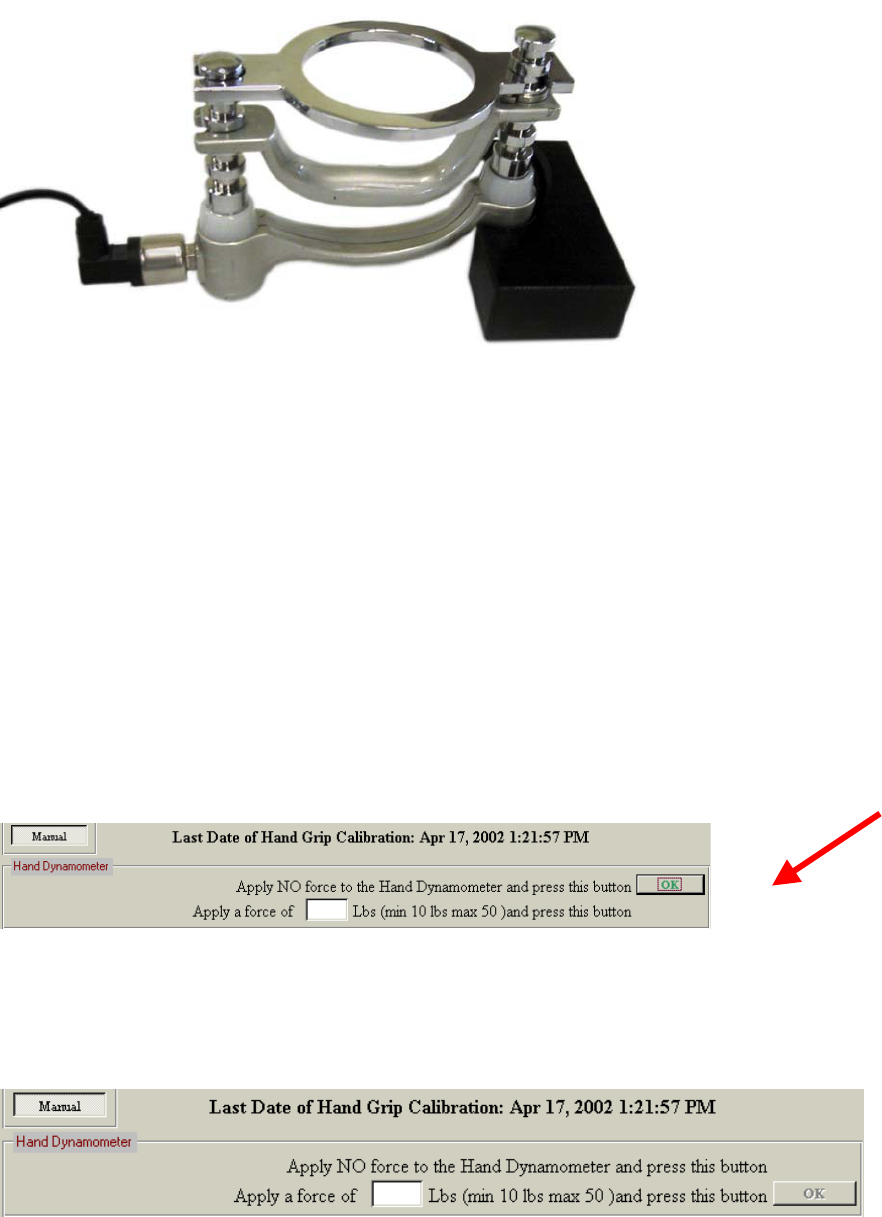
Calibration of the Hand Grip
Tips for Manual Calibration
Ensure that the weights are stable and do not wobble.
Ensure that the device is in a safe area away from the computer to prevent accidents
(i.e. – weight falling on the computer)
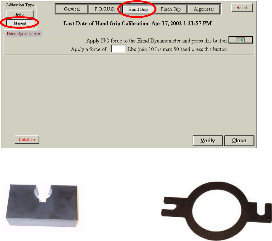
52
Please ensure that the Hand Grip is plugged into PORT 4 on the Data Acquisition Box.
After selecting the manual calibration option and the tool you wish to calibrate, the calibration page will
display as follows.
The above screen shows the last day of successful calibration (in this case it was April 17th), the type of
calibration and the directions involved in manual calibration. In order to calibrate, first locate the correct
attachment for the Hand Grip.
The first step in manual calibration of the Hand Grip is to place the tool in the square base
attachment.Click OK in order to zero the Hand Grip.
Next, attach the ring-shaped calibration tool to the rungs on the Hand Grip dynamometer (leave the hand
grip handle attached) while the tool is lying on its back. Notice that the attachment connects to the top
rung of the Hand Grip on one side and the second rung from the top on the other. This creates a flat
surface for weight to be placed upon. The calibration tool weight s 0.3 pounds.
53
To finish calibrating, locate a weight in order to complete this portion of the calibration process. Use a
minimal weight of 10 lbs in order to calibrate the device.
Enter the amount of weight you have chosen in the blank field. Make sure to add in the weight of the
calibration tool.
54
Once the weight is steady, click OK to begin the calibration. Do not hold the weight. It must be free
standing.
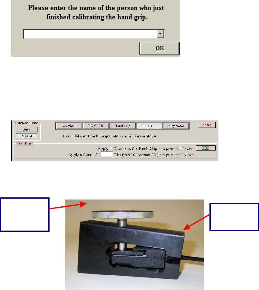
Once the device has been successfully calibrated, a page will be displayed requesting that the individual
who completed the calibration enter their name. This can be done either manually or, if your name exists
as a supervising practitioner in the database page, it will appear in the drop down menu.
Pinch Grip Calibration
Please ensure that the Pinch Grip is plugged into PORT 5 on the Data Acquisition Box.
After selecting the manual calibration option and the tool you wish to calibrate, the following page will
appear.
This page allows you to calibrate the Pinch Grip manually. It lists the last day of successful calibration (in
this case it was never done), the type of calibration and the directions involved in manual calibration. In
order to calibrate, you must first locate the correct attachments for the Pinch Grip.
The first step in manual calibration of the Pinch Grip is to place the Pinch Grip inside the calibration block
as above. Click OK to indicate that no force is being applied. Place the calibration tool through the block,
as above, and apply a minimum weight of 10 pounds.
Pinch Grip
Calibration
Tool = 0.3
pounds
Pinch Grip
Calibration
Block
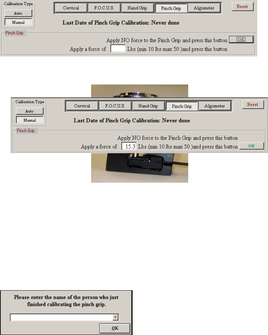
55
You should also note that the calibration tool for the Pinch Grip has a weight of 0.3 lbs. This weight must
be taken into consideration when calibrating the Pinch Grip.
Once the weight is steady, click OK to begin the calibration.
Once the device has been successfully calibrated, a window will appear requesting the name of the
individual who just completed the calibration. This can be done either manually or, if your name exists as
a supervising practitioner in the database, it will appear in the drop-down menu.
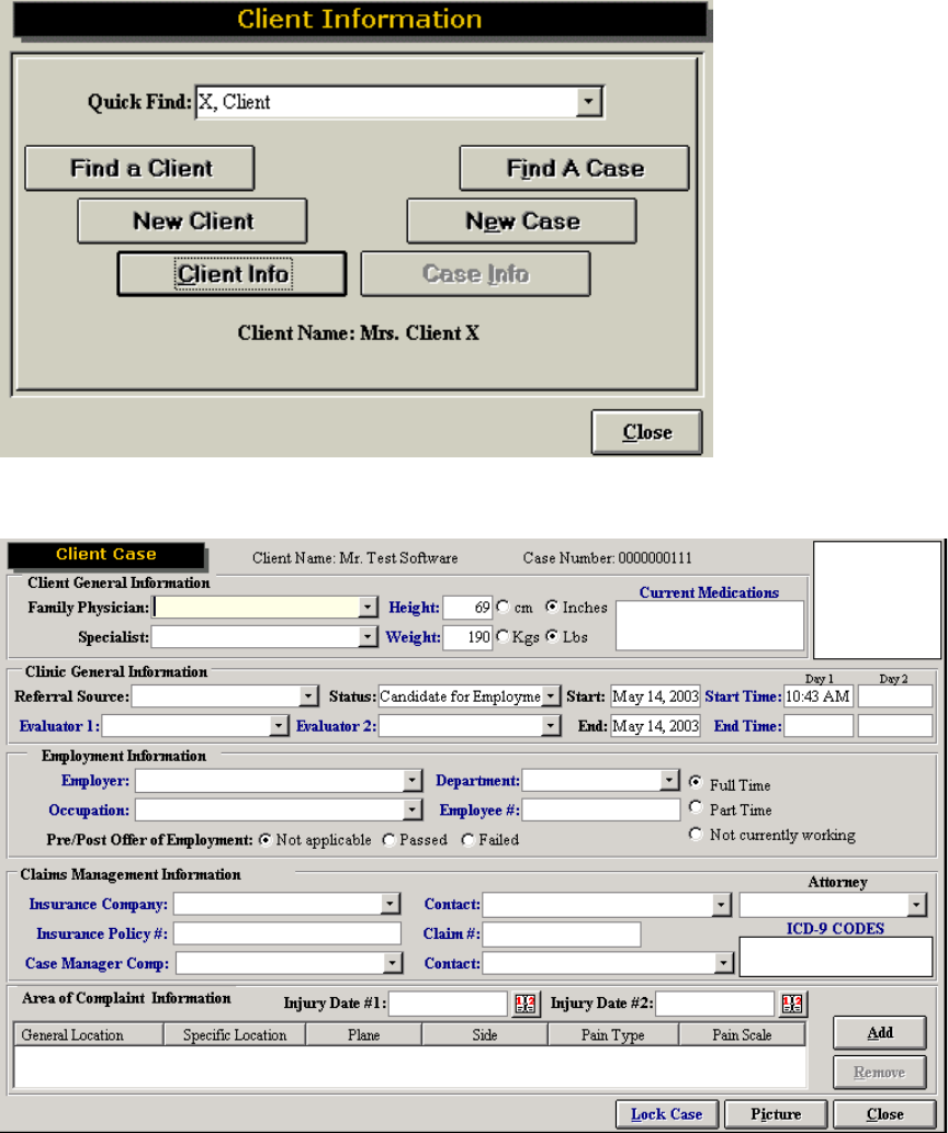
Algometer Calibration
Please ensure that the Algometer is plugged into PORT 6 on the Data Acquisition Box (unless you have
changed the device settings to Port 3. Refer to the algometer section for further details).
56
This page allows you to calibrate the Algometer manually. It indicates the last day of successful
calibration (in this case it was never done), the type of calibration and the directions involved in manual
calibration. In order to calibrate, you must first locate the correct attachments for the Algometer.
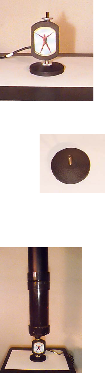
The following are the attachments necessary for manual calibration of the Algometer:
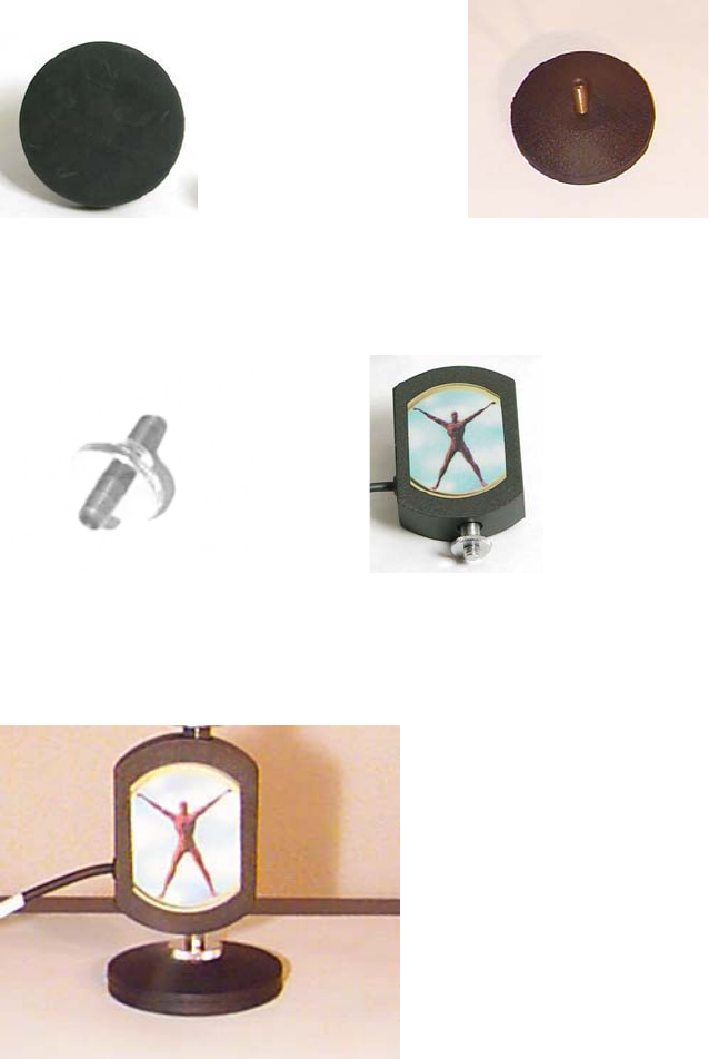
57
Flat Round Pad: Calibration Tool
Bolt: Algometer and bolt:
Attach the flat round pad to the base of the Algometer. Once attached, the Algometer can now stand on
this round pad.
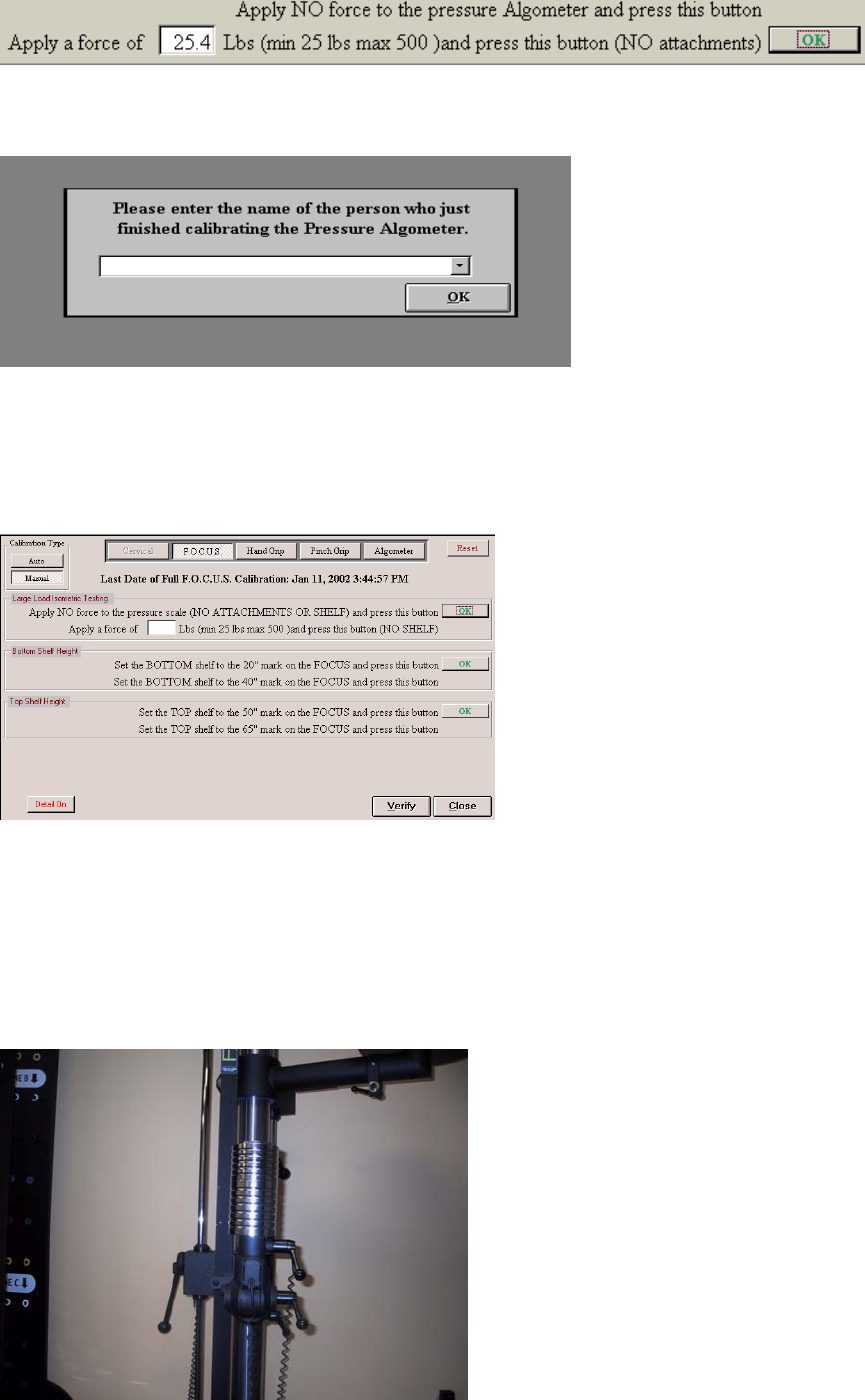
The extra bolt located with your attachments can now be added to the top of the Algometer Attach the
second calibration tool. Once the bolt is inserted and tightened you may click OK on the screen to signify
that no force is being applied to the Algometer.
58
You are now ready to attach the calibration tool in order to finish manually calibrating the Algometer:
Calibration Tool
The calibration tool (above) has a weight that needs to be taken into account. The Algometer calibration
tool weighs 0.3 pounds. Add this value to the total amount being applied to the tool. For example, the
Algometer requires that a minimum of 25 pounds be used. If you choose to calibrate with this weight plus
the calibration tool, the total amount of weight to enter in the blank field would be 25.3 lbs.
Place the weight being used on top of the attachment.
Once the weight is steady, click OK to complete calibration.
59
Once the device has been successfully calibrated, a screen will come up requesting the name of the
individual who just completed the calibration.
FOCUS Calibration
Please ensure that the FOCUS Load Cell is plugged into PORT 3 on the Data Acquisition Box.
To calibrate the accessory arm heights and the FOCUS Load Cell, select the “FOCUS” icon from the
main calibration page.
This page allows you to calibrate the FOCUS load cell and accessory arm heights manually. It indicates
the last day of successful calibration (in this case it was last done June 11, 2002), the type of calibration
and the directions involved in manual calibration.
Follow each step in progression and click the corresponding OK button.
Begin by attaching the Multiplanar Accessory Housing Joint. Ensure that no accessories are attached to
the Multiplanar Accessory Housing Joint.
When you calibrate the load cell, you must place your calibration weight on the Multiplanar Accessory
Housing Joint while no accessories are attached to it and it is positioned up.
Enter the amount of weight in the blank field on the FOCUS calibration page.
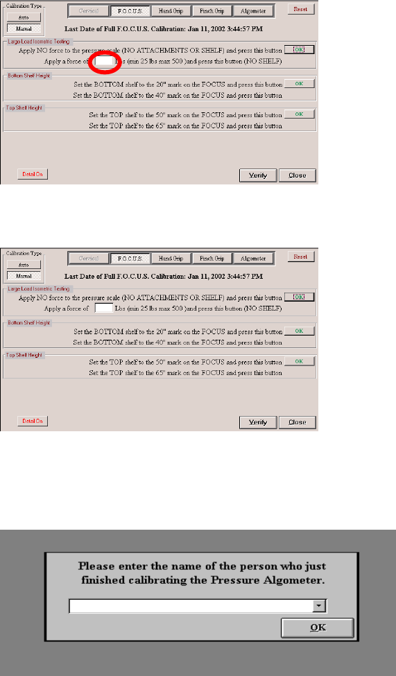
60
Click OK adjacent to the Load Cell Calibration instructions.
Each of the two ER accessory arms is calibrated separately.
Follow the instructions listed under “Bottom Shelf Height” or “Lower Accessory Arm” to calibrate the lower
accessory arm, then click OK.
Once the device has been successfully calibrated, a screen will come up requesting the name of the
individual who just completed the calibration.
Universal Task Master Calibration
Please ensure the Universal Task Master is plugged into TM on the Data Acquisition Box.
From the ODES main menu on the top menu bar, go to the Calibration | Calibrate Task Master.
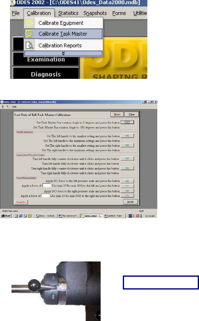
61
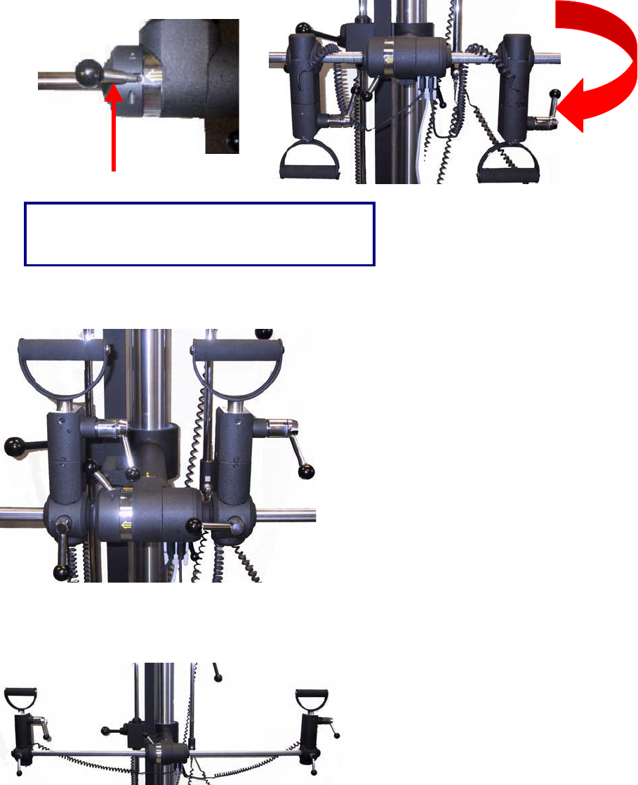
ODES will display a sequence of tasks for calibrating the UTM. The UTM rotation is to be calibrated first.
Follow the instructions on each line and click OK once the task has been performed. This moves the OK
button to the next instruction line.
Step #1: Set Bar Rotation Angle to Zero Degrees (Handles are closer to the ceiling)
Step #2 Set Bar Rotation Angle to 180 Degrees (Handles are closer to the floor)
View from to
p
of UTM.
62
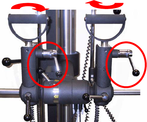
Step #3 and #5: Set the Left Handle to the smallest setting. The same picture illustrates the right handle
to the smallest setting.
Step #4 and #6: Set Left Handle to the largest setting. The same picture illustrates the right handle to the
largest setting.
Use this locking mechanism to rotate the bar. The
bar rotates forward and down.
63
Steps #7-#10: For supination/pronation: use the locking mechanism on the side of the load cells in order
to move the handles into either supination or pronation positions.
Remove the handles and click OK for NO force on the pressure scale.
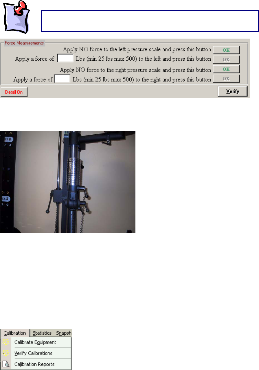
64
Enter the amount of weight that will be used to calibrate the left and right force scales in the appropriate
fields before you click OK. You must use a minimum of 25 pounds and for convenience use the same
weight for the right and left side. Calibrate one load cell, and then the other.
Once all of the tasks in the calibration have been completed, and no problems arose, the software will ask
you to enter the name of the individual who performed the calibration.
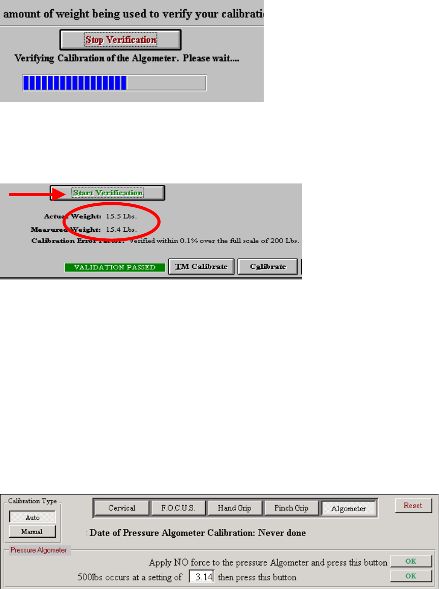
Weight Verification
After calibrating the tool through either automatic or manual calibration, it is recommended that the
accuracy of the device be verified. Verification should be completed prior to testing each day or after the
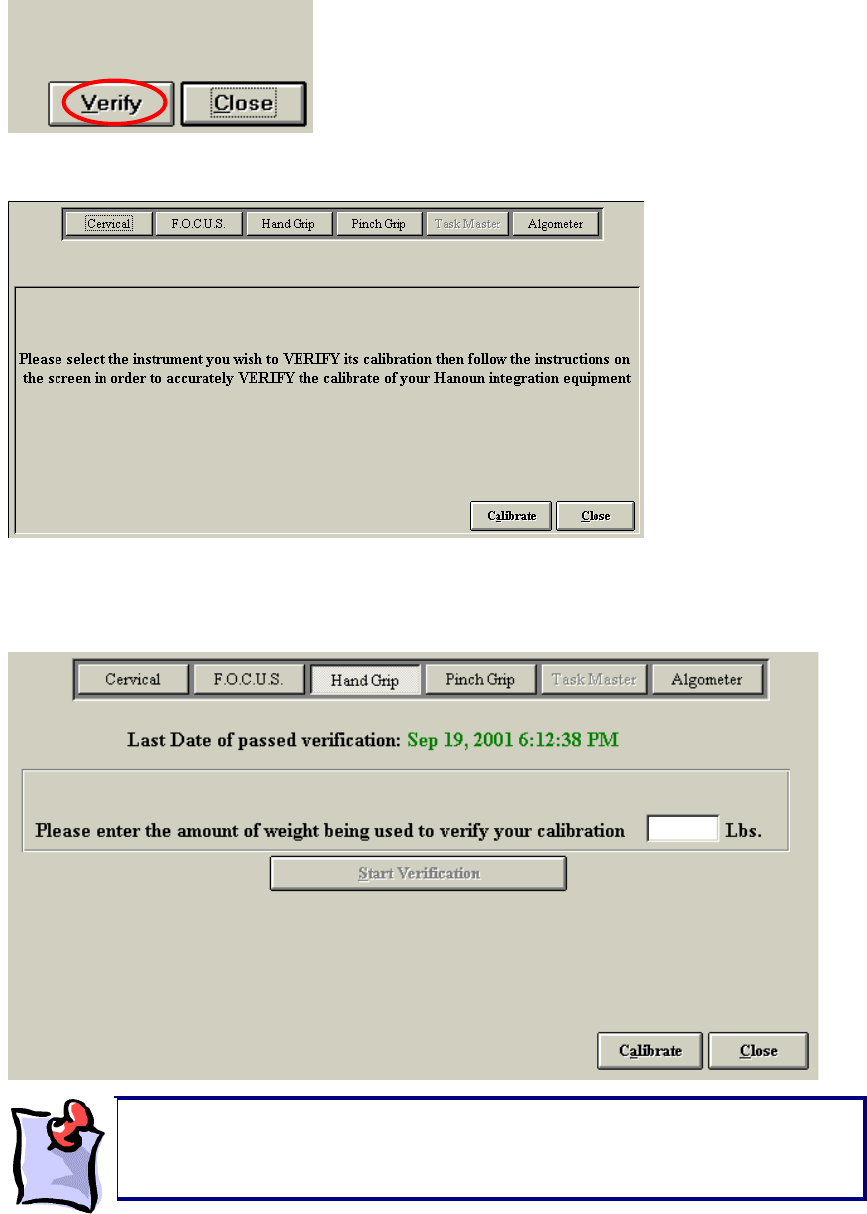
equipment has been set up. To verify go to Calibration | Verify Calibrations in the top task bar; or from
Verify in the bottom right-hand corner of the Calibration page, after calibration has been completed.
Just before calibration of the Force Measurements, shown in the screen below,
make sure to remove the left and right handles from the UTM.
65
Whichever method is used, the same page will appear:
From here, select the tool to be verified (in this case the Hand Grip) and you will be brought to the
verification page. This page allows you to select the equipment being verified, shows the most recent
date of passed verification and allows you to conduct the verification procedure.
The verification page on your computer will now ask you to enter the amount of weight you are using for
verification. A different weight should be used and entered into the blank field on the page. Make sure to
It is important to note that when verifying, a weight different than what was
utilized for calibration be selected. For example, if a 15 lb weight was used to
calibrate, use 10 lbs to verify.
66
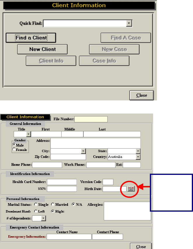
add in the value for the calibration tool if applicable. Set up the tool as you would for calibration. Click on
Start Verification to start the process.
Once the verification has taken place, the computer will notify you if the verification has been passed or
failed. Regardless of passing or failing the verification, the computer will provide you with the difference
between the actual and measured values. In order to be successful, the actual and measured values
need to be within 0.2% over the full scale of 500 lbs (FOCUS Load Cell, UTM or Algometer) or within
0.1% over the full scale of 200 lbs (Hand grip, Pinch grip).
If the tool does not verify, click on Start Verification again. If the tool still does not verify on the second
try, re-calibrate the tool.
Auto Calibration
For Evaluator and CIRES systems, auto calibration can be set up. A floppy disk will be provided with the
system for this purpose. Follow the instructions on the disk to install this feature. Depending on how the
system is utilized, auto calibration will be effective for up to 3 months. Following this time period, the
factory settings are no longer accurate and manual calibration should be done.
To auto calibrate, click Auto, then click the tool you wish to calibrate and follow the instructions. When
auto calibration is set up it will include the voltage reading based on the tool you selected. Once you have
completed calibration, a window will prompt you to enter your name. If your name has been entered
under Administration ~ Practitioner Information, you will be able to select it from the drop down menu.

67
Calibration Reports
To print or view the calibration and verification reports go to Calibration ~ Calibration Reports. Printed
reports include the following information:
x Name of person who performed calibration/verification
x Date when the calibration/verification occurred
x Actual weight, measured weight and deviation from accuracy of each device calibrated
You may specify the print range for this report.
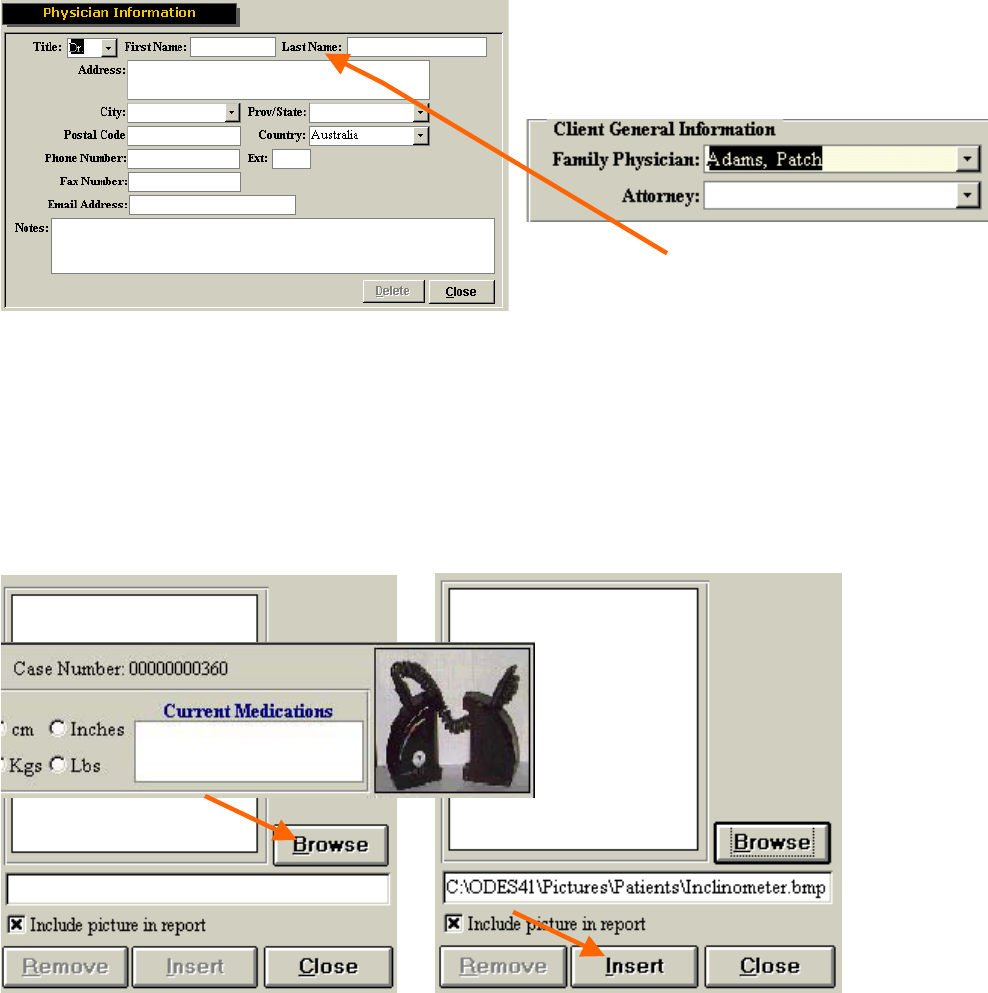
Adding a Client
In order to utilize the software, a client must first be entered. It is a good idea to create a sample client to
start with. To do so, simply double click on Client Information located in the center of the main screen of
ODES.
This will then take you to the Client Information page where you can find an existing client or case, or
create new clients or cases.
68
Click on New Client to create a new client file. Enter a client’s general information into the form.
Once all of the client’s general information is entered, click on Close, located in the bottom right hand
corner. The minimum information required includes name, gender, birth date (click on the calendar icon
to the right of the birth date to access a calendar) and dominant hand. This data is required for tests that
compare the client’s objective measurements with a normative database.
You will be returned to the client information page where you will now see the name of the newly entered
client.
This icon
allows you
to access a
calendar
69
Adding a Client Case
You will now need to create a new case for your client. Click on New Case.
Within the client case screen you can enter information regarding ICD-9 codes, referral source, family
physician, current medications, employer, insurance company, etc. Check in the drop down menu to see
if the contact has been added previously.
Adding in Family Physician/Specialist/Attorney/Referral Source/Insurance Company/Employer
To enter in a new contact, double click onthe white box. A new window will appear which will allow you to
add in contact information. The contact’s name will appear in the drop-down menu for that particular
contact type. This data will be saved in your database so the information will only have to be entered
once.
70
Client Photos
ODES has the ability to store and incorporate client photos into reports. After a picture has been taken
using a digital camera and saved to your hard drive, you may click on the large white box in the upper
right hand corner of the Client Case page, or click on Picture at the bottom right hand corner of the page.
This will allow you to find the client photo you wish to insert. Click on Browse and locate the picture
through Windows Explorer and then Insert the photo into ODES. The picture of the client will be seen in
the top right hand corner of the Client Case page (in this example a picture of the inclinometers) and on
the main screen of ODES.
71
Evaluator 1 and 2
The Evaluator 1 and 2 fields allow the evaluator(s) to enter their name and credentials into the Client
Case page. Check in the drop down menu to see if the evaluator’s name has already been entered. To
enter a new Evaluator, double click in desired field.
Enter in the Evaluator’s name, designation, occupation and registration number. This information will be
included in the front of the report, and beneath the signature sign-off line (if a signature is requested when
printing the report). Please note this is not a feature of all reports printed in ODES.
Click the Allow Digital Signature checkbox if you would like to add your signature to the software. This is a
useful tool if you are anticipating e-mailing reports.
Double click on the Hanoun logo and locate your scanned signature on your hard drive. The file must
have been saved as a bitmap (extension .bmp). A password can be added to this section to prevent
unauthorized use of the evaluator’s signature. To add a password, enter it in the Password field, and
again in the Confirm Password field. If you do not wish to add password protection, leave these fields
blank. Click on Close to return back to the client’s case information screen.
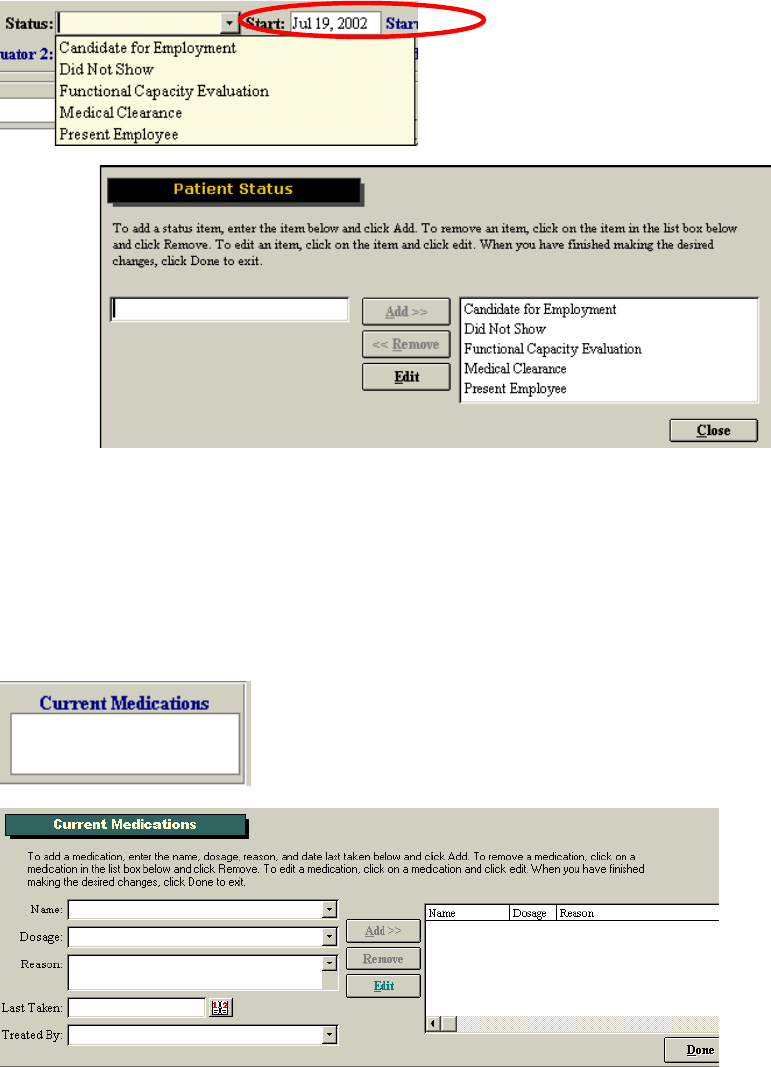
72
Client Status
The client status field is useful for keeping track of the number and type of assessments you have
completed. Client status can be used as a criterion under Statistical Queries. From the drop down menu a
number of selections are available. To add, edit or remove status information, double click on the blank
Status field. You may now add, remove or edit client status information. On the Client Case page this
information will be available in a drop-down menu.
Medications
A list of client medications can be added to the Client Case page by double clicking in the white box
below the Current Medications field. A new Current Medications window will appear. Enter the
medication information into the appropriate fields and click Add to associate medications with your client.
If the client is taking a medication that has previously been entered, select the name of the medication
from the drop-down menu and enter the remaining information by either typing it or selecting it from a
drop-down menu. Click Add in order to associate the medication with the client.
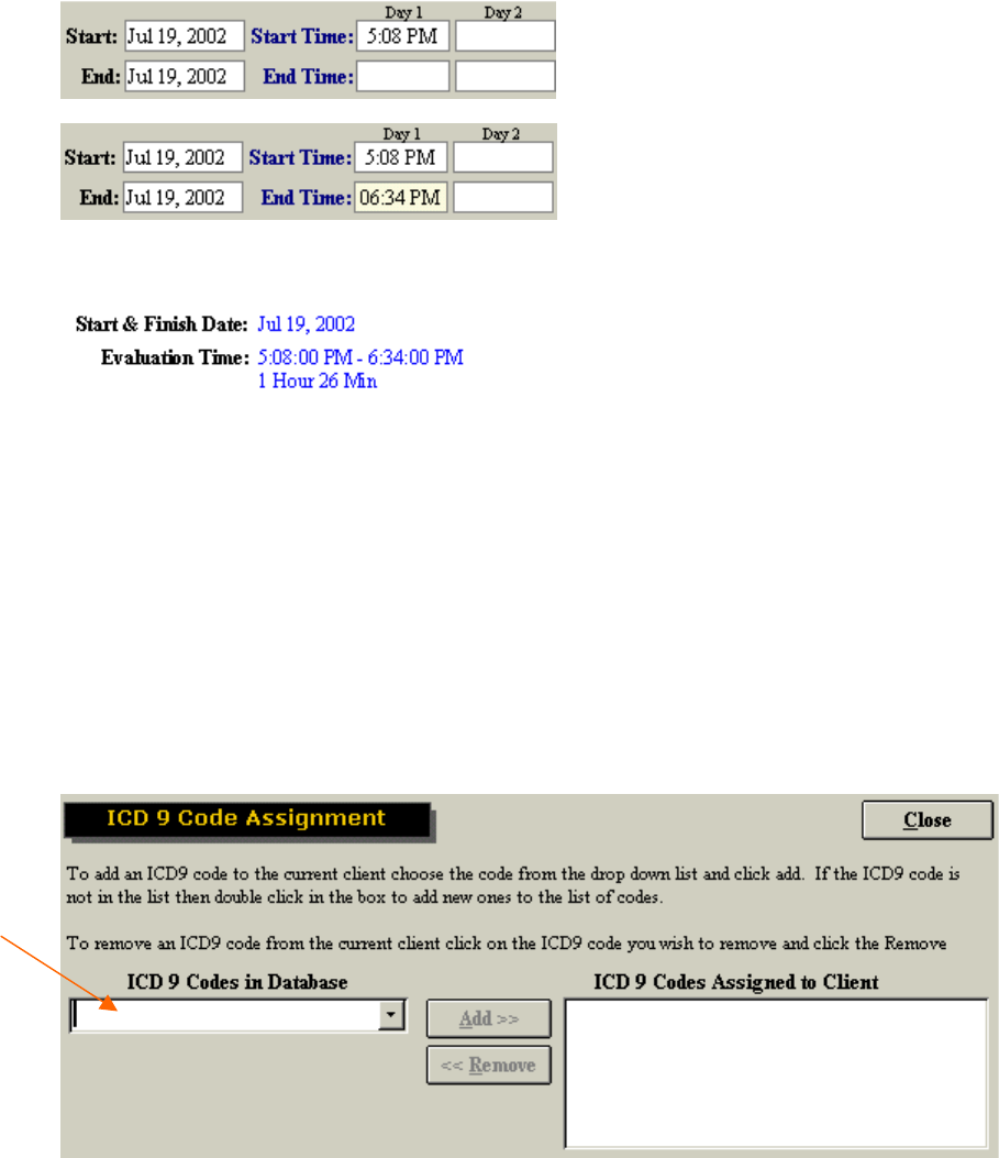
73
Start/End Time
The assessment start time and date are automatically logged on the Client Case page when you click on
New Case. In order to record an end time, simply double click in the corresponding blank field once the
assessment is completed. The current time will be entered into the field. You may also manually enter a
time.
Once this is done the evaluation time will be displayed on the cover sheet of your report.
Adding in ICD-9 Codes
ICD-9 codes can be stored within ODES for later use. Double click the blank ICD-9 Codes box on the
Client Case page. The ICD-9 Code Assignment window will appear. To add a new ICD-9 code, double
click on the ICD-9 Codes in Database field, add the code and description into the appropriate fields in the
Codes Edit window, then click Add. Once the ICD-9 code has been added to the database, it will be
saved and available from the drop-down menu for future clients. Once entered, the ICD-9 codes are also
available for use in the note templates.
To assign an existing ICD-9 code to your client, select the code from the Codes in Database drop-down
menu and click Add.
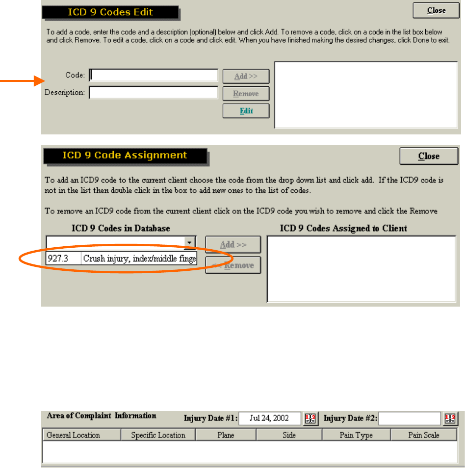
74
Areas of Complaint
A client’s areas of complaint may be obtained by having the client complete the Pain Diagram or the
Ransford Pain Diagram. To enter this information into the database, double click on the large Area of
Complaint Information box or click Add in the Area of Complaint Information section of the Client Case
page.
A pain diagram will be displayed, which will allow you to enter in location information and pain
descriptions.
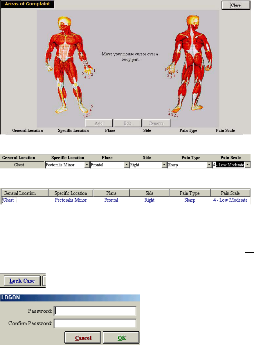
75
After clicking on the diagram location where the client presents a complaint, complete the chart below.
Once you have entered the information click Add, and it will appear on the Client Case page.
Locking Cases
This feature allows the evaluator to prevent other individuals from modifying a case. In order to utilize a
locked case, a password must be entered. Please note that it is your responsibility to remember this
password. If forgotten, our technical support/customer service staff at Hanoun Medical Inc. will not be
able to help you retrieve it. Click Lock Case at the bottom of the Client Case page and you will be
prompted to enter and confirm a password. Click OK when you are done.
Once locked, you will see the Lock Case button change to Unlock Case.
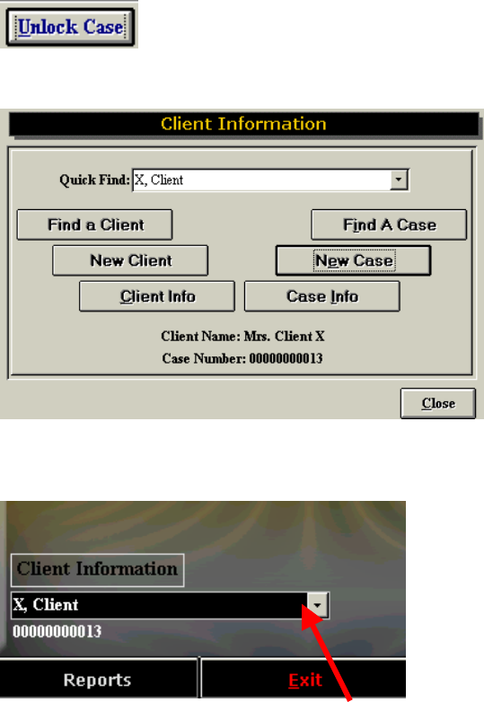
76
Once the Client Case page is completed, you may click the Close button located at the bottom right hand
corner of the page. This will bring you back to the Client Information page.
A case number will now be associated with your client. Click the Close button at the bottom right hand
corner of the page in order to return to the main menu.
Your client will now be listed in the drop-down menu underneath the Client Information button. To quickly
get into the client information screen, double click on the client’s name. To quicker access the client’s
case information, double click on the case number.
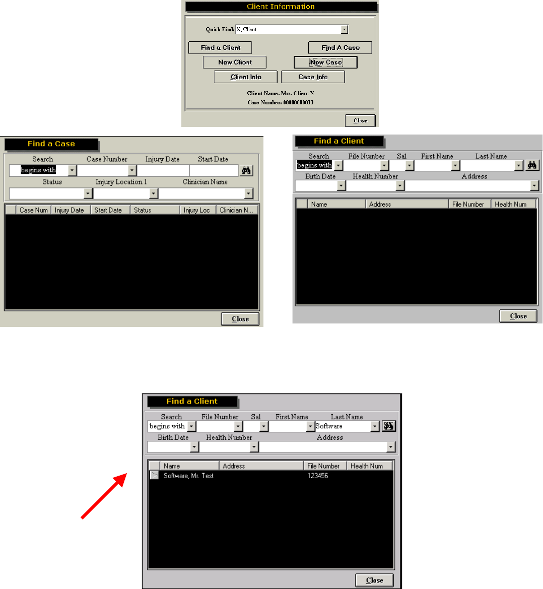
77
Finding a Client/Case
ODES allows you to search by client name or client case. Click on Find a Client or Find a Case to
access these options.
You may search using any of the fields. To see the search results, click the binoculars icon located at the
upper right hand corner of the page. Click on the arrow button to the left of the client’s name to open their
file.
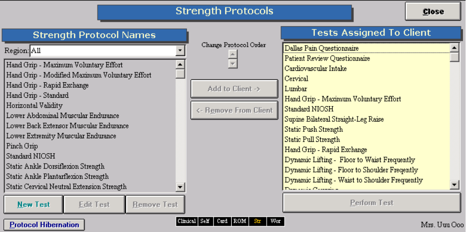
78
Adding a Test to a Client
Once you had added your client into ODES you can assign tests to the client. From the main screen of
ODES click on either Self Reports, Cardio, ROM Tests, Strength Tests, Work Sim Tests, or Clinical
Test. You can either highlight the test on the left hand side of the screen and click on Add to Client or
double click on the test on the left hand side of the screen and it will be automatically assigned to the
client. Once the test has been assigned to the client it will appear on the right hand side of the screen
under the heading Tests Assigned to Client. To change the order the tests will be completed in, highlight
the test on the left hand side of the screen and use the up and down arrows under the title Change
Protocol Order.
To perform the test assigned to a client, highlight the test on the right had side of the screen and click on
Perform Test or double click on the test on the left hand side of the screen and the test screen will open.
79
Removing a Test from a Client
To remove a test from a client, highlight the test on the left side of the screen and click on Remove From
Client.
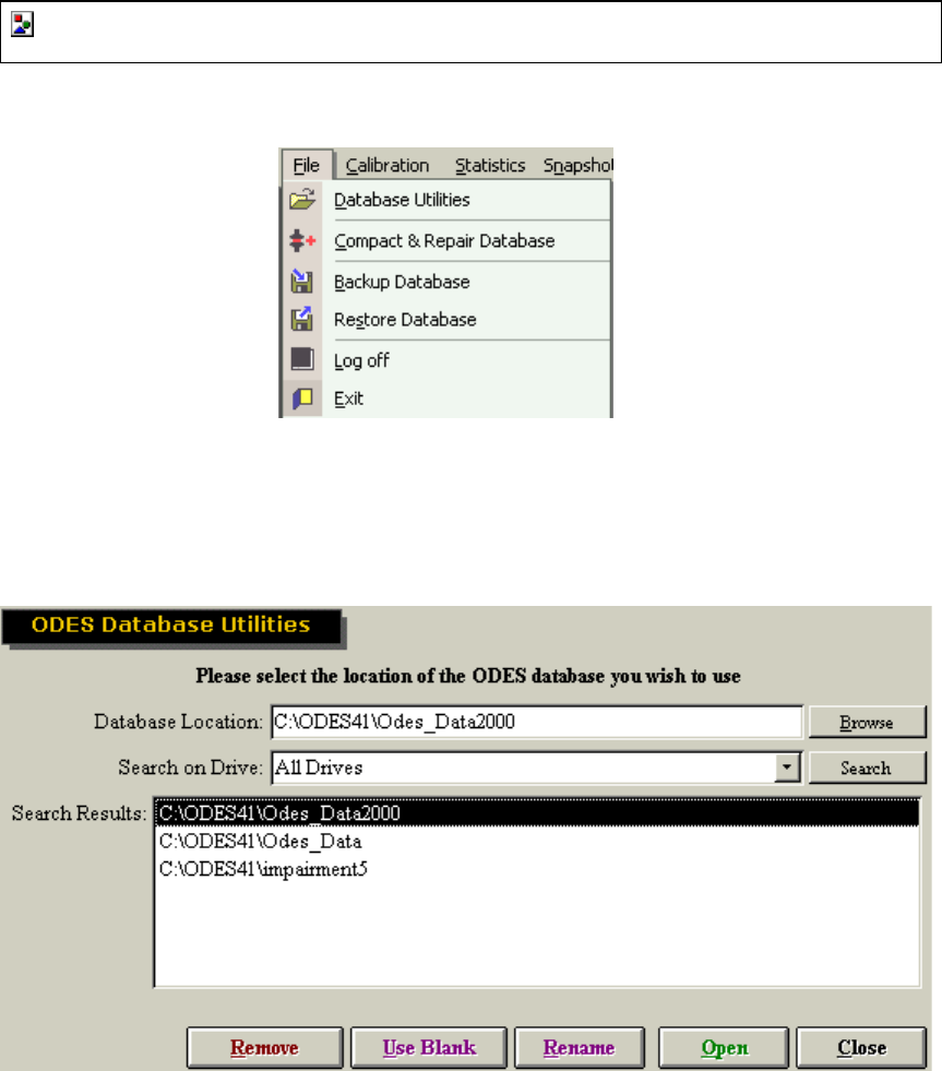
80
Additional ODES 2004 Software Features
Exploring The ODES Taskbar:
File Menu
Database Utilities
This function allows you to switch between active databases, create a new database or rename
an existing database.
To open an existing database, go to File ~ Database Utilities, locate the correct database in the
search results section, either by Browsing or Searching. To open the database, double click it so
that the name appears in Database Location, and then click Open. A window will appear asking
you to confirm that you have selected the correct database.
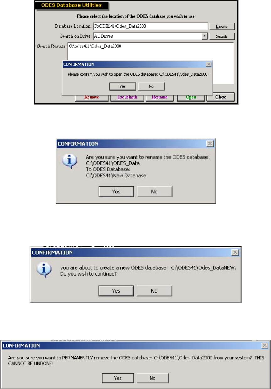
81
To rename a database, locate the database and double click it in the Search Results. The name
of the database will appear under Database Location. Change the name here, then click
Rename. The following window will appear to confirm the change.
To create a blank database, change the name of the database in the database location field.
This will be the name of your new database. Then, click Use Blank and confirm that this is the
database you wish to create.
If you choose to remove a database, it will not be recoverable by you or BTE Medical Inc. All
information will be eliminated. If you still wish to proceed, double click the database you wish to
remove and then click Remove. You will be asked to confirm this action.
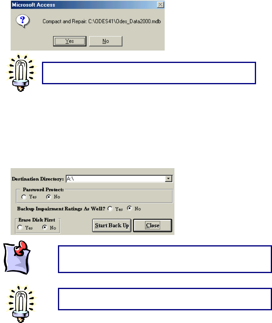
82
Compacting and Repairing A Database
This feature repairs any small errors that may occur due to networking. Go to File ~ Compact &
Repair Database to use this feature.
Backing Up Your Database
To back up your database go to File ~ Backup Database. This feature ensures that if your
computer is stolen or the hard drive fails you will be able to recover your client information and
testing data. We suggest backing up at the end of each day. This feature allows you to back up
all impairment ratings once selected, all client information and protocol information. This feature
will back up all client files. You may also associate a password with the back up – please note
that BTE cannot help you if the password is forgotten.
It is recommended you compact and repair your database every one to two
months.
A back-up reminder can be set in the Environmental Settings Menu to remind
you to perform this function.
It is recommended you back up your database to floppy disks at the end of
each day. If you are using a laptop or will be transporting your computer,
back up prior to moving the system.
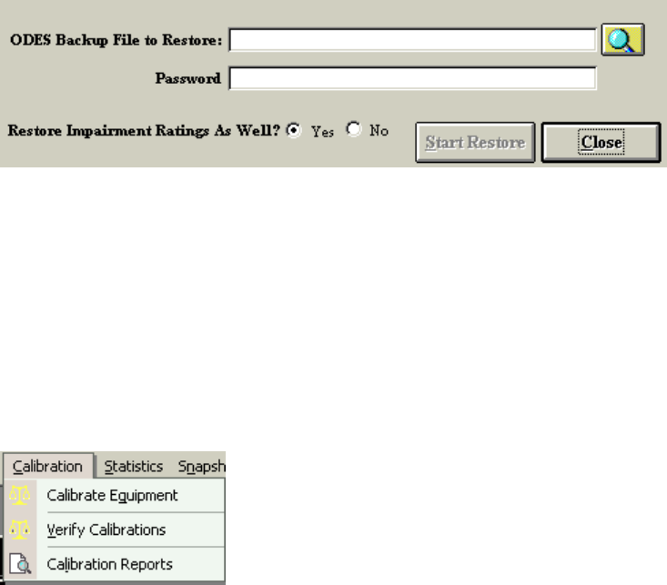
83
Restore Database
To restore a previously backed up database go to File ~ Restore Database. This feature allows
you to restore a database that has been backed up to a floppy disk or hard drive. It will replace
databases of the same name, however, so it is important to know what you are restoring before
you overwrite any information. After you restore a database, you must use the Database
Location field to find the newly restored database. Impairment ratings can be included in this
process. Passwords are only required if you indicated so at the time of data backup.
Log Off and Exit
The Log Off option is to be used if you are going to be using ODES on and off throughout the
day. By logging off rather than exiting, the speed of ODES will be enhanced. To exit the software
either click on exit from this menu, click on Exit from the main screen of ODES or click on the “x”
at the top right hand corner of the screen.
Calibration Menu
For calibration of each tool, please see the Getting Started section of the manual.
Calibrate Equipment
To calibrate your equipment, go to Calibration ~ Calibrate Equipment (If there is more than one
type of BTE system used with this database, go to Calibration ~ Calibrate FOCUS). Calibration
should take place once every week.
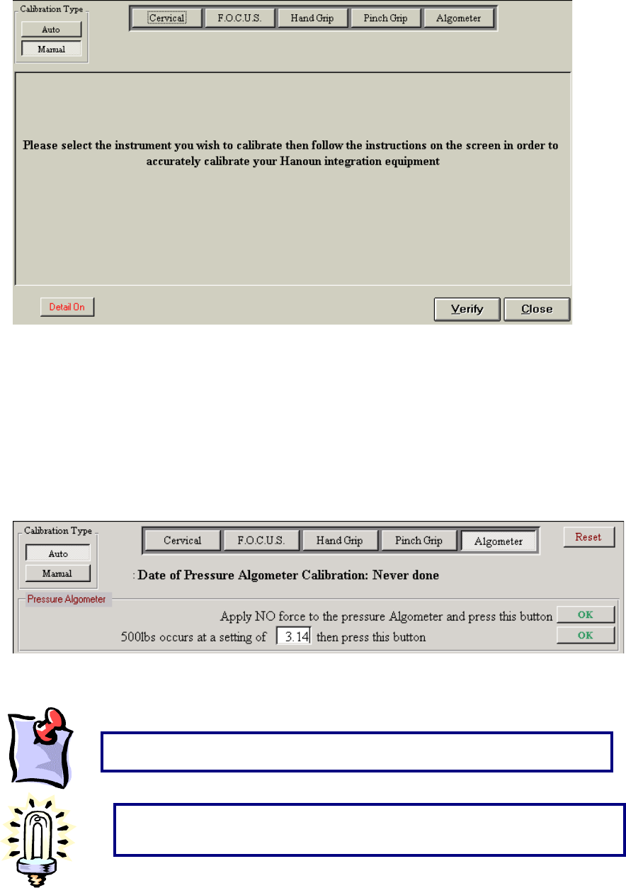
84
For Evaluator and CIRES systems, auto calibration can be set up. A floppy disk will be provided
with the system for this purpose. Follow the instructions on the disk to install this feature.
Depending on how the system is utilized, auto calibration will last up to 3 months. Following this
time period, the factory settings are no longer accurate and manual calibration should be done.
To auto calibrate, click Auto, then click the tool you wish to calibrate and follow the instructions.
When auto calibration is performed it will include the voltage reading based on the tools you
selected. Once you have completed calibration, a window will prompt you to enter your name. If
your name has been entered under Administration ~ Practitioner Information, you will be able to
select it from the drop down menu.
For all other systems, manual calibration is always used. Click Manual, select the tool you would
like to calibrate, and follow the instructions.
It is recommended you calibrate your system once a week.
A reminder to calibrate may be set through Administration
~
Environment
Settings.
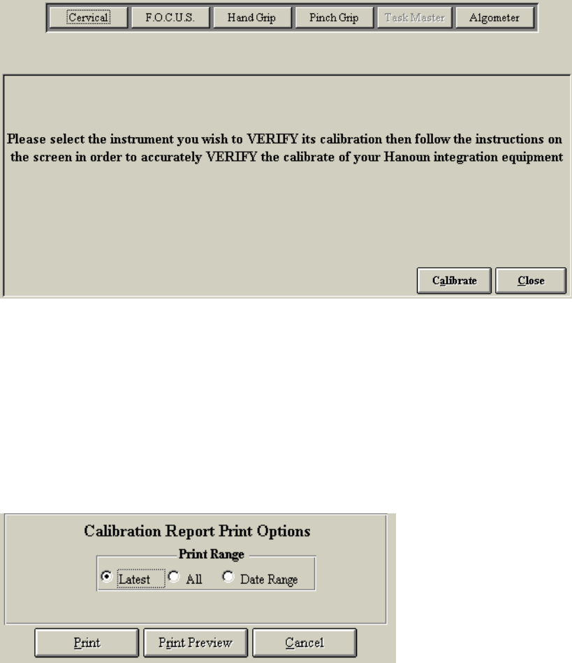
85
Verifying Calibration
To verify your calibrations, go to Calibration ~ Verify Calibrations (If there is more than one type
of BTE system used with this database go to Calibration ~ Verify FOCUS). Verification should
take place at the beginning of each day in order to make sure that the results are accurate. Click
the tool you wish to verify and follow the instructions. Once you have completed verification, a
window will prompt you to enter your name. If your name has been entered under Administration
~ Practitioner Information, you will be able to select it from the drop down menu.
Calibration Reports
To print or view the calibration and verification reports go to Calibration ~ Calibration Reports.
Printed reports include the following information:
Name of person who performed calibration/verification
Date when the calibration/verification occurred
Actual weight, measured weight and deviation from accuracy of each device calibrated
You may specify the print range for this data.
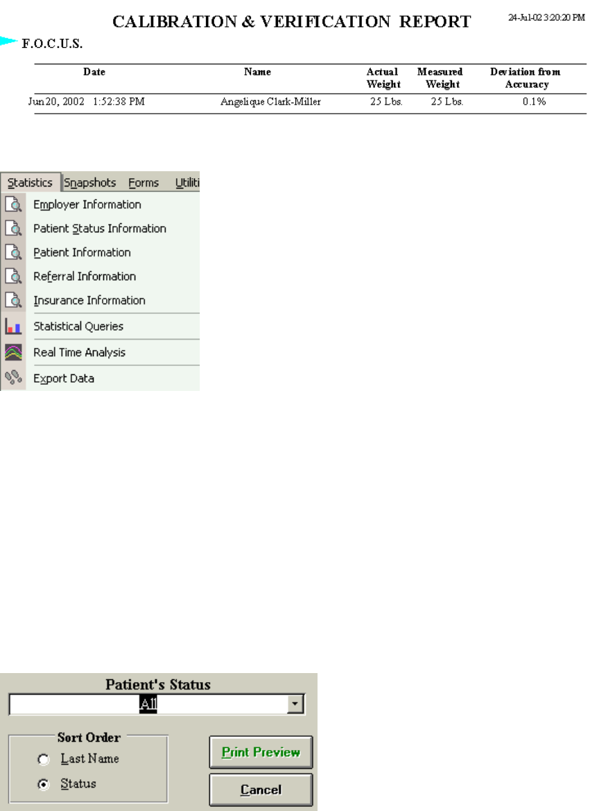
86
Statistics Menu
Employer information
Statistics ~ Employer Information provides a summary of all Employers that are stored within the
Case Information section of the ODES database. The report can be printed, exported to a
snapshot file format or exported to Microsoft Word (if Word is installed on the computer).
Client Status Information
Statistics ~ Client Status Information provides a summary of all Client Statuses. If the status of a
client has been added to the database in the Client Case page, the client will be added to this
report. You may sort by last name or by the status of the client. The report can be printed,
exported to a snapshot file format or exported to Microsoft Word (if Word is installed on the
computer).
Client Information
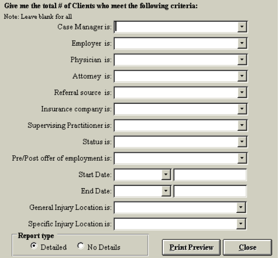
87
Statistics ~ Client Information provides a summary of all client information that has been added to
the database. The report can be printed, exported to a snapshot file format or exported to
Microsoft Word (if Word is installed on the computer).
Referral Information
Statistics ~ Referral Information provides a summary of all referral sources that have been
entered into the database. The report can be printed, exported to a snapshot file format or
exported to Microsoft Word (if Word is installed on the computer).
Insurance Information
Statistics ~ Insurance Information provides a summary of all insurance companies that have been
entered into the database. The report can be printed, exported to a snapshot file format or
exported to Microsoft Word (if Word is installed on the computer).
Statistical Queries
This function is located under Statistics ~ Statistical Queries. The ODES software allows its users
to query for information regarding existing clients in each of the following headings:
Case Manager Insurance Company
Employer Supervising Practitioner
Physician Status
Attorney Pre/Post Offer of Employment
Referral Source Start and End Dates
Insurance Company Injury Locations
This provides detailed information on length of treatment, common injuries and the number of
clients being referred from a specific source.
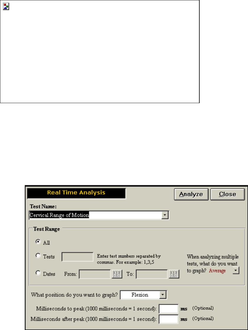
88
Under report type, select Detailed to obtain a list of the clients, and select No Details to obtain the
summary without client names.
You may also choose multiple criteria to make your search more specific. The report can be
printed, exported to a snapshot file format or exported to Microsoft Word (if Word is installed on
the computer).
Real Time Analysis
Real Time Analysis is accessed by going to Statistics ~ Real Time Analysis. It allows you to
analyze the data from each individual client in detail. It also allows you to compare individual or
multiple trials of any strength test recorded in the database.
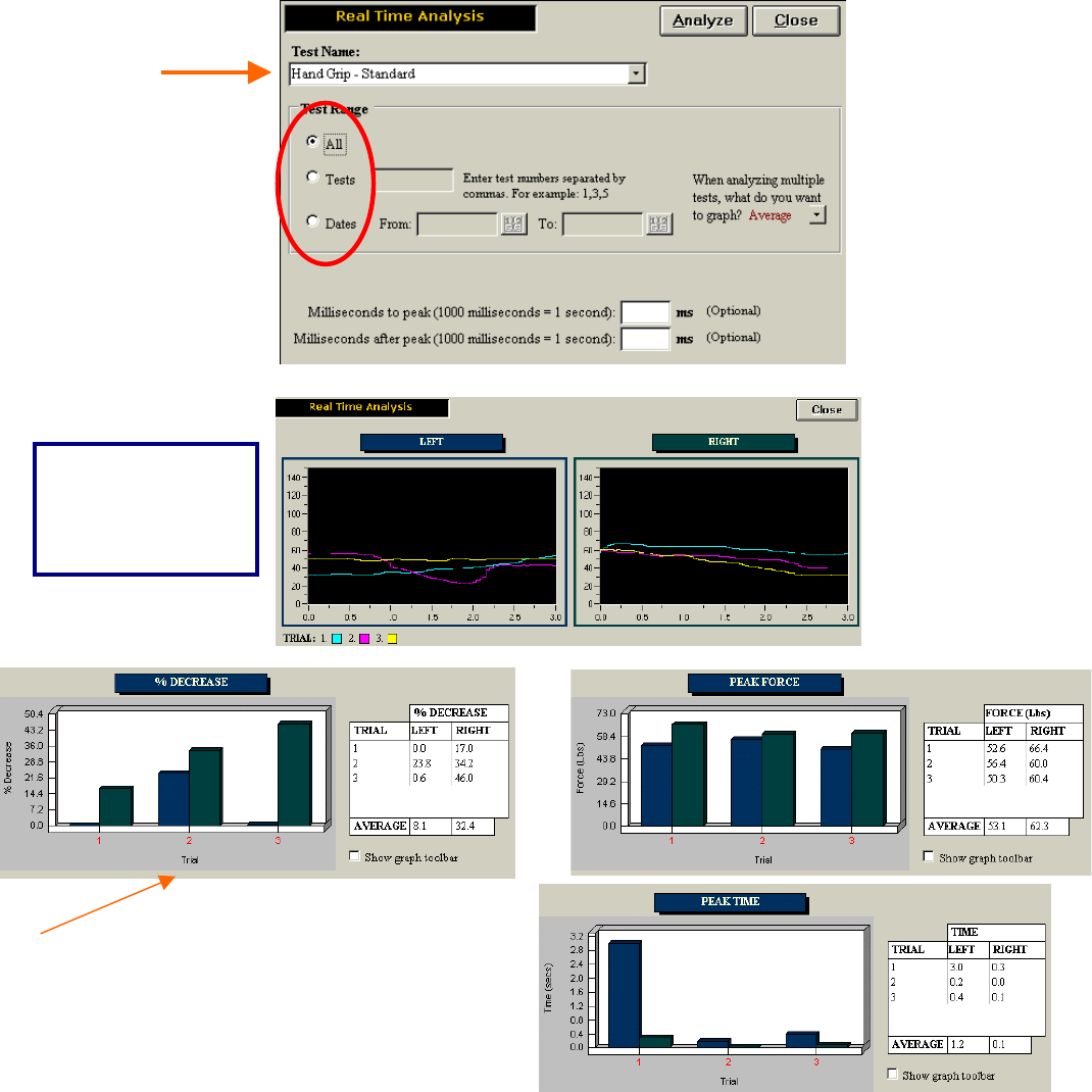
89
Real Time Analysis is a useful function for:
Research
Job Demands – You can see whether your client was able to obtain their required goal and
whether or not they were able to sustain it over time (i.e. their percentage of decrease after peak
value was obtained)
Client Progress/Tracking
Using Real Time Analysis
In order to utilize the Real Time Analysis feature, select the protocol to analyze.You must specify
whether you wish to analyze only one trial or all of the trials relating to a specific protocol in a
specific client. You may also analyze the selected protocol within a certain time frame.
The top graph
depicts the actual
values obtained in
the trials or test
selected
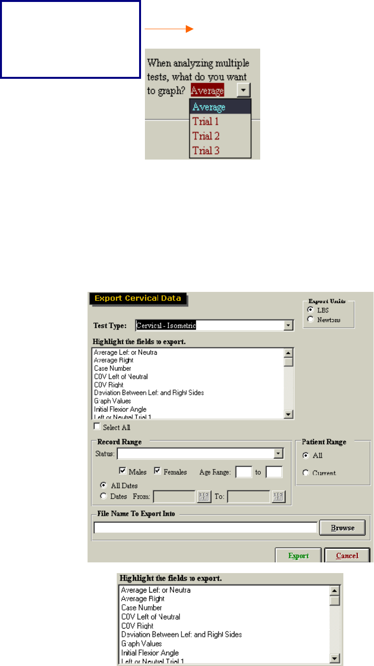
90
When analyzing multiple tests, you can choose to graph trial 1, trial 2, trial 3 or the average
values.
Exporting Data
ODES also allows its Multi-Cervical Users participating in International research with the
Melbourne Protocol to export raw data into a program outside of ODES. This allows you to work
with the data in a spreadsheet format if so desired. ER Users may also use this function, but are
limited to exporting only NDI data.
You may select individual or multiple fields to export from ODES, depending on the specificity of
your needs. You may isolate the data to be exported by Client Range, Units of Measurement,
Status, Gender, Age Range, and/or Date
Peak Force, Peak Time and
% Decrease are then used
to analyze your data. You
may also isolate your data
in milliseconds to peak and
milliseconds from peak
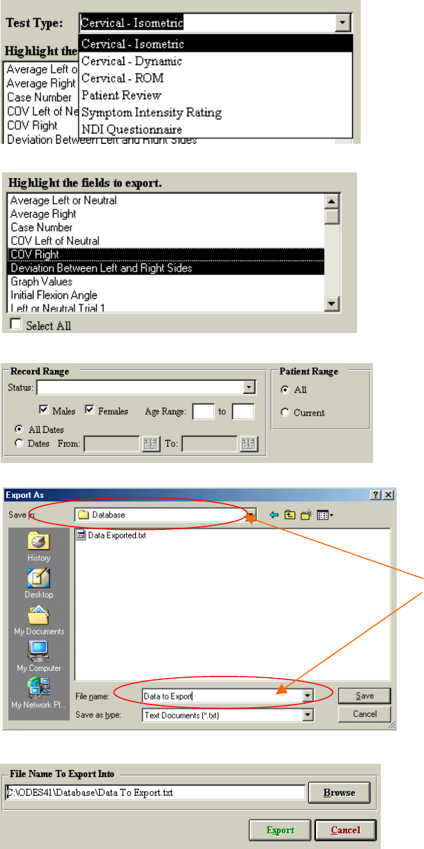
91
Using The Export Function
Select the type of testing
data you wish to export
Select the fields you wish
to include when exporting
Specify your target
population or target dates
Select a file name and a
directory – your data will
be saved as a text file
here.
The file name that you
chose will now be
written in the File Name
to Export line

92
Once the data has been successfully
exported, this message appears
Locating Your Exported Data
In order to locate the data that you just exported from ODES, you must first close the ODES
software and return to your Windows desktop.
Open the program that youexported the data to (i.e. Excel)
Go to the Data tab, select Import External Data ~ Import Data
Find your text file – open it and follow directions
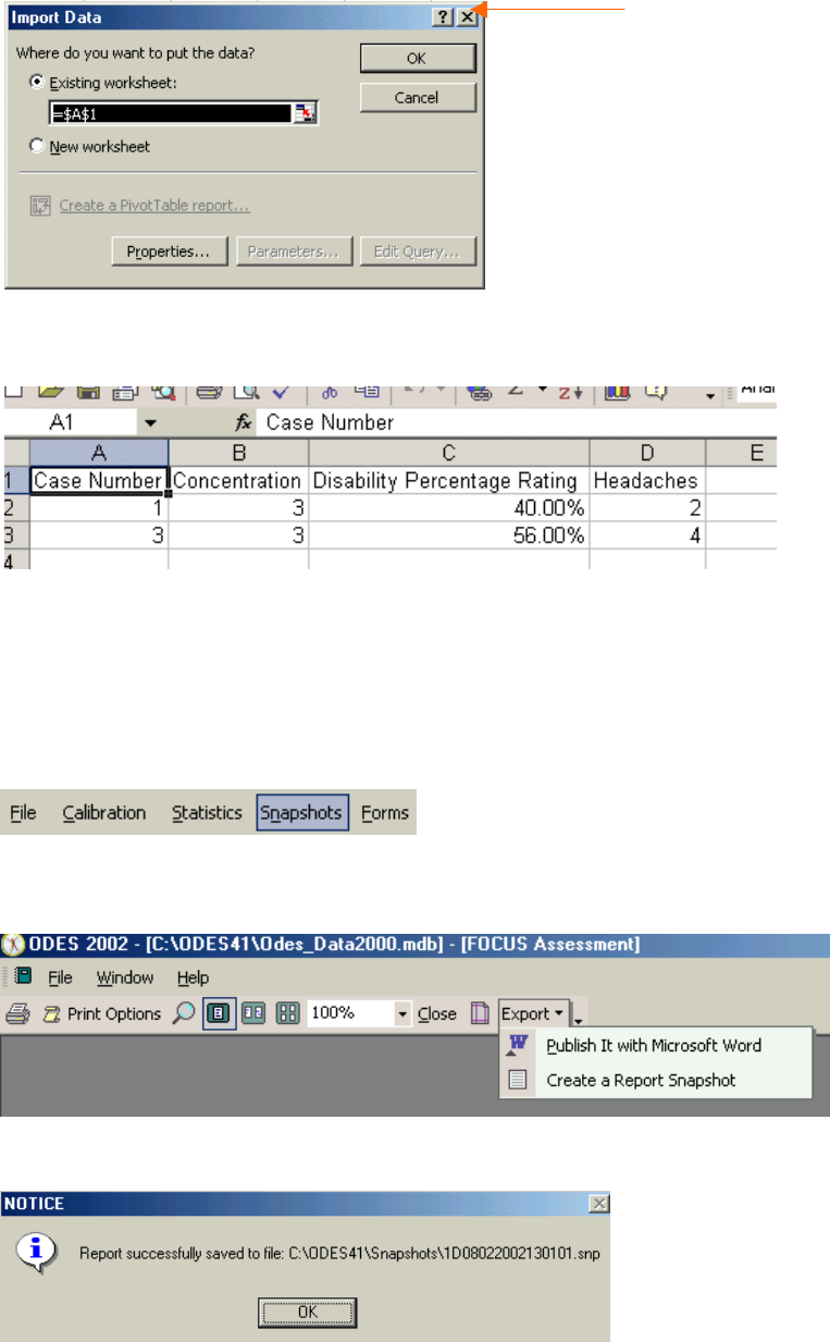
93
You information will now be put into Microsoft Excel Spreadsheet format (see below):
Snapshots
The snapshot function allows users to create “PDF-like” files from reports that can be emailed
without compromising the validity of the document. A snapshot viewer executable file is bundled
with the report file, which will allow individuals without ODES to view the reports (i.e. insurance
companies, other offices, etc.).
In order to use this function, you must first preview the report you want to send as a snapshot.
Once in the print preview for your report, select Export Ň Create a Report Snapshot.
The report will now be exported into a report snapshot, and you will see the following message:
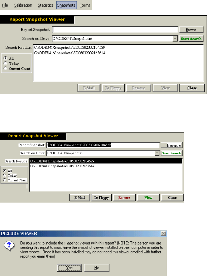
94
In order to access the snapshot file for emailing, printing or saving to a floppy disk, you must first
return to the ODES main page. Select Snapshot and the following page will appear.
You may search for your snapshot by selecting Current Client, Today or All. In order to perform
any function with the snapshot, you must double click the snapshot you wish to use so that it
appears in the Report Snapshot field.
You may now E-Mail the snapshot you selected, save it To Floppy disk, Remove it or View it.
If you choose to E-Mail it, ODES will ask you if you wish to include the snapshot viewer. If you
are emailing the file to someone who has not viewed a snapshot before or does not have ODES,
you must include the snapshot viewer. Make sure that they are aware the viewer will be included
in the email, as some firewalls and virus-checking software will block or screen .exe files.
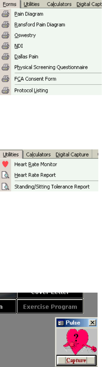
95
Forms Menu
A variety of questionnaires and forms are available for printing from the Forms menu. The client
can fill out these forms and the information can be entered into the software manually later on.
Utilities Menu
Heart Rate Monitor
This feature opens a window, which allows you to monitor a client’s heart rate even outside of a
testing page. Click Capture to initiate the Heart Rate Report. The software will then record the
date, time, and heart rate of the client, as well as what the client was doing when the heart rate
was captured (i.e. Before starting the Standard Hand Grip Test). If Capture is selected on a non-
testing page, the evaluator can enter information regarding the client’s activities at the time.
Standard entries can be set up under Administration Ň Heart Rate Comments. Prior to clicking
OK on the page to close it, make sure there are no errors, as the data cannot be corrected later.
You may also double click the question mark to manually enter the client’s heart rate. Input the
value and hit the Enter key.
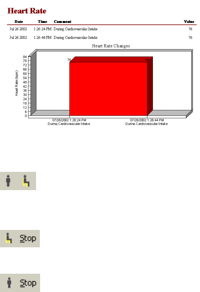
96
Heart Rate Report
This report provides the evaluator with any heart rate information that has been manually entered
into testing pages, or cardiovascular intake pages. It includes date, time, comments and the
heart rate value. This report is not integrated with the report section of the software and must be
printed from here and included as an appendix to the report.
Sitting and Standing Tolerance
t the top of the ODES Menu you will see the following icons:
These icons can be used to track both the sitting and standing tolerances of a client.
In order to time a client sitting, click the sitting icon. Once the client has finished sitting, click the
stop button.
In order to time a client standing, click the standing icon. Once the client has finished standing,
click the stop button.

97
When the assessment is complete, you may print off a sitting/standing tolerance report by going
to UtilitiesŇ Sitting/Standing Tolerance Report. The following is an example of what you will see.
The report includes total sitting or standing time, date, time and duration each position was
maintained.
98
Post Offer of Employment Software (Optional Upgrade)
The Post Offer of Employment software feature allows the evaluator to set the employment
standards for an employer, generate a letter acceptable for the Human Resources department,
and the ability to generate statistics on the hiring of a particular employer.
To access the Post Offer of Employment Test software feature click on POET from the drop down
menu.
POET Receipts
This software feature allows the creation of a receipt in the event the client is required to pay for
the POET test. Select the payment type, and the amount. From the drop down menu the
supervising practitioners listed in ODES will be available. To enter in another name that the
money was received by type it in.
If you are going to create any customized test particular for the employer you are
going to be working with, it is recommended you create the tests before setting the
standards.

99
Set Standards
Select Set Standards from the drop down menu. Select the employer from the drop down menu.
The employer must have been entered in a client’s case at least once for it to be available from
the drop down menu.
Next select the tests you are going to include in the Post Offer of Employment Test for this
particular employer from the drop down menu.

100
From here you would include the External ID, if the results were being exported to a FAT file for
synchronization with the employer’s computer system. Include the standards for the particular test
in the white box (in this example it is “0”).
Next you are required to select the comparison method for the standard you entered. The
following are the options available:
Compare the score for each column with the standard for that column
Compare the left hand score with the standard for the left hand, and compare the right hand
score with the standard for the right hand
Compared the combined maximum of the right and left hand scores with the left hand standard
Compare the hand that scored the higher of the two hands with the higher of the two standards.
Compare the hand that scored the lower of the two hands with the lower of the two standards
Compare the dominant hand score with the higher of the two standards. Compare the non-
dominant hand score with the lower of the two standards
Then select from the drop down menu whether “The evaluee must fail all or only one of the
standards defined above to fail this individual test.”
Once set up, select the next test from the drop down menu to be included in the Post Offer of
Employment Test and set up the standard. Continue until all the standards have been set up for
this particular employer.
POET Standards Report
Once completed click on Print from the Set Standards screen or select POET Standards Report
from the POET drop down menu from the main screen of ODES.
101
Click on Next to be taken to the next screen.
Select the particular employer from the drop down menu and click Next.

102
If a Super Protocol was set up for the Post Offer of Employment Test, select it from the drop
down menu at the top of the screen and then click on Select Tests. You can review the tests that
are included then in the list below and the tests assigned to the particular Super Protocol you
selected should be highlighted. Alternatively, you can select the particular tests from the list of
tests. Once this step has been completed click on Next.
Select whether you want to Preview the report or Print the report. Then click on Finish. The
following is an example of the report. Click on the printer icon to send the print job to the default
printer. Click on Print Options to select which printer to send the report to. Click on Close to close
out of this screen and return to the main screen of ODES or click on Export to export the report to
Microsoft Office Word (if installed on computer) or to export the report to a Snapshot (see section
of creating snapshots for further details).

103
POET Summary Report
The POET summary report will allow you to generate statistics on the number of POET tests
completed for a particular employer for a particular date range. It will provide details on the
number of tests completed and the number and percentage of males and females that passed
and failed the tests. To generate a POET Summary Report select this option from the POET drop
down menu. Click on Next to take you to the next screen.
Select the appropriate employer from the drop down menu and the click on Next.

104
Select the statuses you would like to collect data on. The status is assigned to the client’s case.
Examples of statuses that are used for Post Offer of Employment Tests are: Candidate, Present
Employee, Recall, Did Not Test, No Show. Select “Include employees with no status”, if you
would like to include the data where the evaluator forgot to assign a status. Click on Next to
continue to the next screen.
If a Super Protocol was set up for the Post Offer of Employment Test, select it from the drop
down menu at the top of the screen and then click on Select Tests. You can review the tests that
are included then in the list below and the tests assigned to the particular Super Protocol you
selected should be highlighted. Alternatively, you can select the particular tests from the list of
tests. Once this step has been completed click on Next.

105
Next select the data range you wish to select the data from.
Select whether you want to Preview the report or Print the report. Then click on Finish.
106
The following is an example of the report. Click on the printer icon to send the print job to the
default printer. Click on Print Options to select which printer to send the report to. Click on Close
to close out of this screen and return to the main screen of ODES or click on Export to export the
report to Microsoft Office Word (if installed on computer) or to export the report to a Snapshot
(see section of creating snapshots for further details).
POET Detailed Summary Report
The POET Detailed Report is used to generate a letter to provide to the employer to indicate
whether the client met the job demands or not.
Click on Next to take you to the next screen.
Prior to completing this report make sure your clinic information and logo are included
under Administration ŇClinic Information.
107
Select whether you want to report to include the current client or all the client’s for a particular
employer.
Select the appropriate employer and click on Next.
108
Select the status of the client(s) and then click on Next.
109
If a Super Protocol was set up for the Post Offer of Employment Test, select it from the drop
down menu at the top of the screen and then click on Select Tests. You can review the tests that
are included then in the list below and the tests assigned to the particular Super Protocol you
selected should be highlighted. Alternatively, you can select the particular tests from the list of
tests. Once this step has been completed click on Next.
Next select the data range you wish to select the data from and click Next to continue to the next
screen.

110
Select whether you want to Preview the report or Print the report. Then click on Finish.
The following is an example of the report. Click on the printer icon to send the print job to the
default printer. Click on Print Options to select which printer to send the report to. Click on Close
to close out of this screen and return to the main screen of ODES or click on Export to export the
report to Microsoft Office Word (if installed on computer) or to export the report to a Snapshot
(see section of creating snapshots for further details).

111
Export POET Results
This feature is used to export data to a FAT file to synchronize the data to the employer’s
computer Select the Super Protocol for the employer to be exported and the date range of tests
completed. Either type in the Export File Path or click on Browse to select where to export the file
to. Type in what you would like to call the Export File. Select to append the current date to the file
name if you would like today’s data added to the file name to distinguish when the export was
completed and prevent a mix up of files.
112
Digital Capture Menu
For those evaluators with access to a digital camera, a variety of pictures can be saved to your
computer and input to the ODES software. You may use this feature to show a client performing
tasks or exercises. Comments and headings can be added to each picture prior to printing them.
Take the picture with the digital camera. Download the picture to your hard drive using your
camera software. Use the binoculars button to locate the picture, then click Insert. Once inserted,
the file name will be included below the photo. Include a page title and the top of each new page.
Include any comments by clicking Comments.
Click Remove to remove a picture.
To insert a new page, click New. Each page will hold nine pictures. To delete a page click Delete.
To print an entire page of pictures and comments, click Print.
113
Help Menu
Help Manuals
If you have loaded the Adobe Acrobat reader and help manuals onto your hard drive from the
ODES installation disk, you will be able to access them by going to Help ~ Help Manuals. If you
have not loaded the Acrobat reader and Manuals to your hard drive, a window will prompt you to
insert the ODES CD into your disk drive. To load the Adobe reader go to www.adobe.com to
down the reader.
About
To access information on your system go to Help ~ About. On this page, details on the ODES
software version you are using can be obtained. If the system has not been unlocked, ‘Days
Remaining’ indicates for how long you will be able to use the system. The ODES software can be
unlocked by calling BTE Customer Service. Once unlocked, Days Remaining will display as
‘Unlimited’. ‘Machine #’ is set to ‘None’ unless the system has been purchased on a utilization
basis. The ‘Serial #’ for the system is also included here. The System Info button located at the
bottom of this window will also provide you with statistics on your system, such as amount of
memory and operating system.
To manually update the database after installing software updates go to Help ~ About. Hold the
Shift key down, and hit the ‘Z’ key three times.
114
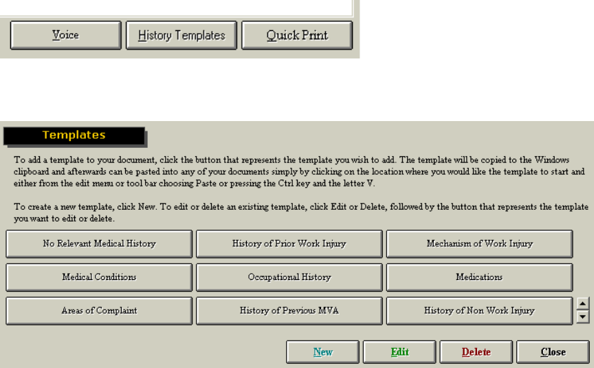
115
Templates
Each of the note pages in ODES has a template section that allows the evaluator to create any
number of templates. Using this feature the evaluator can have any field from the client and case
information automatically populate a template when applied to the client’s file. For example, the
client’s name, date of injury and injury locations could be brought into the note exactly where you
designed the template to put them. This feature speeds up reporting time, improves efficiency
and hence, profitability. There are a variety of headings under which templates can be created.
These include:
History
Examination
Diagnosis
X-Rays/Lab
Referral
Impairment
Return To Work
Custom Note
Testing Analysis
Recommendations
Progress Analysis
Cover Letter
There are also a variety of pre-programmed templates in the ODES software. To access or
create a new template in any of the above categories, you must first choose a note from the list
above and then click the template button located in the bottom right-hand corner of any page.
This will bring you to a page where the pre-programmed templates are located. You may delete,
add or edit templates here.
To utilize an existing template, click the template you wish to use. You will be brought back to a
blank page. Place your cursor where you would like to paste the information and click the paste
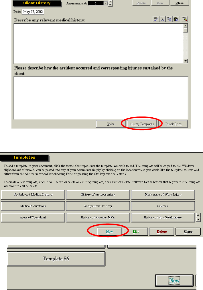
116
icon. Your template will now fill in the appropriate information for your client. In order to alter any
remaining fields that have not been filled, use your tab button and make the necessary changes.
Creating a Custom Template
–To create a custom template click the template button on the note page to which you wish to
add the template (i.e. History, Examination, etc.)
Click NEW to create a new template.
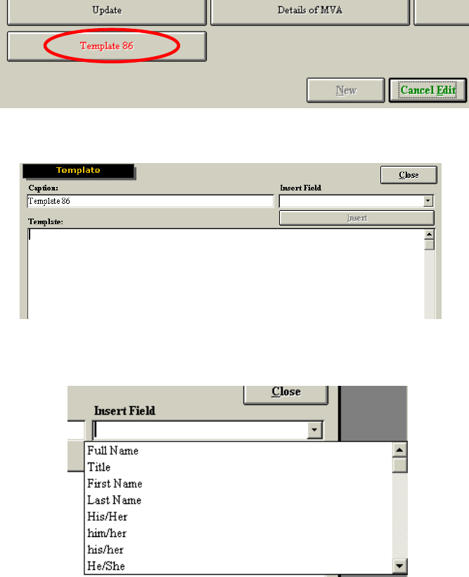
117
Click Edit then select the new template (in this case Template 86) in order to add text and change
the template name.
ODES has multiple pre-programmed fields in order to help you build your template. These fields
include names, times, dates, results, status, etc.
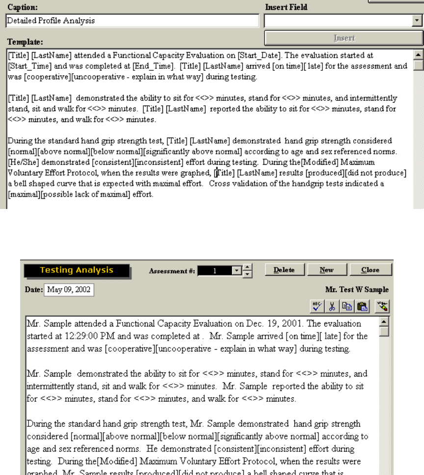
118
Begin by writing what you wish to include in the report, but use the merge fields in order to
automatically query data. To use the merge fields, select the field from the Insert Field dropdown
menu and click Insert. This will place the merge field in the template at the spot where your
cursor was located. The merge field will have square brackets around it.
You may create your own merge field by typing the possible options and placing square brackets
around each one. This is useful in situations where there are a limited number of options (i.e.
“arrived [on time][late] for the assessment…”).
Once finished, click Close, then click Cancel Edit on the Template page. Select your template
and paste it into place
You may now use the “tab” key on your keyboard to find and replace any outstanding fields on
the template. Remember that you will need to choose the appropriate comments in certain
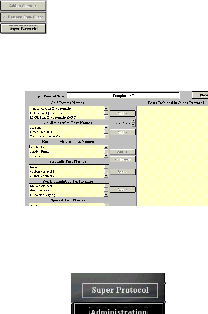
119
circumstances (i.e. normal, above normal or below normal). Click on delete to remove a selection
or click on tab again to allow the selection to stay.
Super Protocols
Super Protocols can be created when you require a standardized protocol for testing (i.e. Post
Offer of Employment Testing). They can also be used if you want to decrease the amount of time
required to select specific tests for a specific injuries. You can create a Super Protocol in the
same manner you would create a template.
Select a client and click Super Protocol from any testing page. Click New Test and then Edit the
protocol to include the tests applicable to your needs.
Select the applicable tests from the lists on the left-hand side of the page and Add them to the
Super Protocol. The order of testing can be changed by selecting one of the included tests and
using the Change Order arrows to move it up or down within the list. Once you have added all the
applicable tests and arranged them in the desired order finish the process by clicking Lock Super
Protocol. You will be prompted to enter and confirm a password to lock the Super Protocol.
To apply a Super Protocol, select a client then click Super Protocol from either the ODES main
menu or from a page where tests are selected. Click the Super Protocol you wish to use. The
tests for that protocol will automatically be added to your client once you have performed the first
test. Click Next Protocol to go to the next test in sequence.
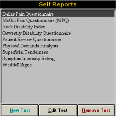
120
Self Reports Menu
Self Reports can be printed from the Forms menu or from the test page if the evaluator would like
the client to them out on paper, with the exception of the Spinal Function and Hand Function
reports. The client may also complete the reports on the computer. To view the results after the
client has completed a report, click Show. To hide the results, if the client can see the computer
screen, click Hide.
Dallas Pain Questionnaire
The DPQ was developed to assess the amount of chronic pain affecting four aspects of the
client’s life: daily activities, work-leisure activities, anxiety-depression and social interest.
The DPQ has 16 sections, divided between the four aspects. The questionnaire utilizes a Visual
Analogue Scale (a pain-free state being to the left and the most painful state being to the right).
The Visual Analogue Scales are 10 cm long. The questionnaire must be answered by placing an
“X” on the Visual Analogue Scale at the appropriate pain rating
McGill Pain Questionnaire
The McGill Pain Questionnaire (MPQ) is a tool that has been widely recognized as a reliable
instrument to measure the pain experience, and has been translated into many languages and
widely researched. Pain descriptors cover four aspects: sensory, affective, evaluative and
miscellaneous. The MPQ has been demonstrated to be a good instrument for clinical work and
research. At the bottom of the report you have the option of including the score on the report or
not.
The Neck Disability Index (NDI)
The Oswestry Low Pain Index was modified to produce a 10-item scaled questionnaire entitled
the Neck Disability Index (NDI). The NDI is designed to inform the doctor as to how the client’s
neck pain has affected their ability to manage in everyday life. It has been offered as a self-
reporting instrument for the ADL (Activities of Daily Living) assessment of sufferers of disabling
neck pain, particularly from whiplash injuries. The NDI demonstrates a high degree of test-retest
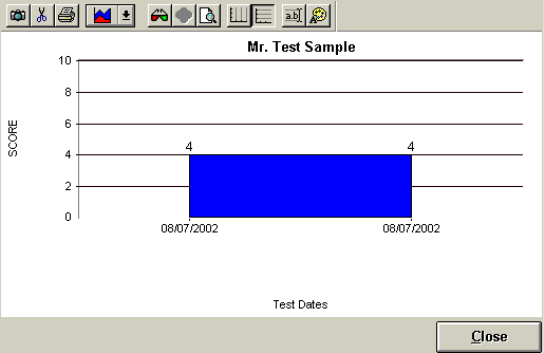
121
reliability and internal consistency. The evaluator has the option of printing a progress graph for
the NDI once a minimum of two tests have been completed. The graph can be printed by clicking
New Test from the testing page, then clicking Progress. Alternatively, the NDI progress graph will
be included with a Progress Report if that report is printed (see the Reports section).
The Oswestry Questionnaire
The Oswestry LBP Questionnaire is divided into ten sections designed to assess limitations in
various activities of daily living. Each section contains six statements relevant to the problems
suffered by people with low back pain. This self-administered questionnaire avoids interviewer
bias and ensures uniformity of presentation while the combination of closed questions and self-
administration gives a reliable format. The evaluator has the option of printing a progress graph
for the Oswestry LBP once a minimum of two tests have been completed. The graph can be
printed by clicking New Test from the testing page, then clicking Progress. Alternatively, the
Oswestry LBP progress graph will be included with a Progress Report if that report is printed (see
the Reports section).
Patient Review Questionnaire
The Patient Review Questionnaire takes a look at a client’s progress over the course of a
rehabilitation program. In addition, this questionnaire also takes into account changes in
medication relating to neck pain over the course of the program. This questionnaire was designed
for the Melbourne Protocol with the BTE Multi-Cervical Unit.
Once the patient has completed multiple Client Review Questionnaires, a progress report can be
created illustrating whether improvement has occurred over time. This report is in the form of a
graph.
Superficial Tenderness
The superficial tenderness test allows for an objective analysis of chronic pain with disorders
such as fibromyalgia. Please refer to the Algometer section of this manual for more details.
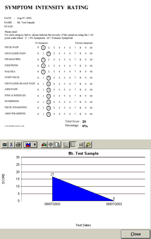
122
Symptom Intensity Rating
The Symptom Intensity Rating Questionnaire is a tool in which the client rates their symptoms
throughout a treatment program. Upon completion of more than one questionnaire, a graphical
progress report can be printed. This questionnaire was designed for the Melbourne Protocol
using the BTE Multi-Cervical Unit.
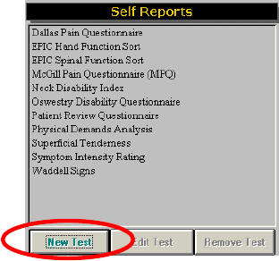
123
Waddell Signs
The Waddell Signs test is a standardized assessment of behavioral responses to examination.
When completing the Waddell tests, select ‘positive’ or ‘negative’ as per the test protocol. The
score for the test can be found at the bottom of the page.
Physical Demands Analysis
This portion of the software is designed to gain additional information from your client regarding
their pre-injury employment. It requires your client to describe their duties at work (as they
perceive them to be).
Go to the Self Report section of the software, select Physical Demand Analysis and click Perform.
You may print a blank form for the client to fill out.
Creating Custom Self Perception Tests
The ODES software allows you to customize your own self-perception tests (such as
questionnaires). In order to do so, you must go to the Self Reports page and click NEW TEST.
This will bring you to a template page where you can begin to create your new self-perception
test.

124
You will be able to include section titles, which will let you add a score to them in the test screen.
Add in the name for the Final Score Column. If you are entering ratings based on a research
article, select the Rating Column and add in the name for the Rating Column. To add a rating
complete the rating entries box and include the rating to and from. Click on Add to include the
rating. You may also include any examiner or report descriptions here. Examiner descriptions are
only seen in the testing screen. Report descriptions are only seen on the printed report.

125
EPIC Hand Function Sort (Optional Upgrade)
The purpose of the 62-item Hand Function Sort (HFS) is to quantify the disabled person's
perception of their ability to perform work tasks that involve the hands and upper extremities.
The HFS can be useful to provide a baseline measure of the client's perception of their
functionality in everyday tasks prior to the onset of intervention. This allows progress to be noted
as it occurs, extending the benefits of treatment beyond the clinic's walls into the client's life at
home, at work, and in the community.
In the HFS, drawings of handling and fingering tasks are supplemented by drawings that depict
common activities of daily living. The drawings have been selected by experts in rehabilitation
from among hundreds of tasks that persons with upper extremity impairments report as
presenting significant challenges.
The client is instructed to "Look at each drawing and read the description. On a separate answer
sheet, indicate your current level of ability to perform the task."
The answer sheet provides a 5-point rating from "Able" to "Restricted" to "Unable." Operational
definitions of these adjectives are provided in the standardized instructions. There is also a sixth
rating, depicted as "?", which indicates "I don't know."
The HFS is not timed and usually requires 8 to 10 minutes to complete. It can be administered by
a technician by following the standardized instructions
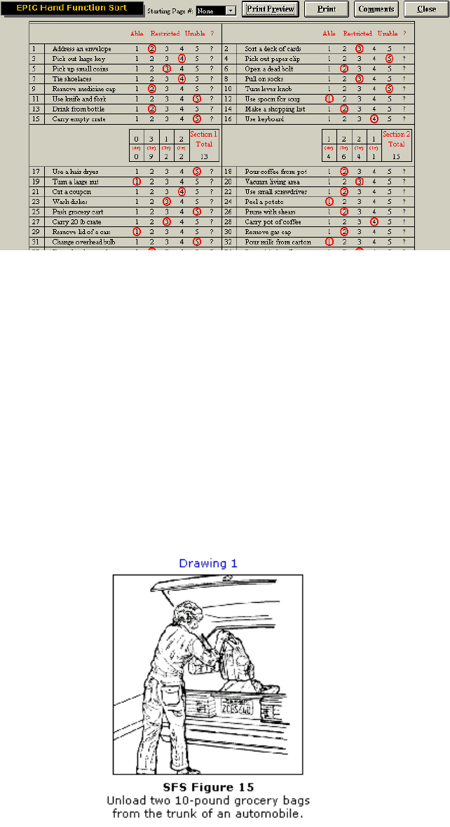
126
Once the test is performed with a client, the results will be shown in a chart.
The HFS is easily scored and yields a single "Rating of Perceived Capacity" which ranges from
zero to 248. Three "internal validity check" drawings are included which are similar to drawings
presented earlier.
Normative values for both healthy and disabled males and females are provided in the HFS
examiner's manual. Additionally, the Rating of Perceived Capacity score can be cross-referenced
to the U.S. Department of Labor's Physical Demand Characteristic of Work system.
The normative values allow the evaluator to compare functional test results, the HFS score, and
the target job's demands, providing a crucial three-way cross-validation of findings.
EPIC Spinal Function Sort
The purpose of the 50-item Spinal Function Sort (SFS) is to quantify the disabled person's
perception of their ability to perform work tasks that involve the spine. This can be useful to
provide a baseline measure of the client's perception of their functionality prior to the onset of
intervention.
The client is instructed to "Look at each drawing and read the description. On a separate answer
sheet, indicate your current level of ability to perform the task."
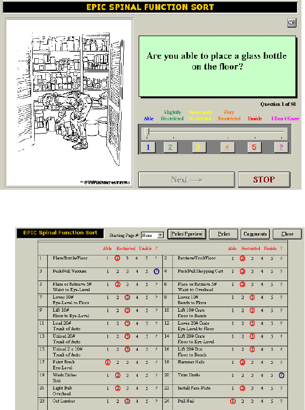
127
The answer sheet provides a 5-point rating from "Able" to "Restricted" to "Unable." Operational
definitions of these adjectives are provided in the standardized instructions. There is also a sixth
rating, depicted as "?", which indicates "I don't know."
The test is not timed and usually requires 8 to 10 minutes to complete. A technician can
administer it by following the standardized instructions.
Once the test is performed with a client, the results will be shown in a chart.
The SFS is easily scored and yields a single "Rating of Perceived Capacity" which ranges from
zero to 200. Two "internal validity check" drawings are included which are similar to drawings
presented earlier.
Normative values for both healthy and disabled males and females are provided in the SFS
examiner's manual.
Additionally, the Rating of Perceived Capacity score can be cross-referenced to the U.S.
Department of Labor's Physical Demand Characteristic of Work system. This allows the evaluator
to compare the FCE results, SFS score, and the target job's demands, providing a crucial three-
way cross-validation of findings.
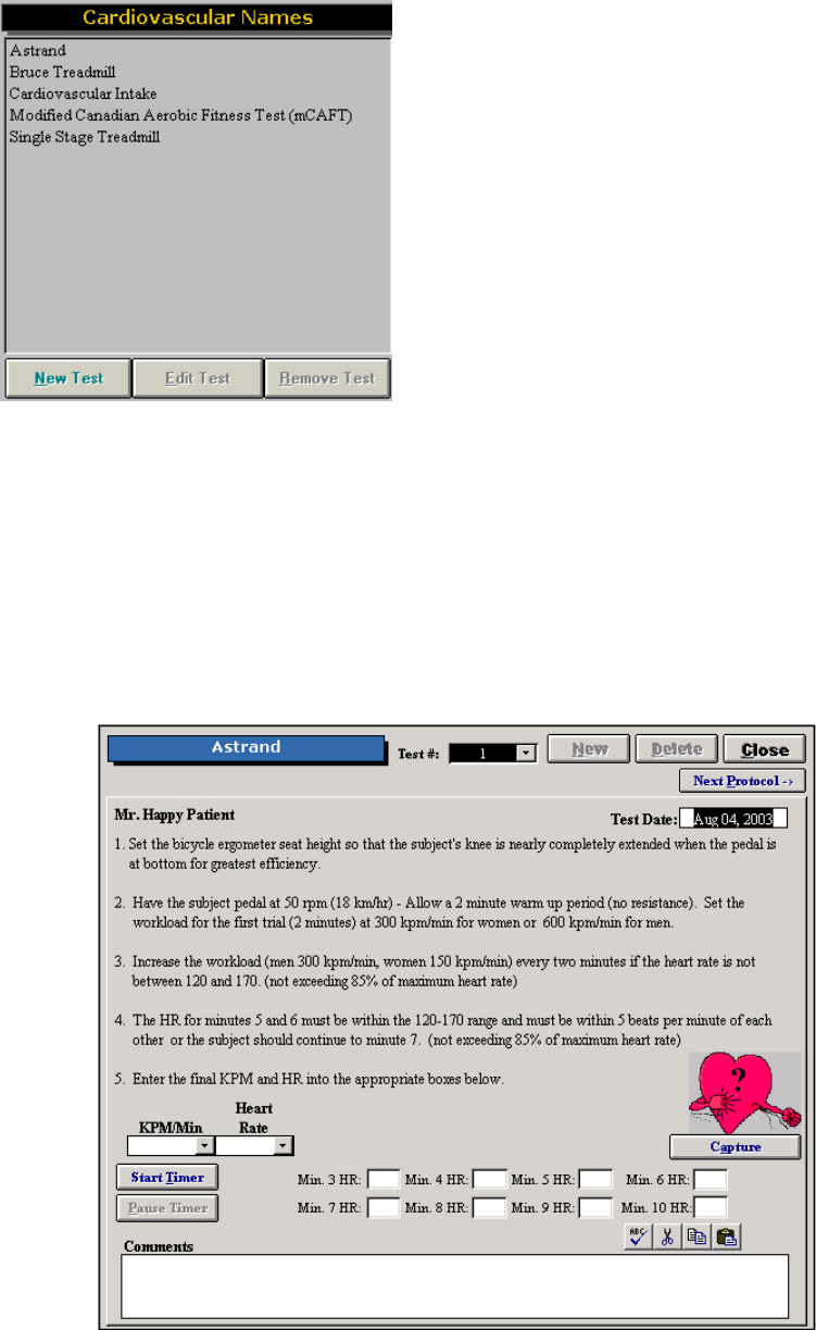
128
In a multi-site study of the California Functional Capacity Protocol (Matheson, et al, 1996), the
authors demonstrated that SFS test results are closely linked to work capacity performance
measures. Furthermore, the SFS provided the best single indicator of client effort.
Cardiovascular Menu
A variety of cardiovascular tests are included in the software for you to utilize.
Astrand
The Astrand protocol is a bike ergometer test used to determine a client’s aerobic capacity. The
software can be used in two ways. The test can be completed away from the system and the
KPM/min and final heart rate entered. The software will calculate the aerobic capacity for the
client. Alternatively the test can be completed on an integrated fashion with ODES. The evaluator
can click on Start Timer and if the client has the heart rate monitor on, the heart rate will be
captured each minute after the first three minutes of the test until the client’s stead state heart
rate is obtained. Click on Capture to add the heart rate value to the Heart Rate Report.

129
Bruce Treadmill
The Bruce Treadmill test is used to determine a client’s aerobic capacity. Both the modified and
standard protocol is available in the ODES software. Click on Standard or Modified on the top
right hand corner of the screen to switch to the other protocol. Click on Start Timer when starting
the test. Click on Pause Timer if the test must be paused to clarify to the client what they are
required to do or for safety reasons. To stop the test click on Stop Timer and the aerobic capacity
will be calculated. Click on Capture to add the heart rate value to the Heart Rate Report.
Cardiovascular Intake
Cardiovascular Intake allows for the recording of the client’s resting heart rate and blood
pressure. If the client is wearing the heart rate monitor, double click on the white box under the
title, resting rate (min) and the value will be entered in the box. The software will alert you if the
value is indicates a high resting heart rate or blood pressure by the text turning red in the result
section of the screen.

130
Modified Canadian Aerobic Fitness Test
The Modified Canadian Aerobic Fitness Test is used to determine a client’ aerobic capacity and
the number of METs they can work at by stair climbing.
Prior to completing the test the resting heart rate and blood pressure need to be entered under
Cardiovascular Intake. As well make sure the client has completed a PAR-Q or health
questionnaire to identify any contraindications to cardiovascular testing. The client should be
wearing the heart rate monitor during testing. If the heart is being captured manually, double click
on the heart. Enter the number in and hit enter for the heart rate to be entered into the software.
To provide a demonstration for the client, double click on either the single or double step stick
figure diagram. Click on Cadence Off if you are using a metronome or tape to prompt the client.
Begin testing at the appropriate level as indicated on the screen (i.e. Cadence 84 steps/minute
and 2 steps with this example). At the end of each 3-minute interval the heart rate is entered.
The computer will alert you as to whether to continue testing or not. Measure blood pressure as
per the protocol at the 2:00 to 2:30 minute mark, the 3:30 to 4:00 minute mark and prior to them
leaving your clinic.
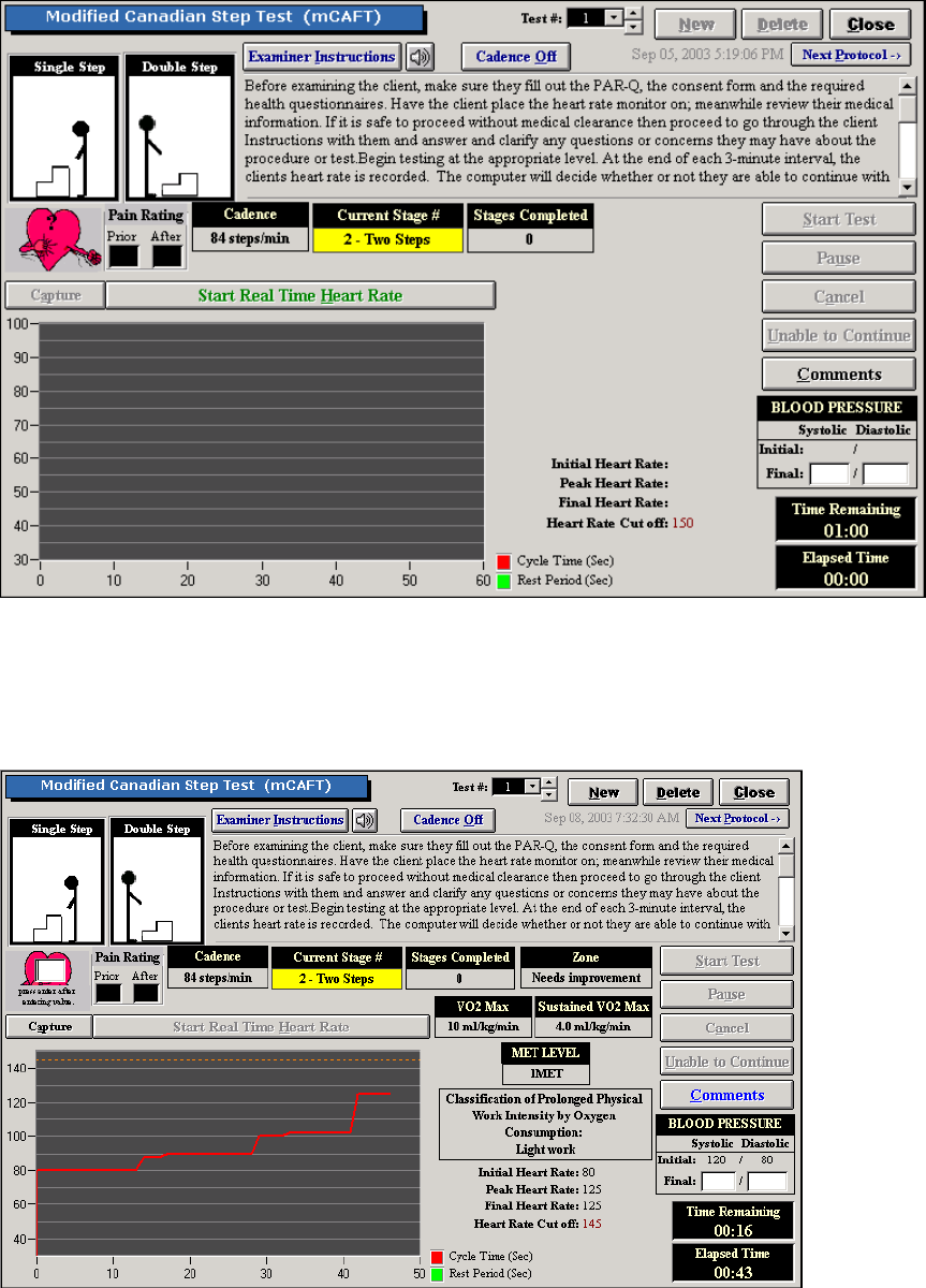
131
The test will stop automatically when they have completed the protocol or click on Unable to
Continue if the client voluntary stops the test. Click on Pause if you need to clarify instructions for
the client.
Once testing is completed the computer will calculate the client’s VO2 and MET level.
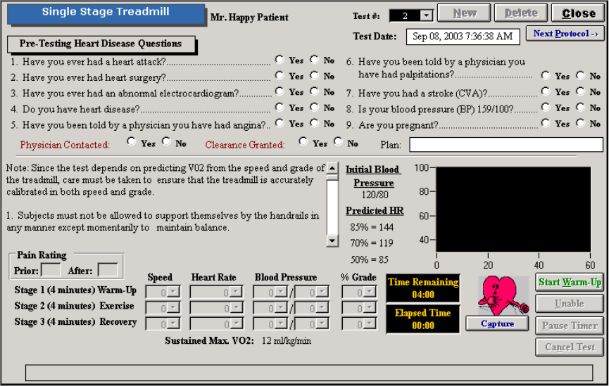
132
Single Stage Treadmill
The Single Stage Treadmill test is used to determine a client’s aerobic capacity and MET level.
The test is based on the treadmill’s speed and grade and so it is important the treadmill is
calibrated regularly. Refer to your treadmill user manual for more details on this or contact the
manufacturer.
Prior to completing the test complete the Pre-Testing Heart Disease Questions. Contact the
client’s physician for medical clearance if any of the answers are yes.
During testing the client is not allowed to hold onto the handrails of the treadmill for balance. Each
stage is 4 minutes long with the heart rate and blood pressure being measured during the final
minute of each stage. Begin the first one to two minutes of the test by selecting a comfortable
pace for the client. Increase the speed to between 2.0 and 4.5 mph depending on the condition of
the client. Increase the incline the grade by 5% maintaining a final speed of warm up stage. Stage
two begins when the grade reaches 5%. Decrease the grade and speed for stage three.
The following is the screen when the test is completed.
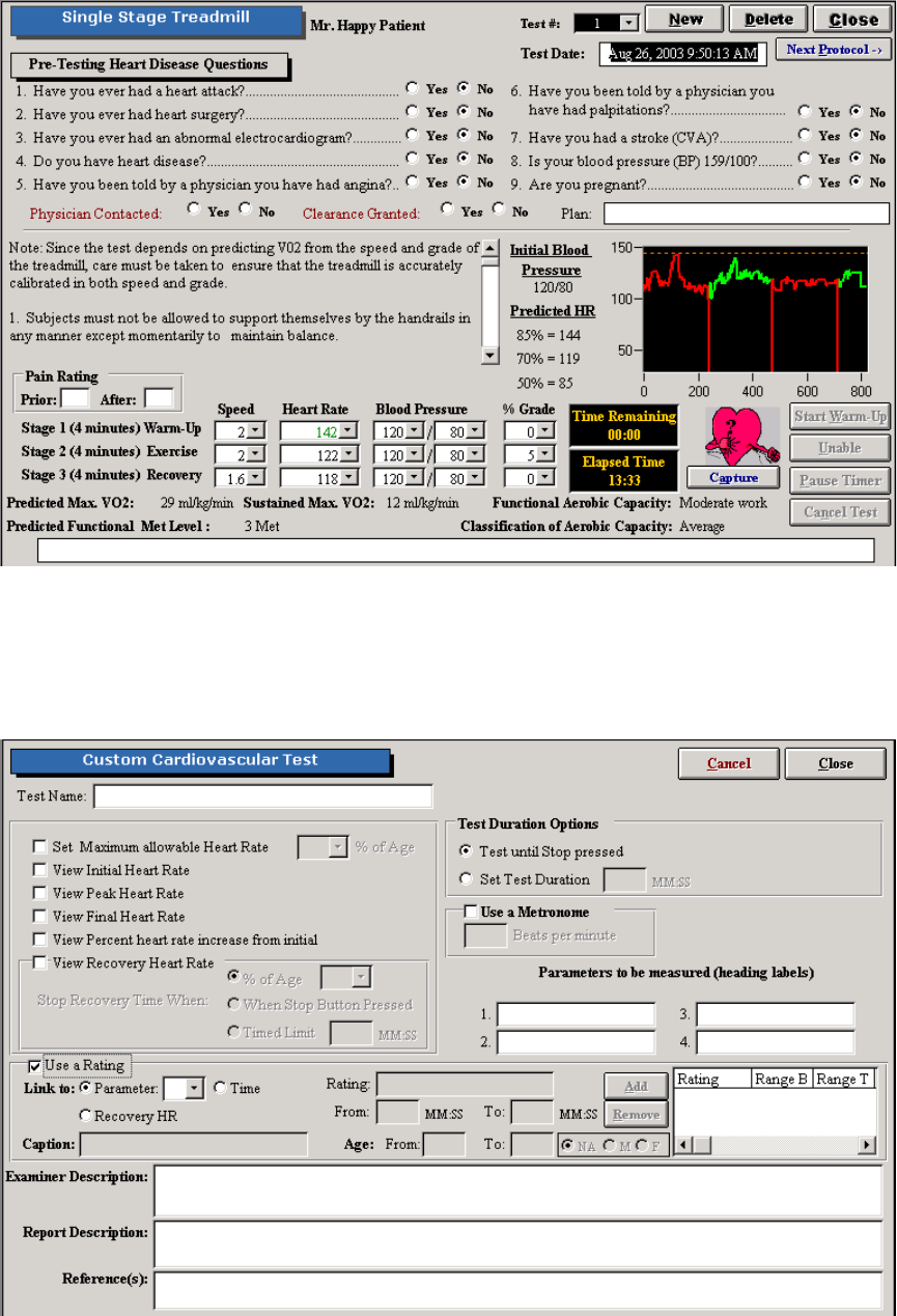
133
Customized Cardiovascular Tests
From the Cardiovascular menu you may also create your own cardiovascular test by clicking New
Test.
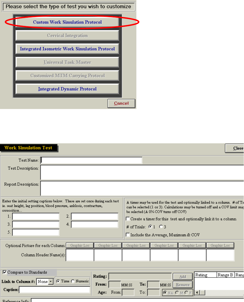
134
Include the parameters for the test based on the protocol you have selected. Click on Close to
save the protocol.
Creating a Non-Integrated Work Simulation Protocol
Within ODES you have the ability to create either a non-integrated work simulation test.
After clicking New Test, located on the Work Simulation Protocol screen, the following menu will
be displayed:
From this menu, select Custom Work Simulation Protocol. This type of test allows you to create
any non-integrated work simulation protocol, such as: carrying, lifting, balancing, climbing,
walking, dynamic pushing/pulling, etc.
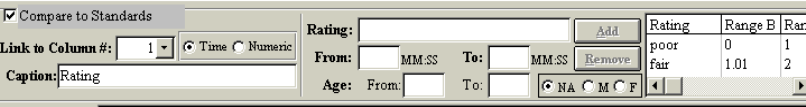
135
Include the test name, test description, report description, initial settings (if any), number of trials,
and column header name fields. If the test is timed, select “Create a timer for this test and
optionally link it to a column.” Once the timer has been selected below the Column Header
Names you will have access to buttons below the graphic locations called Timer Linkage. Click on
the one where you would like the time linked to. Once the button has been clicked it will say
Timer On.
You are also able to incorporate standards based on research into your test by entering ratings.
First select which column you will be using the value obtained to compare against the standards.
Select this from the drop down menu titled “Link to Column”. Select whether the value is numeric
or a time. Include a caption so that you will be able to enter in the ratings (i.e. Percentile, Rating
etc). Now you can enter in all the normative data and related it to age and sex if indicated in the
research. Click on Close to save the test.
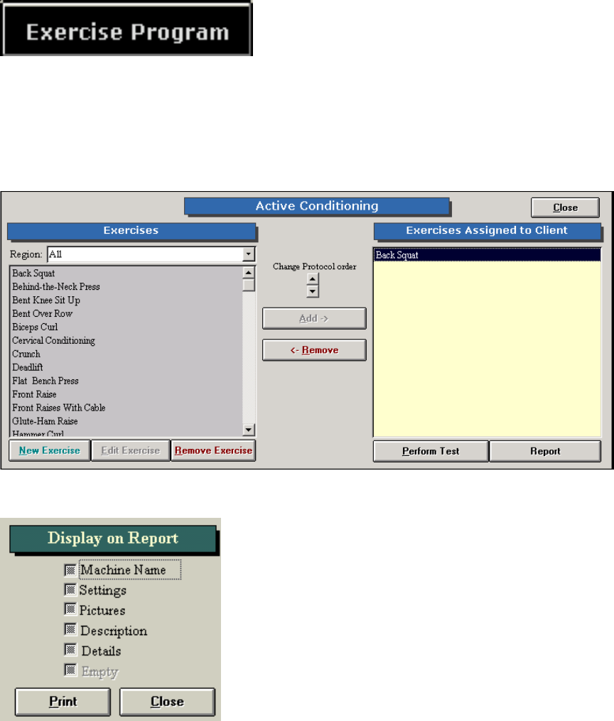
136
Exercise Program/Cervical Conditioning
a) Exercise Program
ODES comes with a variety of pre-programmed exercises you can. include within your client’s
program. You may click Perform Test to conduct the exercise, or print out a Report to allow the
client to track their progress manually.
You can customize your report to include any of the following pieces of information:
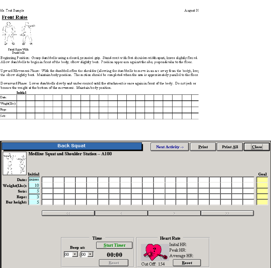
137
Click on Perform Test to enter information for the client’s exercise.
The initial weight, sets, repetitions and other parameters can be entered in and the goals for the
exercise.
To add in a new exercise or work simulation protocol click on New.
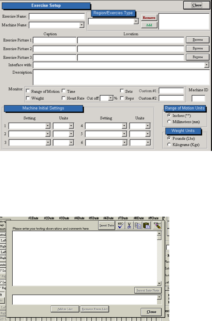
138
Fill out the required parameters and click on Close to save the information.
Comments
All testing screens allow for evaluator comments to be added in. A box will be available on the
screen or a Comments button can be clicked on.
To enter notes, place your cursor in the larger blank text box. Type any information that you wish
to include. If you wish to include to date prior to entering your note, click Insert Date n (located on
the tool bar). The date will now appear in the text box.
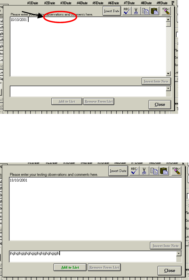
139
You may also enter information into a template. This allows you to save popular phrases so that
you do not have to re-enter them time and time again.
To create a template, enter the information you wish to save in the smaller text box and then click
Add to List:
The new template will now appear in a dropdown menu.
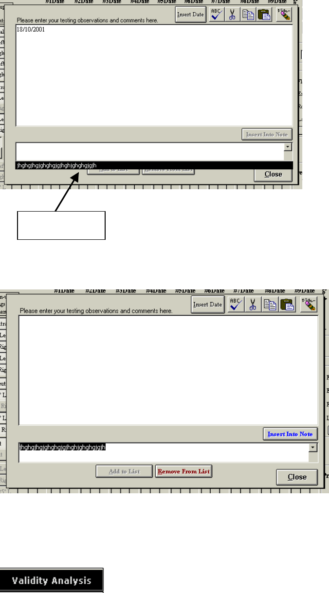
140
To insert this information into your note, select the template you wish to include from the menu
and click Insert Into Note.
The information will now appear in the notes section (the upper text box):
Validity Analysis
Your information
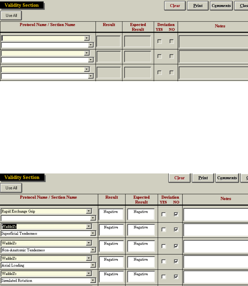
141
This section of the ODES software analyzes the validity of the testing performed on each client.
Validity analysis compares results to expected results for all tests completed by a client, or for
selected tests. This information provides details on what the expected result of the tests should
have been, according to research and the actual result. Click Use All to collect information from
all client tests; to select individual tests, use the dropdown menus. Click Add Validity Item to add
a new test to the current analysis.
Once the information has been reviewed, the total number of deviations will be displayed at the
bottom of the page, and you may add comments regarding the consistency of the performance.
Since this feature is not integrated with ODES reporting, click Print to print out the validity
analysis.
Reports
ODES has the ability to create a variety of different reports.
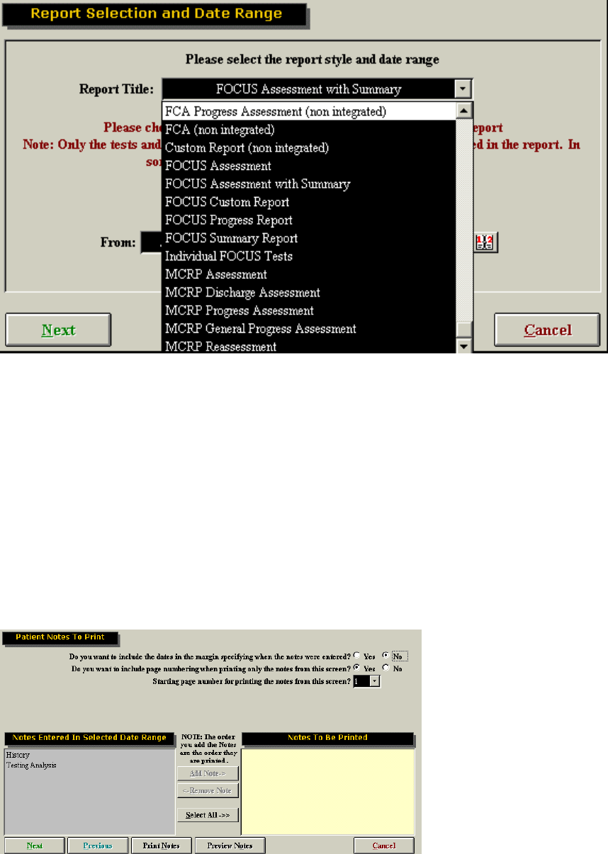
142
Each report has different features. For example, a summary report only contains the actual raw
data that is collected from testing (no verbal comments or information). On the other hand, a
FOCUS Assessment will include all notes, comments and testing data that the evaluator wishes
to include. Custom reports will let you change the name of the report.
All information will be automatically pulled from the tests, making report writing efficient and time
saving. To create a new report simply choose the type of report you wish to use, ensure that the
start and end dates for the notes and protocols are correct and click Next.
You now have the option of including notes. You can add individual notes, or include all notes at
once by clicking Select All. The notes will be printed in the order in which they are listed, with the
exception of Diagnosis and Recommendation notes, which are always printed first. This page
also lets you modify page numbering, and whether dates are included in the margins. If the
supervising practitioner has a digital signature in the system, you will be able to include a
signature line and/or digital signature to the report.
The next page allows you to choose which tests you wish to include in the report.
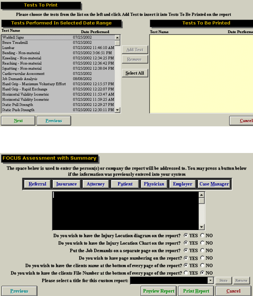
143
Finally, you can include contact information, change page specifications, include job demands
and injury locations, etc. You may then preview your report, or send it directly to the printer.
Types of Reports:
Cervical Assessment:
Allows you to select date range of data
Allows you to add and remove client notes from the report
Allows you to alter page numbers
Allows you to enter dates in the margins beside client notes
Allows you to select all or only specific tests to include on the report
Allows you to print or preview the report
144
MCRP Assessment:
Allows you to select date range of data
Allow you to add and remove client notes from the report
Allows you to alter page numbers
Allows you to address the report to the following: Referral, Insurance Company, Attorney, Client,
Physician, Employer, Case Manager
Allows you to include injury diagram and/or chart on the report
Allows you to put the job demand on a separate page
Allows you to add or remove page numbers from the report
Allows you to include clients name at the bottom of each page of the report
Allows you to print or preview the report
MCRP Discharge Assessment:
Allows you to select date range of data
Allow you to add and remove client notes from the report
Allows you to alter page numbers
Allows you to address the report to the following: Referral, Insurance Company, Attorney, Client,
Physician, Employer, Case Manager
Allows you to include injury diagram and/or chart on the report
Allows you to put the job demand on a separate page
Allows you to add or remove page numbers from the report
Allows you to include clients name at the bottom of each page of the report
Allows you to print or preview the report
MCRP Progress Assessment:
Allows you to select date range of data
Allows you to put the job demand on a separate page
Allows you to add or remove page numbers from the report
Allows you to include clients name at the bottom of each page of the report
Allows you to print or preview the report
MCRP General Progress Assessment
Allows you to select date range of data
Allows you to alter pages numbers
Allows you to add and remove client notes from the report
Allows you to add specific tests to your report
Allows you to address the report to the following: Referral, Insurance Company, Attorney, Client,
Physician, Employer, Case Manager
Allows you to include injury diagram and/or chart on the report
Allows you to put the job demand on a separate page
Allows you to add or remove page numbers from the report
Allows you to include clients name at the bottom of each page of the report
Allows you to print or preview the report
Allows you to create a custom title for the report
MCRP Reassessment
Allows you to select date range of data
Allows you to alter pages numbers
Allows you to add and remove client notes from the report
Allows you to add specific tests to your report

145
Allows you to address the report to the following: Referral, Insurance Company, Attorney, Client,
Physician, Employer, Case Manager
Allows you to include injury diagram and/or chart on the report
Allows you to put the job demand on a separate page
Allows you to add or remove page numbers from the report
Allows you to include clients name at the bottom of each page of the report
Allows you to print or preview the report
FCA Progress Assessment (non integrated)
This report is designed to include only Non-Integrated tests that have been performed. It is
specifically used to track the progress of multiple assessments
Allows you to select date range of data
Allows you to alter pages numbers
Allows you to add and remove client notes from the report
Allows you to add specific non-integrated tests to your report
Allows you to address the report to the following: Referral, Insurance Company, Attorney, Client,
Physician, Employer, Case Manager
Allows you to include injury diagram and/or chart on the report
Allows you to put the job demand on a separate page
Allows you to add or remove page numbers from the report
Allows you to include clients name at the bottom of each page of the report
Allows you to print or preview the report
FCA (non integrated)
Allows you to select date range of data
Allows you to alter pages numbers
Allows you to add and remove client notes from the report
Allows you to add specific non-integrated tests to your report
Custom Report (non integrated)
This report is designed to include only Non-Integrated tests that have been performed.
Allows you to select date range of data
Allows you to alter pages numbers
Allows you to add and remove client notes from the report
Allows you to add specific non-integrated tests to your report
Allows you to address the report to the following: Referral, Insurance Company, Attorney, Client,
Physician, Employer, Case Manager
Allows you to include injury diagram and/or chart on the report
Allows you to put the job demand on a separate page
Allows you to add or remove page numbers from the report
Allows you to include clients name at the bottom of each page of the report
Allows you to print or preview the report
Allows you to create a custom title for the report
FOCUS Assessment
Allows you to select date range of data
Allows you to alter pages numbers
Allows you to add and remove client notes from the report
Allows you to add specific tests to your report
146
Allows you to address the report to the following: Referral, Insurance Company, Attorney, Client,
Physician, Employer, Case Manager
Allows you to include injury diagram and/or chart on the report
Allows you to put the job demand on a separate page
Allows you to add or remove page numbers from the report
Allows you to include clients name at the bottom of each page of the report
Allows you to print or preview the report
Focus Assessment With Summary
The main difference with this report is that a summary chart of all raw data precedes all of the
testing information.
Allows you to select date range of data
Allows you to alter pages numbers
Allows you to add and remove client notes from the report
Allows you to add specific non-integrated tests to your report
Allows you to address the report to the following: Referral, Insurance Company, Attorney, Client,
Physician, Employer, Case Manager
Allows you to include injury diagram and/or chart on the report
Allows you to put the job demand on a separate page
Allows you to add or remove page numbers from the report
Allows you to include clients name at the bottom of each page of the report
Allows you to print or preview the report
Allows you to create a custom title for the report
FOCUS Custom Report
Allows you to select date range of data
Allows you to alter pages numbers
Allows you to add and remove client notes from the report
Allows you to add specific non-integrated tests to your report
Allows you to address the report to the following: Referral, Insurance Company, Attorney, Client,
Physician, Employer, Case Manager
Allows you to include injury diagram and/or chart on the report
Allows you to put the job demand on a separate page
Allows you to add or remove page numbers from the report
Allows you to include clients name at the bottom of each page of the report
Allows you to print or preview the report
Allows you to create a custom title for the report
FOCUS Progress Report
This report is specifically used to track the progress of multiple assessments
Allows you to select date range of data
Allows you to alter pages numbers
Allows you to add and remove client notes from the report
Allows you to add specific non-integrated tests to your report
Allows you to address the report to the following: Referral, Insurance Company, Attorney, Client,
Physician, Employer, Case Manager
Allows you to include injury diagram and/or chart on the report
Allows you to put the job demand on a separate page
Allows you to add or remove page numbers from the report
Allows you to include clients name at the bottom of each page of the report
Allows you to print or preview the report
147
Allows you to create a custom title for the report
FOCUS Summary Report
Allows you to select the date range of data
Allows you to print preview all raw data obtained for a specific client
Individual FOCUS Tests
This report includes only specific tests that you select.
Allows you to select date range of data
Allows you to alter pages numbers
Allows you to add and remove client notes from the report
Allows you to add specific non-integrated tests to your report
Allows you to include injury diagram and/or chart on the report
Allows you to put the job demand on a separate page
Allows you to add or remove page numbers from the report
Allows you to include clients name at the bottom of each page of the report
Allows you to print or preview the report
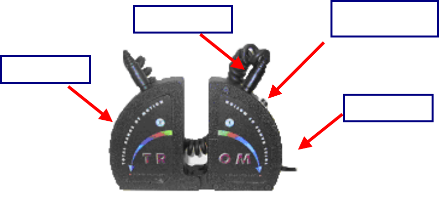
148
The BTE Dual Inclinometers
The dual inclinometers are used to evaluate spinal range of motion, which allows for sections to be tested
in isolation. You may choose to use a single inclinometer; however, the evaluator must be aware of the
value's origin. For example, if you were to assess lumbosacral flexion by placing a single inclinometer on
the appropriate landmark and have the client flexing from a standing position, the inclinometer will
measure the combined lumbosacral and hip flexion.
The single inclinometer can be used to evaluate range of motion of the extremities. The small goniometer
feature can be used to evaluate the range of motion of the smaller joints in the hand and foot.
The basic premise of the dual inclinometers function is to calculate the amount of rotational displacement
of both the sensors and subtract (or add) the two values to arrive at a true range of motion value.
Components
The dual inclinometers consist of three separate components. First, there are two sensors, referred to as
the Master and Remote sensors. There are also two cords that accompany the BTE Dual Inclinometers.
A Foot Pedal is also available to start and stop measurements using the Inclinometer.
One cord connects the Master and Remote sensors together to allow the calculation of angular
displacements. The ends of this cord connect to the ports at the top of each sensor. The other cord is
permanently attached to the Master sensor at one end and fits into the BTE Data Acquisition Box at the
other end. This cord functions to direct all calculated angles into the ODES diagnostic software system.
The BTE Dual Inclinometers are self-calibrating and never need to be manually calibrated.
The Dual inclinometers are connected to the Data Acquisition Box by a long cord from the Master sensor,
which connects to PORT 12 on the Data Acquisition Box.
When using the BTE Dual Inclinometers to measure range of motion, they must always be positioned in
the same plane and with the hinges facing each other. The following figures demonstrate correct and
incorrect orientation for the Dual Inclinometer placement.
Master Sensor
Remote Sensor
Connecting Cable Button to start
measurement
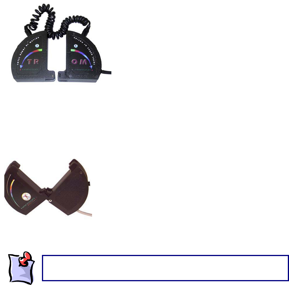
149
The Master sensor has a round black button at its top. When performing a test, this button is pressed at
the start and end of a test range. The difference between the two readings is calculated and entered into
the ODES diagnostic software system. The Inclinometers will not measure accurately if the hinges are at
opposite ends as in this picture. As well the Inclinometers cannot operate in the coronal plane of
movement.
The BTE Dual Inclinometers can also be used as a Small Goniometer when they are attached to each
other. The Dual Inclinometers can be joined to each other as demonstrated in the figure below.
The Master and Remote sensors attach at their bottom corners,
where they form right angles.
When attached, the Dual Inclinometers can be used as a Small
Goniometer to measure finger and thumb range of motion.
To start measuring using the Inclinometers click on the button on the Master or on the foot pedal. To stop
taking the measurement click once again.
The Master and Remote sensors of the Dual Inclinometers have internal magnets. As a
result, it is strongly suggested that these are NOT placed on computer hard drives, since
doin
g
so ma
y
result in erasure of data files!
150
Performing Spinal Range of Motion Evaluations
Following is a table of landmarks for spinal evaluations:
Area to be
Assessed
Superior
Landmark
Inferior
Landmark
Cervical Spine Occiput T1
Thoracic Spine T1 T12
Lumbosacral Spine T12 Sacral Midpoint
Sacral/Hip Flexion/Extension Sacral midpoint Lateral Thigh
Gross Combined hip and spinal flexion/extension T1 Sacral Midpoint
Straight Leg Raise -- Not Applicable -- Anterior Lower Leg
Guidelines to Locating The Landmarks
Occiput - Locate the Occipital protuberance and place the lowest portion of the Inclinometer directly
above it.
T1 - This is usually the larger of the two protruding spinous processes at the base of the cervical spine
near the height of the shoulders. It is easily identified when the client flexes their cervical spine.
T12 - Follow the lower ribs posteriorly to the spinous process.
Sacral Midpoint Follow the iliac crests posteriorly to the PSIS, medially into the sacral sulcus and then
medially to the midline. While maintaining one hand at the midline at this level, locate the sacrococcygeal
joint. Now locate the midpoint between these two landmarks.
Lateral Thigh-Locate the Greater Tuberosity and place the tip of the Inclinometer just inferior.
Anterior Lower Leg-Locate the Tibial Tubercle and follow the anterior ridge of the tibia inferiorly
approximately two-thirds down the lower leg.
For Single Unit Use-Place distally to the joint being assessed in the plane of movement. If there is
compound joint movement use the Dual Inclinometer method of landmarking.
For Dual Unit Use-Place one unit distally and one unit proximally to the joint being assessed, ensuring to
not include the other joint(s) that are involved in the compound movement. Align the sensors in the plane
of movement.
Most importantly, in order to do effective range of motion evaluations with consistency,
ensure that the same landmarks are used each time.
It is important to have the client wear appropriate clothing that exposes, or provides for,
easy access to the landmarks. You may wish to stock such items as cloth or paper client
g
owns for this reason.