BTE Technologies DAQRETROFIT Strength measurement equipment. User Manual 40050053 rev A
BTE Technologies, Inc. Strength measurement equipment. 40050053 rev A
Contents
- 1. FCC Manual Addendum
- 2. Users Manual 1
- 3. Users Manual 2
Users Manual 2
151
These are only guidelines and in most cases these landmarks will work without any problems. However,
there are clients who do have anomalies from birth or from injury that may make landmarking in this way
difficult. In these cases, document any known anomaly discovered in the process of landmarking so that
it may be duplicated for accurate comparison.
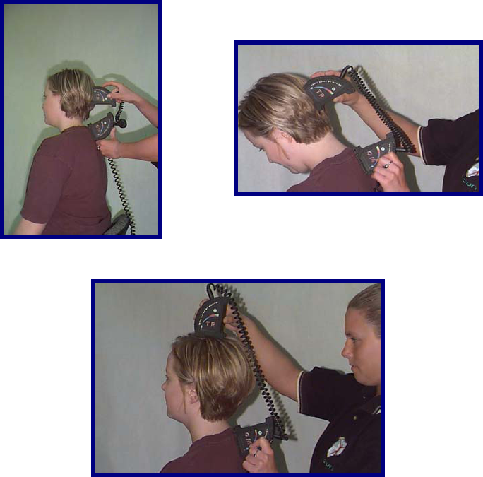
Cervical Range of Motion
Flexion
With the client in a seated position, manually landmark the T1 spinous process using a washable marker.
Align the sensors in the sagittal plane and place one of the Inclinometers on the T1 spinous process.
Place the other over the calvarium. Take the initial reading. Have the client maximally flex the head.
Take the final reading.Return the client to a neutral position and repeat these steps two more times.
Alternatively, the evaluator may place the Inclinometer on top of the head.
152
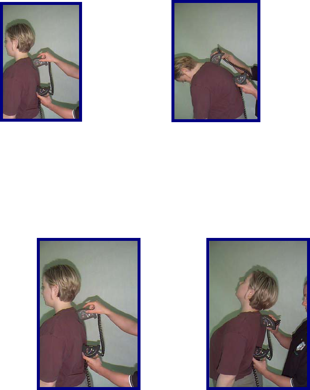
Extension
With the client in a seated position, manually landmark the T1 spinous process using a washable marker.
Align the sensors in the sagittal plane and place one of the Inclinometers laterally on the T1 spinous
process. Place the other over the calvarium. Take the initial reading. Have the client maximally extend
the head. Take the final reading. Return the client to a neutral position and repeat these steps two more
times.
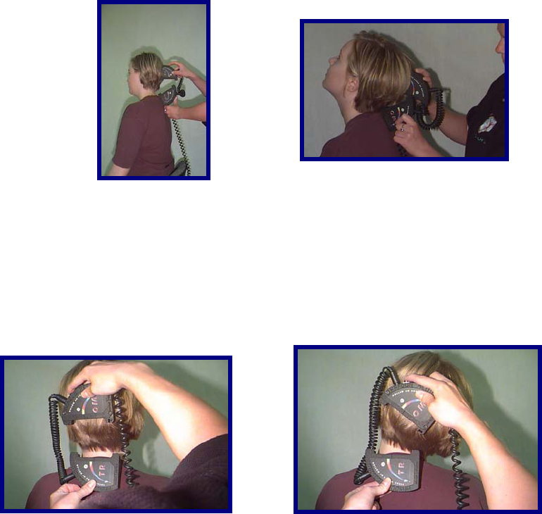
Lateral Flexion
With the client in a seated position, manually landmark the T1 spinous process using a washable marker.
Align the sensors in the coronal plane and place one of the Inclinometers laterally on the T1 spinous
process. Place the other over the calvarium. Take the initial reading. Have the client maximally laterally
flex the head to one side. Take the final reading. Return the client to a neutral position. Repeat these
steps two more times to the same side and then repeat 3 times to the opposite side.
Alternatively the superior, or upper-most Inclinometer may be placed on the top of the head.
153
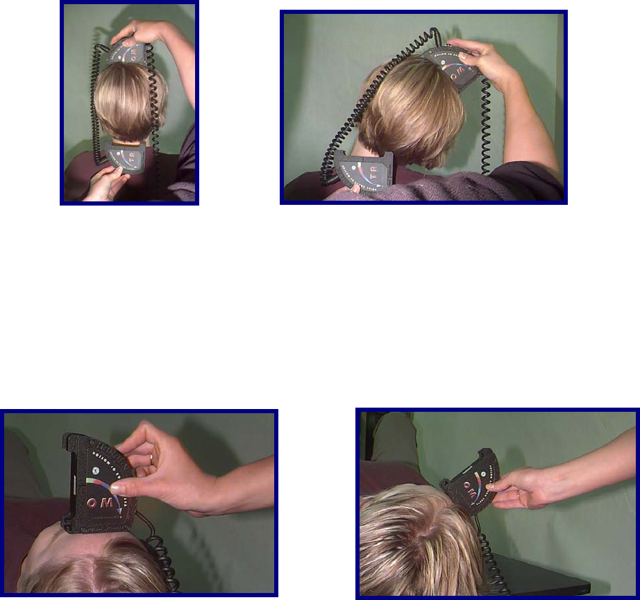
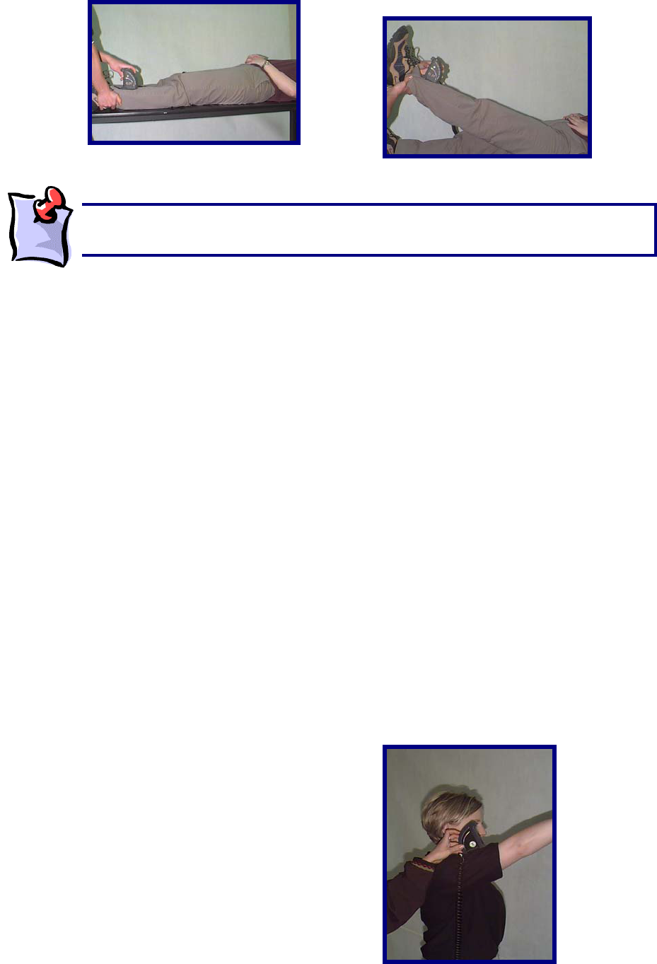
Rotation
Only with cervical rotation do you use a single Inclinometer. Have the client lie in a supine position (this
will stabilize the client's shoulders). The shoulders should be exposed, to allow the evaluator to note
excessive shoulder rotation. Align the sensor in the transverse plane and place the Inclinometer at the
superior portion of the head. Take the initial reading. Have the client maximally rotate their head to one
side. Take the final reading. Return the client to a neutral position. Repeat these steps two more times to
the same side and then repeat 3 times to the opposite side.
Thoracic Range of Motion
Since thoracic is quite dependent on the individual's posture, it is best to have the client use a military
type stance. This will minimize the client's kyphosis.
154
Flexion
With the client in a seated or standing position, manually landmark the T1 and T12 spinous processes
using a washable marker. Align the sensors in the sagittal plane and place one of the Inclinometers on
the T1 spinous process. Place the other at the T12 Spinous Process. Take the initial reading. Have the
client maximally flex the thoracic spine. Take the final reading. Return the client to a neutral position and
repeat these steps two more times.
Minimal Kyphosis
With the client in a seated or standing position, manually landmark the T1 and T12 spinous processes
using a washable marker. Align the sensors in the sagittal plane. Take the initial reading by zeroing the
Inclinometers against a true vertical surface such as a wall, then place one of the Inclinometers on the T1
spinous process. Place the other on the T12 Spinous Process. Take the final reading. Return the client to
a neutral position and repeat these steps two more times.
Rotation
With the client in a standing position, instruct them to forward flex until the thoracic spine is in as
horizontal a position as possible. Manually landmark the T1 and T12 spinous processes using a
washable marker. Aligning the sensors in the axial and vertical planes, place one of the Inclinometers on
the T1 spinous process and place the other at the T12 Spinous Process. Take the initial reading. Have
the client maximally rotate the thoracic spine to one side. Take the final reading. Return the client to a
neutral position. Repeat these steps two more times to the same side and then repeat 3 times to the
opposite side.
155
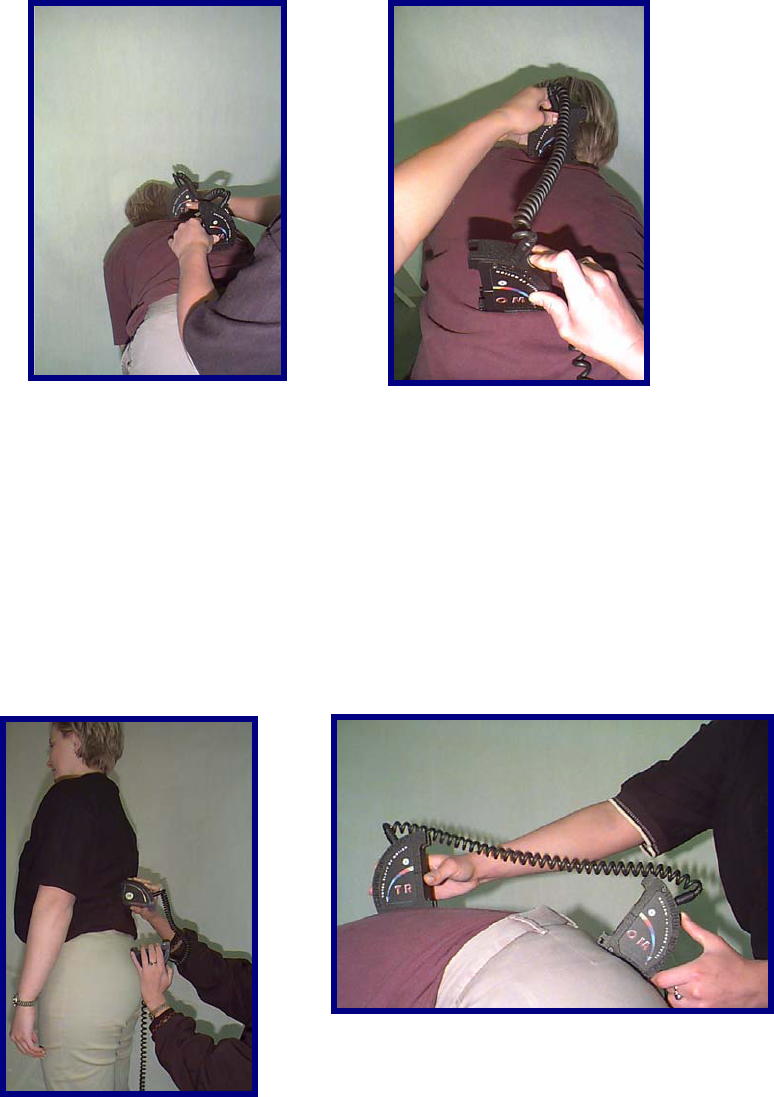
Lumbosacral Range of Motion
Flexion
With the client in a standing position, manually landmark the T12 spinous process using a washable
marker. Align the sensors in the sagittal plane and place one of the Inclinometers on the T12 spinous
process. Place the other at S1 spinous process. Take the initial reading. Have the client maximally flex
the lumbar spine. Take the final reading. Return the client to a neutral position and repeat these steps
two more times.
Extension
With the client in a standing position, manually landmark the T12 spinous process using a washable
marker. Align the sensors in the sagittal plane and place one of the Inclinometers on the T12 spinous
process. Place the other at S1 spinous process. Take the initial reading. Have the client maximally
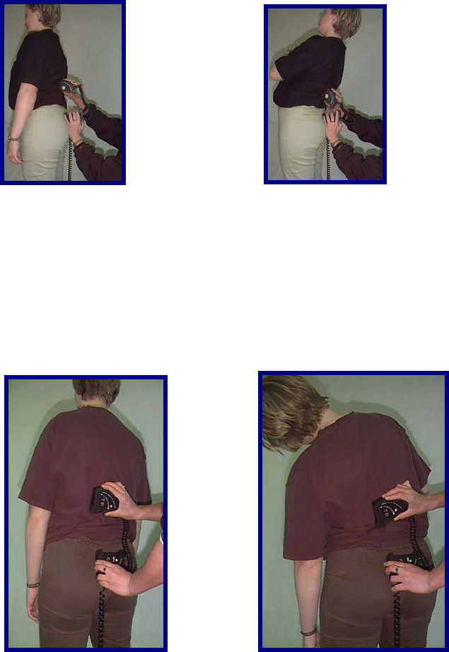
156
extend the lumbar spine. Take the final reading. Return the client to a neutral position and repeat these
steps two more times.
Lateral Flexion
With the client in a standing position, manually landmark the T12 spinous process using a washable
marker. Aligning the sensors in the coronal plane, place one of the Inclinometers on the T12 spinous
process and place the other at the sacral midpoint. Take the initial reading. Have the client maximally
laterally flex the lumbar spine to one side. Take the final reading. Return the client to a neutral position.
Repeat these steps two more times to the same side and then repeat 3 times to the opposite side.
Straight Leg Raise
Have the client lie in a supine position. Aligning the Master sensor in the sagittal plane, place it along the
anterior lower third of the tibia. Take the initial reading. Perform a straight leg raise. Take the final
reading at the end range. Return the client's leg to the resting position and repeat these steps two more
times.
157
Determining the Degree of Ankylosis
When the degree of ankylosis needs to be documented, the steps listed above must be slightly adjusted.
The first reading should be taken against a wall or on a tabletop.
Next, place the client in as close to a neutral position as possible.
Place the two Inclinometers at the appropriate landmarks.
Then take the second reading. This is the degree of ankylosis.
Performing Extremity Range of Motion Evaluations
While ideally the integrated goniometer would be used for the larger extremity joints, the dual or single
Inclinometer method may also be used to assess them.
Below are some examples that may be applied to any of the larger extremity joints.
Shoulder Flexion
With the client in a standing position, manually landmark the lateral upper arm. Using only the Master
sensor, align it in the sagittal plane. Click the button on the Master sensor to take the initial reading. Have
the client maximally flex the shoulder. Click the button on the Master sensor a second time to take the
final reading. ODES will automatically document the final true range. Return the client's shoulder to the
neutral position. Repeat these steps two more times on the same side and then repeat 3 times for the
other side.
The straight leg raise on the tightest side should be within 10 degrees of the total hip
motion (i.e. hip flexion + hip extension).
158
Elbow Flexion
With the client in a standing position, manually landmark the lateral forearm with the hand in a supinated
position. Using only the Master sensor, align it in the sagittal plane. Click the button on the Master sensor
to take the initial reading. Have the client maximally flex the elbow. Click the button on the Master sensor
a second time to take the final reading. ODES will automatically document the final true range. Return the
client's elbow to the neutral position. Repeat these steps two more times on the same side and then
repeat 3 times for the other side.
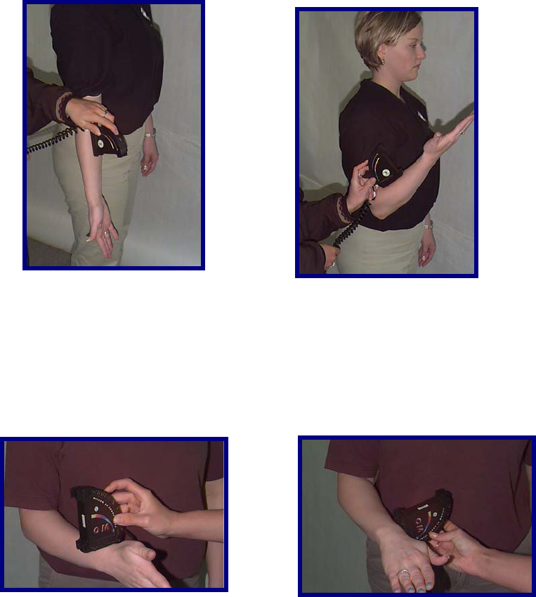
Wrist Pronation
With the client in a standing position, manually landmark the distal radial head with the wrist in a neutral
position. Using only the Master sensor, align it in the coronal plane. Click the button on the Master sensor
to take the initial reading. Have the client maximally pronate the wrist. Click the button on the Master
sensor a second time to take the final reading. ODES will automatically document the final true range.
Return the client's wrist to the neutral position. Repeat these steps two more times on the same side and
then repeat 3 times for the other side.
159
Using the Small Goniometer Feature
When assessing motion in the smaller joints of the digits in the hand or foot, the Dual Inclinometers may
be interlocked to form a small goniometer.
Once interlocked tight together they form a perfectly level and zeroed surface. As with the landmarking
instructions above, place the goniometer so that one Inclinometer is on the proximal side and the other on
the distal side of the joint being assessed.
Digit Ankylosis
If there is joint ankylosis that is to be documented, the following steps are required to obtain the
measurement.
The first reading should be taken with the goniometer interlocked and placed against a wall or on a
tabletop. Next place the client's joint in as close to a neutral position as possible. Place the inclinometer
appropriately, then take the second reading. This is the degree of ankylosis.
Digit Range of Motion Evaluation
To document small digit range of motion, manually landmark the joint being assessed proximally and
distally while in a neutral position, with the client in a seated or lying position. Align the sensors in the
plane of movement (generally sagittal) and position the Inclinometers. Click the button on the master
sensor to take the initial reading. Have the client maximally flex (or extend / abduct / adduct / etc. as the
case requires) the digit. Click the button on the Master sensor a second time to take the final reading.
ODES will automatically document the final true range. Return the client's digit to the neutral position.
Repeat these steps two more times on the same side and then repeat 3 times for the other side.
160
The BTE Goniometer
The goniometer calculates the amount of displacement in degrees to arrive at a true range of motion
value. The goniometer is used to evaluate extremity range of motion. The large goniometer setup may
also be used to evaluate range of motion of the large joints, such as the knee, hip and shoulder. The
small goniometer setup can be used to evaluate the range of motion of the smaller joints in the hand and
foot.
When performing impairment evaluations, the American Medical Association states that the goniometer is
necessary for evaluating the extremities.
Components of the Goniometer
The goniometer includes the long and short arms as well as a foot pedal.
The BTE Goniometer is self-calibrating and never needs to be manually calibrated.
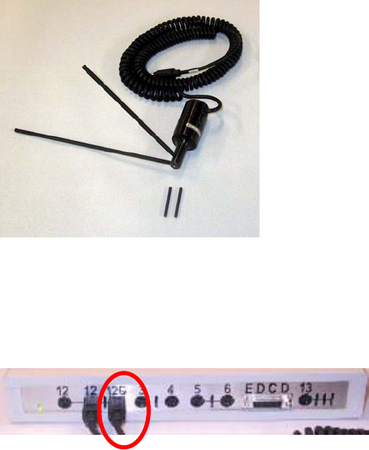
Connecting the Goniometer
The goniometer is connected to the Data Acquisition Device via PORT 12G.
Once the goniometer is connected properly, the red light on the base of the device will light up. See
below.

161
To connect the Foot Pedal, locate the FP port on the back of your Data Acquisition Device. To utilize the
Foot Pedal, attach its cord to the FP port.
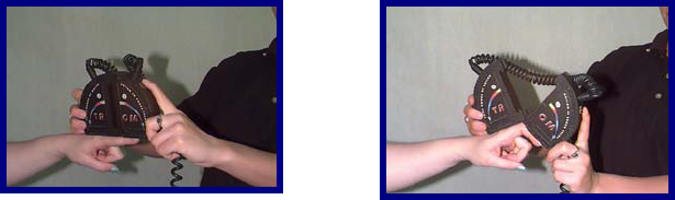
Connecting and Disconnecting the Goniometer Arms:
The small and large goniometer arms can be easily removed from the device. Simply hold the
goniometer in one hand and gently twist the arm off of the device.
Once removed, the goniometer will appear as follows:
Performing Range of Motion Tests
The following is an example of how to perform a Pre-Programmed Range of Motion Protocol
162
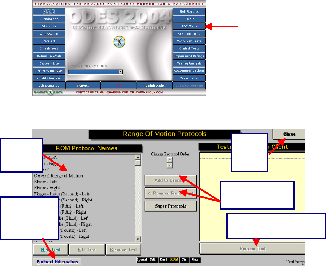
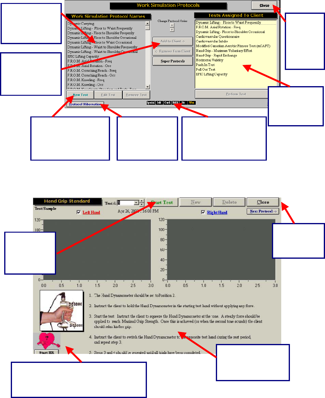
From the ODES home page, click on ROM Test. This will bring you to the Range of Motion Test page.
From here, you have access to all of the pre-programmed tests. You can add tests to clients, create new
custom range of motion tests, edit tests and delete tests.
Available
protocols
are listed
here
Allows you to add and
remove protocols from
your client
Allows you to
move protocols,
which aren’t being
used, into a
temporary folder
Allows
you to
return to
the main
menu
Once a protocol has been
selected, you can click here to
p
erform the test
163
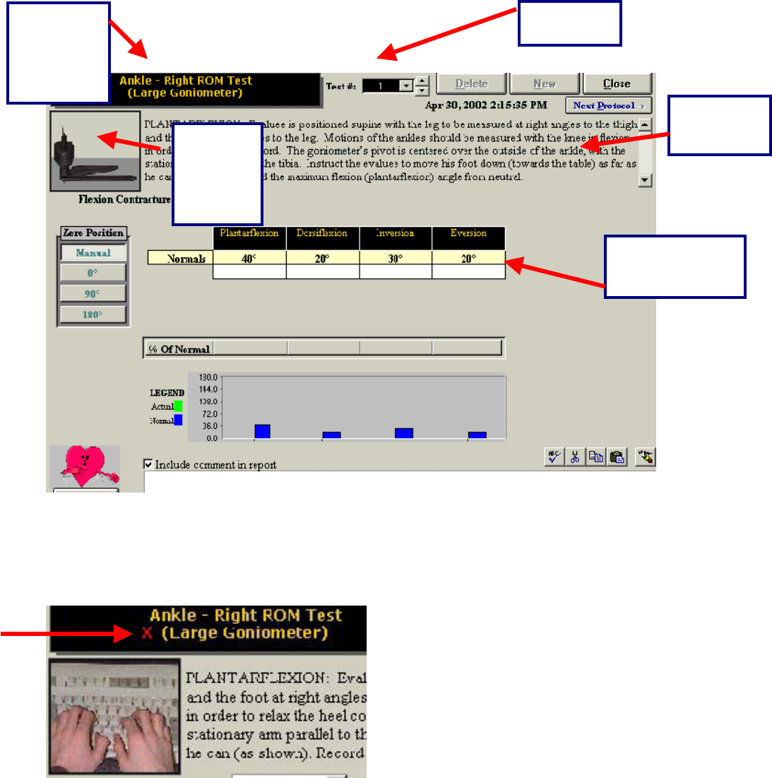
Once you have chosen a test, the following testing page appears:
If the device that you wish to use is not connected properly, or if the DAC box is not communicating with
your computer, you will not be able to perform the test. If this is the case, a red ‘X’ will appear beside the
name of the tool you wish to utilize and the picture of the tool will appear as a keyboard. If this happens,
please see the trouble shooting section of this manual.
If the wrong tool appears in the upper left-hand corner of the screen (for example, the dual inclinometers
instead of the goniometer), double click on the name of the tool. This allows you to alternate between the
two range of motion tools.
Shows the
test name
and device
being
utilized
Shows Test
Number
Lists
protocol
instructons
Device
being
used to
record
readings
Test results are
recorded in these
fields
164
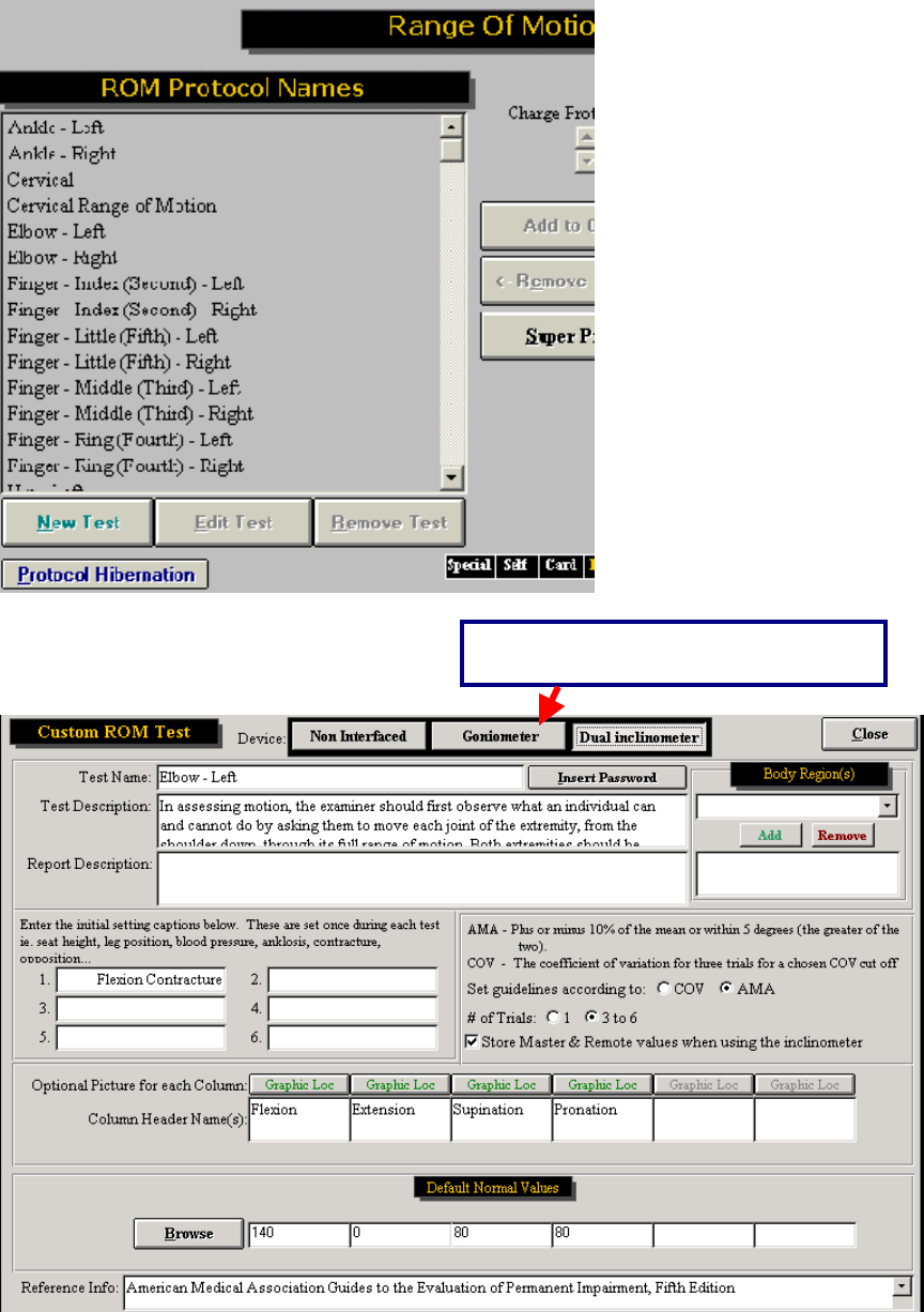
Customizing the Goniometer Tests
In addition to alternating between testing tools, the range of motion testing screen allows you to test in an
AMA or COV format, utilize 1 or 3 trials for each movement, and it allows you to include additional initial
settings that you may wish to note.
Changing From AMA to COV Format
In order to change from AMA to COV format, you must first go into the Range of Motion Protocols page.
Click ROM Test from the ODES main menu.
Highlight the test you wish to modify and then click Edit.
Double click
here to
switch tools
165
The following page will appear:
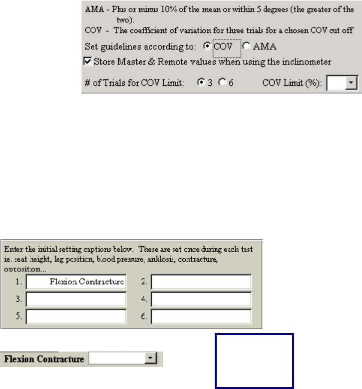
To switch between COV and AMA, use the ‘Set guidelines’ radio buttons. The American Medical
Association (AMA) guidelines indicate a range of motion test is valid if the measurement is within 5
Shows which tool is set as the default
166
degrees or within 10% of each other. Coefficient of Variance (COV) is a statistical measurement. The
current research indicates that a COV 15% or greater is an indication of invalid effort.
You can also modify the number of trials from this page. Just select how many trials you wish to have (1
or 3-6).
Entering In Additional Settings:
In order to modify the initial settings, open the Edit Test page for the test that you wish to modify. This
can be done by going to ROM Test | Edit Test from the ODES main menu. Enter the name of the setting
in one of the white fields (as shown below) and the setting will now appear on your testing page for that
test.
Appears as
an option on
your testing
screen
167
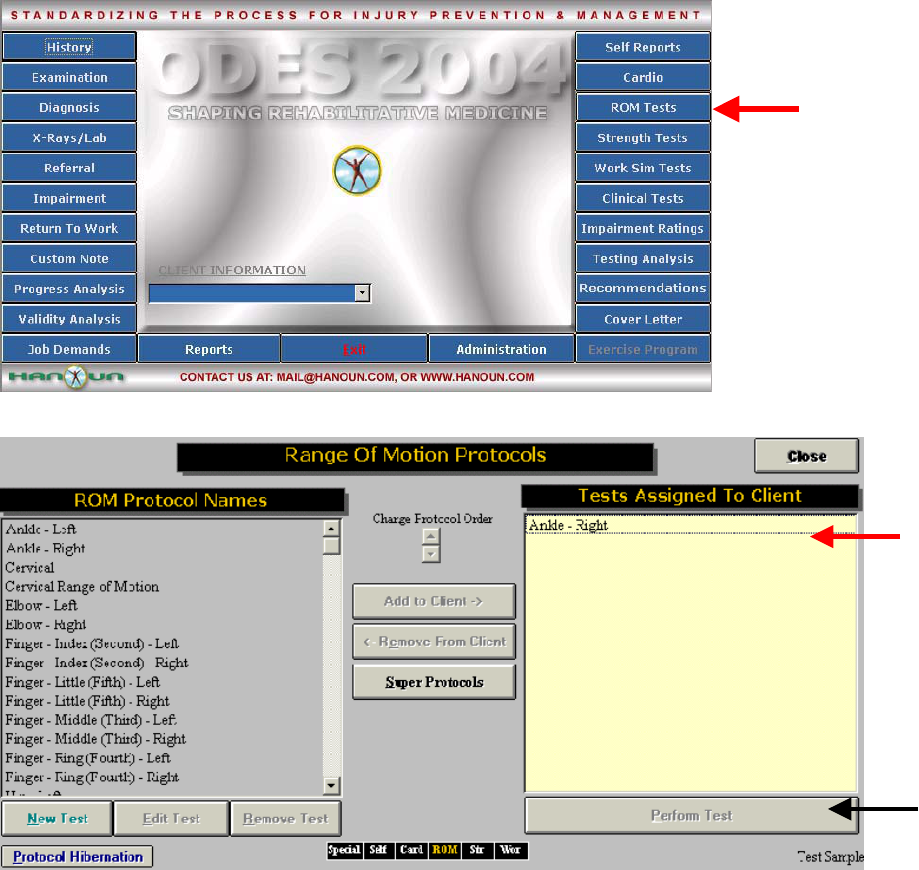
Performing a Range of Motion Test with the Goniometer
From the ODES main menu, you must first select or create a client. You will then be able to click ROM
Test to enter the Range of Motion Protocols page.
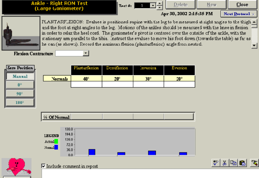
Highlight the test that you wish to perform (in this case, right ankle range of motion has been selected).
In order to add the protocol to your client, click Add to Client. You will now see you’re the selected test
appear in the ‘Test Assigned to Client’ box. To perform this test you may either double-click on the
protocol name, or highlight it and click Perform Test.
The testing page for the selected protocol will be displayed. In order to begin a test, make sure that the
correct tool is listed in the upper left-hand corner of the testing page (underneath the protocol name). In
order to perform the test make sure that your cursor is flashing in the space beside Trial #1.
168
You may now begin testing with your goniometer. Press the red button located on the bottom of the
device or depress the foot pedal to begin and end each trial. The computer will prompt you during each
reading.
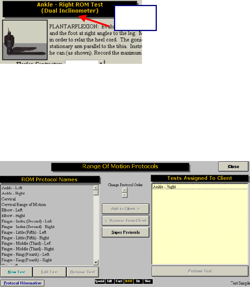
Range of Motion Protocols
The following are the protocols for range of movement as outlined in the ODES software.
Ankle
PLANTARFLEXION: Client is sitting with the leg to be measured at right angles to the thigh and the foot
at right angles to the leg. Motions of the ankles should be measured with the knee at 45 degree flexion in
order to relax the heel cord. The goniometer’s pivot is centered over the outside of the ankle, with the
stationary arm parallel to the tibia. Instruct the client to move their foot down (away from their body) as far
as they can. Record the maximum flexion (plantar flexion) angle from neutral.
FLEXION CONTRACTURE: Flexion contracture is a measure of limited ROM due to muscle contracture.
If the client is capable of both plantar flexion and extension (dorsiflexion), do not measure flexion
contracture. Otherwise, client should be sitting, with the leg to be measured at right angles to the thigh
and the foot at right angles to the leg. Instruct the client to relax the ankle so that it is in its own natural
neutral position. The goniometer’s pivot is centered over the outside of the ankle, with the stationary arm
parallel to the tibia. Record the flexion contracture angle.
DORSIFLEXION: Client is sitting with the leg to be measured at right angles to the thigh and the foot at
right angles to the leg. Motions of the ankles should be measured with the knee in flexion in order to
relax the heel cord. The goniometer’s pivot is centered over the outside of the ankle, with the stationary
169
arm parallel to the tibia. Instruct the client to pull their foot back, towards their body, as far as they can.
Record the maximum extension (dorsiflexion) angle from neutral.
INVERSION: The client should be seated, with the bottom of the foot to be measured parallel to the floor.
(Note: If the foot cannot be placed in this 0-degree neutral position, consider rating ankylosis instead of
range of motion). The goniometer’s pivot is centered over the back of the heel, with the stationary arm
parallel to the tibia. Instruct the client to invert the foot as far as they can. Record the maximum
inversion angle.
EVERSION: The client should be seated, with the bottom of the foot to be measured parallel to the floor.
(Note: If the foot cannot be placed in this 0-degree neutral position, consider rating ankylosis instead of
range of motion). The goniometer’s pivot is centered over the back of the heel, with the stationary arm
parallel to the tibia. Instruct the client to evert the foot as far as they can. Record the maximum eversion
angle.
Knee
FLEXION: The client should be lying supine with the goniometer next to the knee joint; one arm of the
goniometer is parallel to the lower leg, and the other is parallel to the femur. Record the maximum flexion
angle from the starting point.
FLEXION CONTRACTURE: Measuring flexion contracture is similar to measuring ankylosis of the knee in
flexion/extension. The client should be lying supine with the goniometer next to the knee joint; one arm of
the goniometer is parallel to the lower leg, and the other is parallel to the femur. Record any deviation
from 0-degrees.
EXTENSION: The client should be lying supine with the goniometer next to the knee joint; one arm of the
goniometer is parallel to the lower leg and the other is parallel to the femur. Record the maximum
extension angle from the starting point.
Hip
FLEXION: The client is supine on a firm, flat surface with the opposite joint (the hip that is not being
measured) held in flexion until the lumbar spine is flat. (Note: If hip flexion contracture is present, do not
measure it at this time.) Place the goniometer’s pivot at the outside of the hip to be measured. One arm
of the goniometer is parallel to the opposite flexed leg and the other parallel to the femur. The evaluator
should place one hand on the iliac crest to note the point at which the pelvis begins to rotate. Record the
maximum flexion angle.
EXTENSION: The client is prone on a firm, flat surface. Place the goniometer’s pivot at the outside of the
hip to be measured. One arm of the goniometer is parallel to the opposite extended leg and the other is
parallel to the femur of the leg being measured. Record the maximum extension angle.
FLEXION CONTRACTURE: To measure loss of extension of one hip, the contralateral hip if flexed until
the lumbar spine is flat on the examining table, as determined by the evaluator’s hand, which is placed
between the lumbar spine and table surface. The thigh to be measured should rest flat on the table; and
hip flexion is recorded as flexion contracture. (Note: If the client can extend the hip back to or beyond the
neutral position, do not record flexion contracture.)
INTERNAL ROTATION: The client should be lying prone, the knee flexed 90-degrees, with the thigh
perpendicular to the transverse line across the anterior superior spines of the pelvis. The stationary arm
of the goniometer is parallel to the flat surface, and the other is along the tibia. Instruct the client to rotate
the leg away from the midline of the trunk with the thigh as the axis of rotation, thus producing inward
rotation of the hip. Record the maximum internal rotation angle.
170
EXTERNAL ROTATION: The client should be lying supine, the knee flexed 90-degrees, with the thigh
perpendicular to the transverse line across the anterior superior spines of the pelvis. The stationary arm
of the goniometer is parallel to the flat surface, and the other is along the tibia. Instruct the client to rotate
the leg toward the midline of the trunk with the thigh as the axis of rotation, thus producing outward
rotation of the hip. Record the maximum external rotation angle.
ABDUCTION: (Note: If the client has limited motion due to abduction contracture, do not measure
abduction.) The client should be lying supine on a flat surface with the leg to be measured extended at a
right angle to a transverse line across the anterior superior spines of the pelvis. The contralateral hip
should be passively held in flexion. The outward motion of the extremity is measured from the starting
position. Record the maximum abduction angle.
ADDUCTION: (Note: If the client has limited motion due to adduction contracture, do not measure
adduction.) The client should be lying supine on a flat surface with the leg to be measured extended at a
right angle to a transverse line across the anterior superior spines of the pelvis. The contralateral hip
should be passively held in flexion. In measuring adduction, the evaluator should ensure adequate
elevation of the opposite extremity to allow the leg to pass under it.
ABDUCTION CONTRACTURE: The client should be lying supine on a flat surface with the leg to be
measured extended at a right angle to a transverse line across the anterior superior spines of the pelvis.
The contralateral hip should be passively held in flexion. The outward motion of the extremity is
measured from the starting position. Record the smallest abduction contracture angle.
Great Toe
MP EXTENSION: The client is in a seated position. The knee is flexed to 45-degrees and the ankle and
Metatarsophalangeal (MTP) joint are in the neutral position. The small goniometer is placed under the
MTP joint, and its angle is read as a baseline. The client extends (dorsiflexes) the toe maximally, and the
angle subtending the maximum arc of motion is read. Subtract the baseline angle and record the angle of
MP extension.
MP FLEXION: The client is in a seated position. The knee is flexed to 45-degrees and the foot and
Metatarsophalangeal (MTP) joint are in the neutral position. The small goniometer is placed over the
MTP joint, and its angle is read as a baseline. The client flexes (plantarflexes) the toe maximally, and the
angle subtending the maximum arc of motion is read. Subtract the baseline angle and record the angle of
MP flexion.
IP FLEXION: The client is in a seated position. The knee is flexed to 45-degrees and the ankle and
Interphalangeal (IP) joint are in the neutral position. The small goniometer is placed over the IP joint, and
its angle is read as a baseline. The client flexes (plantarflexes) the toe maximally, and the angle
subtending the maximum arc of motion is read. Subtract the baseline angle and record the angle of IP
flexion.
Lesser 2 Toe
MP FLEXION: The client is in a seated position. The knee is flexed to 45-degrees and the ankle and
Metatarsophalangeal (MTP) joint are in the neutral position. The small goniometer is placed over the
MTP joint, and its angle is read as a baseline. The client flexes (plantarflexes) the toe maximally, and the
angle subtending the maximum arc of motion is read. Subtract the baseline angle and record the angle of
MP flexion.
MP EXTENSION: The client is in a seated position. The knee is flexed to 45-degrees and the ankle and
Metatarsophalangeal (MTP) joint are in the neutral position. The small goniometer is placed under the
171
MTP joint, and its angle is read as a baseline. The client extends (dorsiflexes) the toe maximally, and the
angle subtending the maximum arc of motion is read. Subtract the baseline angle and record the angle of
MP extension.
IP FLEXION: The client is in a seated position. The knee is flexed to 45-degrees and the ankle and
Metatarsophalangeal (MTP) joint are in the neutral position. The small goniometer is placed over the
MTP joint, and its angle is read as a baseline. The client flexes (plantarflexes) the toe maximally, and the
angle subtending the maximum arc of motion is read. Subtract the baseline angle and record the angle of
MP flexion.
IP EXTENSION: The client is in a seated position. The knee is flexed to 45-degrees and the ankle and
Metatarsophalangeal (MTP) joint are in the neutral position. The small goniometer is placed under the
MTP joint, and its angle is read as a baseline. The client extends (dorsiflexes) the toe maximally, and the
angle subtending the maximum arc of motion is read. Subtract the baseline angle and record the angle of
MP extension.
Toe Lesser 4
MP FLEXION: The client is in a seated position. The knee is flexed to 45-degrees and the ankle and
Metatarsophalangeal (MTP) joint are in the neutral position. The small goniometer is placed over the
MTP joint, and its angle is read as a baseline. The client flexes (plantarflexes) the toe maximally, and the
angle subtending the maximum arc of motion is read. Subtract the baseline angle and record the angle of
MP flexion.
MP EXTENSION: The client is in a seated position. The knee is flexed to 45-degrees and the ankle and
Metatarsophalangeal (MTP) joint are in the neutral position. The small goniometer is placed under the
MTP joint, and its angle is read as a baseline. The client extends (dorsiflexes) the toe maximally, and the
angle subtending the maximum arc of motion is read. Subtract the baseline angle and record the angle of
MP extension.
IP Extension: The client is in a seated position. The knee is flexed to 45-degrees and the ankle and
Metatarsophalangeal (MTP) joint are in the neutral position. The goniometer is placed under the MTP
joint, and its angle is read as a baseline. The client extends (dorsiflexes) the toe maximally, and the
angle subtending the maximum arc of motion is read. Subtract the baseline angle and record the angle of
MP extension.
Toe Lesser 5
MP FLEXION: The client is in a seated position. The knee is flexed to 45-degrees and the ankle and
Metatarsophalangeal (MTP) joint are in the neutral position. The small goniometer is placed over the
MTP joint, and its angle is read as a baseline. The client flexes (plantarflexes) the toe maximally, and the
angle subtending the maximum arc of motion is read. Subtract the baseline angle and record the angle of
MP flexion.
MP EXTENSTION: The client is in a seated position. The knee is flexed to 45-degrees and the ankle and
Metatarsophalangeal (MTP) joint are in the neutral position. The goniometer is placed under the MTP
joint, and its angle is read as a baseline. The client extends (dorsiflexes) the toe maximally, and the
angle subtending the maximum arc of motion is read. Subtract the baseline angle and record the angle of
MP extension.
Shoulder
In assessing motion, the examiner should first observe what an individual can and cannot do by asking
them to move each joint of the extremity, from the shoulder down, through its full range of motion. Both
172
extremities should be compared. Individual joints are then evaluated separately. In determining the range
of motion of individual joints, the examiner must evaluate both the active and passive motion.
FLEXION: The client should be standing erect, with the arm to be measured at the side of the body. Place
the goniometer’s pivot on the outside of the shoulder joint to be measured with the stationary arm
perpendicular to the ground. The movable arm will remain parallel to the humerus. Instruct the client to
move the arm in a forward upward motion in the anterior sagittal plane of the body. Record the maximum
forward flexion angle.
EXTENSION: The client should be standing erect, with the arm to be measured at the side of the body.
Place the goniometer’s pivot on the outside of the shoulder joint to be measured with the stationary arm
perpendicular to the ground. The movable arm will remain parallel to the humerus. Instruct the client to
move the arm in an upward motion in the posterior sagittal plane of the body. Record the maximum
backward extension angle.
ABDUCTION: The client should be standing erect, with the arm to be measured at the side of the body,
palm in. Place the goniometer’s pivot in front of the shoulder joint to be measured with the stationary arm
perpendicular to the ground.; The movable arm will remain parallel to the humerus. Instruct the client to
move the arm in an upward motion away from the side of the body in the coronal plane as far as possible.
Record the maximum abduction angle.
ADDUCTION: The client should be standing erect, with the arm to be measured at the side of the body,
palm in. Place the goniometer’s pivot in front of the shoulder joint to be measured with the stationary arm
perpendicular to the ground. The movable arm will remain parallel to the humerus. Instruct the client to
move the arm toward the midline of the body, and beyond it in an upward plane as far as possible.
Record the maximum adduction angle.
INTERNAL ROTATION: The client should be supine on a flat surface, with the arm to be measured in 90-
degrees of abduction, the elbow in 90-degrees of flexion, and the forearm in neutral. Place the
goniometer’s pivot at approximately the lateral epicondyle with the stationary arm perpendicular to the
floor. The movable arm will remain in alignment with the ulna. Instruct the client to move the arm as far as
possible in a rotational orientation so that the palm goes down, toward the floor. Record the maximum
internal rotation angle.
EXTERNAL ROTATION: The client should be supine on a flat surface, with the arm to be measured in
90-degrees of abduction, the elbow in 90-degrees of flexion, and the forearm in neutral. Place the
goniometer’s pivot at approximately the lateral epicondyle with the stationary arm perpendicular to the
floor. The movable arm will remain in alignment with the ulna. Instruct the client to move the arm as far as
possible in a rotational orientation so that the back of the hand goes back, toward the floor. Record the
maximum external rotation angle.
Elbow
In assessing motion, the examiner should first observe what an individual can and cannot do by asking
them to move each joint of the extremity, from the shoulder down, through its full range of motion. Both
extremities should be compared. Individual joints are then evaluated separately. In determining the range
of motion of individual joints, the examiner must evaluate both the active and passive motion.
FLEXION: The client should be standing with the arm to be measured flexed at the elbow in a forearm
supination, and 90-degrees of shoulder forward flexion. The goniometer’s pivot should be centrally placed
lateral to the lateral epicondyle with the stationary arm in alignment to the lateral aspect/midline of the
humerus, and the movable arm in alignment to the lateral aspect/midline of the radius. Record the
maximum flexion angle.
173
EXTENSION: The client should be standing with the arm to be measured extended at the elbow in
forearm supination, and 90-degrees of shoulder forward flexion. The goniometer’s pivot should be
centrally placed lateral to the lateral epicondyle with the stationary arm in alignment to the lateral
aspect/midline of the humerus, and the movable arm in alignment to the lateral aspect/midline of the
radius. Record the maximum extension angle up to the 0-degree/neutral position.
SUPINATION: The client should be sitting on a flat surface, or standing with the arm to be measured in
midposition with the palm vertical in relation to the floor (“thumbs up” position), with the upper arm close
to the side of the body, and the elbow flexed at 90-degrees. The goniometer’s pivot should be placed
medial to the ulnar styloid process. The stationary arm of the goniometer should be parallel to the anterior
midline of the humerus, and the movable arm across the volar aspect of the forearm, just proximal to the
styloid processes. Instruct the client to turn “palm up” as far as possible. Record the maximum supination
angle.
PRONATION: The client should be sitting on a flat surface, or standing with the forearm to be measured
in midposition with the palm vertical in relation to the floor (“thumbs up” position), with the upper arm close
to the side of the body, and the elbow flexed at 90-degrees. The goniometer’s pivot should be centrally
placed lateral to the ulnar styloid process. The stationary arm of the goniometer should be parallel to the
anterior midline of the humerus, and the movable arm across the dorsal aspect of the forearm just
proximal to the styloid processes of the radius and ulna. Instruct the client to turn “palm down” as far as
possible. Record the maximum pronation angle.
Wrist
In assessing motion, the examiner should first observe what an individual can and cannot do by asking
them to move each joint of the extremity, from the shoulder down, through its full range of motion. Both
extremities should be compared. Individual joints are then evaluated separately. Similarly, movements of
the digits are first evaluated as a unit by having the client make a complete fist, and then individually by
extending the digits fully over several repetitions. In determining the range of motion of individual joints,
the examiner must evaluate both the active and passive motion.
FLEXION: The client should start with the elbow flexed, the forearm positioned in neutral
pronation/supination, and the wrist to be measured in neutral flexion/extension and radioulnar deviation.
The fingers should be relaxed to avoid active finger flexion. The goniometer’s pivot is placed over the
dorsal surface of the wrist joint using the capitate as a reference. Align the stationary arm with the dorsal
midline of the forearm using the lateral epicondyle of the humerus as a reference. Align the movable arm
in between the dorsal heads of the index and middle metacarpals. Record the maximum wrist flexion
angle.
EXTENSION: The client should start with the elbow flexed, the forearm positioned in neutral pronation,
and the wrist to be measured in neutral flexion/extension and radioulnar deviation. The goniometer’s pivot
is placed over the volar surface of the wrist joint at the level of the capitate with the stationary arm in
alignment with the volar midline of the forearm, and the movable arm in between the volar heads of the
index and middle metacarpals. Record the maximum wrist extension angle.
RADIAL DEVIATION: The client should start with the hand to be measured in forearm pronation and the
wrist in neutral flexion/extension and radioulnar deviation. The goniometer’s pivot is placed over the
middle dorsal aspect of the wrist in line with the capitate. Align the stationary arm with the dorsal midline
of the forearm using the lateral epicondyle of the humerus for a reference. Align the moving arm with the
dorsal midline of the third metacarpal. Instruct the client to move the hand towards the thumb in the same
plane as the table. Record the maximum radial deviation angle.
ULNAR DEVIATION: The client should start with the hand to be measured in forearm pronation and the
wrist in neutral flexion/extension and radioulnar deviation. The goniometer’s pivot is placed over the
middle dorsal aspect of the wrist in line with the capitate. Align the stationary arm with the dorsal midline
174
of the forearm using the lateral epicondyle of the humerus for a reference. Align the moving arm with the
dorsal midline of the third metacarpal. Instruct the client to move the hand towards the little finger in the
same plane as the table. Record the maximum ulnar deviation angle.
Thumb
In assessing motion, the examiner should first observe what an individual can and cannot do by asking
them to move each joint of the extremity, from the shoulder down, through its full range of motion. Both
extremities should be compared. Individual joints are then evaluated separately. Similarly, movements of
the digits are first evaluated as a unit by having the client make a complete fist, and then individually by
extending the digits fully over several repetitions. In determining the range of motion of individual joints,
the examiner must evaluate both the active and passive motion.
MP EXTENSION: The client’s hand should be flat on a table with the volar head of the metacarpal
supported at the table’s edge, and neutral wrist flexion/extension and radioulnar deviation. Place the
goniometer’s pivot over the dorsal head of the metacarpophalangeal (MPJ) joint with the stationary arm in
alignment with the dorsal midline of the metacarpal and the movable arm in alignment with the dorsal
midline of the proximal phalanx. Instruct the client to extend, or straighten the MPJ as far as possible.
Record the maximum MP extension angle.
MP FLEXION: The client’s hand should be flat on a table with the volar head of the metacarpal supported
at the table’s edge, neutral wrist flexion/extension and radioulnar deviation. Place the goniometer’s pivot
over the dorsal head of the metacarpophalangeal (MPJ) joint with the stationary arm in alignment with the
dorsal midline of the metacarpal and the movable arm in alignment with the dorsal midline of the proximal
phalanx. Instruct the client to flex the MPJ as far as possible. Record the maximum MP flexion angle.
PIP EXTENSION: The client’s forearm should be pronated, the wrist in neutral flexion/extension and
radioulnar deviation, and the metacarpophalangeal joint in 0-degrees of extension. If possible, place the
hand to be measured flat on a table with the volar head of the proximal phalanx supported at the table’s
edge. Place the goniometer’s pivot over the dorsal head of the proximal interphalangeal joint (PIP) with
the stationary arm in alignment with the proximal phalanx and the movable arm in alignment with the
middle phalanx. Instruct the client to extend, or straighten the PIP joint as far as possible. Record the
maximum PIP extension angle.
PIP FLEXION: The client’s forearm should be pronated, the wrist in neutral flexion/extension and
radioulnar deviation, and the metacarpophalangeal joint in 0-degrees of extension. If possible, place the
hand to be measured flat on a table with the volar head of the proximal phalanx supported at the table’s
edge. Place the goniometer’s pivot over the dorsal head of the proximal interphalangeal joint (PIP) with
the stationary arm in alignment with the dorsal midline of the proximal phalanx and the movable arm in
alignment with the dorsal midline of the middle phalanx. Instruct the client to flex the PIP as far as
possible. Record the maximum PIP flexion angle.
DIP EXTENSION: The client’s forearm should be pronated or in neutral pronation/supination, and the
wrist in neutral flexion/extension and radioulnar deviation. The metacarpophalangeal joint is positioned in
0-degrees of extension and the proximal interphalangeal joint in approximately 70-90 degrees of flexion.
Place the goniometer’s pivot over the dorsal head of the distal interphalangeal joint (DIP) with the
stationary arm in alignment with the dorsal midline of the middle phalanx and the movable arm in
alignment with the distal phalanx. Instruct the client to extend, or straighten the DIP joint as far as
possible. Record the maximum DIP extension angle.
DIP FLEXION: The client’s forearm should be pronated or in neutral pronation/supination, and the wrist in
neutral flexion/extension and radioulnar deviation. The metacarpophalangeal joint is positioned in 0-
degrees of extension and the proximal interphalangeal joint in approximately 70-90 degrees of flexion.
Place the goniometer’s pivot over the dorsal head of the distal interphalangeal joint (DIP) with the
175
stationary arm in alignment with the dorsal midline of the middle phalanx and the movable arm in
alignment with the distal phalanx. Instruct the client to extend, or straighten the DIP joint as far as
possible. Record the maximum DIP extension angle.
Finger Index 2
In assessing motion, the examiner should first observe what an individual can and cannot do by asking
them to move each joint of the extremity, from the shoulder down, through its full range of motion. Both
extremities should be compared. Individual joints are then evaluated separately. Similarly, movements of
the digits are first evaluated as a unit by having the client make a complete fist, and then individually by
extending the digits fully over several repetitions. In determining the range of motion of individual joints,
the examiner must evaluate both the active and passive motion.
EXTENSION: The client’s hand should be flat on a table with the volar head of the metacarpal supported
at the table’s edge, and neutral wrist flexion/extension and radioulnar deviation. Place the goniometer’s
pivot over the dorsal head of the metacarpophalangeal (MPJ) joint with the stationary arm in alignment
with the dorsal midline of the metacarpal and the movable arm in alignment with the dorsal midline of the
proximal phalanx. Instruct the client to extend, or straighten the MPJ as far as possible. Record the
maximum MP extension angle.
FLEXION: The client’s hand should be flat on a table with the volar head of the metacarpal supported at
the table’s edge, and neutral wrist flexion/extension and radioulnar deviation. Place the goniometer’s pivot
over the dorsal head of the metacarpophalangeal (MPJ) joint with the stationary arm in alignment with the
dorsal midline of the metacarpal and the movable arm in alignment with the dorsal midline of the proximal
phalanx. Instruct the client to flex the MPJ as far as possible. Record the maximum MP flexion angle.
PIP EXTENSION: The client’s forearm should be pronated, the wrist in neutral flexion/extension and
radioulnar deviation, and the metacarpophalangeal joint in 0-degrees of extension. If possible, place the
hand to be measured flat on a table with the volar head of the proximal phalanx supported at the table’s
edge. Place the goniometer’s pivot over the dorsal head of the proximal interphalangeal joint (PIP) with
the stationary arm in alignment with the proximal phalanx and the movable arm in alignment with the
middle phalanx. Instruct the client to extend, or straighten the PIP joint as far as possible. Record the
maximum PIP extension angle.
PIP FLEXION: The client’s forearm should be pronated, the wrist in neutral flexion/extension and
radioulnar deviation, and the metacarpophalangeal joint in 0-degrees of extension. If possible, place the
hand to be measured flat on a table with the volar head of the proximal phalanx supported at the table’s
edge. Place the goniometer’s pivot over the dorsal head of the proximal interphalangeal joint (PIP) with
the stationary arm in alignment with the dorsal midline of the proximal phalanx and the movable arm in
alignment with the dorsal midline of the middle phalanx. Instruct the client to flex the PIP as far as
possible. Record the maximum PIP flexion angle.
DIP EXTENSION: The client’s forearm should be pronated or in neutral pronation/supination, and the
wrist in neutral flexion/extension and radioulnar deviation. The metacarpophalangeal joint is positioned in
0-degrees of extension and the proximal interphalangeal joint in approximately 70-90 degrees of flexion.
Place the goniometer’s pivot over the dorsal head of the distal interphalangeal joint (DIP) with the
stationary arm in alignment with the dorsal midline of the middle phalanx and the movable arm in
alignment with the distal phalanx. Instruct the client to extend, or straighten the DIP joint as far as
possible. Record the maximum DIP extension angle.
DIP FLEXION: The client’s forearm should be pronated or in neutral pronation/supination, and the wrist in
neutral flexion/extension and radioulnar deviation. The metacarpophalangeal joint is positioned in 0-
degrees of extension and the proximal interphalangeal joint in approximately 70-90 degrees of flexion.
Place the goniometer’s pivot over the dorsal head of the distal interphalangeal joint (DIP) with the
176
stationary arm in alignment with the dorsal midline of the middle phalanx and the movable arm in
alignment with the distal phalanx. Instruct the client to flex the DIP joint as far as possible. Record the
maximum DIP flexion angle.
Finger Middle 3
In assessing motion, the examiner should first observe what an individual can and cannot do by asking
them to move each joint of the extremity, from the shoulder down, through its full range of motion. Both
extremities should be compared. Individual joints are then evaluated separately. Similarly, movements of
the digits are first evaluated as a unit by having the client make a complete fist, and then individually by
extending the digits fully over several repetitions. In determining the range of motion of individual joints,
the examiner must evaluate both the active and passive motion.
EXTENSION: The client’s hand should be flat on a table with the volar head of the metacarpal supported
at the table’s edge, and neutral wrist flexion/extension and radioulnar deviation. Place the goniometer’s
pivot over the dorsal head of the metacarpophalangeal (MPJ) joint with the stationary arm in alignment
with the dorsal midline of the metacarpal and the movable arm in alignment with the dorsal midline of the
proximal phalanx. Instruct the client to extend, or straighten the MPJ as far as possible. Record the
maximum MP extension angle.
MP FLEXION: The client’s hand should be flat on a table with the volar head of the metacarpal supported
at the table’s edge, and neutral wrist flexion/extension and radioulnar deviation. Place the goniometer’s
pivot over the dorsal head of the metacarpophalangeal (MPJ) joint with the stationary arm in alignment
with the dorsal midline of the metacarpal and the movable arm in alignment with the dorsal midline of the
proximal phalanx. Instruct the client to flex the MPJ as far as possible. Record the maximum MP flexion
angle.
PIP EXTENSION: The client’s forearm should be pronated, the wrist in neutral flexion/extension and
radioulnar deviation, and the metacarpophalangeal joint in 0-degrees of extension. If possible, place the
hand to be measured flat on a table with the volar head of the proximal phalanx supported at the table’s
edge. Place the goniometer’s pivot over the dorsal head of the proximal interphalangeal joint (PIP) with
the stationary arm in alignment with the proximal phalanx and the movable arm in alignment with the
middle phalanx. Instruct the client to extend, or straighten the PIP joint as far as possible. Record the
maximum PIP extension angle.
PIP FLEXION: The client’s forearm should be pronated, the wrist in neutral flexion/extension and
radioulnar deviation, and the metacarpophalangeal joint in 0-degrees of extension. If possible, place the
hand to be measured flat on a table with the volar head of the proximal phalanx supported at the table’s
edge. Place the goniometer’s pivot over the dorsal head of the proximal interphalangeal joint (PIP) with
the stationary arm in alignment with the dorsal midline of the proximal phalanx and the movable arm in
alignment with the dorsal midline of the middle phalanx. Instruct the client to flex the PIP as far as
possible. Record the maximum PIP flexion angle.
DIP EXTENSION: The client’s forearm should be pronated or in neutral pronation/supination, and the
wrist in neutral flexion/extension and radioulnar deviation. The metacarpophalangeal joint is positioned in
0-degrees of extension and the proximal interphalangeal joint in approximately 70-90 degrees of flexion.
Place the goniometer’s pivot over the dorsal head of the distal interphalangeal joint (DIP) with the
stationary arm in alignment with the dorsal midline of the middle phalanx and the movable arm in
alignment with the distal phalanx. Instruct the client to extend, or straighten the DIP joint as far as
possible. Record the maximum DIP extension angle.
DIP FLEXION: The client’s forearm should be pronated or in neutral pronation/supination, and the wrist in
neutral flexion/extension and radioulnar deviation. The metacarpophalangeal joint is positioned in 0-
degrees of extension and the proximal interphalangeal joint in approximately 70-90 degrees of flexion.
177
Place the goniometer’s pivot over the dorsal head of the distal interphalangeal joint (DIP) with the
stationary arm in alignment with the dorsal midline of the middle phalanx and the movable arm in
alignment with the distal phalanx. Instruct the client to extend, or straighten the DIP joint as far as
possible. Record the maximum DIP extension angle.
Finger Ring 4
In assessing motion, the examiner should first observe what an individual can and cannot do by asking
them to move each joint of the extremity, from the shoulder down, through its full range of motion. Both
extremities should be compared. Individual joints are then evaluated separately. Similarly, movements of
the digits are first evaluated as a unit by having the client make a complete fist, and then individually by
extending the digits fully over several repetitions. In determining the range of motion of individual joints,
the examiner must evaluate both the active and passive motion.
EXTENSION: The client’s hand should be flat on a table with the volar head of the metacarpal supported
at the table’s edge, and neutral wrist flexion/extension and radioulnar deviation. Place the goniometer’s
pivot over the dorsal head of the metacarpophalangeal (MPJ) joint with the stationary arm in alignment
with the dorsal midline of the metacarpal and the movable arm in alignment with the dorsal midline of the
proximal phalanx. Instruct the client to extend, or straighten the MPJ as far as possible. Record the
maximum MP extension angle. MP
FLEXION: The client’s hand should be flat on a table with the volar head of the metacarpal supported at
the table’s edge, and neutral wrist flexion/extension and radioulnar deviation. Place the goniometer’s pivot
over the dorsal head of the metacarpophalangeal (MPJ) joint with the stationary arm in alignment with the
dorsal midline of the metacarpal and the movable arm in alignment with the dorsal midline of the proximal
phalanx. Instruct the client to flex the MPJ as far as possible. Record the maximum MP flexion angle.
PIP EXTENSION: The client’s forearm should be pronated, the wrist in neutral flexion/extension and
radioulnar deviation, and the metacarpophalangeal joint in 0-degrees of extension. If possible, place the
hand to be measured flat on a table with the volar head of the proximal phalanx supported at the table’s
edge. Place the goniometer’s pivot over the dorsal head of the proximal interphalangeal joint (PIP) with
the stationary arm in alignment with the proximal phalanx and the movable arm in alignment with the
middle phalanx. Instruct the client to extend, or straighten the PIP joint as far as possible. Record the
maximum PIP extension angle.
PIP FLEXION: The client’s forearm should be pronated, the wrist in neutral flexion/extension and
radioulnar deviation, and the metacarpophalangeal joint in 0-degrees of extension. If possible, place the
hand to be measured flat on a table with the volar head of the proximal phalanx supported at the table’s
edge. Place the goniometer’s pivot over the dorsal head of the proximal interphalangeal joint (PIP) with
the stationary arm in alignment with the dorsal midline of the proximal phalanx and the movable arm in
alignment with the dorsal midline of the middle phalanx. Instruct the client to flex the PIP as far as
possible. Record the maximum PIP flexion angle.
DIP EXTENSION: The client’s forearm should be pronated or in neutral pronation/supination, and the
wrist in neutral flexion/extension and radioulnar deviation. The metacarpophalangeal joint is positioned in
0-degrees of extension and the proximal interphalangeal joint in approximately 70-90 degrees of flexion.
Place the goniometer’s pivot over the dorsal head of the distal interphalangeal joint (DIP) with the
stationary arm in alignment with the dorsal midline of the middle phalanx and the movable arm in
alignment with the distal phalanx. Instruct the client to extend, or straighten the DIP joint as far as
possible. Record the maximum DIP extension angle.
DIP FLEXION: The client’s forearm should be pronated or in neutral pronation/supination, wrist in neutral
flexion/extension and radioulnar deviation. The metacarpophalangeal joint is positioned in 0-degrees of
extension and the proximal interphalangeal joint in approximately 70-90 degrees of flexion. Place the
goniometer’s pivot over the dorsal head of the distal interphalangeal joint (DIP) with the stationary arm in
178
alignment with the dorsal midline of the middle phalanx and the movable arm in alignment with the distal
phalanx. Instruct the client to extend, or straighten the DIP joint as far as possible. Record the maximum
DIP extension angle.
Finger Little 5
In assessing motion, the examiner should first observe what an individual can and cannot do by asking
them to move each joint of the extremity, from the shoulder down, through its full range of motion. Both
extremities should be compared. Individual joints are then evaluated separately. Similarly, movements of
the digits are first evaluated as a unit by having the client make a complete fist, and then individually by
extending the digits fully over several repetitions. In determining the range of motion of individual joints,
the examiner must evaluate both the active and passive motion.
MP EXTENSION: The client’s hand should be flat on a table with the volar head of the metacarpal
supported at the table’s edge, and neutral wrist flexion/extension and radioulnar deviation. Place the
goniometer’s pivot over the dorsal head of the metacarpophalangeal (MPJ) joint with the stationary arm in
alignment with the dorsal midline of the metacarpal and the movable arm in alignment with the dorsal
midline of the proximal phalanx. Instruct the client to extend, or straighten the MPJ as far as possible.
Record the maximum MP extension angle.
MP FLEXION: The client’s hand should be flat on a table with the volar head of the metacarpal supported
at the table’s edge, and neutral wrist flexion/extension and radioulnar deviation. Place the goniometer’s
pivot over the dorsal head of the metacarpophalangeal (MPJ) joint with the stationary arm in alignment
with the dorsal midline of the metacarpal and the movable arm in alignment with the dorsal midline of the
proximal phalanx. Instruct the client to flex the MPJ as far as possible. Record the maximum MP flexion
angle.
PIP EXTENSION: The client’s forearm should be pronated, the wrist in neutral flexion/extension and
radioulnar deviation, and the metacarpophalangeal joint in 0-degrees of extension. If possible, place the
hand to be measured flat on a table with the volar head of the proximal phalanx supported at the table’s
edge. Place the goniometer’s pivot over the dorsal head of the proximal interphalangeal joint (PIP) with
the stationary arm in alignment with the proximal phalanx and the movable arm in alignment with the
middle phalanx. Instruct the client to extend, or straighten the PIP joint as far as possible. Record the
maximum PIP extension angle.
PIP FLEXION: The client’s forearm should be pronated, the wrist in neutral flexion/extension and
radioulnar deviation, and the metacarpophalangeal joint in 0-degrees of extension. If possible, place the
hand to be measured flat on a table with the volar head of the proximal phalanx supported at the table’s
edge. Place the goniometer’s pivot over the dorsal head of the proximal interphalangeal joint (PIP) with
the stationary arm in alignment with the dorsal midline of the proximal phalanx and the movable arm in
alignment with the dorsal midline of the middle phalanx. Instruct the client to flex the PIP as far as
possible. Record the maximum PIP flexion angle.
DIP EXTENSION: The client’s forearm should be pronated or in neutral pronation/supination, and the
wrist in neutral flexion/extension and radioulnar deviation. The metacarpophalangeal joint is positioned in
0-degrees of extension and the proximal interphalangeal joint in approximately 70-90 degrees of flexion.
Place the goniometer’s pivot over the dorsal head of the distal interphalangeal joint (DIP) with the
stationary arm in alignment with the dorsal midline of the middle phalanx and the movable arm in
alignment with the distal phalanx. Instruct the client to extend, or straighten the DIP joint as far as
possible. Record the maximum DIP extension angle.
DIP FLEXION: The client’s forearm should be pronated or in neutral pronation/supination, and the wrist in
neutral flexion/extension and radioulnar deviation. The metacarpophalangeal joint is positioned in 0-
degrees of extension and the proximal interphalangeal joint in approximately 70-90 degrees of flexion.
Place the goniometer’s pivot over the dorsal head of the distal interphalangeal joint (DIP) with the
179
stationary arm in alignment with the dorsal midline of the middle phalanx and the movable arm in
alignment with the distal phalanx. Instruct the client to extend, or straighten the DIP joint as far as
possible. Record the maximum DIP extension angle.
Reference: American Medical Association Guides to the Evaluation of Permanent Impairment, Fifth
Edition
Digit Ankylosis:
If there is joint ankylosis, which will require documentation, follow these steps:
The first reading should be taken with the goniometer interlocked and placed against a wall or on a
tabletop. Next place the client's joint in as close to a neutral position as possible. Place the goniometer
appropriately. Then take the second reading. This is the degree of ankylosis.
This value is then entered under flexion contracture. Delete the information for that trial and start a range
of motion test.
180
The Hand Grip
Force Measurement
The main force measurement device can accurately document values from 0—200 lbs. The device itself
is accurate to within 0.5% over a full scale, and when combined with the software and other components
is accurate to within 0.6% over the full scale (i.e. within 1.2 pounds at all times).
Cables
BTE uses high grade cabling to ensure durability of its connections.
Protocols
The Hand Grip tests can be used to determine a client’s handgrip strength relative to a population of the
client’s age and sex, using a normative database. There are several protocols that are used -- these are
listed below.
Standard Hand Grip
Maximum Voluntary Effort
Modified Maximum Voluntary Effort
Rapid Exchange
Design
This tool is made of aluminium and documents values via a pressure transducer.
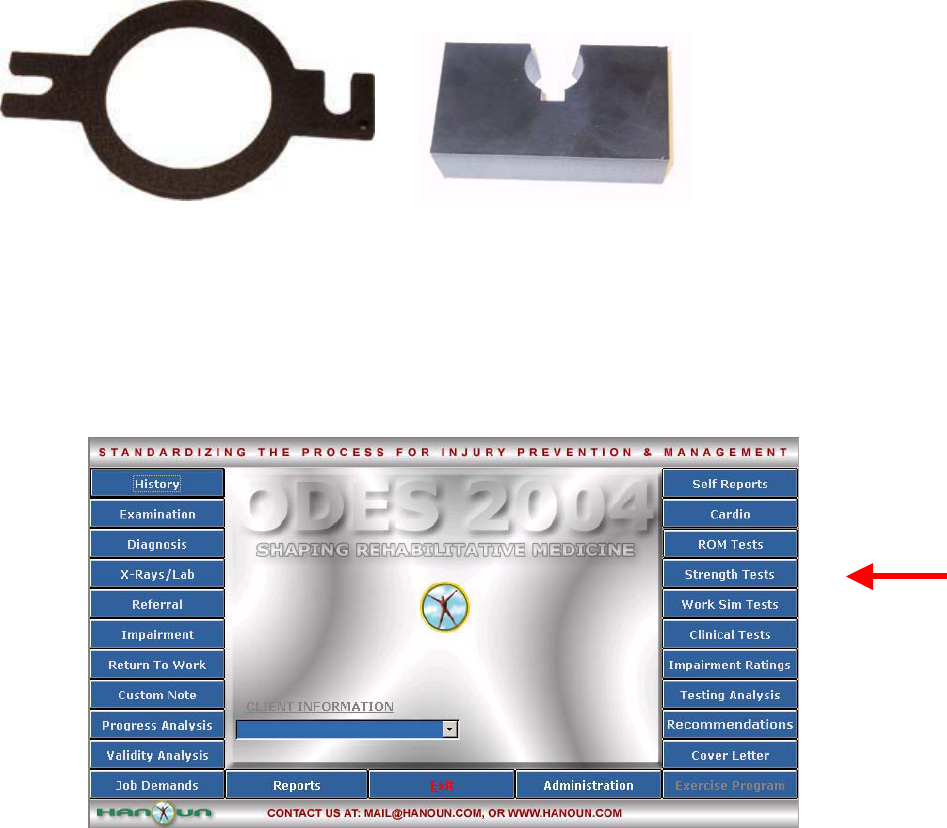
Accessories
The Hand Grip comes with the following pieces for calibration:
181
Using the Hand Grip For A Pre-Programmed Strength Protocol:
You are now ready to enter the Strength Test page.
Click on Strength Test from the ODES main menu. The following Strength Test Protocol page will
appear. From here, all of the pre-programmed tests may be accessed. Tests can be added to clients,
new custom isometric strength tests may be created, and tests can be edited or deleted.
182
Once a test has been added to a client, and Perform Test has been selected from the bottom right hand
corner of the page, the test page will appear. Below is an example of what the test page looks like for the
Standard Hand Grip.
Choose this
icon to Start
the Standard
Hand Grip
Test.
Choose this
icon to return to
the Strength
menu.
Located in this area are
the standardized
instructions for the
Hand Grip tests.
This is a list of all
the tests found in
the Strength Test
menu.
This is a short cut to return
to any of the test menu
screens in ODES¥. The
test menu that is in use will
appear in yellow.
Select this
icon to
return to
the
ODES™
main
menu.
All of the tests
that are
assigned to the
client will appear
in this area.
Double click on
the test or click
here to add it to
the tests assigned
to the client.
In order to edit, create or
remove tests, highlight
the work simulation
protocol then click on the
appropriate icon.
Protocol
Hibernation puts
unused protocols
in storage without
removing data.
Click on Start HR to start real time heart rate
monitoring. . There is also the option of
entering the heart rate manually by double
clicking on the question mark.
183
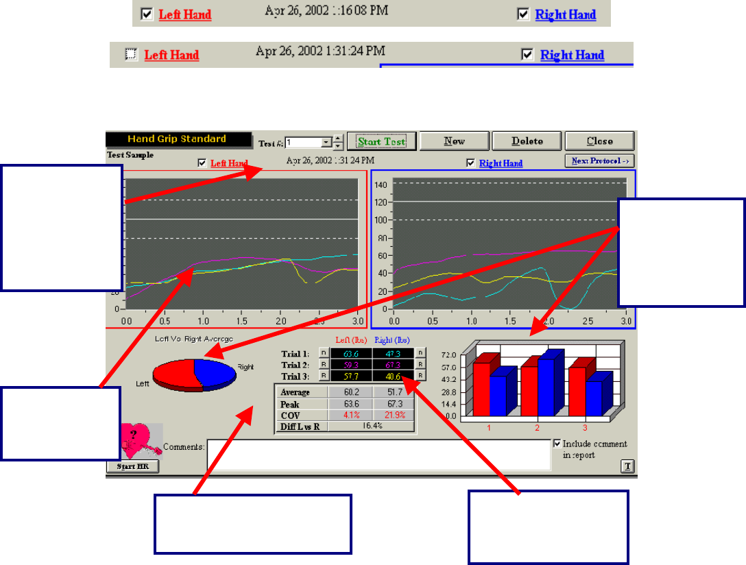
Notice that trials alternate between the client’s right and left hands. If only one hand requires testing,
simply remove the check mark beside the hand that is not required.
Below is an example of a completed Standard Hand Grip test.
The above is a completed Standard Hand Grip test. There are three trials on each side, each
represented by a different colour. The first trial is blue, the second is pink and the third trial is yellow.
Retesting Trials
Trials can be retested if the COV is off by more than 15%; if there is an error in technique; due to
inconsistent effort; or as a result of poor performance at the start or finish of the trials. There is no set
number of times that this option can be utilized.
The “R” represents a
retest option for each
trial that is performed
by the client.
The difference
between the left
and right hands
is represented
by both a pie
chart and a bar
Average, peak COV values
and difference between left
and ri
g
ht are dis
p
la
y
ed.
The test results
are displayed
in a line graph
f
o
rm
at
.
The trial, date
and time that
the test was
performed can
be found at the
top of the
testing screen.
184
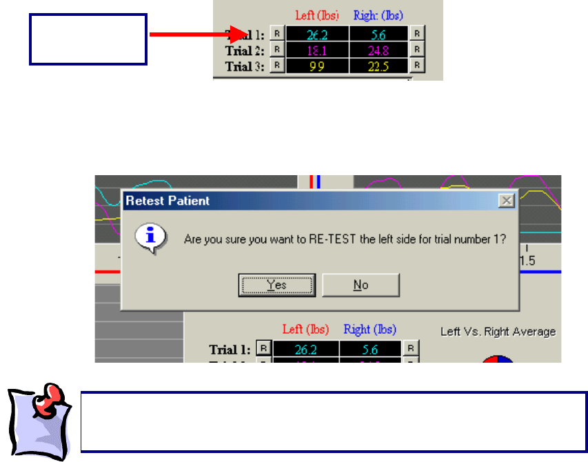
The “R” that corresponds with each trial is located to either the left or right of the initial result obtained.
For example, for trial one on the left side of the body, the “R” is located to the left of the result obtained by
the client. To redo this trial, click the R. ODES will then ask if this trial should be retested. Click OK and
perform the trial again.
Protocol Information
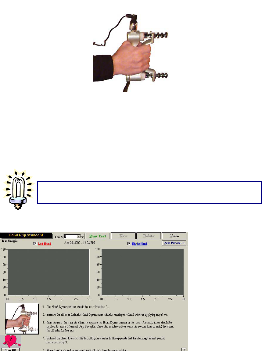
Standard Hand Grip:
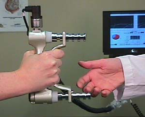
The “Hand Grip – Standard” test is performed per the BTE Hand Grip Protocol with a JAMAR handgrip
dynamometer. This device is utilized to measure handgrip strength in both the right and left hands.
Prepare the grip dynamometer by setting the adjustable handle spacing in position 2 (1-1/2 inches), or the
second position away from the fixed handle.
The device must be presented to the client with the cord attachment on top in order to conform to the
metacarpal arch of the hand.
Retest Option
“R” Button
It is important to note that once a testing screen is closed or a new trial is
created, the measurements that were obtained will be locked and none o
f
these can be retested.
185
The client should optimally be positioned sitting as follows:
Both feet flat on the floor
Upper arm next to body
Elbow flexed at 90 degrees
Forearm neutral (thumb up)
Hand & forearm in slight shoulder internal rotation (toward the center front of the torso)
Forearm should not be resting on any surface while gripping
Click Start Test at the top of the page.
The client is required to perform three trials with each hand with the dynamometer set to position 2,
beginning with the right hand and alternating between trials.
Voice prompts will guide the tester and the client through the trials. Observe the client closely to ensure
he/she understands.
If possible, have the client remove all rings from his/her fingers, as these can
interfere with the performance of this test.
186
Instruct the client to begin gripping the device in a smooth motion, steadily maintaining that grip until the
prompted “Rest Period,” then direct the client to switch the device to the contra lateral hand.
As with all interfaced test screens, data is automatically analyzed for the standard handgrip
strength test. A Comment section is available at the bottom of the screen. Double-click the text
box to increase its size if additional space is required. Click the box adjacent to “Include
Comment in Report” if these comments are to be included in the final printed report. A summary
of test results and comparison to normal values is provided in the report.
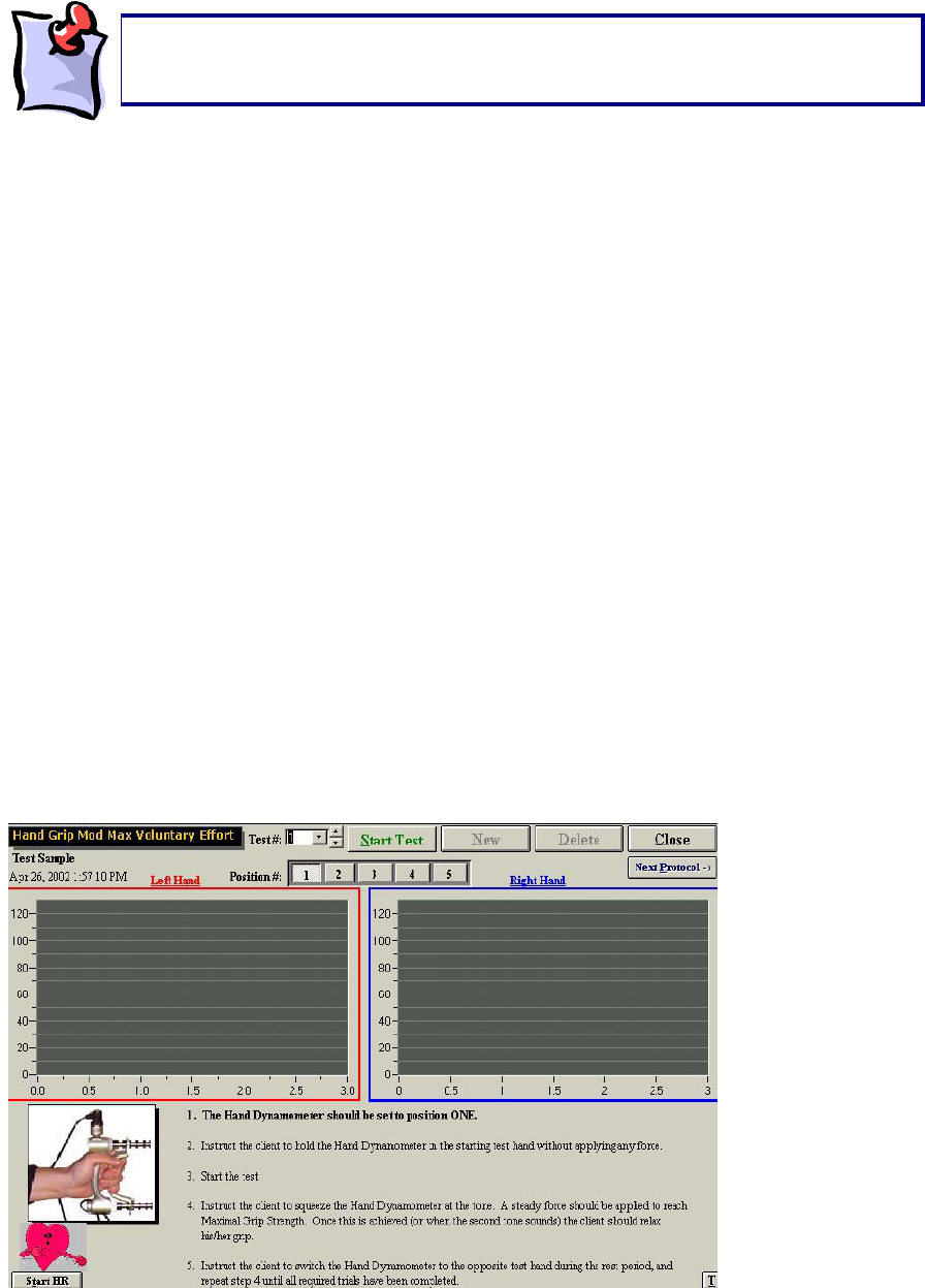
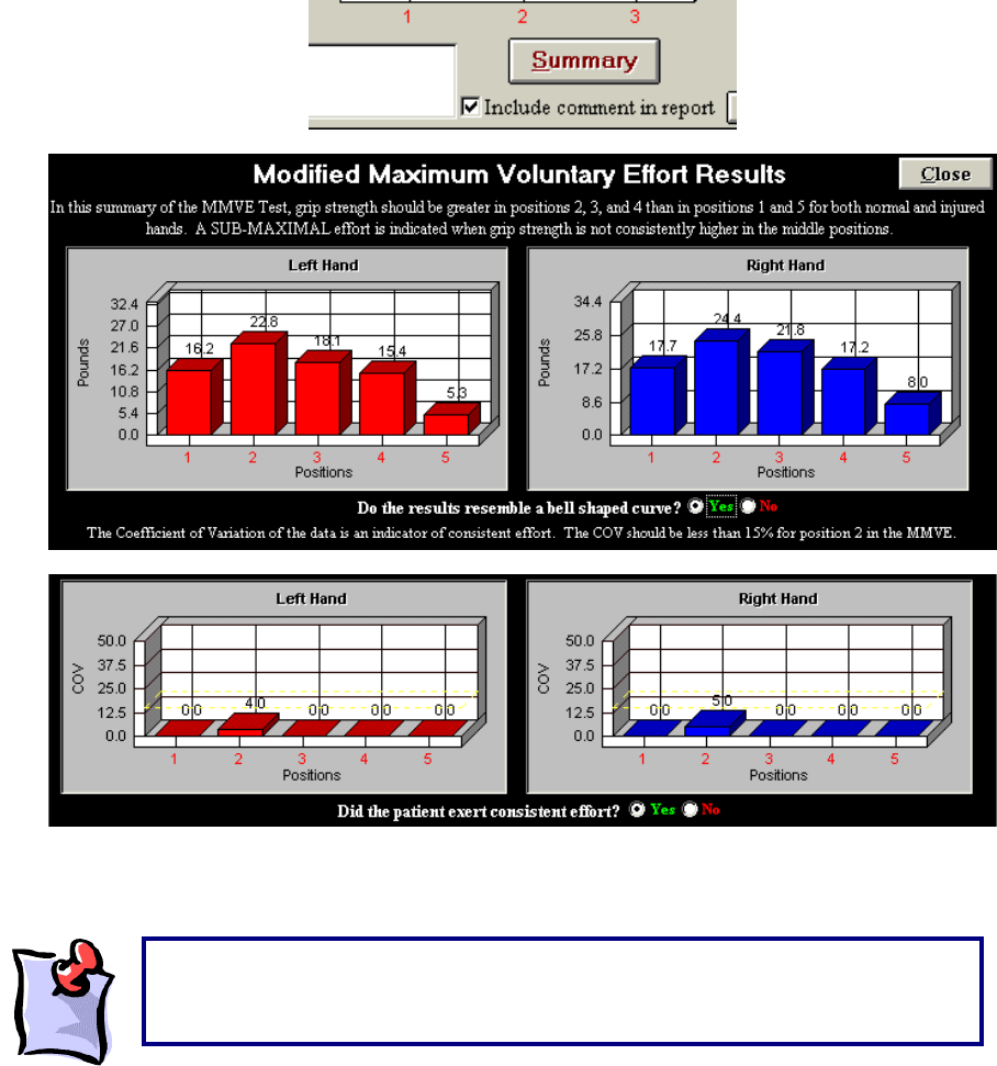
Modified Maximum Voluntary Effort:
The Handgrip Modified Maximum Voluntary Effort test page has two grids for real-time graphs of the left
and right hand strength curves. Each grid contains three reference lines that represent the normal values
as well as upper and lower limits for the client, based on his/her age and gender. These criteria are
obtained through the information the evaluator provides on the Client Information page of ODES. The
correct gender and date of birth of the client must be entered when performing these tests to ensure
accurate and complete data analysis. Hand dominance is also entered on the Client Information page.
This is also used in data analysis: right-dominant individuals are considered to be 10% stronger on the
right.
The MMVE test pages look much like the Handgrip Standard test page(s) with the following exceptions:
The main page has a row of buttons from 1 to 5 to indicate the spacing position on the handgrip
dynamometer.
The page displayed at the conclusion of testing at each handgrip position has a Summary button.
It is important that the client does not grip the dynamometer firmly prior to beginning
the test to ensure proper calculation of the starting threshold. The voice prompt will
announce “Start Test Now” to indicate when firm
p
ressure should be a
pp
lied.

187
Click button number 1 (from 1 – 5) at the top of the screen. These buttons represent the choice of
spacing positions on the grip dynamometer.
The test is performed with one trial of each hand at spacing positions 1, 3, 4 and 5 on the dynamometer,
and three trials of each hand for spacing position 2.
The Modified Maximum Voluntary Effort Handgrip test is performed per the BTE Handgrip Protocol with a
JAMAR handgrip dynamometer. This device is utilized to measure handgrip strength in both the right and
left hands.
Prepare the grip dynamometer by setting the adjustable handle spacing for the position to be tested:
Position One: 1 inch
Position Two: 1-1/2 inches
Position Three: 2 inches
Position Four: 2-1/2 inches
Position Five: 3 inches
The test is generally conducted with position one first, and progresses chronologically until position five is
completed.
The device must be presented to the client with the cord attachment on top in order to conform to the
metacarpal arch of the hand.
The client should optimally be positioned sitting as follows:
Both feet flat on the floor
Upper arm next to body
Elbow flexed at 90 degrees
Forearm neutral (thumb up)
Hand & forearm in slight shoulder internal rotation (toward the center front of the torso)
Forearm should not be resting on any surface while gripping
Text instructions are given on the test page. Voice prompts will guide the tester and the client through the
test. Observe the client closely to ensure he/she understands.
Instruct the client to begin gripping the device in a smooth motion, steadily maintaining that grip until the
prompted “Rest Period,” then direct the client to switch the device to the contra lateral hand.
Repeat these steps for all five-grip positions.
The MMVE test is performed over a range of positions effecting varying degrees of difficulty. Therefore, it
is possible to determine whether a client has performed with consistent effort by comparing the objective
strength values recorded at each position for each hand. Shown graphically, the plots of these values
would be expected to create a bell-shaped pattern, paralleling that of the contra lateral hand. A
significant-appearing deviation in the size of the curve or the absence of a bell-shaped curve would
connote non-compliance of the client with the strength test.
ODES immediately plots the data. Graphic representations for both right and left-hand results are found
by clicking the Summary button located at the bottom right corner of the page.
It is important that the client does not grip the dynamometer firmly prior to beginning
the test to ensure proper calculation of the starting threshold. The voice prompt will
announce “Start Test Now” to indicate when firm
p
ressure should be a
pp
lied.
188
Click Yes if both graphs follow a bell-shaped distribution.
Click No if one or both graph(s) does/do not correspond to the bell-shaped curve.
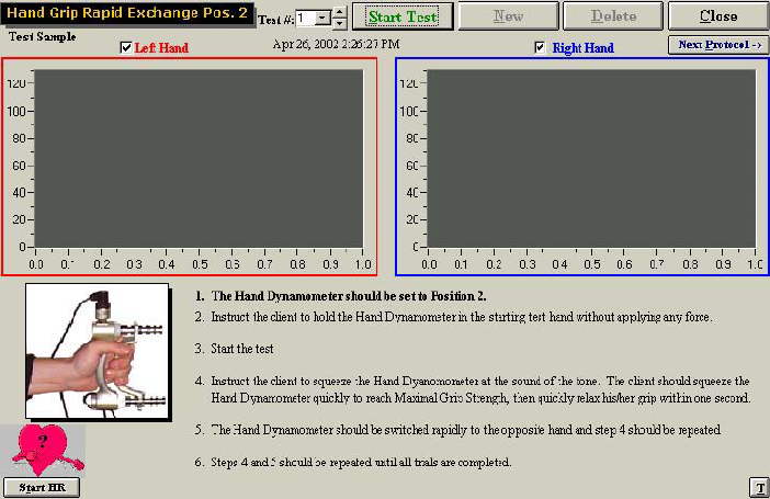
Rapid Exchange:
The “Rapid Exchange Grip” test page has two grids for real-time graphs of the left and right-hand strength
curves.
If the evaluator does not click on Summary, the cross validation section of the
report (assuming the Rapid Exchange Grip and the Standard Hand Grip tests
were completed) will not be included.
189
The “Hand Grip – Rapid Exchange” test is performed with a JAMAR handgrip dynamometer. This device
is utilized to measure handgrip strength in both the right and left hands.
The “Hand Grip – Rapid Exchange” test is performed by having the client rapidly squeeze the grip
dynamometer and move it to the other hand for a series of six trials each for both right and left hands.
The adjustable handle component of the grip dynamometer is to be set up in spacing position two. The
average maximum force for all six trials is compared to the values obtained for the standard or MMVE
handgrip strength test for validity purposes.
Prepare the grip dynamometer position as indicated on the screen. If the client has completed the
Modified Maximum Validity Effort test, the adjustable handle spacing will be in position 2 (1-1/2 inches), or
the second position away from the fixed handle. If the Maximum Validity Effort test was completed the
position will be based on the position where the client registered the strongest readings. The device must
be presented to the client with the cord attachment on top in order to conform to the metacarpal arch of
the hand.
The client should optimally be positioned sitting as follows:
Both feet flat on the floor
Upper arm next to body
Elbow flexed at 90 degrees
Forearm neutral (thumb up)
Hand & forearm in slight shoulder internal rotation (toward the center front of the torso)
Forearm should not be resting on any surface while gripping
Click Start Test at the top of the page.
Voice prompts will guide the tester and the client through the test. Observe the client closely to ensure
he/she understands.
Instruct the client to begin gripping the device quickly and with maximum force for a one-second trial
duration beginning with the right hand. The client must follow the voice prompts to “Switch to Left,” and
“Switch to Right” to complete 6 consecutive trials each of both right and left hands.
190
The BTE Protocol for Rapid Exchange Handgrip Strength testing will automatically prompt ODES to
perform a cross-reference validity check to compare the results of the Rapid Exchange or MMVE to the
Standard handgrip results. ODES will automatically calculate and compare the values obtained from
strength test performance using the grip dynamometer in position two for all tests. The client’s strength
values recorded during the Standard or MMVE tests are not expected to show a variance of greater than
15% from those recorded during Rapid Exchange handgrip strength testing.
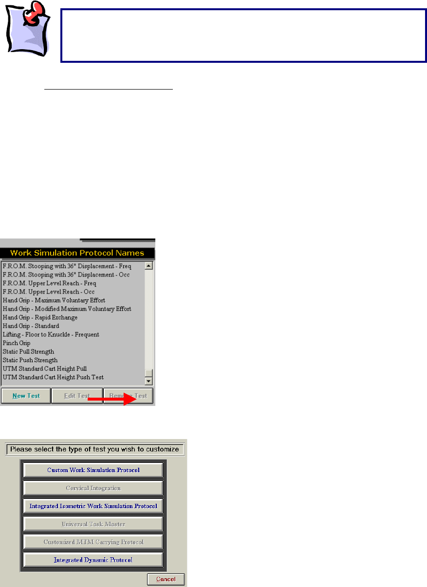
Creating A New Hand Grip Test:
The ODES software allows for the creation of new protocols. In order to do so, enter the page from which
tests can be chosen. In this case, enter the Strength Test or Work Sim Test page. At the bottom of the
page is a button labelled New Test.
After selecting this option, the following page will appear:
Select the Integrated Isometric Work Simulation Protocol or Integrated Strength Test Protocol option in
this menu in order to begin customizing the new Hand Grip test.
It is important that the client does not grip the dynamometer firmly prior to
beginning the test to ensure proper calculation of the starting threshold. The
voice prompt will announce “Start Test Now” to indicate when firm pressure
should be a
pp
lied.
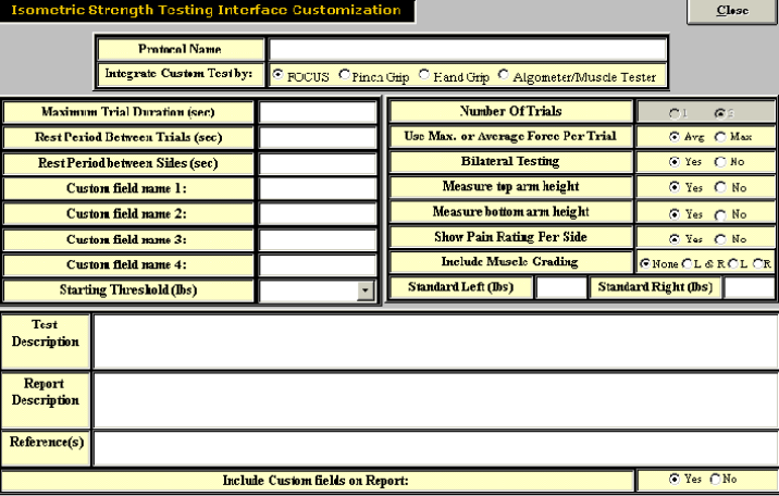
191
A page will then appear which will allow input of all the essential protocol information.
Once all of the vital information has been entered, click Close. The test should now appear in the
protocol listing.
192
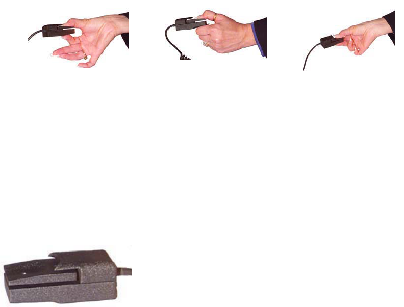
The Pinch Grip
Force Measurement
The main force measurement device can accurately document values from 0—70 lbs. The device itself is
accurate to 0.037% over a full scale and, when combined with the software and other components, is
accurate to 0.2% over the full scale (i.e. within one pound at all times).
Cables
BTE uses high grade cabling to ensure the durability of its connections.
Protocols
The standardized Pinch Grip tests in the ODES software can be used to determine a client’s Pinch Grip
strength relative to a population of the client’s age and sex, using normative data. There are various
protocols for performing Pinch Grip testing and these are listed below.
Design
This tool is made of aluminum and documents values via a load cell device.
Tip Pinch Key Pinch Palmar Pinch
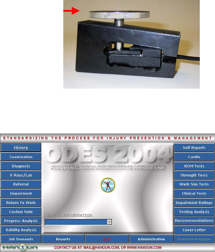
193
Accessories
The Pinch Grip comes with the following pieces for calibration. Weight of the calibration disc = 0.3 lbs.
Using the Pinch Grip For A Pre-Programmed Strength Test Protocol:
The following is an example of how to perform a pre-programmed Strength Test Protocol.
From the ODES main menu, click Strength Test. This will bring you to the Strength Protocols page.
From here, you have access to all of the pre-programmed tests. You can add tests to clients, create new
custom isometric strength tests, edit tests and delete tests.
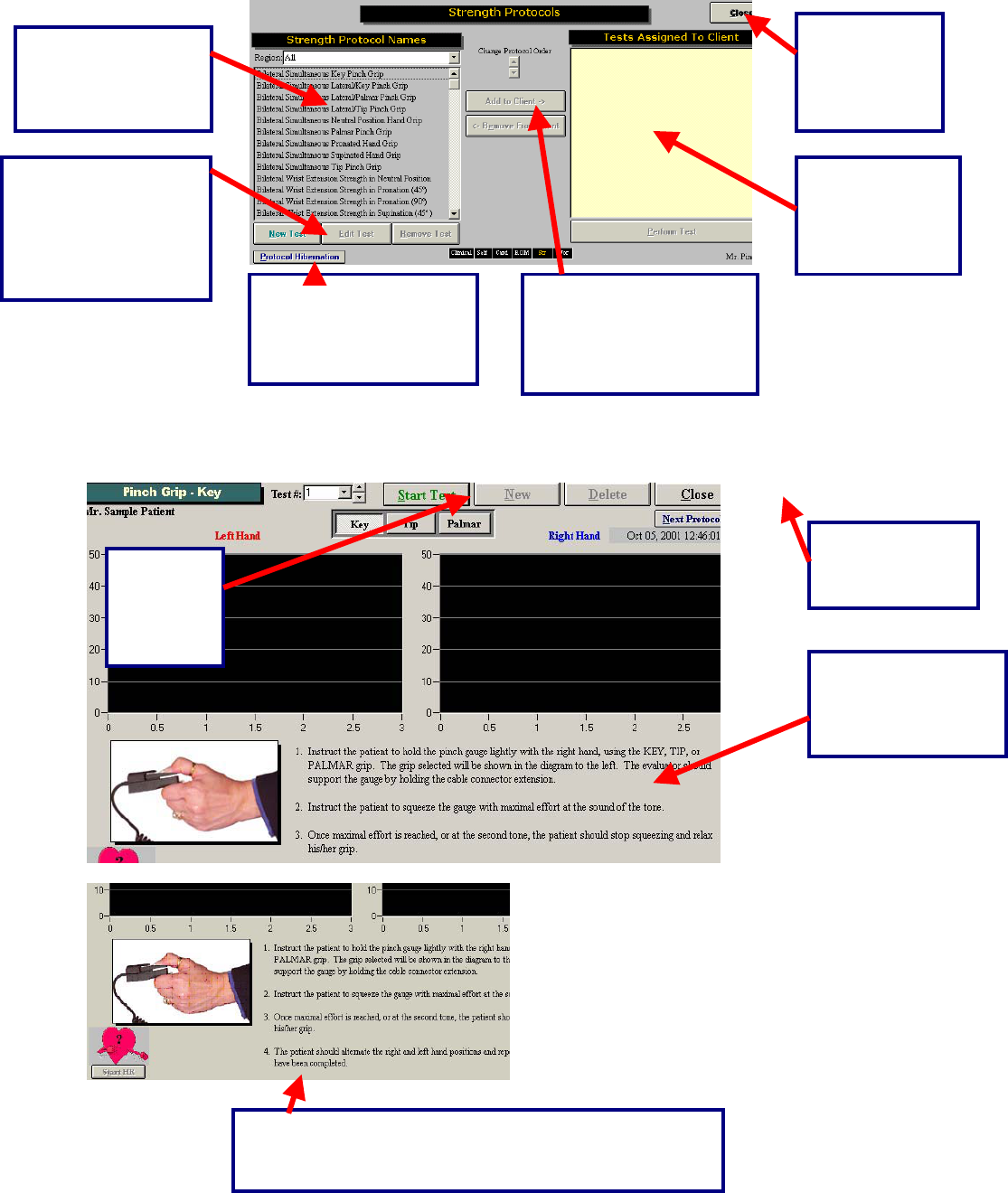
194
Once a test has been added to a client, and Perform Test has been clicked in the bottom right hand
corner of the page (or the test itself has been double-clicked), the test page will appear. Below is an
example of what the test page looks like for the standardized Pinch Grip.
This is a list of all
the protocols found
in the Work
Simulation menu.
This is a short cut to return to any of the test
menu screens in ODES¥. The test menu
that is in use will appear yellow.
Select this
button to
return to the
ODES™ main
menu.
All of the tests
that are
assigned to the
client will appear
in this area.
Double click on the test
or highlight the test and
click here to assign it to
the client.
In order to edit, create
or remove tests,
highlight the work
simulation protocol
then click on the
appropriate button.
Located in this area
are the standardized
instructions for the
Pinch Grip tests.
Click this
button to
start the
Key Pinch
Test.
Click Start HR to capture the client’s heart rate during the
test. You also have the option of entering the heart rate
manually by double-clicking on the heart graphic
Click this button
to return to the
Strength menu.
Protocol Hibernation
puts unused protocols in
storage without
removing data.

195
Below is an example of a completed Key Pinch Grip test.
Three trials are performed on each hand, represented by a different color. Trial number one is blue, trial
number two is pink and trial number three is yellow.
Capturing Client’s Heart Rate:
Retesting Trials
Trials can be retested if the COV is off by more than 15%. In addition, if there is an error in technique,
inconsistent effort, or poor performance at the start or finish of a test the trials may also be re-tested.
There is no set number of times that this option can be utilized.
The difference
between the left
and right side is
represented by
both a pie chart
and a bar graph.
The test results
are displayed in
a line graph
format.
The trial, date and
time that the test
was performed can
be found at the top
of the testing page.
Average, peak
COV values and
difference
between left and
right are
displayed.
The “R” represents a
retest option for that
specific trial.
This can be done by
either clicking the start
HR button, or by double-
clicking on the heart
graphic and entering the
value manually.
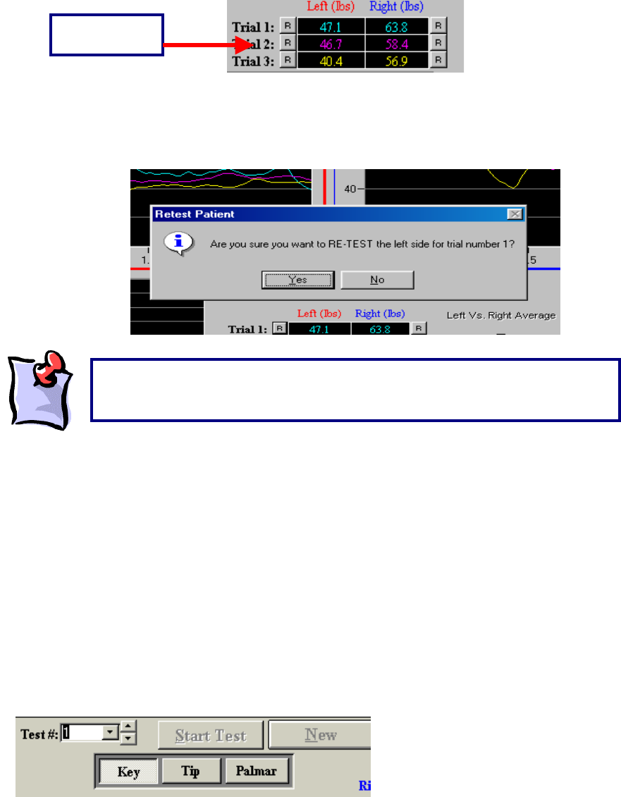
196
The “R” that corresponds with each trial is located to either the left or right of the initial result obtained.
For example, for trial one on the left side of the body, the “R” is located to the left of the result obtained by
the client. To redo this trial, click on “R”. ODES will then ask if you would like to redo this trial. Click OK
and perform the trial again.
Protocol Information
Key Pinch:
The Key Pinch strength test is performed as per the protocol outlined in published research (refer to
abstracts on ODES CD). This pinch dynamometer measures strength in the key (lateral) pinch position of
both the right and left hands.
To access the test from the ODES main menu, go to Strength Test and select Pinch Grip from the list on
the left-hand side of the page. Within this testing page, you will find a row of buttons located at the top
labelled ‘Key,’ ‘Tip,’ and ‘Palmar.’ These buttons correspond to the three types of Pinch Grip tests.
Click Key to perform a Key Pinch Grip Test.
Retest Option
“
R
”
Button
It is important to note that once you either close the testing page or create a ne
w
trial, the measurements that were obtained will be locked and you will be unable
to retest an
y
of the trials.
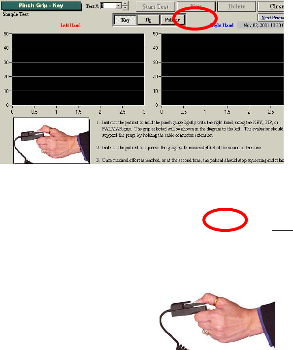
197
The “Pinch Grip – Key” screen has two grids for real-time graphs of the left and right hand strength
curves. Each grid contains three reference lines that represent the normal values as well as upper and
lower limits for the client, based on their age and gender, and hand dominance. This information is
obtained through the information the evaluator provides in the Client Information screen of ODES. The
correct gender, date of birth and hand dominance of the client must be entered when performing these
tests to ensure accurate and complete data analysis.
Instruct the client to hold the Pinch Grip dynamometer between the thumb and the lateral aspect of the
index finger, middle phalanx similar to how they would hold a key.
3. The client is in a seated position as follows:
Both feet flat on the floor
Upper arm next to body
Elbow flexed at 90 degrees
Hand & forearm in slight shoulder internal rotation (toward the centre front of the torso)
Forearm should not be resting on any surface while pinching
Click Start Test to start the Pinch Grip Test.
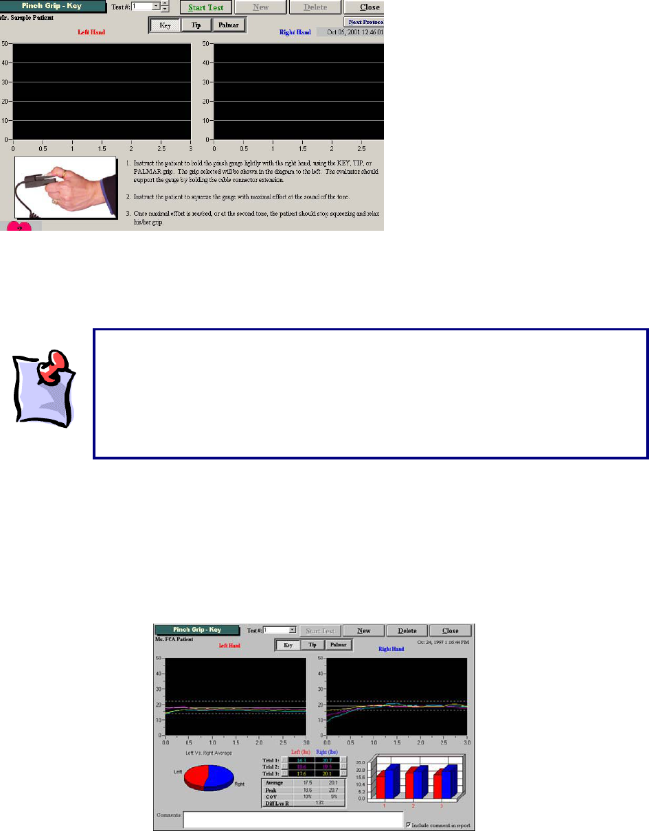
198
The client is required to perform three trials with each hand, beginning with the right hand and alternating
with the contra lateral hand between trials. Voice prompts will guide the evaluator and the client through
the test. Observe the client closely to ensure they understand and have assumed correct Key Pinch-type
positioning.
As with all interfaced test pages, data is automatically analyzed for the Key Pinch strength test. The
average of the three trials is compared to published population normative values. A ‘Comment’ section is
available at the bottom of the page. You may double-click the text box to increase its size as indicated by
the length of your commentary. You have the choice to include or not include your comments in the
report by selecting the ‘Include comment in report’ checkbox A summary of test results and comparison to
normative values is provided in the report.
When beginning the Key Pinch test, have the client grip the pinch gauge loosely. It is
important that the client does not grip the pinch gauge firmly prior to beginning the test
to ensure proper calculation of the starting threshold. The voice prompt will announce
“Start test now,” at which time the client may begin pinching the device in a smooth
motion, steadily maintaining the Key Pinch grip for a three-second trial duration until
prompted “Rest period,” and directed to switch the device to the contra lateral hand.
This process is repeated three times.
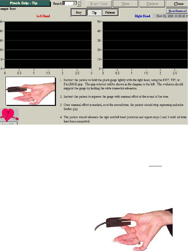
199
Tip Pinch:
The Tip Pinch strength test is performed per the protocol outlined in published research (see ODES CD
for abstracts) with a Pinch Dynamometer. This Pinch Grip dynamometer measures strength in the tip (tip-
to-tip) pinch position of both the right and left hands.
Click Tip to perform a Tip Pinch Grip Test.
The Tip Pinch Grip screen has two grids for real-time graphs of the left and right hand strength curves.
Each grid contains three reference lines that represent the normal values as well as upper and lower
limits for the client, based on their age, gender and hand dominance. This information is obtained
through the information the evaluator provides in the Client Information screen of ODES. The correct
gender, date of birth and hand dominance of the client must be entered when performing these tests to
ensure accurate and complete data analysis.
Instruct the client to hold the Pinch Grip device between the thumb tip and the tip of the index finger as
shown below.
The client should optimally be in a seated position as follows:
Both feet flat on the floor
Upper arm next to body
Elbow flexed at 90 degrees
Hand & forearm in slight shoulder internal rotation (toward the centre front of the torso)
Forearm should not be resting on any surface while pinching
Click Start Test to start the Tip Pinch Grip Test.
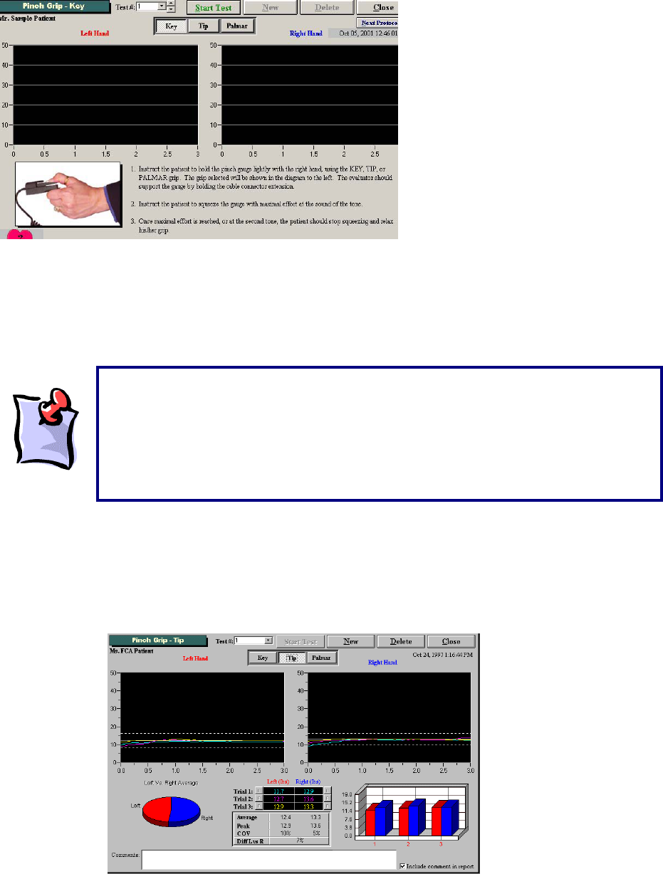
200
The client is required to perform three trials with each hand, beginning with the right hand and alternating
with the contra lateral hand between trials.
Voice prompts will guide the evaluator and the client through the test. Observe the client closely to
ensure they understand and have assumed correct Tip Pinch-type positioning.
As with all interfaced test pages, data is automatically analyzed for the Tip Pinch strength test. The
average of the three trials is compared to published population normative values. A “Comment” section is
available at the bottom of the page. You may double-click the text box to increase its size as indicated by
the length of your commentary. You have the choice to include or not include your comments in the
report by selecting the “Include comment in report” checkbox. A summary of test results and comparison
to normative values is provided in the report.
When beginning the Tip Pinch test, have the client grip the pinch gauge loosely. It is
important that the client does not grip the pinch gauge firmly prior to beginning the
test to ensure proper calculation of the starting threshold. The voice prompt will
announce “Start test now,” at which time the client may begin pinching the device in a
smooth motion, steadily maintaining the Tip Pinch grip for a three-second trial
duration until prompted “Rest period,” and directed to switch the device to the contra
lateral hand. This process is repeated three times.
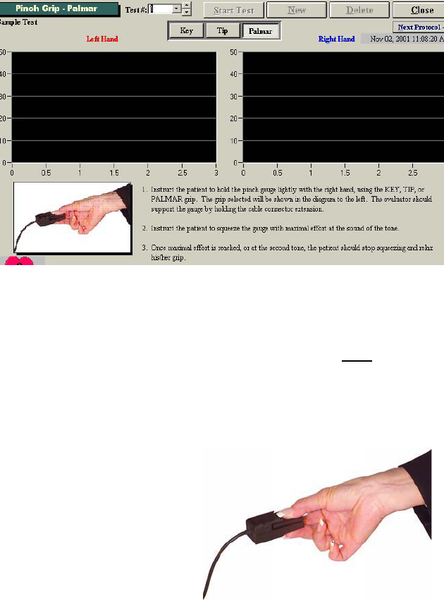
201
Palmar Pinch:
The Palmar Pinch Grip strength test is performed per the protocol outlined in published research (see
ODES CD for Pinch Strength Protocol) with a Pinch Dynamometer. This Pinch Grip dynamometer
measures strength in the Palmar Pinch position of both the right and left hands.
Click Palmar to perform a Palmar Pinch Grip Test.
The “Pinch Grip – Palmar” screen has two grids for real-time graphs of the left and right hand strength
curves. Each grid contains three reference lines that represent the normal values as well as upper and
lower limits for the client, based on their age, gender and hand dominance. This information is obtained
through the information the evaluator provides in the Client Information screen of ODES. The correct
gender, date of birth and hand dominance of the client must be entered when performing these tests to
ensure accurate and complete data analysis.
Instruct the client to hold the pinch dynamometer between the tip of the thumb and the tips of the index
and middle fingers.
The client should be in a seated position as follows:
Both feet flat on the floor
Upper arm next to body
Elbow flexed at 90 degrees
Hand & forearm in slight shoulder internal rotation (toward the centre front of the torso)
Forearm should not be resting on any surface while pinching
Click Start Test to start the Palmar Pinch Grip Test.
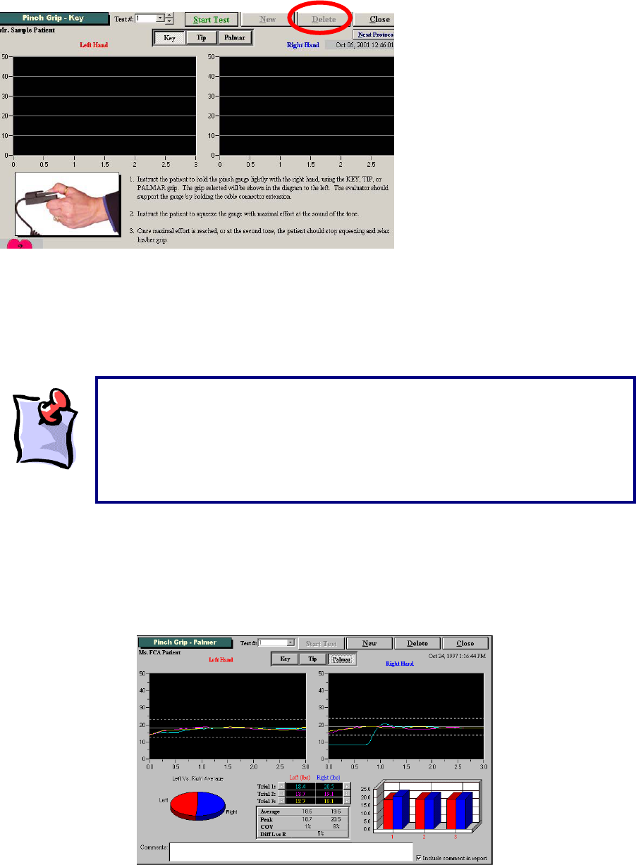
202
The client is required to perform three trials with each hand, beginning with the right hand and alternating
with the contra lateral hand between trials.
Voice prompts will guide the evaluator and the client through the test. Observe the client closely to
ensure they understand and have assumed correct Palmar Pinch-type positioning.
As with all interfaced test pages, data is automatically analyzed for the Palmar Pinch strength test. The
average of the three trials is compared to published population normative values. A “Comment” section is
available at the bottom of the page. You may double-click the text box to increase its size as indicated by
the length of your commentary. You have the choice to include or not include your comments in the
report by selecting the “Include comment in report” checkbox. A summary of test results and comparison
to normative values is provided in the report.
When beginning the Palmar Pinch test have the client grip the pinch gauge
loosely. It is important that the client does not grip the pinch gauge firmly prior to
beginning the test to ensure proper calculation of the starting threshold. The voice
prompt will announce “Start test now,” at which time the client may begin pinching
the device in a smooth motion, steadily maintaining the Tip Pinch grip for a three-
second trial duration until prompted “Rest Period,” and directed to switch the
device to the contra lateral hand. This
p
rocess is re
p
eated three times.
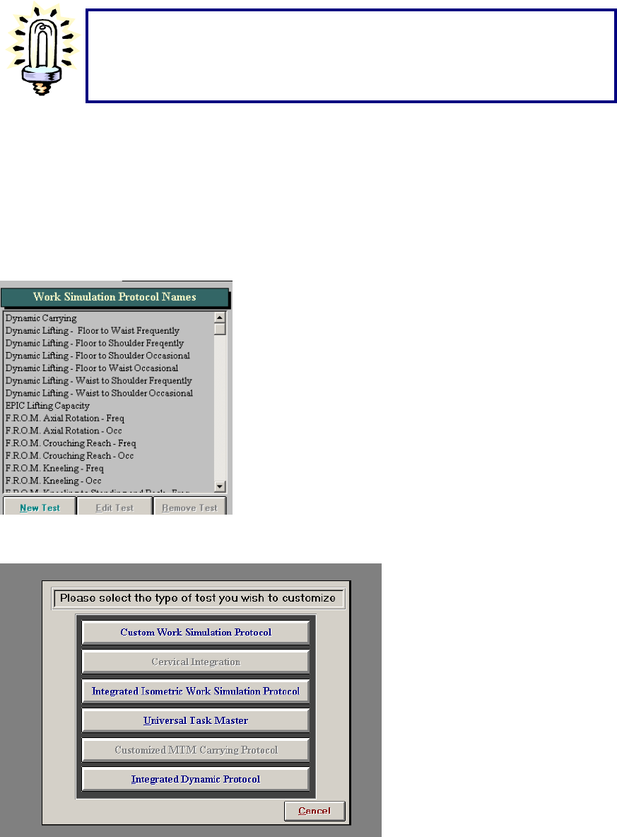
203
Creating A Custom Pinch Grip Test:
The ODES software allows for the creation of custom protocols. To do so, from the ODES main menu go
to either the Strength Tests or Work Simulation Tests pages from which tests can be chosen. In this
case, we have entered the Work Simulation page. Along the bottom is a button labelled New Test. Click
New Test to begin creating a new protocol.
After selecting this option, the following page will appear:
Click on Integrated Isometric Work Simulation Protocol or Integrated Isometric Strength Protocol,
depending on from which page you are creating the new test. A page will be displayed which allows you
to input all of the essential protocol information.
Make sure that you press the next Pinch Grip test (i.e.
key, Tip or palmar) before hitting the “Start” button.
If not, you will repeat the sa
me test that was just
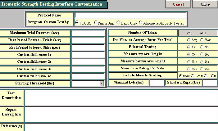
204
Select the tool you wish to use for this particular test and add in the protocol name. The maximum trial
duration, rest period between trials, and rest period between sides will be based on the type of test you
are trying to create. If you are trying to develop a strength test, consideration needs to be made regarding
the fatigability of the muscle(s) you are trying to test and the rest period created must be sufficient to
regain energy supplies. Generally a 3 second trial duration, with a 5 second rest period between trials and
a 5 second rest period between sides are acceptable parameters for testing muscle strength. If
developing the test to simulate a specific activity, set the parameters based on the task you are trying to
simulate. The closer the test is to the task the more valid the results will be.
Once all of the vital information is completed on this screen click Close. Your test should now appear in
your protocol listing under the protocol name.
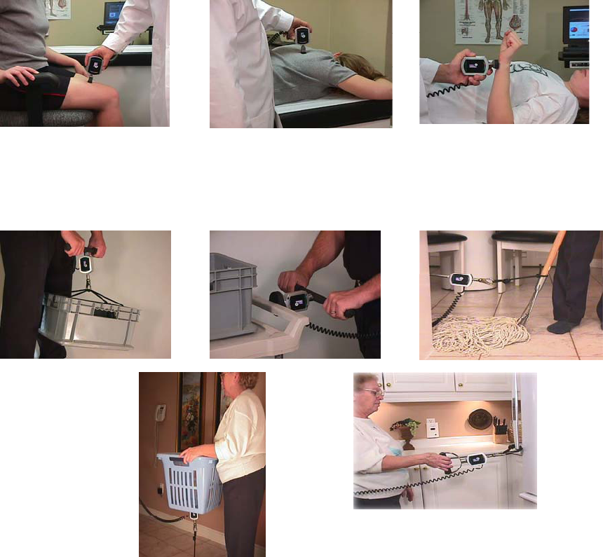
205
The BTE Algometer
Force Measurement
The main force measurement device can accurately document values from 0—500 lbs. The device itself
is accurate to 0.037% over the full scale and when combined with the software and other components are
accurate to 0.2% over the full scale (i.e. within one pound at all times).
Cables
BTE uses high grade cabling to ensure the durability of its connections.
Protocols
The pressure Algometer can be used for manual muscle testing or for evaluating the consistency of a
client’s self-report of pain. The pressure Algometer is an excellent tool in documenting point-tenderness,
especially in chronic pain clients. The pressure Algometer can also be used to develop customized work
simulation protocols.
Job Site Analysis—The pressure Algometer can be used to document the weights and forces required at
the workplace. This is ideal when you need to determine these measures prior to performing a functional
evaluation.
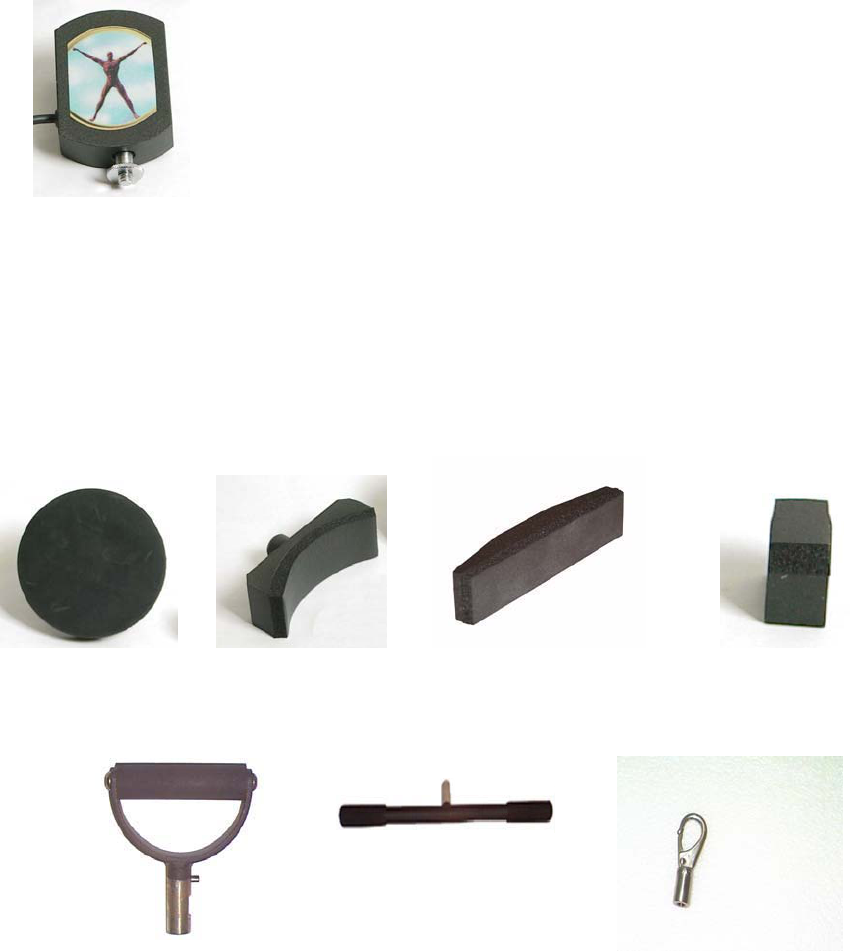
206
Design
This tool is made of aluminum and documents values via a load cell device. There is a fixed bolt in one
end, and a bolt can be added at the other end so that attachments can be fixed to both ends of the tool.
Accessories
The pressure Algometer comes with a round pad, a large concave manual muscle testing pad, a small
rectangular muscle testing pad, a 1 cm squared point tenderness testing pad, a single handle, a straight
bar, a clip, small and large corner accessories, an extension piece, a nylon strap, and a bolt. Depending
on the year and the type of system purchased, the accessories below may vary.
Round Pad: Concave Pad: Rectangular Pad: Tenderness
Testing Pad:
Single Handle: Push/Pull Bar: Clip:
Small Corner Accessory: Large Corner Accessory: Calibration Tool
(Pinch Grip or
Algometer):
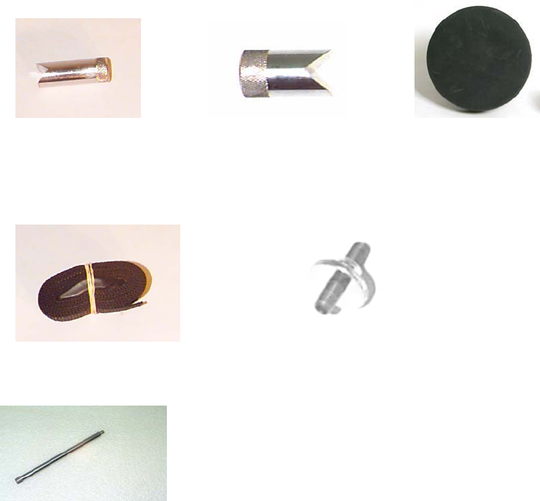
207
wt = 0.4 lbs
Strap Attachment: Bolt:
Extension Piece for Hard to Reach Areas:
Factors To Take Into Consideration:
There are several factors that need to be taken into account when developing an isometric strength test.
The evaluator should ensure that the test isolates the targeted muscle group and that it reduces the
amount of accessory muscle use.
Types of Strength Protocols
The ODES™ 2002 software has many Strength protocols pre-programmed into the software. These tests
include:
Spinal strength tests such as Cervical Neutral Flexion, Extension and Side Flexion
Upper Extremity strength tests such as Wrist Flexion and Extension, Elbow Flexion and Extension,
Shoulder Flexion, Extension, Abduction, Adduction, Internal Rotation and External Rotation
Lower Extremity strength tests such as Ankle Plantarflexion and Dorsiflexion, Knee Flexion and
Extension, Hip Flexion, Extension and Abduction
The software also permits the user to customize a Strength test.
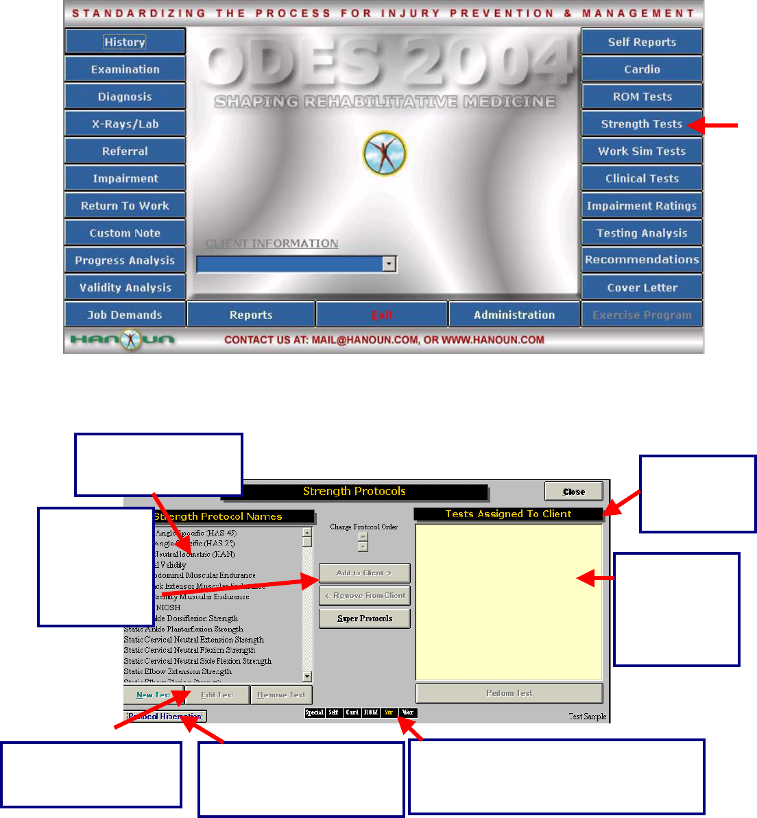
208
Using the Pressure Algometer for A Pre-Programmed Isometric Strength Protocol:
Click Strength Test from the main menu of ODES. This will bring you to the Strength Test page. From
here, you have access to all of the pre-programmed strength tests. You can add tests to clients, create
new custom isometric strength tests, edit tests and delete tests.
This is a list of all the
tests found in the
Strength Test menu.
These are short cuts to return to any of the
test menu pages in ODES¥. The test menu
that is in use will appear in yellow.
click this
button to
return to the
ODES™ main
All of the tests
assigned to the
client will appear
in this area.
Highlight the
test and click
here or double
click on the
test name to
assign it to a
client
In order to edit, create or
remove tests, click on the
appropriate button.
Protocol Hibernation puts
unused protocols in storage
without removing data
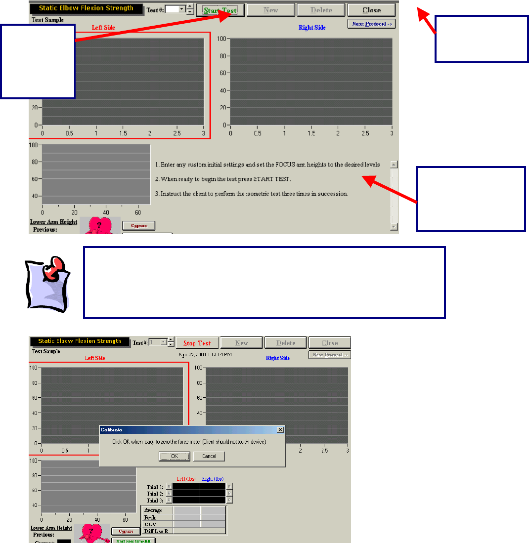
209
Once a test has been assigned to a client, and Perform Test has been selected at the bottom right-hand
corner of the page (alternately, you may double click on the test name), your test page will appear.
Located in this area
are the default or
custom instructions
for the
corres
p
ondin
g
test.
Click this
button to
Start the
Strength
test.
Click this button
to return to the
Strength menu.
It should be noted that once the Start button is selected, a message will
appear stating that the force meter needs to be zeroed. This is seen in the
picture below. As there are many attachments for each load cell, ODES¥ will
account for the weight of the accessory attachment during each test. No force
should be applied to the force meter.
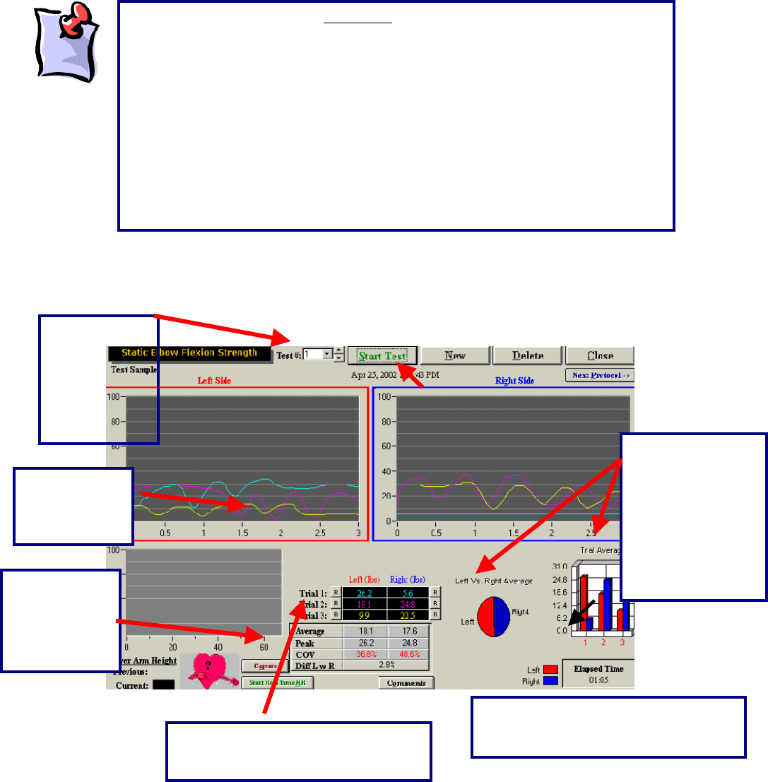
210
Once the Algometer has been zeroed (i.e. no force applied to it), you are ready to begin the strength test.
With the static strength tests, all trials are performed on the left side initially and then repeated on the
right side.
The above is
a
The difference
between the left
and right side is
represented by
both a pie chart
and a bar graph.
In addition, the
total elapsed time
is displayed.
The test
results are
displayed in a
line
g
ra
p
h
The trial, date
and time that
the test was
performed can
be found at the
top of the
testing page.
A
vg., peak and
COV values
are listed for
right and left
comparison.
The “R” represents a retest option for
each trial that is performed by the
client.
The comments button allows the
evaluator to enter their observations
from the test.
It is important to note that only one device can be linked with a static test. For
example, if you have done a static shoulder abduction strength test with the FOCUS
unit, you will always have to use this device for this test. This ensures that the data
being recorded remains objective. If you have a larger system (a FOCUS platform
and an Algometer) you should create duplicate copies of the tests. This will allow
you to utilize both pieces of equipment – the FOCUS and Algometer (since both
devices can measure static strength). For example, you could name the existing
cervical strength test in the database “Cervical Strength – FOCUS” and create
another identical test and name it “Cervical Strength – Algometer.” Each test would
utilize a different tool. In order to understand this further, please see the
troubleshooting section at the end of this manual. If you have a smaller system (such
as the Evaluator or CIRES) you will only have an Algometer and will not have to
create different tests.
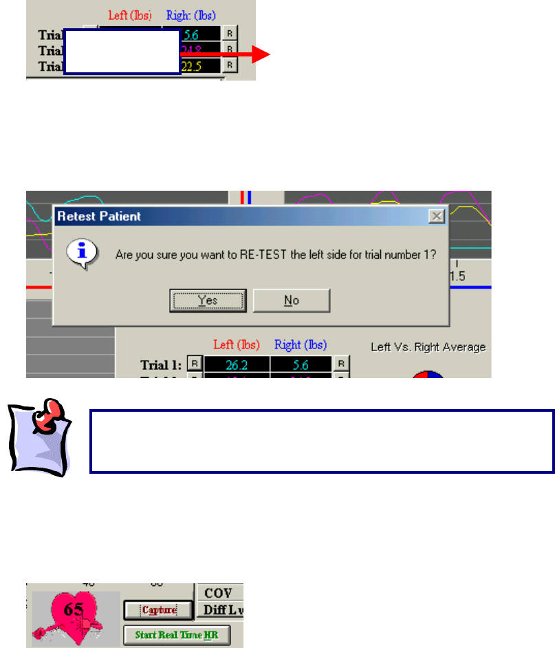
211
completed static shoulder abduction strength test. There are three trials on each side, each represented
by a different colour. Trial number one is blue, trial number two is pink and trial number three is yellow.
Retesting Trials
If there is an error in technique, inconsistent effort, or poor performance at the start or finish of a test the
trials can be re-tested. There is no set number of times that this option can be utilized.
The ‘R’ that corresponds with each trial is located at either the left or right of the initial result obtained.
For example, for trial one on the left side of the body, the ‘R’ is located to the left of the result obtained by
the client. To redo this trial, click the R.
ODES will then ask you if you would like to redo this trial. Click Yes and perform the trial again.
Checking the Heart Rate:
Recording the Heart Rate can be performed by either clicking the Capture button, or by double clicking on
the heart graphic and entering the value manually (once you have entered the heart rate in the white box
hit the enter key).
Click Start Real Time HR to start the real time heart rate function.
Retest Option
‘R’ Button
It is important to note that once you either close the testing page or
create a new trial, the measurements that were obtained will be locked
and you will be unable to retest any of the trials.
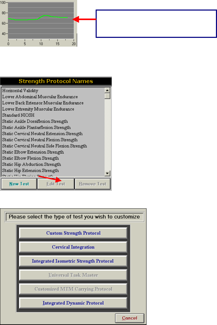
212
Creating A New Isometric Strength Protocol
The ODES software allows you to create new protocols. To do so, open Strength Test _ New Test from
the ODES main page.
After clicking New Test, the following page will appear:
Real Time Heart Rate allows you to track the HR
in a graph format. This is only for those who
have the TEST, evalTECH, or ER Systems..
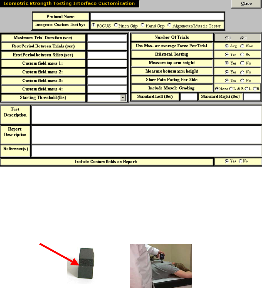
213
From this page, select the Integrated Isometric Strength Protocol option in order to begin customizing
your new strength test. The customization page will be displayed, which will allow you to input all of the
essential protocol information.
Once all of the vital information is completed on this page, click Close. Your test should now appear in
your protocol listing.
Superficial Tenderness
With disorders, such as fibromyalgia, becoming more common in a clinical setting, two different superficial
tenderness templates have been added into the ODES software.
For superficial tenderness testing, you will need the small square pad attachment for the Algometer.
From the main screen of ODES, select Self Reports, located in the upper right-hand corner of the page.
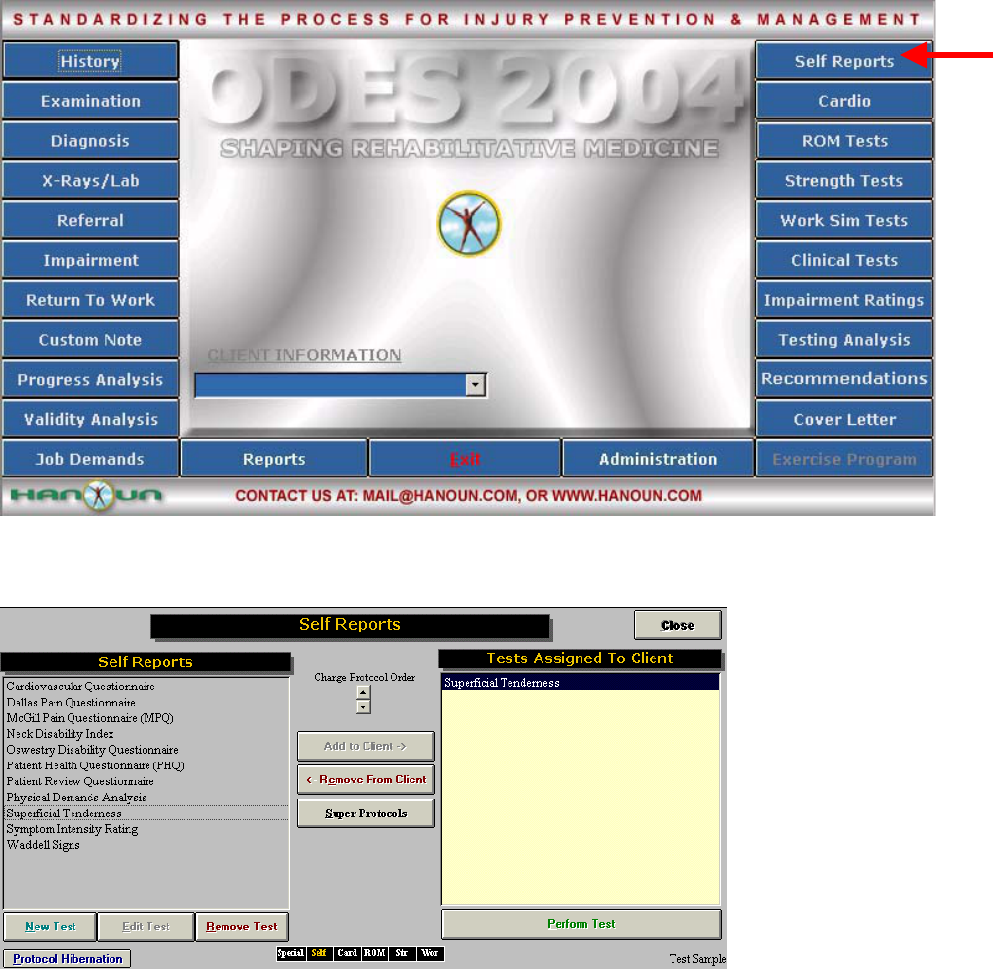
214
Within the Self Reports page, you will see Superficial Tenderness listed as an option. To assign the test
to your client, you may either double click on the protocol name, or highlight it and click Add to Client.
Once the protocol has been assigned to your client, you can either double click Superficial Tenderness
once again, or highlight the test name and click Perform Test.
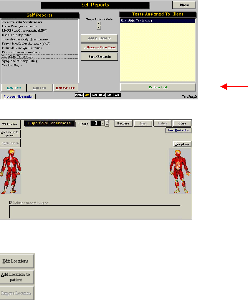
215
The Superficial Tenderness Testing page will then be displayed.
These buttons (below) allow you to Edit and Add new locations to your client for testing. If you choose to
add a location to your client, you will be responsible for selecting the location and the units to be used.
You may add multiple locations to make your assessment as specific as possible.
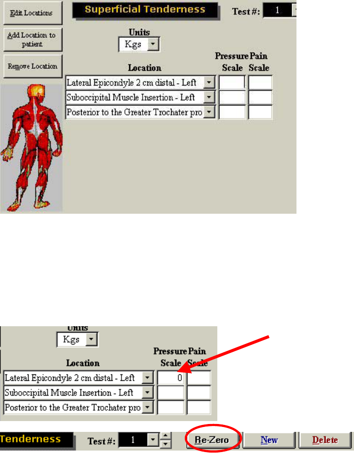
216
Results are recorded under the pressure scale heading once the test has begun. The evaluator needs to
enter the client’s pain scale rating here after each reading.
Once all of the locations have been selected and you are ready to perform a superficial tenderness test,
you must first re-zero the Algometer (apply no weight).
You may now begin testing. Make sure that your cursor is flashing in the first location underneath the
Pressure Scale heading.
You can re-zero the device at any time by clicking on the re-zero button. You may also create new trials
and delete old trials.
The ODES software also comes with a pre-programmed fibromyalgia template. To access this template,
click Templates on the superficial tenderness page.
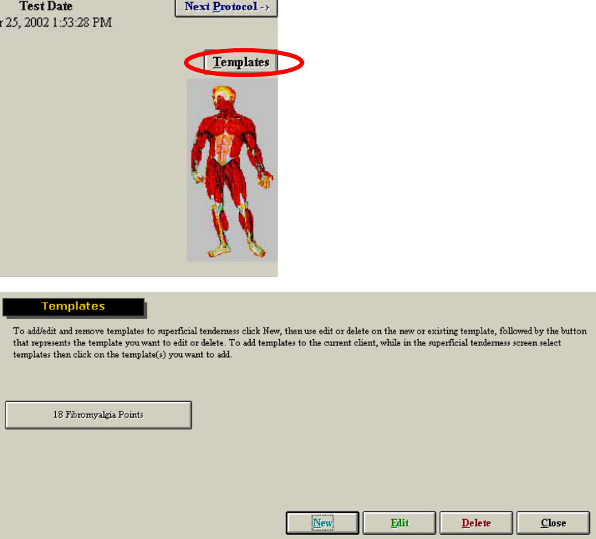
217
The template page allows you to create new templates, edit older templates and use the template for
fibromyalgia. To access the pre-programmed fibromyalgia template, click on 18 Fibromyalgia Points.
You will now enter the testing page for fibromyalgia clients.
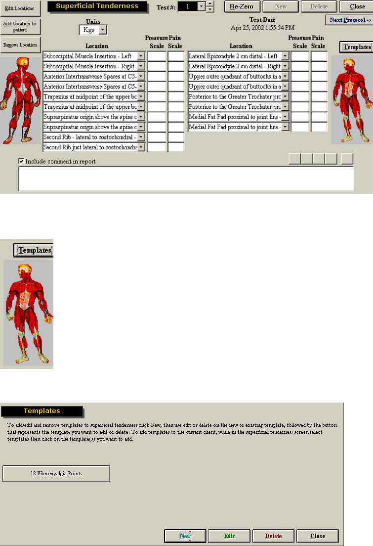
218
However, if you wish to create your own standardized protocol for superficial tenderness, you can create
a new template. To do so, click Templates, located on the superficial tenderness page.
This will bring you to the template page.
To create a new template, click New. You will now see another template button appear.
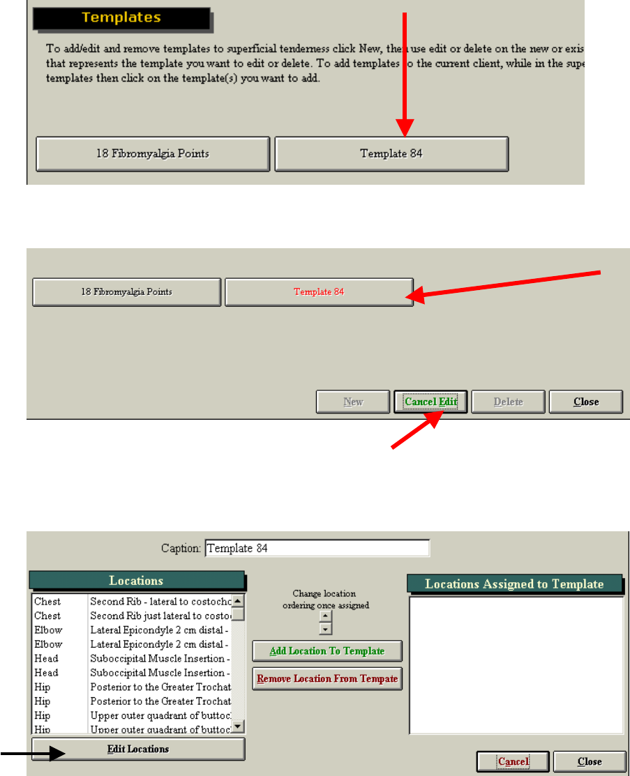
219
To edit/create this template, click Edit. You will now notice that the button changes to green ‘Cancel Edit’
and that the number template changes color to red (when you place your cursor on it).
Click on the template (in this case Template 84) to begin customizing your own protocol. The following
page will be displayed.
This page allows you to name the protocol, add and remove locations so that you can create a custom
superficial tenderness template. If the location you wish to add is not in the current list, you may add
additional locations by clicking Edit Locations.
If you choose to add new locations (by clicking on the Edit Locations button), the following page will
appear.
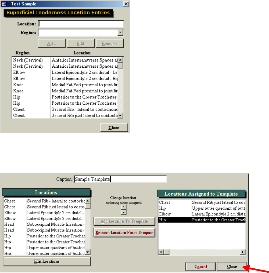
220
You can now further customize your location list.
When you have added all the locations you wish to have in your template, and placed them in the correct
order, you may click Close to complete the template.
Your template will now appear with the correct title. To finish template creation and to view your new
template, click Cancel Edit and then select your template.
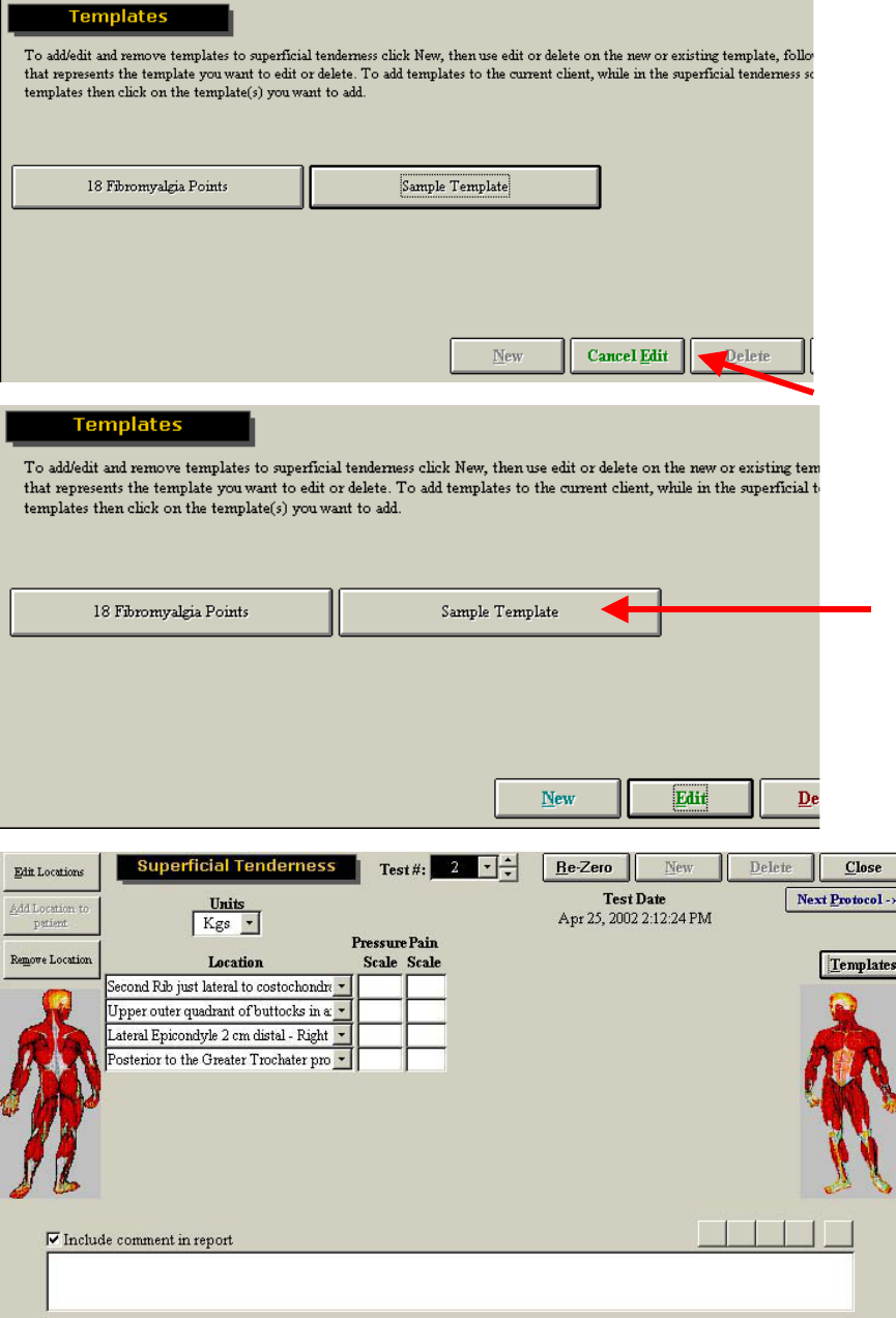
221

222
Fibromyalgia Protocol
The Fibromyalgia Protocol was developed specifically to test the 18 points used for diagnosis of this
condition.
From the main screen of ODES, select Self Reports, located in the upper right-hand corner of the page.
Within the Self Reports page, you will see Fibromyalgia Protocol listed as an option. To assign the test to
your client, you may either double click on the protocol name, or highlight it and click Add to Client.
It is important to note, that if locations are added to the client, they will
always appear with that case. The maximum number of locations that can
be added is 20. If you have already added this many locations to your
client, you will not be able to add any more. You will have to create a
second case for your client.
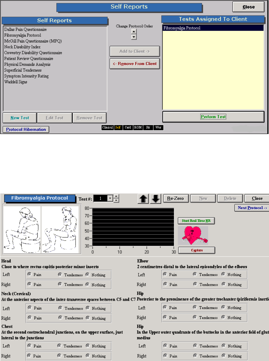
223
Once the protocol has been assigned to your client, you can either double click Fibromyalgia Protocol
once again, or highlight the test name and click Perform Test.
The Superficial Tenderness Testing page will then be displayed. Click on Start Real Time HR if you would
like to record the client’s heart rate throughout the test. Click on Capture if you would like the heart rate to
be captured as part of the Heart Rate Report.
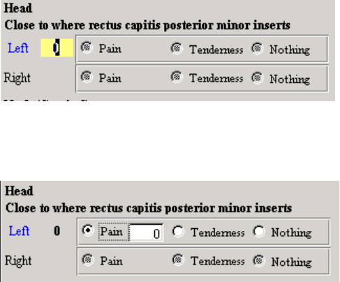
224
Double click on the location you wish to test (Left). In this example the left side of the head is about to be
tested. A yellow box will appear and the value being measured by the algometer will appear. To re-zero
the algometer click on Re-Zero.
Once the force measurement has been obtained indicate whether the client experienced pain, tenderness
or nothing. If the client experienced pain, once selected you will be prompted to enter a value for the pain
rating.
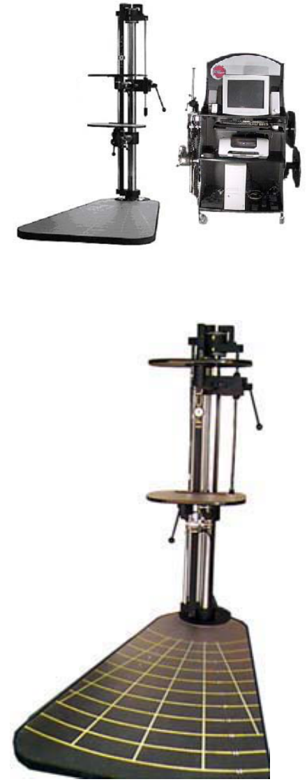
ER Platform
ER incorporates a system of fully adjustable shelves,
graded rulers and accessories to evaluate numerous
occupational task demands.
The ODES diagnostic software provides the
advantage of objective evaluation through computer
integration.
The ER Platform has many features and capabilities.
Most of the adjustments that the evaluator will perform
through the ER Platform will occur on the stand or one of
its arms.
This manual will demonstrate the versatility of the ER
Platform. The evaluator is able to combine various
hardware and software features to simulate almost any
functional task. Many tests have already been designed
and programmed into the ODES software.
The ER Platform has markers every 5 inches that can be
used independently or in combination to simulate
unlimited functional tasks.
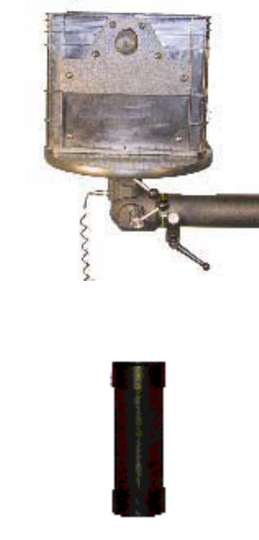
226
Standard Accessories
These are the standard accessories that are included with the ER.
2 Accessory Arms attached to the ER Platform
2 Lifting Shelves
Industry crate
Masked weights (2X15lbs, 2X5lbs, 7X10lbs)
Multiplanar accessory housing joint (single load cell)
Universal Taskmaster
Heart rate monitor (chest belt)
Heart Rate transmitter
Heart rate receiver
Goniometer (with short and long arms)
Dual Inclinometers
Handgrip dynamometer
Pinch grip dynamometer
Algometer
Strength testing pad
Narrow palmar grip handle
Wide palmar grip handle
Narrow double handle
Wide double handle
Single handle
Bar
The ER stand has two accessory arms that can be adjusted to any height, within the respective ranges,
and rotated in various planes. This enhances the versatility of the ER. All of the ER accessories can be
attached to the arms, to create tasks as individualized as the person who is being assessed.
Masked Weights
The weights can be added to the crate progressively to increase a task demand during functional testing.
Different colors at the ends of the weights indicate the weight amounts.
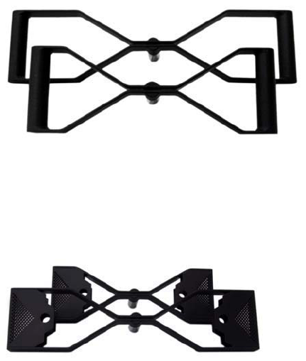
227
The labels are color coded as follows:
Color Weight
Yellow 5 lbs.
White 10 lbs.
Red 15 lbs.
Narrow and Wide Handles
The narrow and wide handles can be used for push, pull, static lift assessment, or customized tests.
Protocols preprogrammed into ODES indicate to the evaluator when to use these handles; however,
customized assessment protocols may be developed.
Narrow and Wide Palmer Grip Handles
The narrow and wide palmar grip handles can be used instead of gripping bars for push, pull, static lift
assessment, or customized tests where the hands are in the palmar grip position.
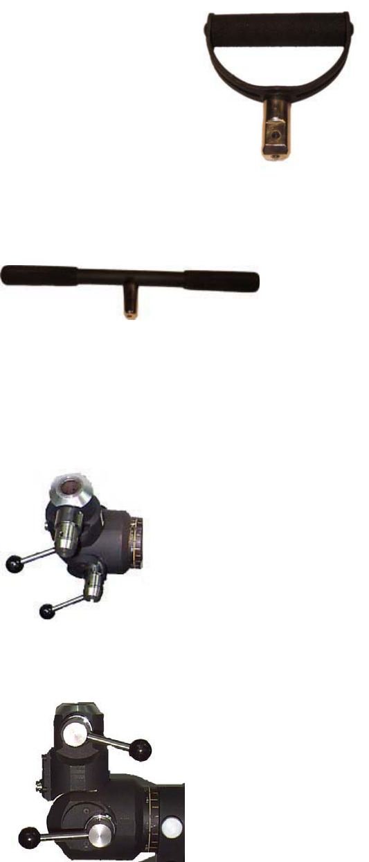
228
Single Handle
The single handle can be used for many one-handed or task-specific activities.
Straight Bar
The straight bar can be used as an alternative to the double handles or during customized tests that
require working with a bar or similar object(s).
Multiplanar Accessory Housing Joint
All accessories are attached to the ER arms through the Multiplanar
Accessory Housing Joint. Prior to attaching or removing any accessories,
become familiar with the components of the Multiplanar Accessory Housing
Joint.
The Multiplanar Accessory Housing Joint can be attached to the upper or
lower arm of the ER. It contains a load cell, which measures forces applied
through many of the ER accessories.
The Multiplanar Accessory Housing Joint includes a unique hinge joint in
its design. This joint, coupled with the Multiplanar Accessory Housing
Joint’s ability to rotate in horizontal planes parallel and perpendicular to
the client, allows for limitless testing possibilities.
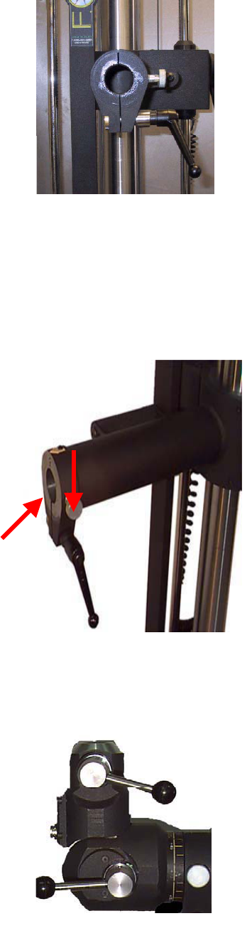
229
When facing the ER Stand, located on the right hand side of the upper or lower ER arm is a short black
handle. Above this handle is a round silver pin. These two components are used to attach the Multiplanar
Accessory Housing Joint to either of the ER arms.
Attaching the Multiplanar Accessory Housing Joint
1. Locate the short black handle on the right-hand side of the upper
or lower ER arm. The right side refers to the right when facing the
ER stand.
2. Grip the handle and rotate it approximately ¼ turn in a counter
clockwise direction. If this handle is overturned it will disengage and
fall off the ER arm. A ¼ turn is all that is necessary when attaching
the Multiplanar Accessory Housing Joint.
3. Locate the round silver pin (red arrow) above the black handle.
Pull the pin outward (further to the right) and twist it gently in any
direction.
4. Identify the cylinder at the end of the Multiplanar Accessory
Housing Joint.
5. Insert this cylinder into the hollow end of the ER arm.
6. Relocate the silver pin at the end of the accessory arm and twist it
gently until it clicks. This sound indicates that the pin has returned
to its locked position. Note that the pin may be turned in any
direction to lock it.
7. Relocate the short black handle and turn it slightly in a clockwise direction. The handle will come to a
stop when it has locked the ER arm attachment mechanism.
Removing the Multiplanar Accessory Housing Joint
1. Locate the short black handle on the end of the upper or lower ER
arm.
2. Turn the handle slightly in a counter clockwise direction. Only a ¼
turn is necessary. Overturning the handle may cause it to fall off.
3. Locate the round silver pin above the short black handle. Pull the
pin outward (further to the right) and twist it in any direction slightly.
This will unlock the attachment mechanism.
4. Grip the Multiplanar Accessory Housing Joint firmly and pull it out
of the accessory arm.
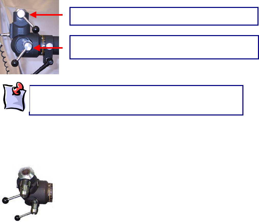
230
Once the Multiplanar Accessory Housing Joint is attached to either of the ER arms, any of the standard
accessories can be attached to it. When facing the ER Stand, with the Multiplanar Accessory Housing
Joint inserted, there will be two handles on the right hand side of Multiplanar Accessory Housing Joint.
Attaching and removing the ER Accessories
The figure below is of the Multiplanar Accessory Housing Joint, when viewed from the top. The front of
the Multiplanar Accessory Housing Joint can be identified by a cord, which exits near the hinge of the
joint. This cord attaches to the ER Data Acquisition Box, to register test results obtained when using the
load cell.
Inserting an accessory into the Multiplanar Accessory Housing Joint
Locate the top handle on the right side of the Multiplanar Accessory Housing Joint. The right side refers
to the side of the stand when viewing it from the front (i.e. the viewer’s right side).
Give the handle an approximately ¼ turn in a counterclockwise direction. This will loosen the Multiplanar
Accessory Housing Joint attachment mechanism.
The handle on top is used when attaching and removing the various
accessories.
The handle on the bottom is used when rotating the Multiplanar Accessory
Housing Joint in a vertical plane, perpendicular to the floor. The function of this
handle will be discussed later.
When using the short black handle at the end of the accessory arms, ensure that the
handle is not overturned in a counterclockwise direction. Overturning will cause the
handle to unscrew and fall off the accessory arm. When turning the handle in the
counterclockwise direction to unlock it, only a ¼ turn is necessary.
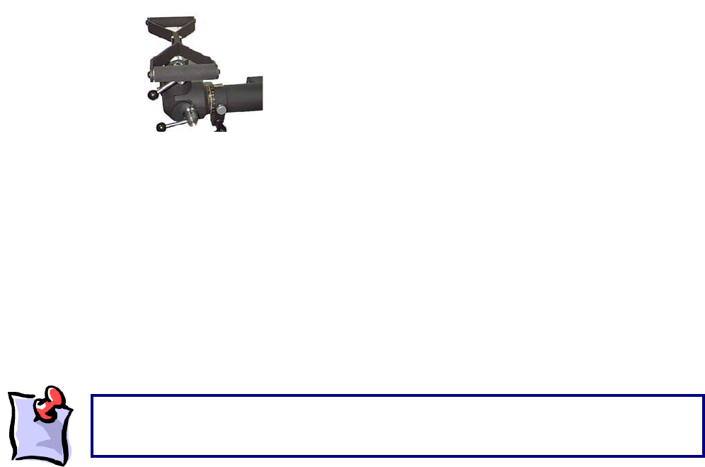
231
Grip the handle, and pull it outward (further to the right), while maintaining a firm grip on it. This will unlock
the accessory housing mechanism, by creating a space in the slot at the end of the Multiplanar Accessory
Housing Joint. While holding the handle in this position, gently twist it in any direction. This will keep the
handle in an unlocked position while you insert an accessory.
Select the accessory to be attached. On the end of the accessory there is a flattened side and a slightly
rounded side.
Insert the accessory into the opening at the top of the Multiplanar Accessory Housing Joint, with the flat
side of the accessory facing to the right (the side with the handle).
Grip the handle on the right-hand side of the Multiplanar Accessory Housing Joint and turn until a clicking
sound is heard. This indicates that the handle has locked into the accessory. Now turn the handle in a
clockwise direction, until it firmly secures the accessory into the Multiplanar Accessory Housing Joint
mechanism.
Grip the accessory and shake it back and forth. The accessory should be firmly inserted, and not be
loose in any way.
Removing an accessory from the Multiplanar Accessory Housing Joint
Locate the top handle on the right side of the Multiplanar Accessory Housing Joint.
Give the handle an approximately ¼ turn in a counterclockwise direction.
Grip the handle, and pull it outward (further to the right), while maintaining a firm grip on it, then turn it
gently in any direction. This will unlock the accessory from the housing mechanism as well as maintain
the space in the slot at the end of the Multiplanar Accessory Housing Joint.
Grip and pull the accessory until it separates from the Multiplanar Accessory Housing Joint mechanism.
ER Shelves
The ER system comes with two shelves to be used during a variety of functional tests. Each of the two
shelves has a different attachment mechanism.
One of the shelves has an end that is similar to the end of all other accessories. It is therefore referred to
as the Accessory Shelf. This shelf is used as an accessory during functional tests and attaches directly
Prior to performing any testing on clients, ensure that the Multiplanar Accessory Housing Joint
is securely attached to the upper or lower accessory arm, and that any attachment used is
firml
y
secured to the accessor
y
housin
g
mechanism.
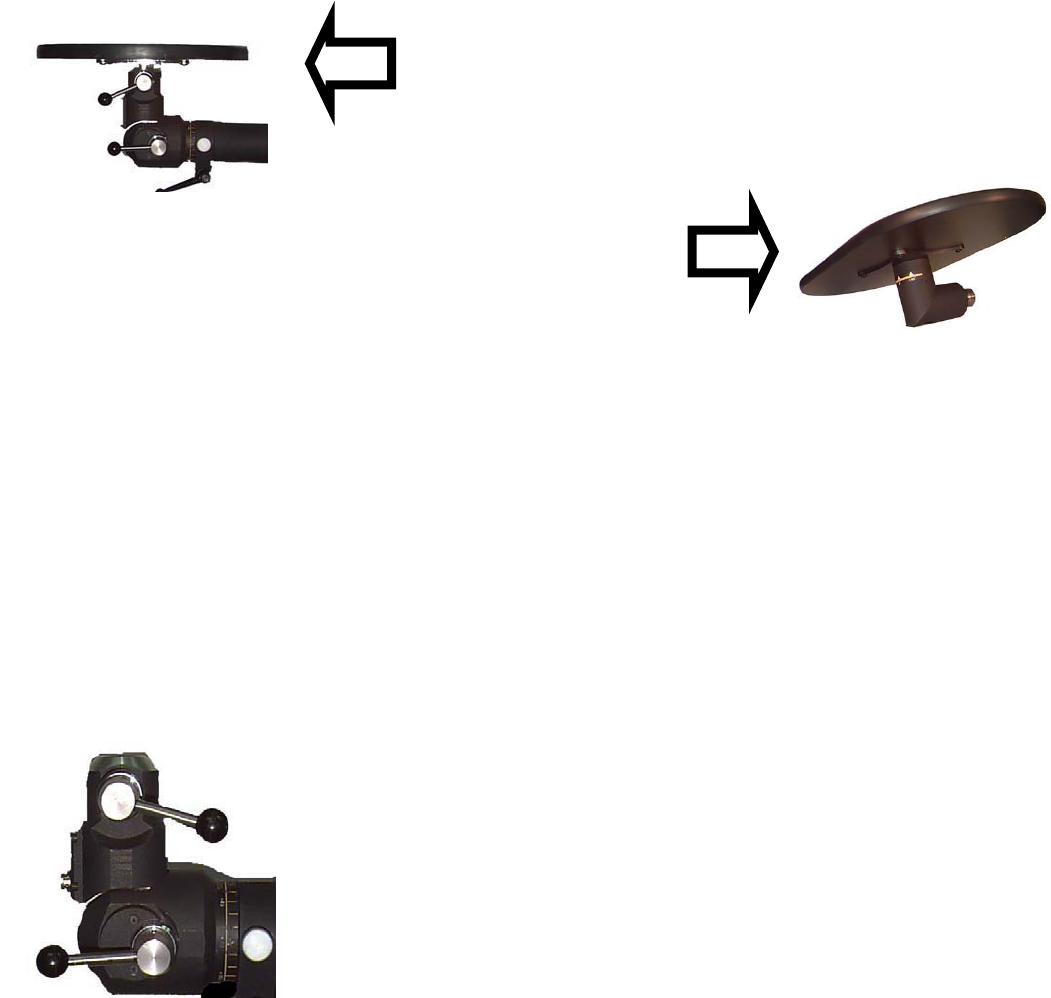
232
into the Multiplanar Accessory Housing Joint. It can be used to measure force during lifting, carrying or
other simulated tasks using the shelf..
The second shelf has an attachment at its base and can be inserted directly into either the upper or lower
accessory arm of the ER. This shelf is inserted into the accessory arms of the ER in the exact same
manner that the Multiplanar Accessory Housing Joint is inserted into the ER arms. Since this shelf is not
attached to the Multiplanar Accessory Housing Joint, it is unable to measure force. This shelf is referred
to as the Independent Shelf.
Both shelves have a safety strip at one end. This strip acts as a stopper for objects or weights placed on
the shelf during testing, preventing the object or weight from falling off.
Attaching the Accessory ER shelf
Attach the Multiplanar Accessory Housing Joint to either the upper or lower accessory arm.
Locate the top handle (identified below by the arrow) on the right hand side of the Multiplanar Accessory
Housing Joint.
Gently give the handle an approximately ¼ turn in a counterclockwise direction.
Pull the handle outward (further to the right) and twist it gently. This will create and maintain a space in
the accessory housing mechanism.
Lift the accessory ER shelf and observe its end. There is a rounded side and a flattened side on the end
of the shelf. Insert the shelf with the flattened side toward the right side of the accessory housing
The accessory ER shelf
attaches to the accessory arm
through the Multiplanar
Accessory Housing Joint.
The independent ER shelf
attaches directly to the upper
or lower accessory arm.
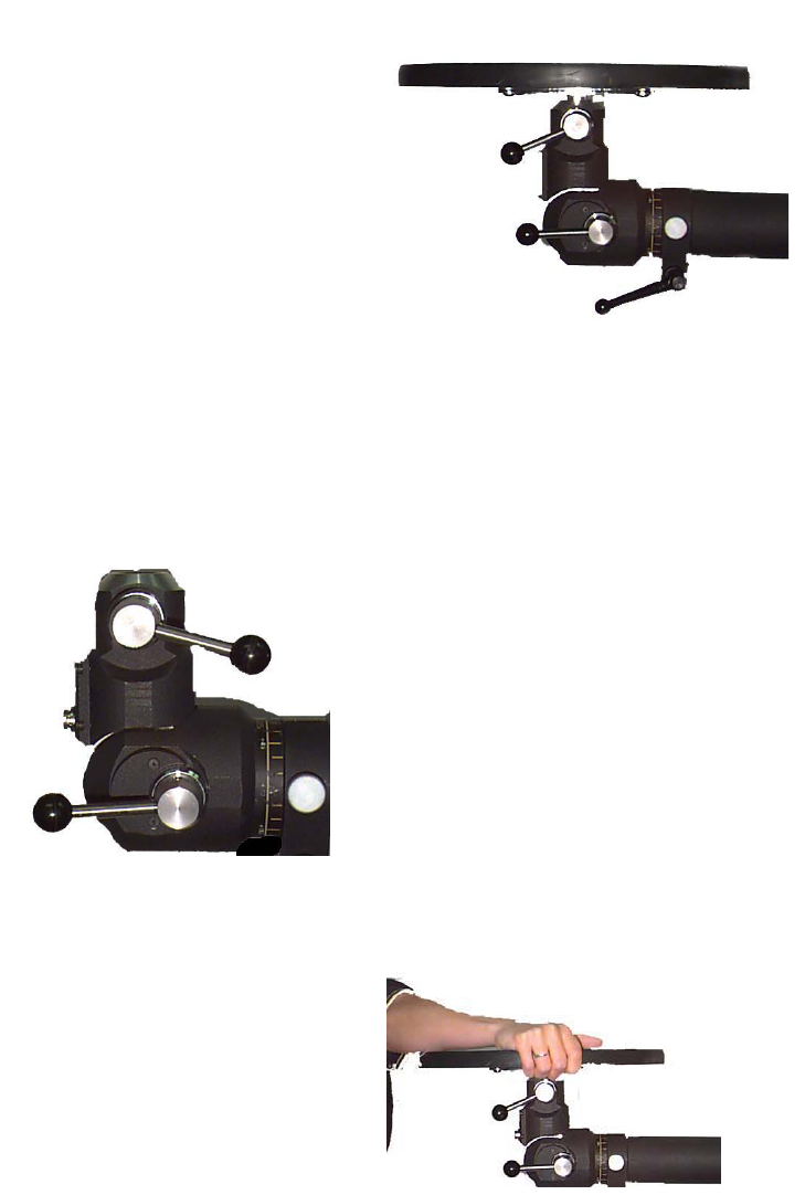
233
mechanism. The lip on the top of the shelf should be at the back to prevent the lifting crate from being
pushed off the back of the shelf.
Twist the handle on the Multiplanar Accessory Housing Joint again until a clicking sound is heard.
The shelf should be gripped with both hands and shaken gently to ensure that it is firmly secured within
the accessory housing mechanism.
Removing the Accessory ER shelf
Locate the top handle on the right-hand side of the Multiplanar Accessory Housing Joint. Loosen the
handle with a half turn in the counterclockwise direction. Pull the handle and twist a ¼ turn to release the
pin from the shelf.
The shelf should be gripped and gently rocked it back and forth until it slides out of the accessory housing
mechanism.
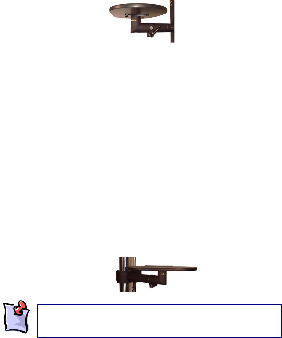
234
Attaching the Independent ER shelf
Identify the Accessory arm to which the ER shelf will be attached (upper or lower arm).Ensure that the
Multiplanar Accessory Housing Joint is not attached to the desired arm.
Locate the short black handle on the right hand side of the accessory. Grip the handle and gently give it
a ¼ turn in a counterclockwise direction. Locate the small silver pin adjacent to the short black handle.
Grip the pin and pull it outward (further to the right). Twist the pin gently in either direction. Grip the
independent ER shelf and slide its end into the opening of the accessory arm’s end. Grip the short black
handle and turn it clockwise until it locks. Grip the small round silver pin adjacent to the short handle and
twist it gently until a clicking sound is heard.
Removing the Independent ER shelf
Locate the short handle on the right-hand side of the accessory. Turn the handle gently counter clockwise
1/8th of a rotation. Locate the small silver pin adjacent to the short black handle. Grip the small silver pin
and pull it outward gently (further to the right). Twist the pin in any direction approximately ¼ turn. Grip
the Independent ER shelf with both hands and gently rock it back and forth until it slides out of the
accessory arm.
Horizontal Shelf Rotation
Whether the independent ER shelf or the accessory ER shelf is being used, the shelves can rotate in a
horizontal plane parallel to the ground. Once the shelf is attached to an ER arm, it may be rotated to the
left or right in increments of 45-degree angles. In order to rotate a shelf, follow these instructions:
Ensure that the shelf is firmly attached to an ER arm. Grip the shelf from its bottom and sides and pull
upward until a clicking sound is heard or some give is felt in the shelf. Twist the shelf in the direction of
desired rotation. A clicking sound will be heard at each 45-degree increment.
While the ER shelves can rotate 360 degrees in the horizontal plane, it is not recommended
that testing be conducted with the shelf rotated 180 degrees. This places the safety strip at
the front of the shelf, and may interfere with the safe placement of weights on the shelf
during testing.
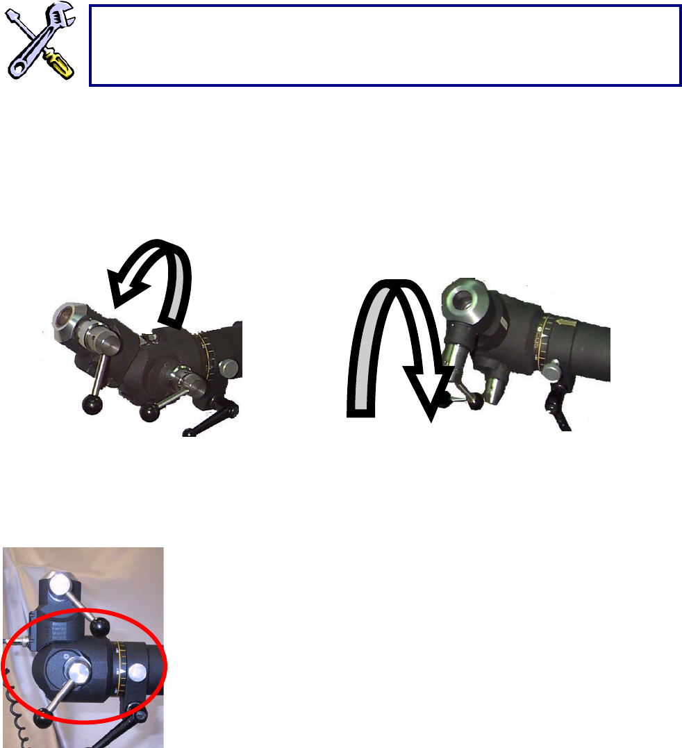
235
Changing the location and orientation of ER accessories
Rotating the Multiplanar Accessory Housing Joint
The Multiplanar Accessory Housing Joint can be rotated in
the sagittal and coronal planes. This allows you to create
task simulations as individualized as your clients’ needs.
Rotating the Multiplanar Accessory Housing Joint in the sagittal plane
Locate the handle furthest from you on the right side of the Multiplanar
Accessory Housing Joint, near its hinge (The handle closest to you was
used to insert and remove accessories).
Grip the handle and turn it in a counterclockwise direction, approximately ¼
turn. This will unlock the hinge portion of the Multiplanar Accessory
Housing Joint.
While still gripping the handle, pull it outto the right.
While maintaining the handle in an unlocked position (do not let go of the
handle), pull the Multiplanar Accessory Housing Joint forward or backward to reach the desired position.
The joint will produce a clicking sound at increments of 22.5 degrees.
To identify the angular position of the Multiplanar Accessory Housing Joint, observe the ruler on its left
side, opposite the location of the handle.
Once the Multiplanar Accessory Housing Joint is at the desired angle, release the handle back into the
locked position and turn it in a clockwise direction until it is firmly secured.
If any difficulty is experienced attaching the ER shelves, check the ends of the shelves to
ensure that the Independent shelf is not attached to the Multiplanar Accessory Housing
Joint, or that the Accessory shelf is attached directly to an ER arm.
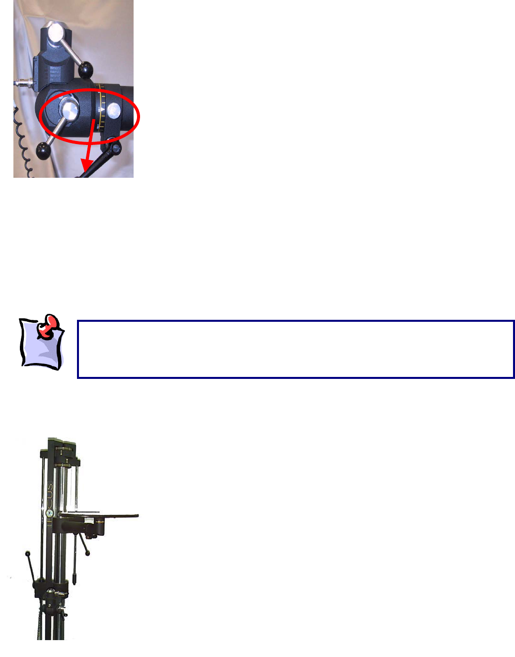
236
Rotating the Multiplanar Accessory Housing Joint in the coronal plane
Once the Multiplanar Accessory Housing Joint is inserted into the
appropriate ER arm, locate the short black handle at the end of the ER arm.
Turn the handle in a counterclockwise direction approximately ¼ rotation.
Locate the small silver pin adjacent to the short black handle.
Grip the pin and pull it out to the right.
While maintaining the pin in an outward position, twist it gently in any
direction.
Grip the Multiplanar Accessory Housing Joint firmly and rotate it in the
coronal plane to the desired angle. A ruler at the junction of the accessory
arm and the Multiplanar Accessory Housing Joint indicates the angle of
rotation. This ruler has markings at 2-degree increments and labels at 15-
degree increments.
Once the Multiplanar Accessory Housing Joint has been rotated to the desired position, grip the small
round silver pin and twist it gently until it returns to its locked position (tucked into the left). When you
rotate the Multiplanar Accessory Housing Joint to angles of 90-degree increments (i.e. 90, 180, 270, and
360 degrees) the small silver pin will click into place to lock these angles into position. For all other
angles, a click will not be heard, and the short black handle must be firmly secured to lock the Accessory
Housing Joint in position.
Grip the short black handle and turn it in a counterclockwise direction until it is firmly tightened.
Adjusting the height and orientation of the ER arms
The upper and lower arms of the ER can be moved up, down, and
rotated in a horizontal plane parallel to the ER platform.
The arms can be used during functional tests in combination or
individually. For example, when performing a dynamic lift capacity
assessment, you may attach a shelf to the lower accessory arm and
have a client lift an object from the floor to the lower shelf.
Alternatively, you may choose to attach both shelves, and have a client
lift an object from one shelf to the other. The shelves can be used to
simulate job-specific tasks facilitated by the ability to adjust the height
and orientation of both ER arms.
Prior to performing any testing, ensure that all handles are securely locked. When unlocking
handles, only ¼ turn is necessary. Overturning will cause the handle to unscrew and fall off.
When rotating the Multiplanar Accessory Housing Joint in the coronal plane, ensure that you do
not pull out the Multiplanar Accessory Housing Joint or drop it.
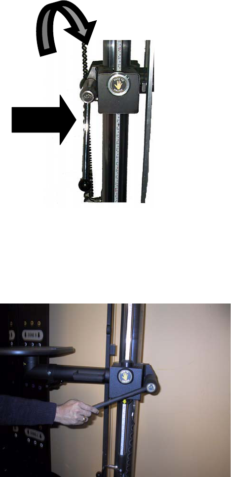
237
The Multiplanar Accessory Housing Joint, the shelves and all of the accessories can be attached to the
end of either of the ER arms.
Interchanging different ER accessories or attachments has been described in detail in the previous
section on the Multiplanar Accessory Housing Joint.
Adjusting the height of the lower ER arm
The height of the lower ER arm is controlled by two mechanisms, which
are both located on the left side of the ER stand (left is defined as
your left when you are facing the ER).
If you follow the ER arm to its attachment on the stand, you will
notice a long handle with a round black end (wide arrow). This
long handle is a general locking and release mechanism for the
lower ER arm.
If you turn the long handle clockwise you will be locking the lower
ER arm and preventing any movement from occurring. If you turn
the long handle counterclockwise you will be unlocking the lower
ER arm, which allows movements to occur.
Immediately in front of the long handle is a round button with the
words “push to unlock” and a picture of a hand on it (curved
arrow). This button is a safety locking mechanism for the lower
ER arm.
Raising or lowering the lower ER arm
Identify and grip the long handle at the end of the lower ER arm (where the arm meets the ER stand).
This long handle is located on the left side of the ER stand when you are facing the ER.
Grip the handle and turn it in a counterclockwise direction. To lock or unlock the lower ER arm
movements, it is only necessary to give the handle a ¼ turn.

238
Identify the round safety button at the end of the lower ER arm (this button has a symbol of a hand on it).
Push and hold down the safety button.
While holding down the safety button, raise or lower the ER arm to the desired position, then let go of the
button.
Grip the long handle and turn it clockwise to securely lock the lower ER arm in its new position.
Identifying the orientation and position of ER arms and accessories
The ER features a series of graded rulers, which help determine the exact orientation and placement of
the accessory arms and accessories.
When you face the ER stand you will notice a vertical ruler on the left side, which indicates the height of
the lower accessory arm.
On the right side is another vertical ruler, which indicates the height of the upper accessory arm. These
heights are automatically input into the ER software when the interface system is launched.
Both rulers feature safety stoppers at the furthest ends of rotation of the arms to prevent injury when the
assessor’s hand is placed in the vicinity of these rulers.
The round button, which reads "push to unlock", is primarily a safety mechanism that prevents
the lower ER arm from moving once it has been unlocked with the long handle. When you
press and hold this button (provided you have unlocked the ER arm using the long handle), you
will be able to raise, or lower, the ER arm. If you let go of the safety button while raising or
lowering the ER arm you will hear a grinding sound. This is like an emergency breaking
system. Try not to let go of the safety button too often or the mechanism may wear out.
When turning the long handle clockwise, its movement will eventually be blocked, because it
will be fully locked. However, when turning the long handle counterclockwise, the handle will
continue to turn and eventually unwind, falling off the ER stand. This does not happen with
proper, regular ER use, since under normal conditions, the handle only requires a slight turn
(1/4 rotation) to efficiently unlock the lower arm.
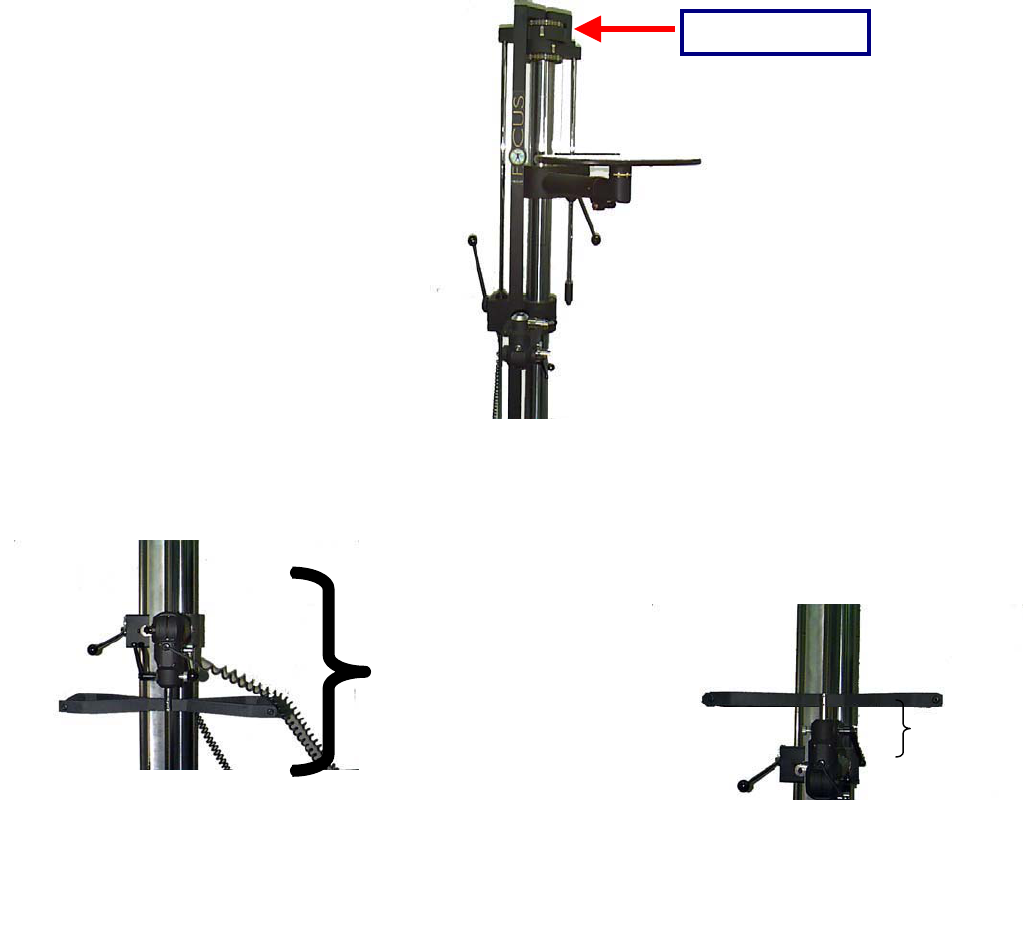
239
When you insert an accessory into the Multiplanar Accessory Housing Joint, the height of the accessory
arm is recorded as the height of the accessory (from the platform), which is 7.25 inches higher than the
actual accessory arm.
If you place an accessory in the down position, the accessory will be an extra 14.5 inches lower than the
reading on the vertical ruler (twice the height of the accessory Multiplanar Accessory Housing Joint).
Therefore, when using accessories in the down position, you must add 14.5 inches to the vertical height
to achieve the desired test height.
For example, if you use the narrow handle in the down position to perform a static lift test, and your
protocol requires a starting height of 6”, you would set the vertical height of the accessory arm to 20.5’
(=6”+14.5”).
14.5 Inches
A
ccessor
y
in the UP
7.25
Inche
Upper Arm Ruler
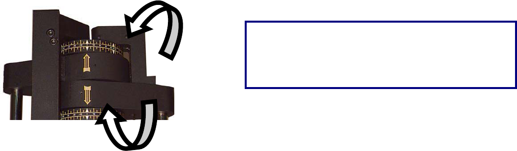
240
In addition to the graded vertical rulers, there are two graded rulers at the top of the ER stand to measure
rotation of the upper and lower arms. Each ruler provides measures in increments of 5 degrees, up to
110 degrees to the left and 110 degrees to the right.
You now have the basic information necessary in
preparation for performing functional tests and even
designing your own protocols. The following section will demonstrate how to connect the ER to the
Computer Diagnostic System, to achieve automatic data acquisition and analysis as well as automatic
report generation. Please ensure that you thoroughly read and understand the following section prior to
attempting to use the Computer Diagnostic Component. Many areas of difficulty in data acquisition arise
from incorrect connections between the software and hardware components of the ER.
The upper ruler indicates the angle of rotation of the lower
arm.
The lower ruler indicates the angle of rotation of the upper
arm.
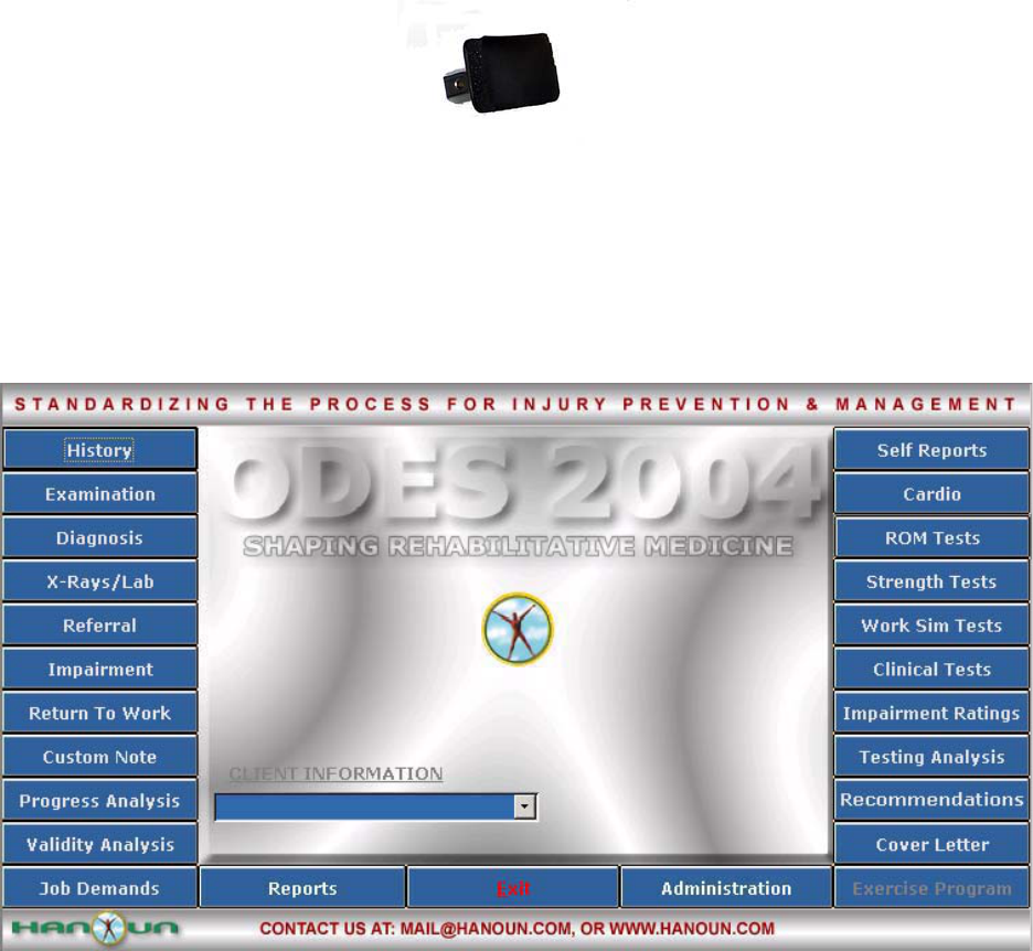
241
Isometric Strength Testing
The curved strength-testing pad is used to cushion contact surfaces on the client when assessing
strength in various postures.
Using the accessory housing joint and accessory arms, the strength-testing pad can be positioned in
various planes and angles. This allows the assessor complete versatility in the assessment of many
joints and many ranges.
To complete a static strength test using the FOCUS, click Strength Test from the main menu of ODES.
This will bring you to the Strength Test page. From here, you have access to all of the pre-programmed
strength tests. You can add tests to clients, create new custom isometric strength tests, edit tests and
delete tests.
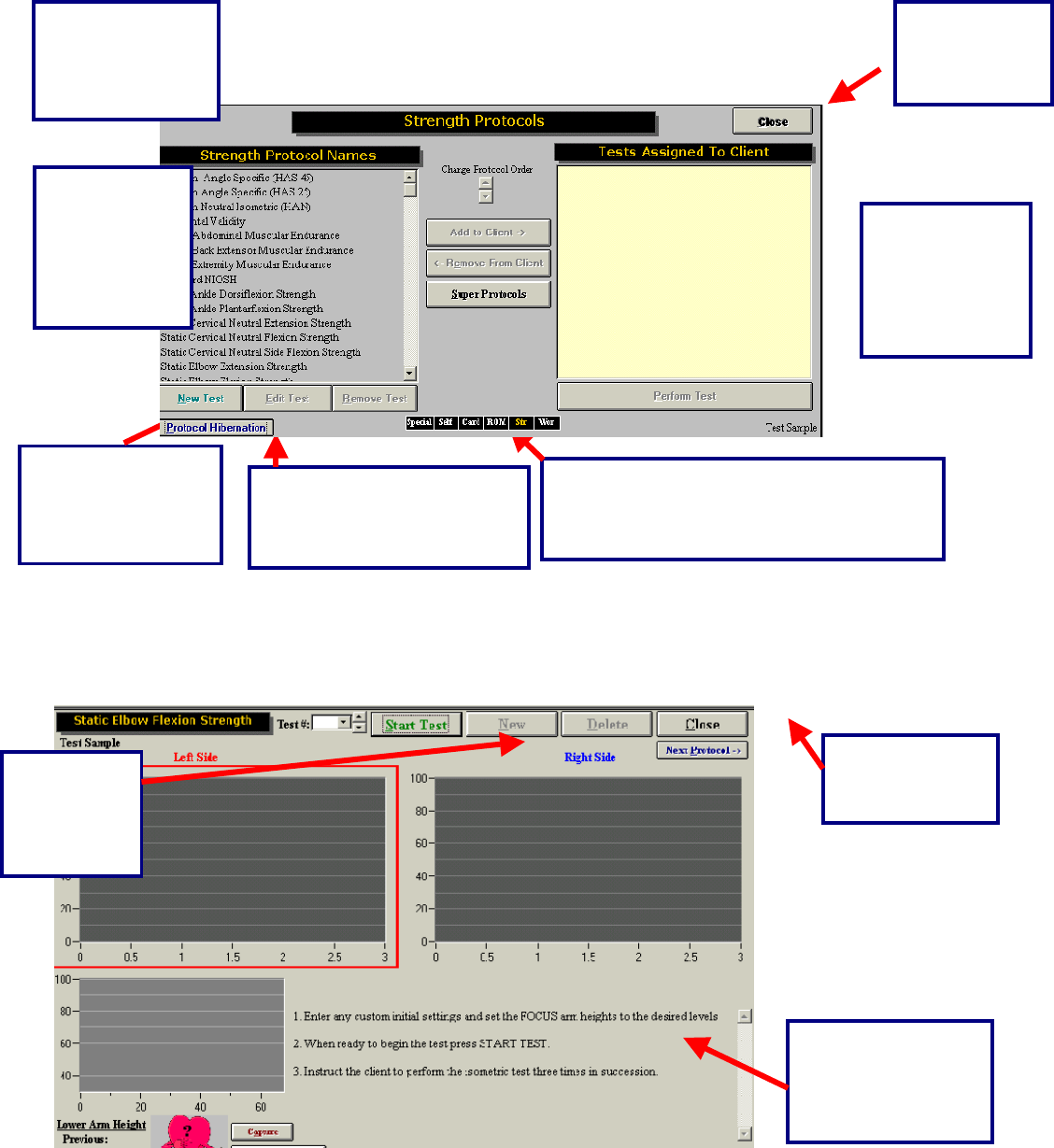
242
Once a test has been added to a client, and Perform Test has been clicked in the bottom right-hand
corner of the page (you can also double-click on the test name), your test page will appear. Below is an
example of what the typical test page looks like.
These are short cuts to return to any of the
test menu pages in ODES¥. The test menu
that is in use will appear in yellow.
Click this
button to
return to the
ODES™ main
All of the tests
that are
assigned to the
client will appear
in this area.
In order to edit,
create or remove
tests, click on the
appropriate button.
Located in this area
are the default or
custom instructions
for the
corres
p
ondin
g
test.
Click this
button to
Start the
Strength
test.
Click this button
to return to the
Strength menu.
Protocol Hibernation puts
unused protocols in storage
without removing data
Select the test
and click here
to add it to a
client, or
double click on
it.
This is a list of all
the tests found in
the Strength Test
menu.
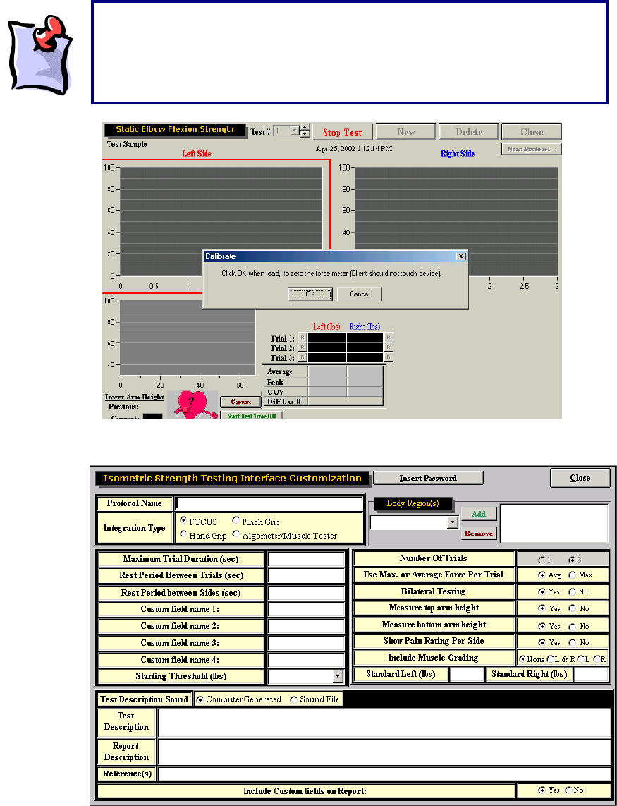
243
To create a new strength protocol, click New Test and then click Integrated Isometric Strength Protocol.
Enter in a protocol name and select the FOCUS for the Integration type. Generally for a strength test the
trial duration is 3 to 5 seconds in length with the rest between trails set to 5 seconds to allow the client’s
energy stores to build up again. A rest period of 5 seconds usually gives the evaluator enough time to set
the client up for testing on the other side. The Custom Fields allow for additional information to be
It should be noted that once the Start button is clicked, a message will appear
stating that the force meter needs to be zeroed. This is seen in the diagram
below. As there are many attachments for each load cell, ODES¥ will account
for the weight of the accessory attachment during each test. No force should
be applied to the force meter.
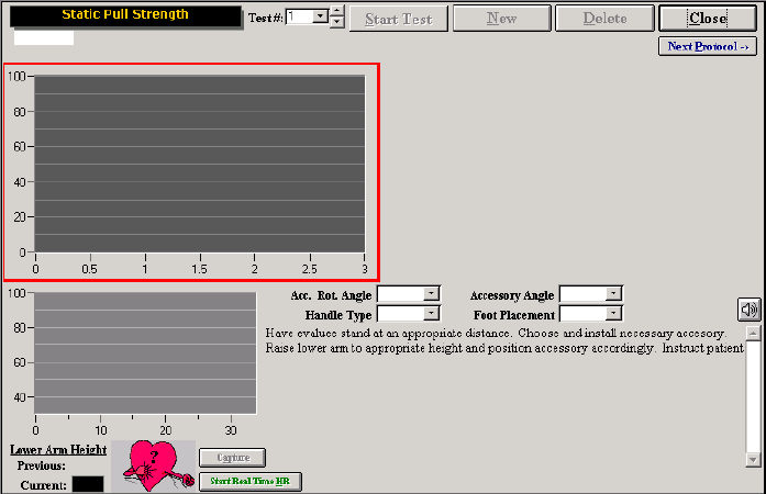
244
entered on the screen and included in the report. Select the rest of the parameters for the test. Once
Close is clicked the test will be saved and can be assigned to clients.
Work Simulation Tests
There are a number of different accessories that can be placed in a variety of positions to simulate
various work tasks.
Some preprogrammed tests, such as Static Push and Pull Strength tests require these accessories to be
placed in various positions and at various heights on the ER stand depending on the task being
simulated.
To allow the task to be replicated at a future date and to provide further details to the readers of the
report, complete the custom fields on the page. Acc. Rot. Angle refers to the accessory rotation angle,
which is the angle of the FOCUS in relation to the ER arm. The Accessory Angle refers to the angle of the
handle to the FOCUS. The Handle type refers to the attachment in the FOCUS (i.e. straight bar, single
handle etc). The Foot Placement refers to the placement of the client’s feet (i.e. staggered, together etc)
based on the task requirement (i.e. pushing a cart or push controls in a confined space).
Click Start Test to start the test. A pop-up window will remind you to ask the client to not touch the device
so the FOCUS can calibrate itself with the handle attachment.
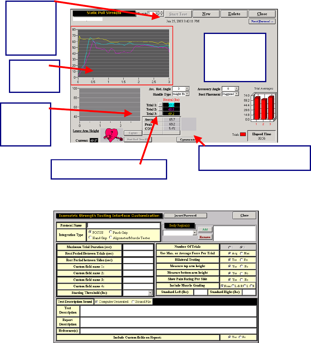
245
To create a new work simulation protocol, click New Test and then click Integrated Isometric Work
Simulation Protocol.
Enter in a protocol name and select the FOCUS for the Integration type. Set the parameters based on the
specific job task you are trying to simulate. The Custom Fields allow for additional information to be
The results are
displayed in a bar
graph. In addition,
the total elapsed
time is displayed.
The test
results are
displayed in a
line
g
ra
p
h
The trial, date
and time that
the test was
performed can
be found at the
top of the
testing page.
A
vg., peak and
COV values
are listed for
right and left
comparison.
The “R” represents a retest option for
each trial that is performed b
y
the
The comments button allows the
evaluator to enter their observations
of the test.
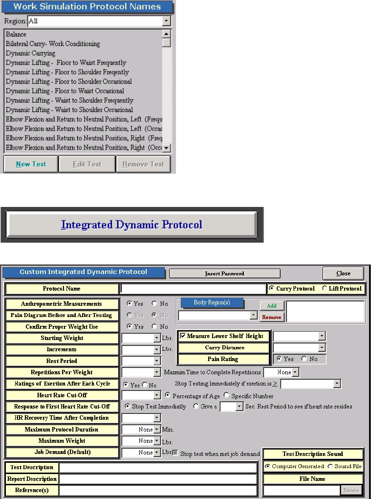
246
entered on the screen and included in the report. Select the rest of the parameters for the test. Once
Close is clicked the test will be saved and can be assigned to clients.
Integrated Dynamic Lifting and Carrying Tests
To create new lifting and carrying tests click on New under the Work Simulation section of the software.
Click on Integrated Dynamic Protocol.
The following screen will open up.
Insert a protocol name and select whether you would like the test to be a carrying or lifting test. The below
example is for a carrying protocol. Select the lower height settings and enter in the distance required to
247
carry the object. If lifting is selected, the box to include the distance for carrying changes to Measure the
Upper Shelf Height.
Select whether you would like the tests set up for anthropometric values or not. If anthropometric
measurements are selected the option of knee, knuckle, waist, elbow, shoulder, and crown are available
for selecting upper and lower shelf heights. If you do not wish to use anthropometric values click on No
and enter in specific heights in inches.
Confirming Proper Weight use refers to whether you would like the FOCUS load cell to weigh the weight
on the shelf or not. If No is selected the software will check to make sure a weight is applied to the shelf
but will not be able to determine if that is the exact weight required. If Yes is selected the load cell will
determine if the exact weight has been applied to the shelf. The evaluator must ensure that the client
remove their handles from the object being lifted entirely for a couple seconds so the software has the
opportunity to weigh the weight. You may wish to turn this function off if your client has difficulty
understanding instructions. To do this highlight the test from the list on the left hand side of the screen
under Work Sim and click on Edit and change it here.
Next select the starting weight and the increments of weight you will be increasing by for the lifting
protocol. The EPIC Lifting crate provided with the system weighs 10 pounds. If other containers are used
for lifting such as a tool box to measure unilateral lifting or carrying, weight the object first.
Include a rest period if the protocol you are using or if the job task you are simulating requires it. If Pain
Rating is set to Yes, then two boxes will appear on the test screen for the evaluator to enter in pre and
post pain ratings.
Include the repetitions per weight required before additional weight is added to the lifting container.
Include a Maximum Time to Complete Repetitions if the lifting protocol specifies that or if the job task
requires a certain amount of lifts to be completed in a specific time.
Rating of Exertions refers to the revised Borg scale that is used to determine the client’s perception as to
how heavy they feel the weight they are lifting is. It is a 10 point scale that ranges from 0=Like Nothing at
All to 10= Too Heavy. You can the select to Stop Testing Immediately if exertion is and the various
ratings for the scale are available from the drop down menu available. If this is selected in testing, once
the client has selected the rating equal to or above the limit you selected (i.e. Extremely Heavy), the test
will stop and you will be prompted with a screen asking if you to click Yes to accept the previous safe
weight or No to accept the current weight.
A heart rate cutoff can be set so that you will be warned if the client’s heart is too high. The cut-off can be
set based on a percentage of age (Maximum Age Predicted Maximum Heart Rate = 220-Age). Generally
this is set to 85% based on the American College of Sports Medicine Guidelines. If a physician for safety
concerns sets a specific heart rate cut-off, click on Specific Number and enter the value under Heart Rate
Cut-Off. Response to First Heart Rate Cut-Off allows you to set the software parameters if the heart rate
goes above the cut-off values you have selected. You can either have the test stop immediately or select
an appropriate amount of time to allow the heart rate to recover before continuing with the test. Based on
the EPIC Lifting Protocol up to a two minute rest is provided to see if the heart rate will recover.
Select Heart Rate Recovery Time After Completion if you would like the software to measure the heart
rate after the lifting test is completed to make sure the client recovered sufficiently before starting the next
test. If this option is used you must wait for the entire time selected or click on Stop before clicking on
Close or Next Protocol.
A Maximum Protocol Duration time, Maximum Weight to be lifted, or a predetermined Job Demand level
can be programmed into the software so that the test will stop once those parameters are met.
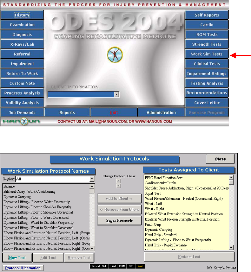
248
The ODES software has pre-programmed into it dynamic lifting and carrying tests:
Dynamic Lifting – Floor to Waist Occasional
Dynamic Lifting – Waist to Shoulder Occasional
Dynamic Lifting – Floor to Shoulder Occasional
Dynamic Lifting – Floor to Waist Frequent
Dynamic Lifting – Waist to Shoulder Frequent
Dynamic Lifting – Floor to Shoulder Frequent
Dynamic Carrying
To use these protocols or any you programmed yourself click on Work Sim from the main menu of ODES.
Select the protocol from the left hand side of the screen and add it to the client so it appears under Tests
Assigned to Client.
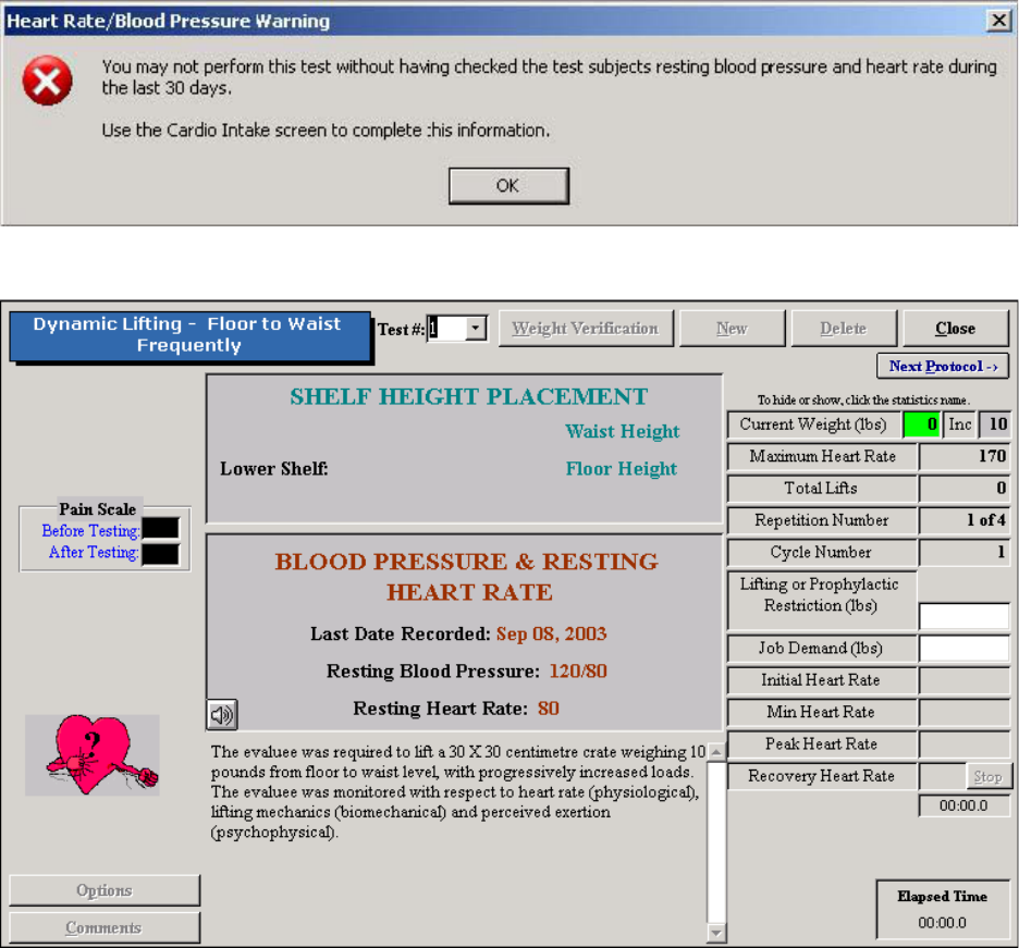
249
Either double click on the test name or highlight it and click on Perform Test to go in to the test screen.
The following screen will appear if the client’s heart rate and blood pressure have not been measured and
entered into Cardiovascular Intake. This must be done before you can continue with testing.
If this has been done the following screen will appear.
The first thing to do is to click on Weight Verification. You will be asked to take the shelf or any
attachments off the FOCUS Load Cell and click OK. You will then be prompted to attach the shelf to the
load cell and click OK. Make sure the shelf is in completely, the pin in place and tightened. Next you will
be prompted to place 20 pounds on the shelf and then click OK twice. If more than one dynamic lifting or
carrying protocol is being used for a particular client on the same day, this only needs to be done once.
For the next dynamic test selected. Click on Weight Verification and click on the bottom OK to proceed
with testing.
Once this has been completed you will be brought back to the testing screen and the Weight Verification
button changes to the Start button. Make sure the client is wearing the heart rate monitor prior to starting
the test. If you are measuring the heart rate manually, double click on the heart. Enter in the value and hit
the enter key.
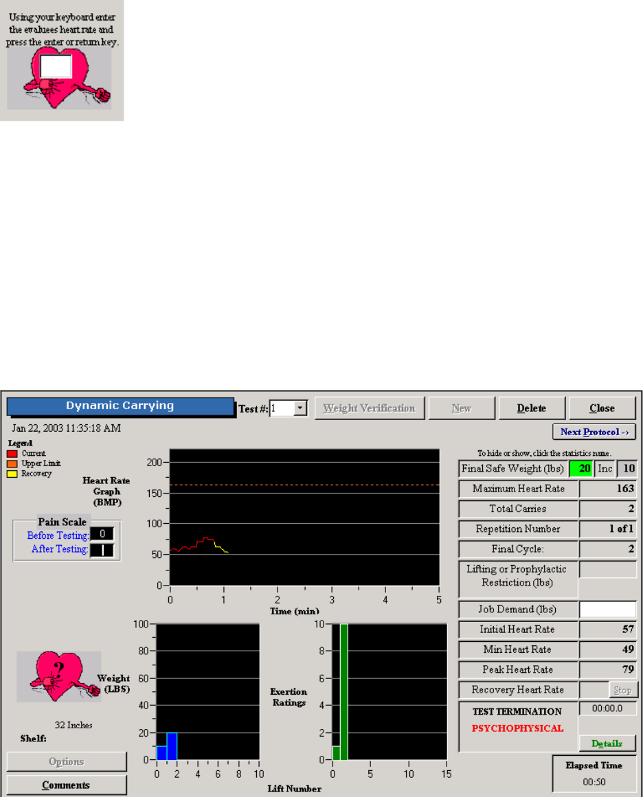
250
For the knuckle to shoulder occasional and frequent tests, the crate starts on the middle shelf with the
load cell. Once Start has been clicked on, if the correct weight is in the crate (refer to the Current Weight
box on the right hand side of the screen for more details), the computer will say continue. Once the
weight is returned to the shelf it will count the repetition. For all the other sub-tests, the crate is placed on
the lifting platform. Every time the client lifts the crate onto the load cell they must let go of the crate for a
few seconds to allow the system to weigh the crate. Once the weight has been lifted to the load cell and
taken off the computer will count the repetition.
Based on the parameters set up for the particular test (i.e. repetitions, ratings of exertion, etc) proceed
with testing. The software will alert you when the testing will stop if ratings of exertion, heart rate,
maximum protocol duration, maximum weight, or job demand level parameters have been met. To stop
the test otherwise click on Stop and a screen will appear asking for you to select the reason for stopping
the test (i.e. psychophysiological, biomechanical, etc).
Once the test has been completed the screen will look like the following.
Click on Comments to add any additional comments regarding the test.
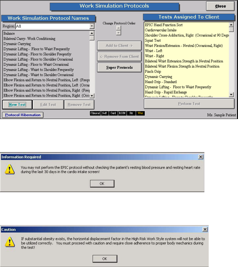
251
EPIC Lifting Capacity Protocol (Optional Upgrade)
To be able to complete this lifting protocol, the evaluator must attend an EPIC course and complete the
certification process by EPIC. As well the clinic must obtain a site license from EPIC to ensure they are
using the correct equipment. Please refer to your EPIC Training manual for more details on the specifics
on completing the EPIC protocol.
To use this component of the software, in the Work Sim section of the software, highlight the test on the
left hand side of the screen and add it to the client.
Either double click on the test name or highlight it and click on Perform Test to go in to the test screen.
The following screen will appear if the client’s heart rate and blood pressure have not been measured and
entered into Cardiovascular Intake. This must be done before you can continue with testing.
An additional warning screen will appear if the client’s body mass index is high (this is based on the
information you entered in the client’s case information) and may have an impact on their body
mechanics. This is to alert the evaluator to be cautious with testing.
The following is the test screen.
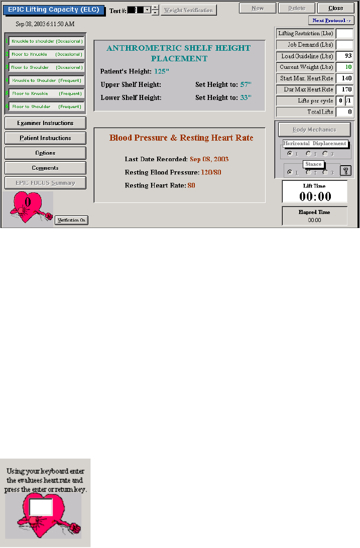
252
Determine which of the six subtests you would like to complete. Automatically all are selected when you
open the test screen. Click on them to de-select particular sub-tests. If you de-select an occasional
protocol, automatically the frequent protocol and possibly another occasional protocol will be de-selected
based on the EPIC protocol.
Before completing weight verification set the shelf heights. The shelf heights are based on the height you
entered in the client’s case information. Next, click on Weight Verification. You will be asked to take the
shelf or any attachments off the FOCUS Load Cell and click OK. You will then be prompted to attach the
shelf to the load cell and click OK. Make sure the shelf is in completely, the pin in place and tightened.
Next you will be prompted to place 20 pounds on the shelf and then click OK twice. If more than one
dynamic lifting or carrying protocol is being used for a particular client on the same day, this only needs to
be done once. If this has been done previously, click on Weight Verification and click on the bottom OK
to proceed with testing.
Once this has been completed you will be brought back to the testing screen and the Weight Verification
button changes to the Start button. Make sure the client is wearing the heart rate monitor prior to starting
the test. If you are measuring the heart rate manually, click on Options and select capturing the heart
rate manually. To enter in the heart rate manually, enter in the value and hit the enter key.
For the knuckle to shoulder occasional and frequent tests, the crate starts on the middle shelf with the
load cell. Once Start has been clicked on, if the correct weight is in the crate (refer to the Current Weight
box on the right hand side of the screen for more details), the computer will say continue. Once the
weight is returned to the shelf it will count the repetition. For all the other sub-tests, the crate is placed on
the lifting platform. Every time the client lifts the crate onto the load cell they must let go of the crate for a
few seconds to allow the system to weigh the crate. Click on the Verification On button to turn this
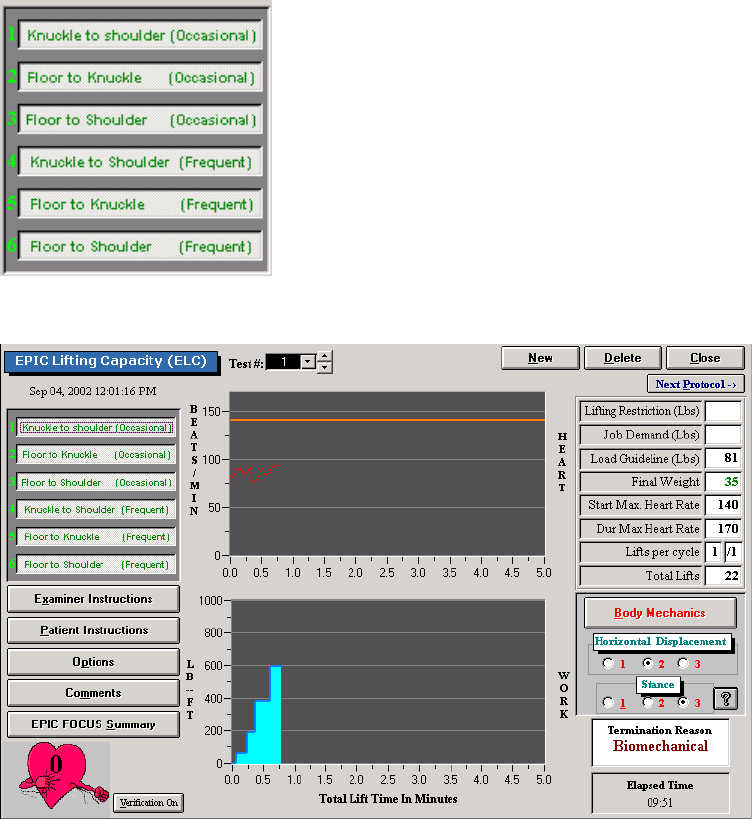
253
feature off. Once the weight has been lifted to the load cell and taken off the computer will count the
repetition.
When the weight is lifted the required times a screen will appear prompting you to enter in the client’ rate
of perceived exertion, whether they can lift the weight 8 to 12 times per day, whether they can lift more
weight, and the rating for their horizontal displacement and stance. Once that information is entered in,
click on Continue and the test will either continue or stop based on the EPIC Lifting Protocol.
To stop the test otherwise click on Stop and a screen will appear asking for you to select the reason for
stopping the test (i.e. psychophysiological, biomechanical, etc).
If the heart rate is too high the software will prompt you and two minutes will be allowed for the heart rate
return to the protocol specific value.
If during testing you decide it is not appropriate to test all the tests you may click on Start and then on the
left hand side of the screen click on the sub-test you don’t want to test. Another screen will appear asking
if you do not wish to use that sub-test. Click Yes to be taken to the next sub-test.
The following is how a completed sub-test will look.
Click on EPIC FOCUS Summary to see the information on the client’s effort during testing.
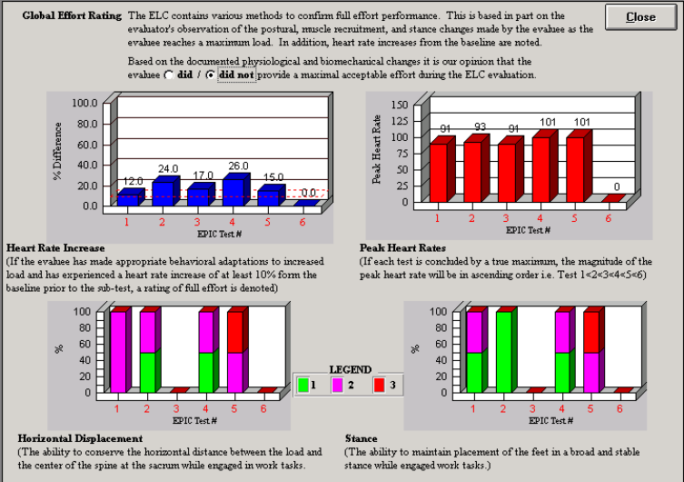
254
Based on the EPIC protocol select whether the client did or did not provide a maximal acceptable effort
during testing.
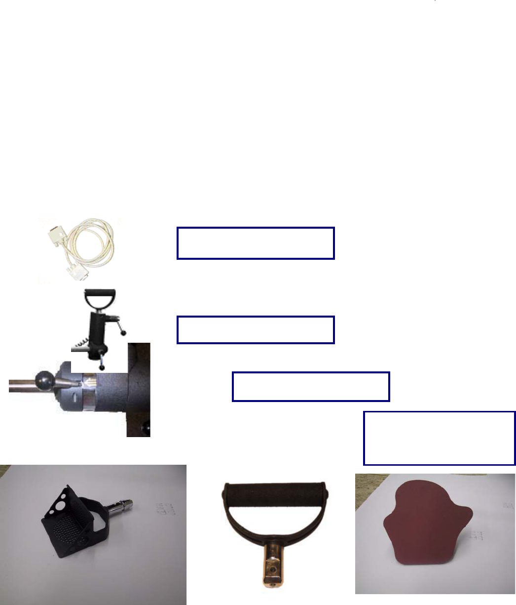
255
The Universal Task Master
The Universal Task Master (UTM) system allows the evaluator to measure both hands simultaneously
while replicating the client’s required task. The UTM allows for independent hand spread,
supination/pronation positioning, and force measurement. The UTM also rotates in the saggital and
coronal planes, allowing for extended versatility. The UTM is a powerful tool and the evaluator’s
imagination and ability to apply the numerous adjustments to replicate the task will be the only limitation
in its use.
Identification of parts associated with the UTM
Please take the time to familiarize yourself with the name and appearance of each component before
continuing through this manual or using the UTM.
Load Cells (2)
UTM Serial Cable
Force Scale Position Lock
6 UTM Handles
Two Single Handles
Two Palmar Handles
Two Box Lift Handles
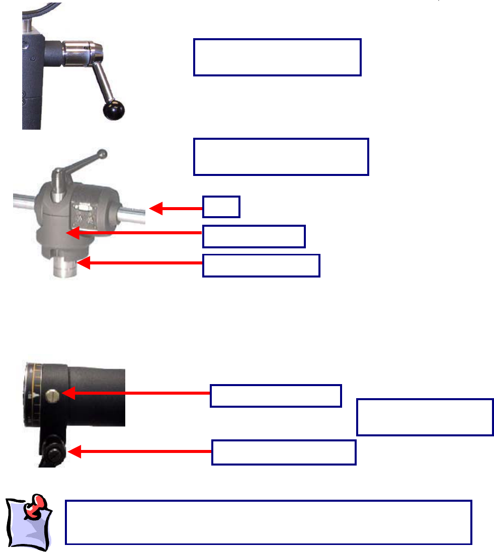
256
Inserting the UTM into the F.O.C.U.S. Arm
Place the F.O.C.U.S arm insert of the UTM (seen above) into the arm of the ER Stand that is being used
for the test (top or bottom arm).
Bar
Bar Position Locking Handle
UTM Handle Position Lock
UTM Center Housing, Bar, and
F.O.C.U.S Arm Insert
Center Housing
F.O.C.U.S Arm Insert
UTM Bar Position Locking
System
Bar Position Locking Pin
In order to rotate the bar, the locking handle will need to be loosened first (half turn
counterclockwise). In order to lock the bar into position, tighten the locking handle (turn
clockwise until ti
g
ht
)
.
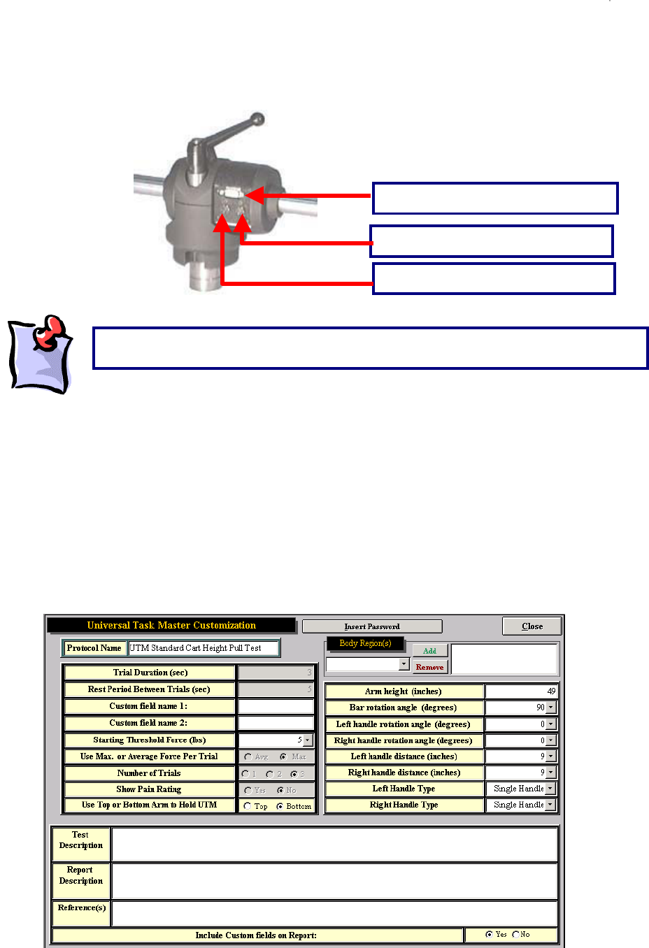
257
Connecting the UTM to the Data Acquisition Box
First connect the gray UTM integration cable from the UTM to the ‘TM’ port on the Data Acquisition Box.
Then connect the black coil cable from the left force scale to the center of the UTM and the black coil
cable from the right force scale to the center of the UTM.
Using the Universal Task Master
The software comes with two UTM tests already programmed:
UTM Standard Cart Pull Test
UTM Standard Cart Push Test
The parameters for these two tests have been set as follows:
Integration cable port
Right force scale cable port
Left force scale cable port
The black force scale cables should not cross at the center of the UTM.
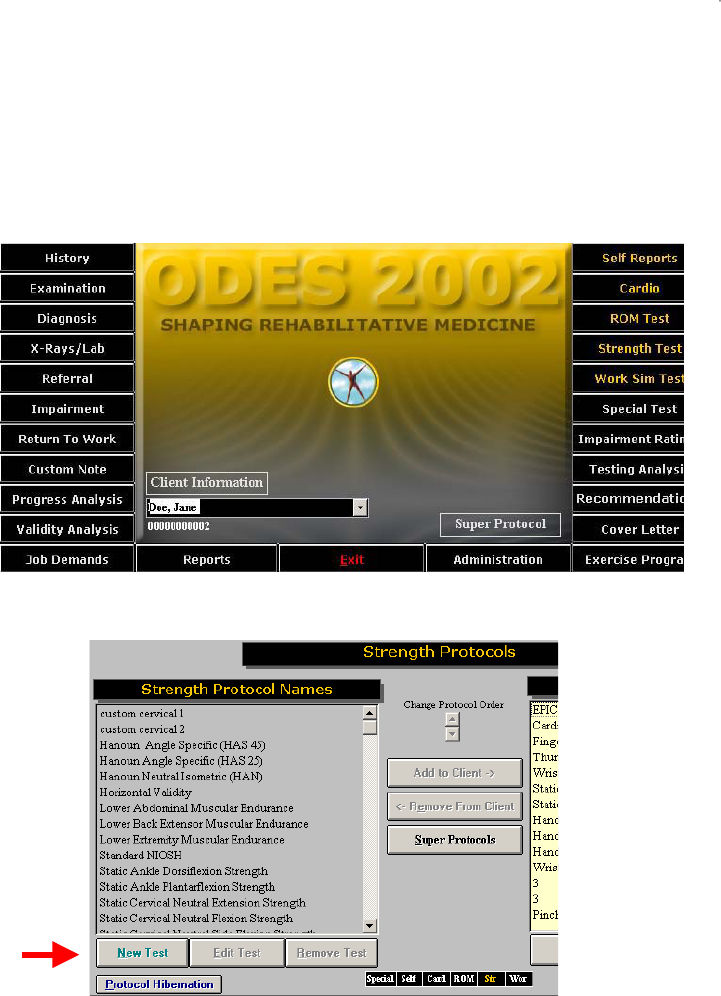
258
Designing a Custom Universal Task Master Test
The software allows for great flexibility in customizing strength and work simulation tests using the UTM
tool. A new custom integrated UTM test may be created in either the Strength Test or the Work Sim
Test functions of ODES.
Enter either the Work Sim Test menu or the Strength Test menu, whichever applies to the test to be
created, from the ODES main menu.
On the next page, click New Test.
On the next page, click Universal Task Master to customize a new test using the UTM.
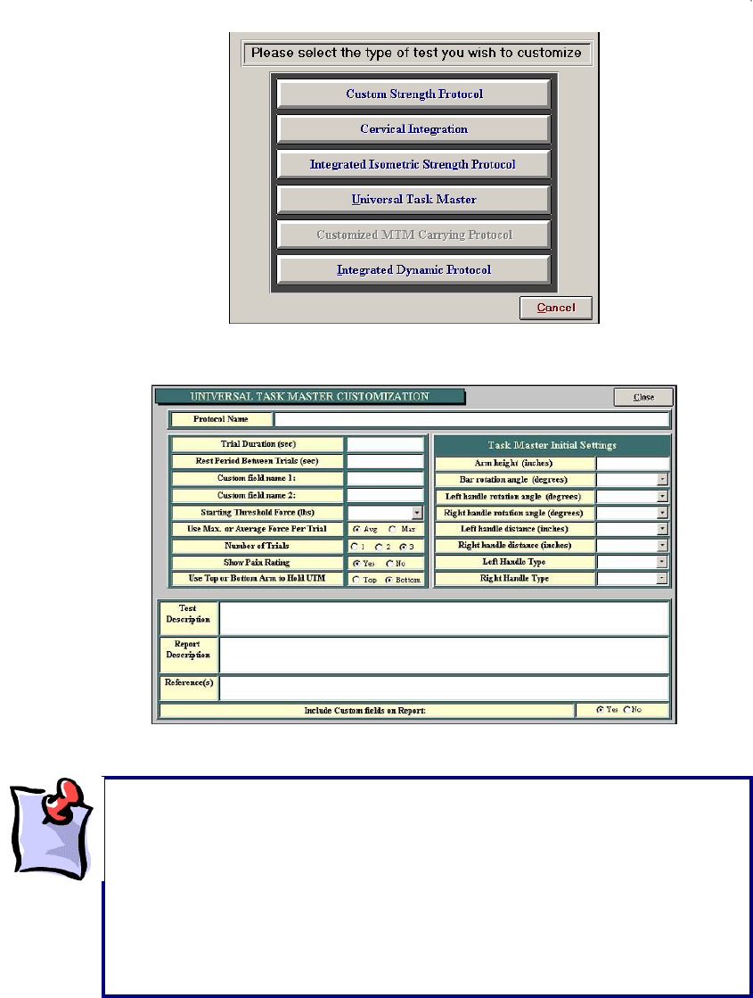
259
The next page allows you to input information required to customize a test.
Be sure that, when performing a customized test, the UTM is inserted into the arm of the ER Platform
that was chosen when creating the test (top or bottom arm). For heights of less than 46 inches, the
bottom arm is required. For heights greater than 60 inches, the top arm is required.
Important things to note:
x The starting threshold limit is the force required on at least one side to
start the test.
x When choosing between average or maximum force per trial, please
note that the average will disregard the first and last half-second of the
trial and average out the samples in between; the maximum force will
simply be the peak force applied during the trial.
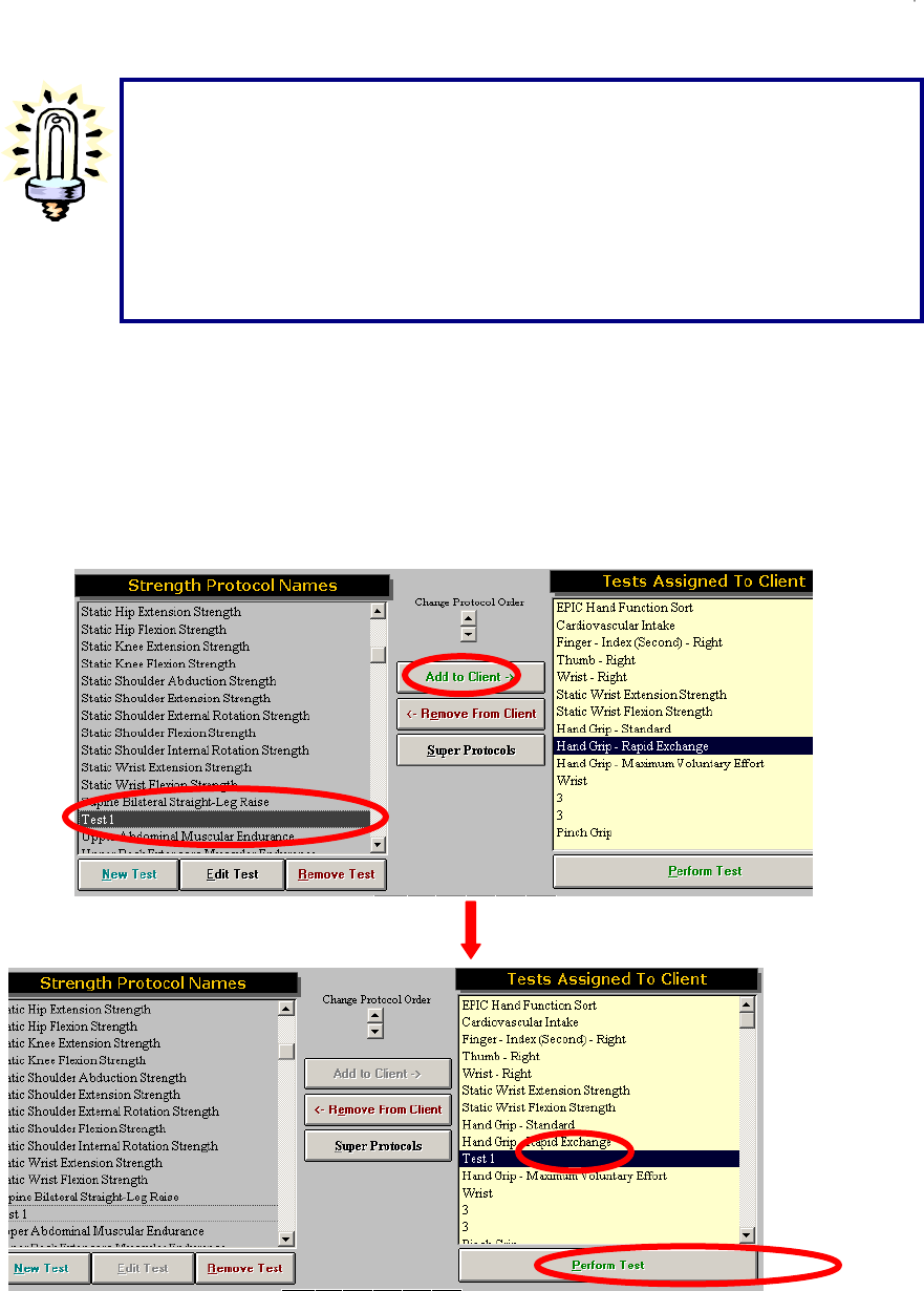
260
Once all of the information has been entered, click Close to return to the previous page. The newly
created test will now appear in the left column of the Strength Test or Work Sim Test page.
To perform this test, click on the test name to highlight it then click Add to Client in the middle of the
page. This will add the test to the Tests Assigned to Client column. Now click on the test name in the
Tests Assigned to Client column to highlight it again and click Perform Test at the bottom of the
column. This will open up the test screen and allow the newly created test to be performed.
Suggestions on Designing / Performing Custom UTM Tests
The most important rule in designing / performing a test, whether using the UTM
system or other components of ER Platform, is to try to replicate the position of the
task as closely as possible.
Replicating the job requirements will ensure an appropriate comparison of ability
to demand
,
and will more accuratel
y
determine whether or not the individual can
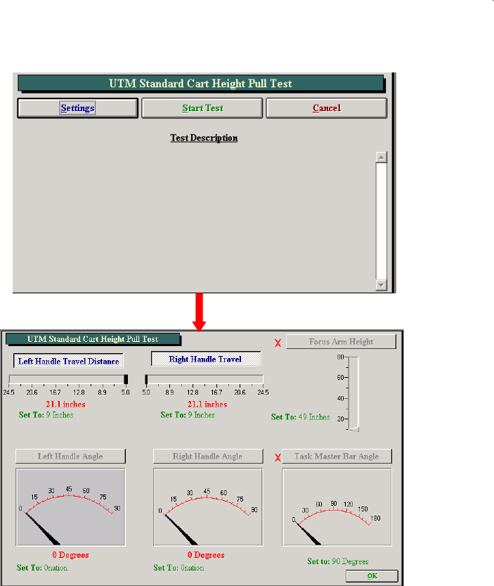
261
On the first page of the new test, click Settings . If a red ‘X’ is displayed next to an item, there is a
problem reading that device or position. See the troubleshooting section of this manual.
Set up the UTM based on the settings selected when the test was created. Once the UTM settings are
correct, click OK to go to the test screen. After clicking Start a window will pop up reminding you to make
sure the client is not touching the UTM, so the device can zero itself. Click OK and the test will begin.
During testing, you have the option of collecting real time heart rate information by clicking Start HR or by
clicking Capture HR to add the data to the Heart Rate Report.
Once the test is completed the page will look like this:
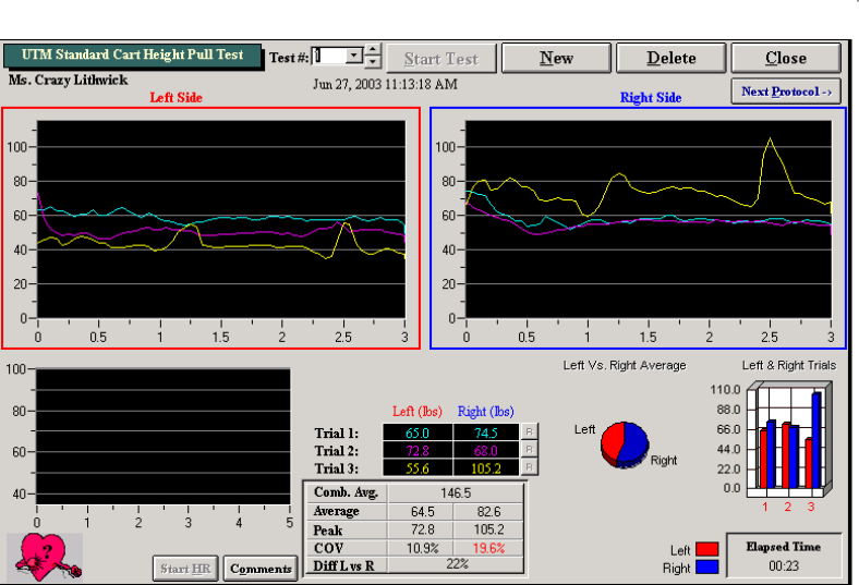
262
Once testing is complete click on the R button to the right of a trial if you need to redo that trial. Click on
Comments to add specific comments regarding the client’s performance on the test.
To start a new test click New or to delete the current test data click Delete. To close this page, click Close
or to go to a new test in sequence click Next Protocol.

263
Functional Range of Motion
The Functional Range of Motion (FROM) pegboard allows an evaluator to determine the positional
tolerances of a client. The FROM system utilizes Methods Time Measurement (MTM), allowing the
evaluator to extrapolate for occasional, frequent or constant demands.
What is Methods Time Measurement?
Methods Time Measurement (MTM) is the industrial engineering-based method for determining
time-motion performance in conjunction with work-related activities. The MTM standard offers
the means to determine an exact percentage score of performance against the most widely
recognized criteria for the assessment of time-motion activities.
The assessment of time-motion is a vital concept to many manufacturing companies throughout the
world. Without the means to assess time-motion on a standardized basis, it would be very difficult for
assembly lines to run effectively. It would also make it likely that the frequency of repetitive stress injuries
would increase significantly, as a specific means to determine whether or not a worker was being
required to perform at a level exceeding their reasonable production would be unavailable, and
guesswork would be the only substitute. The MTM standard score allows an industrial engineer to
effectively design production processes to most effectively complete job demands, while taking into
consideration and minimizing ergonomic risk factors. MTM employs the usage of time-motion units to
calculate the required performance of functional activities. The breakdown of MTM units is as follows:
1 hour = 100,000 tmu’s (time-motion units)
1 minute = 1,667 tmu’s
1 second = 27.8 tmu’s
Is MTM applicable to Functional Testing and the evaluation of individuals with disabilities?
Time-motion activities have been used in association with the evaluation of individuals with disabilities.
The MTM standard score has been the most commonly used time-motion standard to date as it provides
the most accurate and reliable means of evaluating performance. Other functional evaluation systems
that have employed the MTM standard include WEST, VALPAR, ERGOS and Lifestyle Enhancement
Systems. With respect to the evaluation of individuals with disabilities, several papers have been
published throughout the world by international associations of industrial/time-motion engineers. A copy
of some of these papers has been included with this manual.
How is MTM used in Functional Testing?
In functional capacity evaluations, the MTM standard score allows the evaluator to determine the extent
of a test subject’s capacity for positional tolerances, and determine a specific productivity equivalency for
the positional tolerance. Conventional positional tolerance protocols employed without a time-motion
equivalency fail to take into consideration the fact that individuals must demonstrate functionality within
the prescribed posture. For example, a test that asks the individual to reach overhead without the
performance of a work-related activity will not be able to discern whether or not the individual is capable
of performing gross manual or fine finger dexterity activities, elements crucial to overhead work. The
question is not whether the individual can reach overhead, but rather if the individual is capable of
performing functional activities in an overhead position. MTM also employs time-motion units to produce
a standardized and reproducible method for performance of the function making the precise repetition of
the function’s performance and instructions very important. Variations in the performance of the function
can have an impact upon the test subject’s results. In tests employing the MTM standard score, a
deviation in performance will usually lower the competitive level score of the test subject. The level of

264
employability of the test subject may also be classified using the results of the MTM-based tests . The
classifications and the associated ranges for the tests are as follows:
Exceeding Above Competitive Above 140%
Above Competitive 101-140%
Competitive 80-100%
Entry Level 70-79%
Below Competitive 0-69%
Does MTM replace the Functional Capacities Evaluator?
The use of MTM standard scores is not intended to replace the functional capacities evaluator. It creates
a standardized yet flexible basis for the administration of positional tolerance tests and the performance
of time-motion activities, as well as providing a scoring basis that is objective and ensures the
reproducibility of the test results. However, the observations of a skilled evaluator are still the most
essential part of positional tolerance functional tests. In some situations the individual may demonstrate
the ability to assume and maintain a specific posture (e.g., kneeling, crouching, etc.), but the ability to
perform at a pace commensurate with industry time-motion standards may be limited. In functional
capacity evaluations such limitations must be addressed to ensure the reliability and validity of the test
process. Even if the test subject did not require a modification in the required posture, the skilled
evaluator will still note that while the position was assumed and maintained, the performance was limited
by other physiological and/or psychological factors. Those performance limitations may include, but are
not restricted to the following: pain resulting in decreased functionality; inability to perform at a
satisfactory level within the full functional range of the physical demand; limitations in other bodily
functional areas (e.g., slowed performance in the kneeling posture due to physical limitations in
handling/fingering); severely limited cognitive processing capabilities, etc. The keen eye of the skilled
evaluator is critical in recording observed deviations from the norm and providing an interpretation for
variations in performance.
How does the MTM standard apply to the BTE Functional Range of Motion System?
The Functional Range of Motion (FROM) System has sixteen protocols for the evaluation of positional
tolerances during the performance of functional activities. Eight of the positional tolerance protocols are
designed for measurements in the occasional work category, while the other eight are designed for
measurements in the frequent category.
The number of cycles necessary to complete the occasional work demand protocols is set to most closely
approximate a 5 minute timed tolerance test period. The number of cycles necessary to complete the
frequent work demand protocols is set to most closely approximate a 20 minute timed tolerance test
period.
Separate protocols are employed in each positional tolerance for the occasional and frequent work
demand categories as the common practice of extrapolating a limited time period performance to the
frequent work demand capacity has been shown to be flawed. Tests that only require an individual to
assume a position for a period not exceeding five minutes cannot accurately measure a worker’s capacity
for endurance.
A test subject that achieves a score in the competitive range (80-100) in the frequent demand protocol for
a specific positional tolerance has demonstrated the capacity for acceptable performance over the course
of an eight hour day. It will also hold true that the test subject has successfully demonstrated the capacity
for acceptable performance with regard to the occasional work demand. A test subject achieving a score
above 100 has demonstrated the capacity for acceptable performance at or exceeding an eight hour day
equivalency.
How are the MTM test results applied to the evaluation of the patient/worker’s abilities?

265
Many large manufacturing concerns employ industrial engineers that have derived time-motion standards
for the employer’s work site. If an accurate analysis of the work determines that the employee must
perform kneeling activities on an occasional basis, but the work flow is at a rate equivalent to a 95 MTM
standard, then the evaluator has the means to determine if the worker is capable of returning to the job
and the specific demands of the workplace. Although 80 to 100 MTM is considered to be in the
competitive range, an employer with a specific MTM standard will want the worker at or above that
standard – a 95 MTM score in the example given.
For employers not using time-motion standards, the ability to quantify a worker’s capabilities within
internationally recognized time-motion standards provides a firmer basis for assessing performance than
a test where the subject is asked merely to assume a given position.
Is the method by which the test subject performs the process really that important?
The method by which the test subject performs a process is very important to the analysis of the
demonstrated ability of that individual. Time-motion standards are set assuming the specific tasks and
task elements will be performed in the most practical and efficient manner possible. For example, the
upper level reach protocol of the FROM system requires the worker to remove a peg from the unit with
one hand, transfer it to the opposite hand, and then place the peg into the corresponding hole in the next
panel. The process allows the worker to initiate removal of the next peg while the prior one is still being
placed in its proper location.
However, if the test subject were to use only one hand to transfer the first peg from one panel to the
other, the MTM score would reflect a significant negative influence. Specifically, the test subject would
lose the advantage of having both hands work in concert. Conversely, if the test subject were to use both
hands to pull two pegs out simultaneously and then move them into the appropriate holes on the
corresponding panel, the test result would likely produce a higher MTM score.
When should the process be modified, and how should this be reported?
Some individuals, due to impairment, may require modifications to the testing process. In such cases,
use the comments section of the specific test to record any variance required to accommodate the
worker’s ability to perform the test. Any decrement from the norm in the test score should also be
explained.
For example, an individual with residual effects from a closed head injury may have difficulties specifically
related to one-sided weaknesses/deficits. Although the individual may be able to kneel without difficulty
during the course of the test, the transfer of the peg from one hand to the other, as well as the placement
of the peg into the hole using the impacted extremity, may be problematic. In a situation such as this one,
it would be important to record the observation of the deficit, but also to indicate the test subject
demonstrated the ability to kneel without limitations to the lower extremities. The deficit should also be
explained as being a possible performance limitation that could affect the ability to perform activities in the
position if manual dexterity activities are required.
Should I be observing and reporting anything other than the positional tolerances in the time-motion test
process?
Although the primary positional tolerance is the specific focus of a time-motion test using the FROM
system, there are several secondary observations that can have a significant bearing upon a functional
capacity evaluation. For instance, observations related to the upper level reach activity include, but are
not limited to, the following:
the ability to work with the cervical spine in extension
the ability to work with both upper extremities through a range (chest level to full extension reach) of
motion
the ability to perform simple repetitive activities without unnecessary breaks
the ability to coordinate right and left side activities into one process

266
the possibility of tremor associated with overhead work affecting proprioception activities
Obviously, some of the most unique observations will be in the area of work conducive and non-
conducive behaviors. Pain related behaviors and the consistency of the report to the impairment are
critical to an appropriate evaluation of the test subject.
Distraction plays an important role in the FROM system’s test protocols, in order to facilitate the client’s
performance of the activity without focusing on the pain. Many individuals, when asked to perform a task,
will focus on the completion of that task. However, if an individual is not given a specific task to perform
in the associated positional tolerance, they will focus on their physical state instead, and the subjective
pain report will tend to be exaggerated. This corresponds with anecdotal reports of individuals who feel
much better after returning to work, after being in a self-limiting and restrictive environment such as the
couch during an extended course of recovery.
Some individuals are also quite competitive, and once put to a task will perform at a level that would
exceed an evaluator’s opinion of the functional capacity of the test subject absent a time-motion/task test.
Contraindications to Testing
If the test subject's initial heart rate exceeds 70% of the age-predictive maximum heart rate (220 minus
Test Subject's Age). If the test subject has a reported history of prior lower extremity or
heart/cardiovascular problems, it may be necessary to obtain a release for this type of testing.
Reason for Conclusion
1. The test subject concludes the test and reports an inability to proceed due to discomfort that makes
continuation of the test impractical.
2. The test subject's heart rate exceeds 85% of the age-predictive maximum heart rate.
3. The evaluator concludes the test as the test subject appears to be unable to continue the test due to
physical limitations.
4. The test is successfully completed
Accessing the FROM Tests
In order to access the FROM tests, a client must first be selected, or entered.
Once a client has been selected, click Work Sim Test on the ODES main page.
The following FROM Protocols are available in ODES:

267
F.R.O.M. Stooping with 36'' Displacement – Occ
PREREQUISITES
The test requires the placement of the 28" high work surface table in front of the BTE Functional Range of
Motion System. The test subject is allowed the opportunity to lean against the table while placing the pins
in the proper holes. The test subject is also advised that he/she may return to an erect posture
subsequent to the completion of a test cycle.
PROCESS
The test subject is instructed to move the five rows of pegs from Panel 2 - Zone B to the corresponding
row of holes in Panel 3 - Zone B. The transfer process requires the test subject to take the peg out of the
hole with the left hand, transfer it to the right hand while the peg is out of the hole, and then place the peg
into the corresponding hole with the right hand. The test subject commences with the highest level row
and then proceeds in order to the lowest level row. Once the fifteen pegs have been moved, the process
is completed in reverse order until all fifteen pegs are restored to their original position. This constitutes
the completion of one cycle. The test is concluded when a total of five cycles are completed.
F.R.O.M. Stooping with 36'' Displacement – Freq
PREREQUISITES
The test requires the placement of the 28" high work surface table in front of the BTE Functional Range of
Motion System. The test subject is allowed the opportunity to lean against the table while placing the pins
in the proper holes. The test subject is also advised that he/she may return to an erect posture
subsequent to the completion of a test cycle. The test subject is also advised that a ten second rest
period is provided after the completion of each five cycles until the test is completed.
PROCESS
The test subject is instructed to move the five rows of pegs from Panel 2 - Zone B to the corresponding
row of holes in Panel 3 - Zone B. The transfer process requires the test subject to take the peg out of the
hole with the left hand, transfer it to the right hand while the peg is out of the hole, and then place the peg
into the corresponding hole with the right hand. The test subject commences with the highest level row
and then proceeds in order to the lowest level row. Once the fifteen pegs have been moved, the process
is completed in reverse order until all fifteen pegs are restored to their original position. This constitutes
the completion of one cycle. The test is concluded when a total of twenty cycles are completed.

268
F.R.O.M. Stooping – Occ
PREREQUISITES
The test subject is advised that he/she may return to an erect posture subsequent to the completion of a
test cycle.
PROCESS
The test subject is instructed to move the five rows of pegs from Panel 2 - Row 2 - Zone C through Panel
2 - Row 1 - Zone B to the corresponding row of holes in Panel 3. The transfer process requires the test
subject to take the peg out of the hole with the left hand, transfer it to the right hand while the peg is out of
the hole, and then place the peg into the corresponding hole with the right hand. The test subject
commences with the highest level row and then proceeds in order to the lowest level row. Once the
fifteen pegs have been moved, the process is completed in reverse order until all fifteen pegs are
restored to their original position. This constitutes the completion of one cycle. The test is concluded
when a total of five cycles are completed.
F.R.O.M. Stooping – Freq
PREREQUISITES
The test subject is advised that he/she may return to an erect posture subsequent to the completion of a
test cycle. The test subject is also advised that a ten second rest period is provided after the completion
of each five cycles until the test is completed.
PROCESS
The test subject is instructed to move the five rows of pegs from Panel 2 - Row 2 - Zone C through Panel
2 - Row 1 - Zone B to the corresponding row of holes in Panel 3. The transfer process requires the test
subject to take the peg out of the hole with the left hand, transfer it to the right hand while the peg is out of
the hole, and then place the peg into the corresponding hole with the right hand. The test subject
commences with the highest level row and then proceeds in order to the lowest level row. Once the
fifteen pegs have been moved, the process is completed in reverse order until all fifteen pegs are
restored to their original position. This constitutes the completion of one cycle. The test is concluded
when a total of twenty cycles are completed.

269
F.R.O.M. Upper Level Reach – Occ
PREREQUISITES
The test subject is asked to stand next to the side panel of the BTE Functional Range of Motion System
and raise his/her right arm with fingers extended to the highest level of the test apparatus while remaining
with both feet flat on the floor. The highest row reached with the distal tip of the middle finger exceeding
the top of the peg hole will be the highest row used during the evaluation. If the fingertip does not exceed
the top of the peg hole, the next highest row is used. The height of the top row used must be recorded in
the comments section.
PROCESS
The test subject is instructed to move five rows of pegs from Panel 1 to the corresponding row of holes in
Panel 2. The transfer process requires the test subject to take the peg out of the hole with the left hand,
transfer it to the right hand while the peg is out of the hole, and then place the peg into the corresponding
hole with the right hand. The test subject commences with the highest level row and then proceeds in
order to the lowest level row. Once the fifteen pegs have been moved, the process is completed in
reverse order until all fifteen pegs are restored to their original position. This constitutes the completion of
one cycle. The test is concluded when a total of five cycles are completed.
F.R.O.M. Upper Level Reach – Freq
PREREQUISITES
The test subject is asked to stand next to the side panel of the BTE Functional Range of Motion System
and raise his/her right arm with fingers extended to the highest level of the test apparatus while remaining
with both feet flat on the floor. The highest row reached with the distal tip of the middle finger exceeding
the top of the peg hole will be the highest row used during the evaluation. If the fingertip does not exceed
the top of the peg hole, the next highest row is used. The height of the top row used must be recorded in
the comments section.
PROCESS
The test subject is instructed to move five rows of pegs from Panel 1 to the corresponding row of holes in
Panel 2. The transfer process requires the test subject to take the peg out of the hole with the left hand,
transfer it to the right hand while the peg is out of the hole, and then place the peg into the corresponding
hole with the right hand. The test subject commences with the highest level row and then proceeds in
order to the lowest level row. Once the fifteen pegs have been moved, the process is completed in
reverse order until all fifteen pegs are restored to their original position. This constitutes the completion of
one cycle. The test is concluded when a total of twenty cycles are completed. A rest period of ten
seconds is allowed between each set of five cycles.

270
F.R.O.M. Crouching Reach – Occ
PREREQUISITES
The test subject is advised that he/she must remain in the crouching/squatting position and may touch
only one knee down to the ground after the completion of a cycle. The knee must return to the
crouch/squat position prior to the transfer of any pegs for the next cycle.
PROCESS
The test subject is instructed to move the five rows of pegs from Panel 1 - Zone C to the corresponding
row of holes in Panel 2 - Zone C. The transfer process requires the test subject to take the peg out of the
hole with the left hand, transfer it to the right hand while the peg is out of the hole, and then place the peg
into the corresponding hole with the right hand. The test subject commences with the highest level row
and then proceeds in order to the lowest level row. Once the fifteen pegs have been moved, the process
is completed in reverse order until all fifteen pegs are restored to their original position. This constitutes
the completion of one cycle. The test is concluded when a total of five cycles are completed.
F.R.O.M. Crouching Reach – Freq
PREREQUISITES
The test subject is advised that he/she must remain in the crouching/squatting position and may touch
only one knee down to the ground after the completion of a cycle. The knee must return to the
crouch/squat position prior to the transfer of any pegs for the next cycle. The test subject is also advised
that a ten second rest period is provided after the completion of each five cycles.
PROCESS
The test subject is instructed to move the five rows of pegs from Panel 1 - Zone C to the corresponding
row of holes in Panel 2 - Zone C. The transfer process requires the test subject to take the peg out of the
hole with the left hand, transfer it to the right hand while the peg is out of the hole, and then place the peg
into the corresponding hole with the right hand. The test subject commences with the highest level row
and then proceeds in order to the lowest level row. Once the fifteen pegs have been moved, the process
is completed in reverse order until all fifteen pegs are restored to their original position. This constitutes
the completion of one cycle. The test is concluded when a total of twenty cycles are completed.

271
F.R.O.M. Axial Rotation – Occ
PROCESS
The test subject is instructed to move five rows of pegs from Panel 1 - Zone B to Panel 6 - Zone B. The
transfer process requires the test subject to take the peg out of the hole with the left hand, transfer it to
the right hand while the peg is out of the hole, and then place the peg into the corresponding hole with the
right hand. The test subject commences with the highest level row and then proceeds in order to the
lowest level row. Once the fifteen pegs have been moved, the process is completed in reverse order until
all fifteen pegs are restored to their original position. This constitutes the completion of one cycle. The
test is concluded when a total of five cycles are completed.
F.R.O.M. Axial Rotation – Freq
PROCESS
The test subject is instructed to move five rows of pegs from Panel 1 - Zone B to Panel 6 - Zone B. The
transfer process requires the test subject to take the peg out of the hole with the left hand, transfer it to
the right hand while the peg is out of the hole, and then place the peg into the corresponding hole with the
right hand. The test subject commences with the highest-level row and then proceeds in order to the
lowest level row. Once the fifteen pegs have been moved, the process is completed in reverse order until
all fifteen pegs are restored to their original position. This constitutes the completion of one cycle. The
test is concluded when a total of twenty cycles are completed. After each five cycles the test subject is
allowed a ten-second rest period.

272
F.R.O.M. Kneeling – Occ
PREREQUISITES
The test subject is allowed the opportunity to wear knee pads if desired. The test subject is also advised
that he/she must remain in the kneeling position during the course of the test until it is completed.
PROCESS
The test subject is instructed to move the five rows of pegs from Panel 1 - Zone C to the corresponding
row of holes in Panel 2 - Zone C. The transfer process requires the test subject to take the peg out of the
hole with the left hand, transfer it to the right hand while the peg is out of the hole, and then place the peg
into the corresponding hole with the right hand. The test subject commences with the highest level row
and then proceeds in order to the lowest level row. Once the fifteen pegs have been moved, the process
is completed in reverse order until all fifteen pegs are restored to their original position. This constitutes
the completion of one cycle. The test is concluded when a total of five cycles are completed.
F.R.O.M. Kneeling – Freq
PREREQUISITES
The test subject is allowed the opportunity to wear kneepads if desired. The test subject is also advised
that he/she must remain in the kneeling position during the course of the test for the completion of five
cycles before a ten-second rest is allowed out of the kneeling position. The rest period is allowed out of
the kneeling position after every five cycles until the test is completed.
PROCESS
The test subject is instructed to move the five rows of pegs from Panel 1 - Zone C to the corresponding
row of holes in Panel 2 - Zone C. The transfer process requires the test subject to take the peg out of the
hole with the left hand, transfer it to the right hand while the peg is out of the hole, and then place the peg
into the corresponding hole with the right hand. The test subject commences with the highest level row
and then proceeds in order to the lowest level row. Once the fifteen pegs have been moved, the process
is completed in reverse order until all fifteen pegs are restored to their original position. This constitutes
the completion of one cycle. The test is concluded when a total of twenty cycles are completed.

273
F.R.O.M. Kneeling to Standing and Back – Occ
PREREQUISITES
The test subject is allowed the opportunity to wear kneepads if desired.
PROCESS
The evaluator sets up one row of pegs in each of the lowest rows (yellow) in Panel 2 - Zone B and Panel
2 - Zone C. The test subject is instructed to move a row of pegs from Panel 2 - Zone C at the lowest row
to the next highest row directly above the row from which the activity started. The pegs will be moved to
the corresponding hole directly above. Two of the pegs must be moved with one hand and the third peg
must be moved with the opposite hand. The test subject must perform all activity in Zone C in a kneeling
posture while all activity performed in Zone B must be done in a standing posture. Once the pegs have
reached the top row in Zone B a test cycle has been completed. The test subject then proceeds to move
the pegs downward, one row at a time employing the same process. Upon reaching the lowest row of
holes in Zone C another cycle has been completed. The test is concluded when a total of seven cycles
are completed. This means the person will complete the test in a standing posture.
F.R.O.M. Kneeling to Standing and Back – Freq
PREREQUISITES
The test subject is allowed the opportunity to wear kneepads if desired.
PROCESS
The evaluator sets up one row of pegs in each of the lowest rows (yellow) in Panel 2 - Zone B and Panel
2 - Zone C. The test subject is instructed to move a row of pegs from Panel 2 - Zone C at the lowest row
to the next highest row directly above the row from which the activity started. The pegs will be moved to
the corresponding hole directly above. Two of the pegs must be moved with one hand and the third peg
must be moved with the opposite hand. The test subject must perform all activity in Zone C in a kneeling
posture while all activity performed in Zone B must be done in a standing posture. Once the pegs have
reached the top row in Zone B a test cycle has been completed. The test subject then proceeds to move

274
the pegs downward, one row at a time employing the same process. Upon reaching the lowest row of
holes in Zone C another cycle has been completed. The test is concluded when a total of twenty eight
cycles are completed. A ten second rest period is provided after the completion of each seven cycles
until the test is completed.
F.R.O.M. Standing Position – Occ
PROCESS
The test subject is instructed to move five rows of pegs from Panel 1 - Zone B to Panel 4 Zone B. The
transfer process requires the test subject to take the peg out of the hole with the left hand, transfer it to
the right hand while the peg is out of the hole, and then place the peg into the corresponding hole with the
right hand. The test subject commences with the highest level row and then proceeds in order to the
lowest level row. Once the fifteen pegs have been moved, the process is completed in reverse order until
all fifteen pegs are restored to their original position. This constitutes the completion of one cycle. The
test is concluded when a total of four cycles are completed.
F.R.O.M. Standing Position – Freq
PROCESS
The test subject is instructed to move five rows of pegs from Panel 1 - Zone B to Panel 4 - Zone B. The
transfer process requires the test subject to take the peg out of the hole with the left hand, transfer it to
the right hand while the peg is out of the hole, and then place the peg into the corresponding hole with the
right hand. The test subject commences with the highest level row and then proceeds in order to the
lowest level row. Once the fifteen pegs have been moved, the process is completed in reverse order until
all fifteen pegs are restored to their original position. This constitutes the completion of one cycle. The
test is concluded when a total of sixteen cycles are completed. The test subject is advised that a ten
second rest period is provided after the completion of each four cycles.

275
F.R.O.M. Multi-Level Axial Rotation Reach - Occ
PROCESS
The test subject is instructed to move five rows of pegs from Panel 6 – Zone A (Height Adjusted) to Panel
5 – Zone B. The five rows of pegs in Panel 5 – Zone B are then transferred directly across to Panel 6 –
Zone B. Then, the five rows of pegs in Panel 6 – Zone B are transferred to the five rows in Panel 5 –
Zone A (Height Adjusted). Finally, the five rows of pegs in Panel 5 – Zone A are transferred to the same
rows in Panel 6 – Zone A. This completes one cycle. A total of two cycles are completed for this test.
The transfer process requires the test subject, when going from left to right, to take the peg out of the hole
with the left hand, transfer it to the right hand while the peg is out of the hole, and then place the peg into
the corresponding hole with the right hand. When going from right to left, the transfer process is
reversed. The test subject commences with the lowest level row and then proceeds in order to the
highest-level row.
F.R.O.M. Multi-Level Axial Rotation Reach - Freq
PROCESS
The test subject is instructed to move five rows of pegs from Panel 6 – Zone A (Height Adjusted) to Panel
5 – Zone B. The five rows of pegs in Panel 5 – Zone B are then transferred directly across to Panel 6 –
Zone B. Then, the five rows of pegs in Panel 6 – Zone B are transferred to the five rows in Panel 5 –
Zone A (Height Adjusted). Finally, the five rows of pegs in Panel 5 – Zone A are transferred to the same
rows in Panel 6 – Zone A. This completes one cycle. A total of two cycles are completed for this test.
The transfer process requires the test subject, when going from left to right, to take the peg out of the hole
with the left hand, transfer it to the right hand while the peg is out of the hole, and then place the peg into
the corresponding hole with the right hand. When going from right to left, the transfer process is
reversed. The test subject commences with the lowest level row and then proceeds in order to the
highest-level row. The test subject is advised that a ten second-rest period is provided after the
completion of each two cycles.
Once a test has been added to a client, and Perform test has been selected in the bottom right hand
corner of the page (you can also double click the test name), your test page will appear. Below is an
example of what the typical test page should look like.
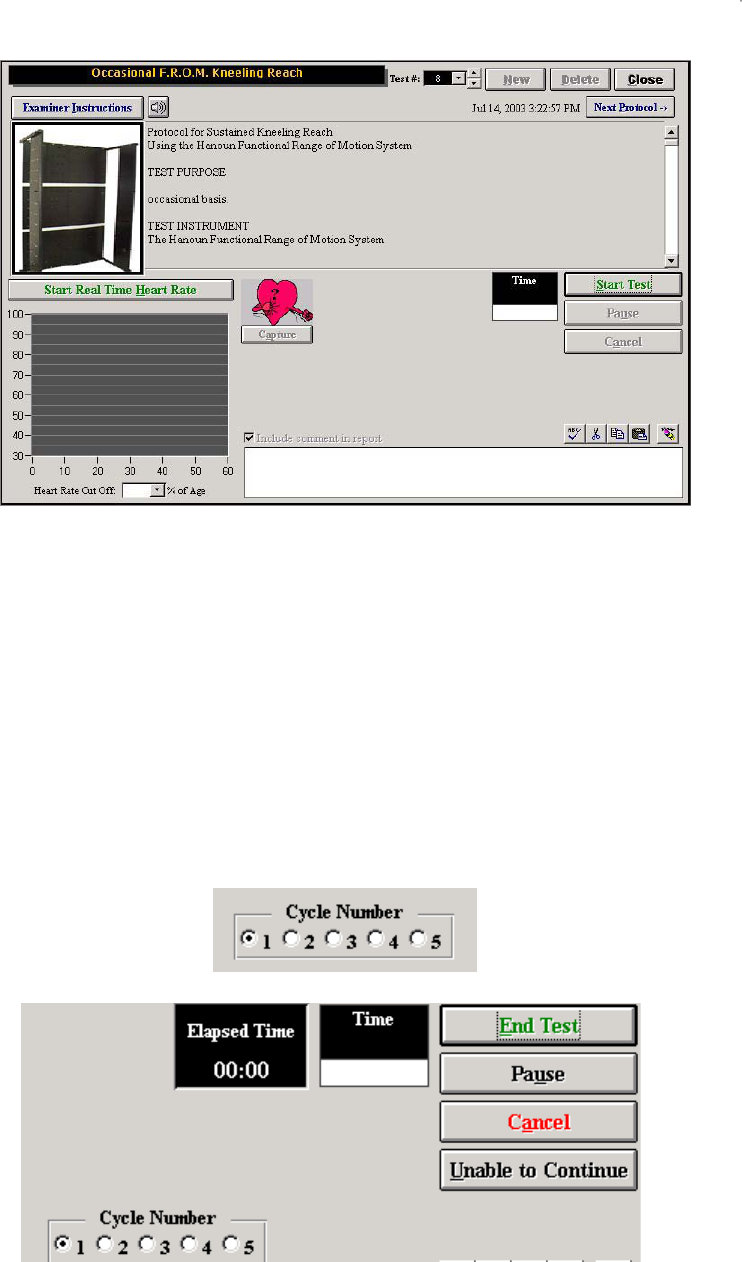
276
The client should be instructed in the proper technique prior to starting the test. The instructions need to
emphasize that the client is required to work as quickly as possible. It is recommended that two rows of
the protocol be completed, prior to starting the actual test, to make sure that the instructions were
understood. Click Examiner Instructions to switch to Patient Instructions. Click on the speaker button to
have the instructions read aloud by the computer.
Click Start Test to start the test. Click Start Real Time Heart Rate to start recording the heart rate. Click
Capture to record the heart rate in the heart rate report. Click Close to return to the Work Sim menu
The FROM protocol, once started, will provide the evaluator with a counter to track the number of cycles
the client has completed. The counter can be activated by either clicking on the numbered radio button
(as shown below) or by right clicking the mouse anywhere on the page.
Click Pause if the client did not understand the instructions and
then Resume to continue with the test when ready.

277
The test will end once you indicate (using the counter) that the final cycle is complete, or if you click End
Test or Unable to Continue. If the client is unable to continue the time will still be displayed but an MTM
rating will not be calculated, as the task was not completed.

278
BTE Digital Radio Frequency Heart Rate Monitor
The BTE Digital Radio Frequency Heart Rate Monitor is fully integrated with the Data Acquisition Box.
The use of the Heart Rate Monitor provides the ability to monitor a client’s heart rate. Unlike other heart
rate monitors, the BTE Heart Rate Monitor allows for constant monitoring during the work simulation tests
while remaining fully integrated with the computer. The range of the BTE Heart Rate Monitor has been
tested to be accurate for up to 30-50 feet.
Radio frequency allows for non-interruption of signal, therefore:
Clothing does not interfere
Radio signal does not require line-of-sight
Movement in front of the receiver does not block the signal
This equipment contains an RF module, which has been previously tested and found to
comply with the limits for a Class B digital device, pursuant to Part 15 of the FCC Rules.
These limits are designed to provide reasonable protection against harmful interference in
a residential installation. This equipment generates, uses and can radiate radio
frequency energy and if not installed and used in accordance with the instructions, may
cause harmful interference to radio communications. However there is no guarantee that
interference will not occur in a particular installation. If this equipment does cause
harmful interference to radio or television reception, which can be determined by turning
the equipment off and on, the user is encouraged to try to correct the interference by one
or more of the following measures:
Reorient or relocate the receiving antenna.
Increase the separation between the equipment and receiver.
Connect the equipment to an outlet on a circuit different from that to which the receiver is
connected.
Consult the dealer or an experienced radio/TV technician for help.
This equipment has been certified to comply with the limits for a Class B computing
device, pursuant to FCC Rules. In order to maintain compliance with FCC regulations,
shielded cables must be used with this equipment. Operation with non-approved
equipment or unshielded cables is likely to result in interference to radio and TV
reception. The user is cautioned that changes and modifications made to the equipment
without the approval of manufacturer could void the users authority to operate this
equipment.
ATTENTION
The Hanoun Digital Radio Frequency Heart Rate Monitor is a fitness-monitoring device
solely intended to monitor a client’s heart rate during physical testing. It is not a medical
device and should not be used in any way to diagnose a client’s health or to prescribe
treatment.
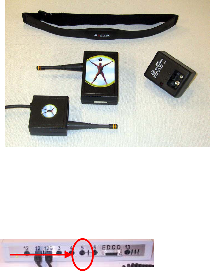
279
Components
BTE Digital Radio Frequency Transmitter
BTE Digital Radio Frequency Receiver
Polar Belt and Two Straps
Two extra 9 Volt batteries and a battery charger
Connecting the Heart Rate Receiver to the Data Acquisition Box
The BTE Heart Rate Monitor is designed to be readily attached to the Data Acquisition Box. Please
follow the instructions below:
Step 1: Attach the cable of the Receiver to Port 12.
Step 2: Place the Receiver in the Heart Rate Monitor holder on the BTE Computer Station.
Placement for the BTE Digital Radio Frequency Heart Rate Monitor
Step 1: Place the black strap underneath your client’s chest and directly against their skin. See diagram
as depicted below.
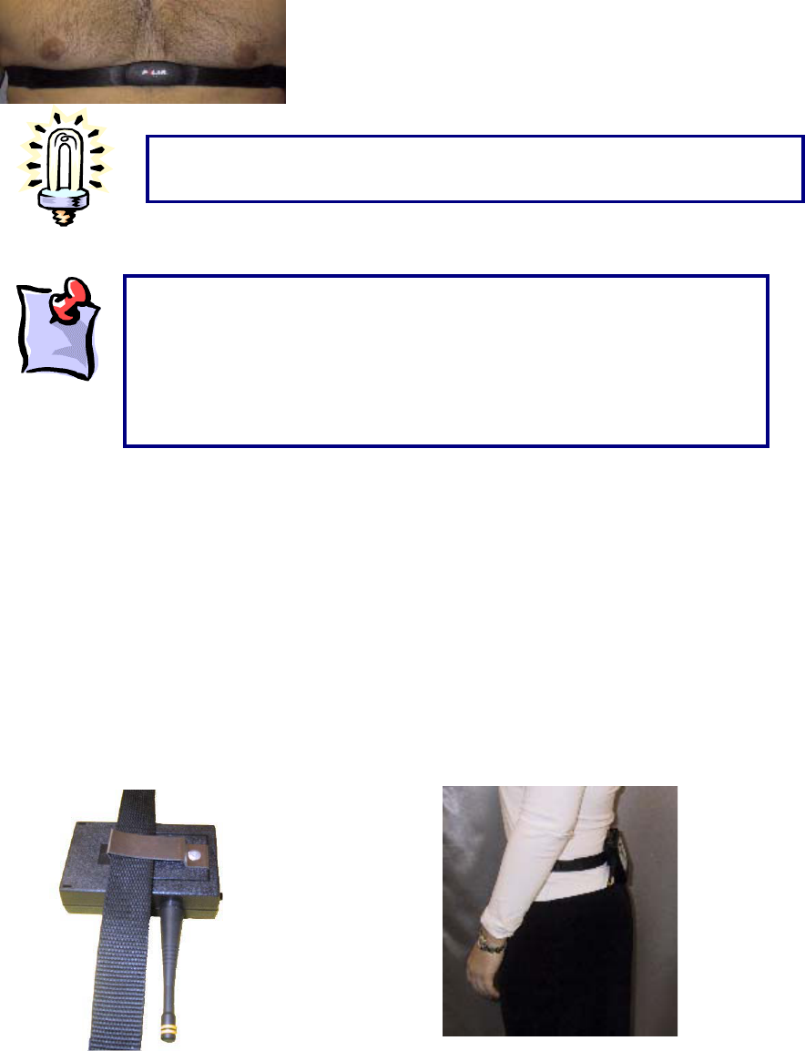
280
Many physiological characteristics also play a role in obtaining a heart rate and can differ from individual
to individual; for example, obesity, skin conductivity and body hair composition.
Body Positioning:
Back of the Client:
Place the transmitter on the back of the client, at beltline level. This is the optimal position, as it prevents
the transmitter getting in the client’s way during the testing procedures. First, attach the transmitter to
the belt strap that is supplied with the system. Next, place the strap around the client’s waist so that the
transmitter is positioned on their lower back.
For optimal signal, the use of electrode conductor gel or water on the heart
rate monitor chest strap is recommended.
For alternative placements, please see the troubleshooting section of
this manual. Please note that the Hanoun Heart Rate Monitor does
not operate like a Polar Heart Rate Monitor. The transmitter does
not store the values, so the readings are more accurate and updated
constantly. As a result, if the heart rate is fluctuating too much, the
heart rate monitor may not be able to pick up a constant value and a
“
?
”
will appear The heart rate must be steady in order for the device
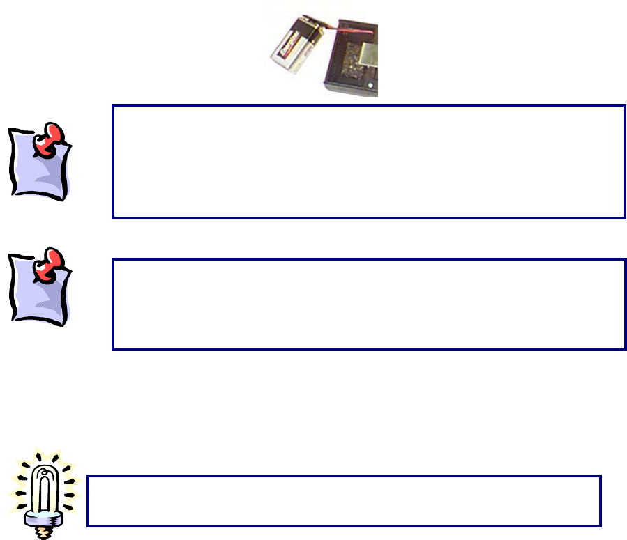
281
Operation of Monitor
When attaching the battery to your transmitter and depressing the on/off switch, the red light on the front
surface of the transmitter should light up indicating that the battery is good.
On/Off Switch
Located on the top of the Transmitter is the on/off switch. Prior to monitoring the client’s heart rate,
depress the switch to the ‘on’ position. The light will flash in time with the client’s heart rate.
Please note that if either of the two wires which run from the battery to the
Heart Rate Transmitter break, you will be responsible for their repair, as this is
not covered by the warranty. If it is hard to detach the battery, use a flat object
(such as a dull knife) to act like a wedge between the metal battery terminal
and the lar
g
e metal batter
y
connector.
When finished with the device, turn the on/off switch to the off position in orde
r
to preserve the life of the battery.
The rechargeable batteries need to be charged for a minimum of 12 hours
before use. The batteries are not charged when you first receive your system.
After charging them they will be good for up to 4 hours of testing in the Heart
Rate Monitor. If you are having difficulties capturing the client’s heart rate, try to
use a regular 9-volt battery. It is recommended you replace your rechargeable
batteries every year.
282
Heart Rate Receiver Testing
The Receiving unit performs a self-diagnostic on a continuous basis, indicated by the red light on the
back of the unit.
1 When the unit is attached to the Data Acquisition Box the red light will be illuminated to indicate
that it is receiving power.
283
Recommended Care and Maintenance Schedule
The following outlines the recommended maintenance schedule for your Hanoun System. A maintenance
log should be kept for the equipment.
It is recommended that if your computer is going to be used for other applications than ODES or if the
computer is connected to a network or the Internet, anti-virus software be installed.
After each Client
x Clean handles with an antibacterial wipe or rubbing alcohol (70% Alcohol) for sanitary reasons.
Daily
x Verify the equipment to be used to ensure it is measuring accurately. If verification fails, re-
calibrate the equipment.
x Make sure Handgrip is stored on the computer management stand with the end with the cord in
the top hook.
x Store all equipment so that the weight of the tool is not on the cord.
x Turn off the data acquisition box and computer at the end of the day.
x Back up your database (have a backup disk for each day of the week)
Weekly
x Calibrate and verify all tools.
x Back up your database (have a back up disk for each week of the month)
Monthly
x Clean the ER Column with a mild glass (15-20% Alcohol) or degreasing cleaner with a lint free
cloth.
x Re-lube the column with lightweight general lubrication oil using a lint free cloth.
x Check all wires to ensure they are secure and in good condition.
x Compact and Repair the ODES database. Refer to ODES section of manual.
x Clear hard drive of unnecessary files by going to Start ŇPrograms ŇAccessories ŇSystem Tools Ň
Disk Cleanup. Select the C Drive and select the files you wish to delete.
x Run the defragmenter program to ensure optimum computer performance. To do this go to Start
ŇPrograms ŇAccessories ŇSystem Tools Ň Disk Defragmenter.
Quarterly
x Remove all handles from the ER arms, FOCUS load cell and UTM and apply a white grease to
them.
x Check all the bolts on the EPIC crate and lifting shelves to make sure they are secure
Yearly
x Make sure the ER Platform is still level and make adjustments as appropriate.
284
Upon request circuit diagrams, parts lists, descriptions and other information required to repair parts may
be provided to a qualified technical person.
285
Transporting the Equipment
The following is required for shipping/transporting the BTE Evaluation and Rehabilitation System or
components to ensure its safe arrival at its final destination:
1) Package the computer monitor, CPU, printer, and speakers in the original packaging you received
them in. If you no longer have the original packaging material, it is recommended you take the equipment
to a postal center to have it packaged properly.
2) All the electrical tools (hand grip, pinch grip, algometer, inclinometer, goniometer, heart rate monitor,
data acquisition box, and FOCUS load cell) need to be packaged well in bubble wrap.
3) The Computer Management Stand must have the brakes on the wheels locked. If parts of the
equipment (i.e. the computer and electrical tools) are being placed on the computer management stand
during shipping, the stand must be bolted to a skid. Shrink-wrap can be used to prevent the load from
shifting during transportation.
4) The arms must be taken off the ER Platform and packaged in bubble wrap or the original packaging
they came in.
5) The handles for the FOCUS and UTM can be packaged in bubble wrap.
6) The Universal Task Master (UTM) needs to be packaged in bubble wrap. The white cable that
attaches the UTM to the data acquisition box.
7) The shelves must be lowered as far as they can so as to prevent the counter weight from moving
during shipping and the cable from breaking. Remove all the cables from the arms.
8) The post will need to be removed from the base of the platform. There are four screws that can be
removed using an Allen key. The post needs to be in a horizontal position for shipping.
9) The base of the platform can be shipped either flat or on its side.
It is recommended when packaging the base and the platform that a couple of strong people are available
due to the weight of the machine.

286
BTE MEDICAL INC. SOFTWARE - End User License Agreement
IMPORTANT—READ CAREFULLY: This BTE Medical Inc. End-User License Agreement (“EULA”)
is a legal agreement between you (either an individual or a single entity) and BTE Medical Inc. for
the ODES software product. The ODES software product includes computer software and may
include associated media, printed materials, and “online” or electronic documentation
(“SOFTWARE PRODUCT”). By installing, copying, or otherwise using the SOFTWARE PRODUCT,
you agree to be bound by the terms of this EULA. If you do not agree to the terms of this EULA, do
not install or use the SOFTWARE PRODUCT; you may, however, return it to your place of
purchase for a full refund.
SOFTWARE PRODUCT LICENSE
Copyright laws and international copyright treaties, as well as other intellectual property laws and treaties
protect the SOFTWARE PRODUCT. The SOFTWARE PRODUCT is licensed, not sold.
1 GRANT OF LICENSE. This EULA grants you the following rights:
x Applications Software. You may install and use one copy of the SOFTWARE
PRODUCT, or any prior version for the same operating system, on a single computer.
x Storage/Network Use. You may also store or install a copy of the SOFTWARE
PRODUCT on a storage device, such as a network server, used only to install or run the
SOFTWARE PRODUCT on your other computers over an internal network; however,
you must acquire and dedicate a license for each separate computer on which the
SOFTWARE PRODUCT is installed or run from the storage device. A license for the
SOFTWARE PRODUCT may not be shared or used concurrently on different
computers.
2 DESCRIPTION OF OTHER RIGHTS AND LIMITATIONS.
x Limitations on Reverse Engineering, Decompilation, and Disassembly. You may
not reverse engineer, decompile, or disassemble the SOFTWARE PRODUCT, except
and only to the extent that BTE Medical Inc. expressly permits such activity in writing
and where permitted by law.
x Separation of Components. The SOFTWARE PRODUCT is licensed as a single
product. Its component parts may not be separated for use on more than one computer.
x Rental. You may not rent, lease, or lend the SOFTWARE PRODUCT.
x Support Services. BTE Medical Inc. may provide you with support services related to
the SOFTWARE PRODUCT (“Support Services”). Use of Support Services is governed
by the BTE Medical Inc. policies and programs described in the user manual, in “online”
documentation, and/or in other BTE Medical Inc.-provided materials. Any supplemental
software code provided to you as part of the Support Services shall be considered part
of the SOFTWARE PRODUCT and subject to the terms and conditions of this EULA.
With respect to technical information you provide to BTE Medical Inc. as part of the
Support Services, BTE Medical Inc. may use such information for its business purposes,
including for product support and development. BTE Medical Inc. will not utilize such
technical information in a form that personally identifies you.

287
x Software Transfer. You may NOT transfer the SOFTWARE PRODUCT, either in whole
or in part, at any time. If you transfer the SOFTWARE PRODUCT, either in whole or in
part, you may be forced to pay for each additional copy or part thereof.
x Termination. Without prejudice to any other rights, BTE Medical Inc. may terminate this
EULA if you fail to comply with the terms and conditions of this EULA. In such event, you
must destroy all copies of the SOFTWARE PRODUCT and all of its component parts.
1 UPGRADES. If the SOFTWARE PRODUCT is labeled as an upgrade, you must be properly
licensed to use a product identified by BTE Medical Inc. as being eligible for the upgrade in
order to use the SOFTWARE PRODUCT. A SOFTWARE PRODUCT labeled as an upgrade
replaces and/or supplements the product that formed the basis for your eligibility for the
upgrade. You may use the resulting upgraded product only in accordance with the terms of
this EULA. If the SOFTWARE PRODUCT is an upgrade of a component of a package of
software programs that you licensed as a single product, the SOFTWARE PRODUCT may
be used and transferred only as part of that single product package and may not be
separated for use on more than one computer.
2 COPYRIGHT. All title and copyrights in and to the SOFTWARE PRODUCT (including but not
limited to any images, photographs, animations, video, audio, music, text, and “applets”
incorporated into the SOFTWARE PRODUCT), the accompanying printed materials, and any
copies of the SOFTWARE PRODUCT are owned by BTE Medical Inc. Copyright laws and
international treaty provisions protect the SOFTWARE PRODUCT. Therefore, you must treat
the SOFTWARE PRODUCT like any other copyrighted material except that you may install
the SOFTWARE PRODUCT on a single computer provided you keep the original solely for
backup or archival purposes. You may not copy the printed materials accompanying the
SOFTWARE PRODUCT.
3 DUAL-MEDIA SOFTWARE. You may receive the SOFTWARE PRODUCT in more than one
medium. Regardless of the type or size of medium you receive, you may use only one
medium that is appropriate for your single computer. You may not use or install the other
medium on another computer. You may not loan, rent, lease, or otherwise transfer the other
medium to another user, except as part of the permanent transfer (as provided above) of the
SOFTWARE PRODUCT.
MISCELLANEOUS
If you acquired this product in the United States, the laws of the State of Washington govern this EULA.
If you acquired this product in Canada, the laws of the Province of Ontario, Canada, govern this EULA.
Each of the parties hereto irrevocably attorns to the jurisdiction of the courts of the Province of Ontario
and further agrees to commence any litigation, which may arise hereunder in the courts located in the
Judicial District of York, Province of Ontario.
If this product was acquired outside the United States, then local law may apply.
Should you have any questions concerning this EULA, or if you desire to contact BTE Medical Inc. for any
reason, please contact the BTE Medical Inc. subsidiary serving your country, or write: BTE Medical Inc.
Sales Information Center/12 Ashwarren Road/Downsview, ON Canada M3J 1Z5.
LIMITED WARRANTY
LIMITED WARRANTY. BTE Medical Inc. warrants that (a) the SOFTWARE PRODUCT will perform
substantially in accordance with the accompanying written materials for a period of ninety (90) days from
the date of receipt, and (b) any Support Services provided by BTE Medical Inc. shall be substantially as
described in applicable written materials provided to you by BTE Medical Inc., and BTE Medical Inc.
support engineers will make commercially reasonable efforts to solve any problem issues. Some states
and jurisdictions do not allow limitations on duration of an implied warranty, so the above limitation may
not apply to you. To the extent allowed by applicable law, implied warranties on the SOFTWARE
PRODUCT, if any, are limited to ninety (90) days.

288
CUSTOMER REMEDIES. BTE Medical Inc.’s and its suppliers’ entire liability and your exclusive remedy
shall be, at BTE Medical Inc.’s option, either (a) return of the price paid, if any, or (b) repair or
replacement of the SOFTWARE PRODUCT that does not meet BTE Medical Inc.’s Limited Warranty and
which is returned to BTE Medical Inc. with a copy of your receipt. This Limited Warranty is void if failure of
the SOFTWARE PRODUCT has resulted from accident, abuse, or misapplication. Any replacement
SOFTWARE PRODUCT will be warranted for the remainder of the original warranty period or thirty (30)
days, whichever is longer. Outside the United States, neither these remedies nor any product support
services offered by BTE Medical Inc. are available without proof of purchase from an authorized
international source.
NO OTHER WARRANTIES. TO THE MAXIMUM EXTENT PERMITTED BY APPLICABLE LAW, BTE
MEDICAL INC. AND ITS SUPPLIERS DISCLAIM ALL OTHER WARRANTIES AND CONDITIONS,
EITHER EXPRESS OR IMPLIED, INCLUDING, BUT NOT LIMITED TO, IMPLIED WARRANTIES OF
MERCHANTABILITY, FITNESS FOR A PARTICULAR PURPOSE, TITLE, AND NON-INFRINGEMENT,
WITH REGARD TO THE SOFTWARE PRODUCT, AND THE PROVISION OF OR FAILURE TO
PROVIDE SUPPORT SERVICES. THIS LIMITED WARRANTY GIVES YOU SPECIFIC LEGAL RIGHTS.
YOU MAY HAVE OTHERS, WHICH VARY FROM STATE/JURISDICTION TO STATE/JURISDICTION.
LIMITATION OF LIABILITY. TO THE MAXIMUM EXTENT PERMITTED BY APPLICABLE LAW, IN NO
EVENT SHALL BTE MEDICAL INC. OR ITS SUPPLIERS BE LIABLE FOR ANY SPECIAL, INCIDENTAL,
INDIRECT, OR CONSEQUENTIAL DAMAGES WHATSOEVER (INCLUDING, WITHOUT LIMITATION,
DAMAGES FOR LOSS OF BUSINESS PROFITS, BUSINESS INTERRUPTION, LOSS OF BUSINESS
INFORMATION, OR ANY OTHER PECUNIARY LOSS) ARISING OUT OF THE USE OF OR INABILITY
TO USE THE SOFTWARE PRODUCT OR THE PROVISION OF OR FAILURE TO PROVIDE SUPPORT
SERVICES, EVEN IF BTE MEDICAL INC. HAS BEEN ADVISED OF THE POSSIBILITY OF SUCH
DAMAGES. IN ANY CASE, BTE MEDICAL INC.’S ENTIRE LIABILITY UNDER ANY PROVISION OF
THIS EULA SHALL BE LIMITED TO THE GREATER OF THE AMOUNT ACTUALLY PAID BY YOU FOR
THE SOFTWARE PRODUCT OR U.S.$5.00; PROVIDED, HOWEVER, IF YOU HAVE ENTERED INTO A
BTE MEDICAL INC. SUPPORT SERVICES AGREEMENT, BTE MEDICAL INC.’S ENTIRE LIABILITY
REGARDING SUPPORT SERVICES SHALL BE GOVERNED BY THE TERMS OF THAT AGREEMENT.
BECAUSE SOME STATES AND JURISDICTIONS DO NOT ALLOW THE EXCLUSION OR LIMITATION
OF LIABILITY, THE ABOVE LIMITATION MAY NOT APPLY.
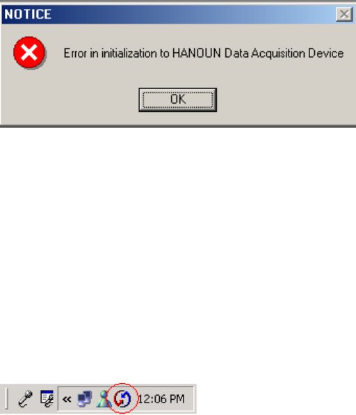
289
Trouble Shooting
Data Acquisition Box
“Error in initialization to BTE Data Acquisition Device”:
Click Auto in Administration | Environment Settings
Is the light on in the back of the box (red)? If so, turn box off for 30 seconds, then go to Administration |
Environment Settings, turn the box on and click Auto. If the red light still does not go off, unplug all the
tools, turn off the Data Acquisition Box and turn it back on. Click on Auto and add one tool at a time and
then click Auto. If a tool is plugged in a the above error is seen, this tool is shorting out the Data
Acquisition Box. Call BTE Customer Service for repair.
Is the light on in the front of the box? If not, make sure the box is on and connected properly. Try
alternative power outlet if light still does not go on.
Is the tool connected tightly into the port on the front of the Data Acquisition Box?
Is the serial cord connected tightly to COM port and to the DAC box?
Is there Palm Pilot or another Personal Device Assistant software loaded on the computer? A HotSync
icon (see below) in the bottom right hand corner of the screen is usually visible. Also check for the
software under Start ŇPrograms. If so, close the icon (it blocks the COM port) by right clicking your
mouse over it and select Exit.
Turn off the box, unplug all attachments from the front of the box, unplug the power supply from the box,
get out of ODES, shut down computer for 1 min. Turn the computer back on, get into ODES, plug the
power supply for the box in, turn the box on and click Auto in Administration | Environment Settings.
Check you printer setting under Start ŇSettings ŇPrinters to see which port they are printing to. If it is set
to COM1 it is blocking the serial port for the Data Acquisition Box. Change the port to LPT or USB
depending on where you plug the printer into the computer.
Check the status of your computer’s COM port by going to Start ŇSettings ŇControl Panel ŇSystem
ŇHardware ŇDevice Manager. Double click on Ports and then double click on the COM port. The status of
the COM port will be outlined in there. If it is not working properly following the troubleshooting tips there.
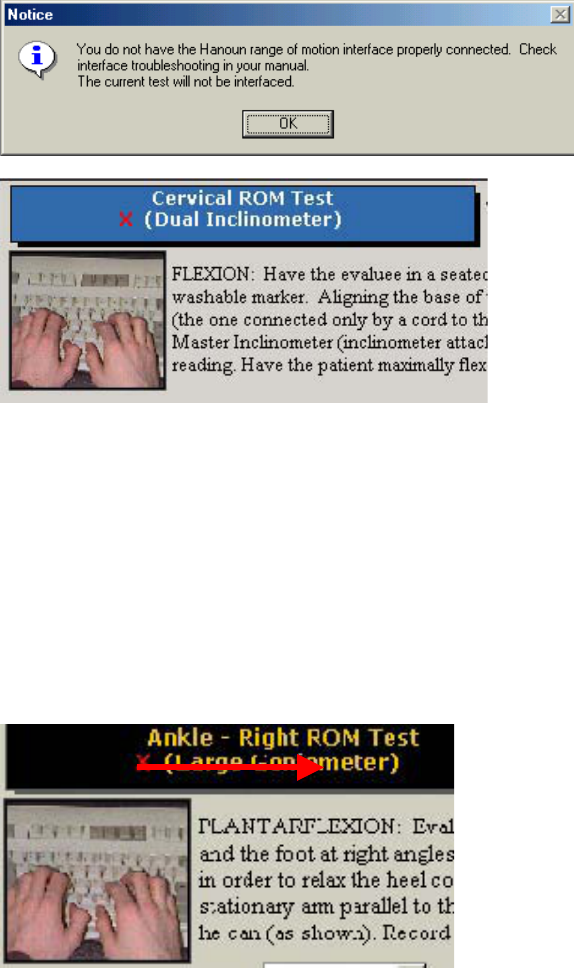
290
Inclinometer and Goniometer
If the interface system cannot be launched when using the BTE Dual Inclinometers, ensure that:
The cords are properly connected (into the Data Acquisition Box and between the Master and the
Remote)
The Range of Motion test that is selected in ODES is designed for use with either the Inclinometers or the
Goniometer, or is non-integrated. Check the top left corner of the test page to determine which tool the
software is looking for.
If you receive this message upon entering a range of motion testing page, you may not have the Data
Acquisition Box set up properly, or the device may not be attached correctly. Upon entering the testing
screen, you will notice a red ‘X’ beside the testing tool. This indicates a lack of communication between
the tool and the Data Acquisition Box.
Ensure that the tool is in the correct port.
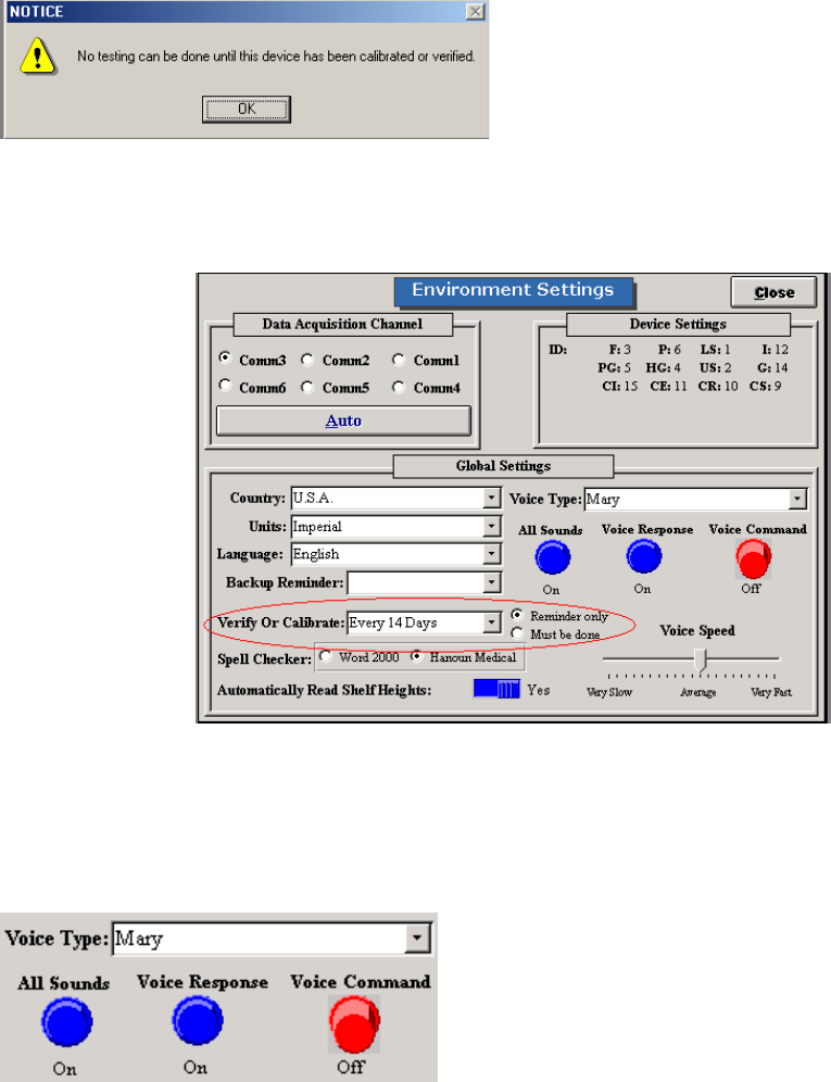
291
Hand Grip, Pinch Grip, Algometer, and FOCUS
“No Testing can be done until this device has been calibrated or verified”:
Has the tools been calibrated and verified? If not, calibrate and verify.
Is the Calibration/Verification reminder set to “must be done” or “reminder” in Administration |
Environment Settings? If on “must be done”, calibration must occur prior to performing a test. If set to
“reminder” tests can be performed without a new calibration.
The voice is not beginning the count down on your screen. You cannot perform any test (no prompts).
Go into Administration ŇEnvironment Settings. Make sure that Voice Response is on. Try to switch the
voice type to see if there are any problems with the speech software. If an error occurs you will need to
re-load the SAPI51 file located on the ODES CD under the Speech folder.
Cannot start the strength test that has been selected
Are your voices installed properly?
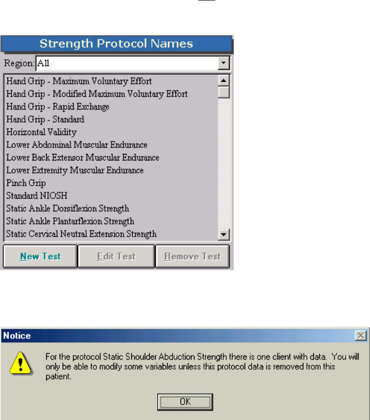
292
Do you have the correct tool selected? Only one strength tool can be associated with a protocol. You
have to create a duplicate test to utilize both the FOCUS and Algometer for a given protocol. To check if
the correct tool is selected, highlight the test from the Strength Protocol Screen.
Click Edit Test and see which tool is selected. NOTE: If you have previously done testing with this
protocol, you will receive a warning prior to entering the Edit Test screen. This will alert you that any
changes made to the protocol may affect data obtained previously for other clients.
Edit Test Screen: If you have performed this test with a tool already, the ‘Integrate Custom Test By’
section will be deactivated to prevent you from changing tools. This is why you have to create a duplicate
copy of the test to utilize a different testing device.
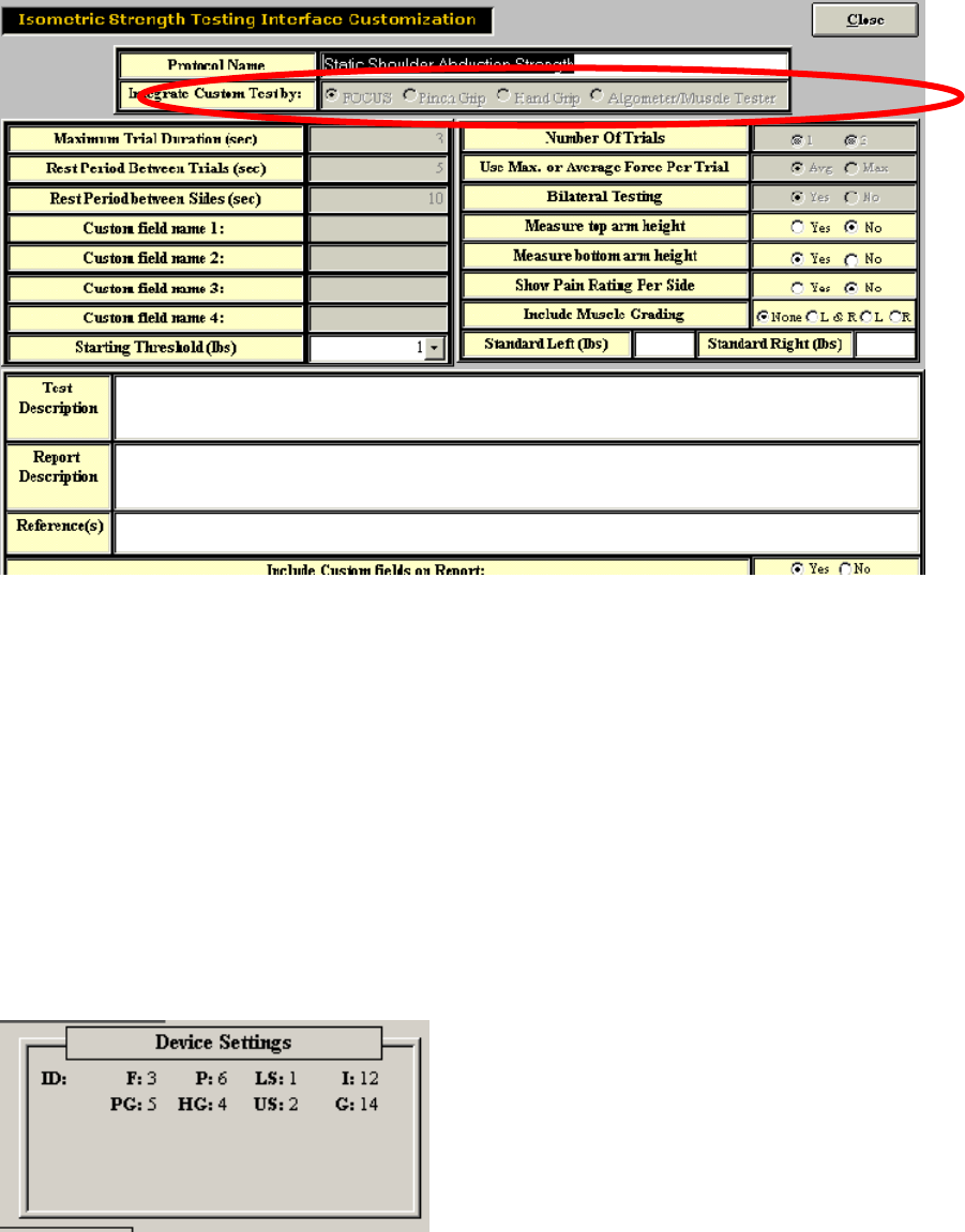
293
If the wrong tool is selected, create a new test using the same values (just a different name)
If the correct tool is selected, ensure that your DAC box is set up successfully.
If you still cannot perform the test, contact our customer service department at (800) 461-6888 X2.
Evaluator/CIRES Systems:
Ensure that your device settings are both set to PORT 6 in Administration _ Environmental Settings. This
will ensure that the Algometer will work in both the strength testing screens and in the superficial
tenderness testing screens.
To check device settings, go to Administration _ Environment Settings from the ODES main menu. The
device settings are listed in the upper right-hand corner of the screen.
The ‘F’ and ‘P’ values should both say ‘6’. If they don’t (as shown above), double click on the word
Device Settings. Device Settings should now be in red.
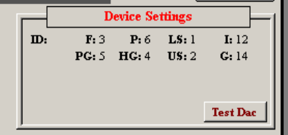
294
You are now able to modify the number located beside ‘F’ to ‘6’. To do this, click on the number 3 until it
reads 6. You have now set the Algometer to read in only port 6 for both strength and fibromyalgia tests.
Ensure that the Algometer is plugged into port 6.
Troubleshooting the Multiplanar Accessory Housing Joint
If you have problems inserting or removing the Multiplanar Accessory Housing Joint from one of the ER
arms, try the following:
Locate the small round silver pin on the right side of the upper or lower accessory arm (this pin is located
at the end of each arm). Try pulling the pin outward (further to the right), and then twist it slightly in any
direction. This will create space in the opening of the accessory arms’ end.
Locate the short black handle on the right side of the upper or lower accessory arm. This handle is
located at the end of each accessory arm. Turn the handle in a counterclockwise direction. This will
loosen the opening in the accessory arm.
These steps should loosen the openings in the ends of the accessory arms, and create space for the
insertion or removal of the Multiplanar Accessory Housing Joint.
If you have problems securing the Multiplanar Accessory Housing Joint to one of the ER arms, try the
following:
Locate the small round silver pin on the right side of the upper or lower accessory arm. This pin is
located at the end of each arm. Ensure that the pin is in the locked position (tucked into the far left). If it
is not, twist it slightly in any direction, until you hear a click. This will tighten the space in the opening of
the accessory arm’s end and secure the Multiplanar Accessory Housing Joint.
Troubleshooting: Accessory Attachment and Removal
If an accessory cannot be inserted into the Accessory Housing Joint, try the following:
Locate the handle on the top of the Accessory Housing Joint. This handle is on the right side of the
Multiplanar Accessory Housing Joint. Make sure that the handle is set to the unlocked position. In order
to be in the unlocked position, the handle must be given a ¼ turn in a counter-clockwise direction, and
then pulled outward. The handle can be maintained in the unlocked position by twisting it gently in either
direction.
Select the accessory to be attached. Be sure that the flattened end of the accessory is being inserted
into the housing mechanism facing to the right.
Grip the handle and twist it gently until a click is heard.
If an accessory cannot be removed from the accessory housing mechanism, try the following:
Locate the top handle of the Multiplanar Accessory Housing Joint.
Pull the handle and twist it gently in any direction.
295
Grip the accessory and pull it out of the Accessory Housing mechanism. You may need to gently rotate
the accessory and pull it upward in order to remove it.
Locate the short black handle on the right side of the upper or lower accessory arm. This handle is
located at the end of each accessory arm. Turn the handle in a clockwise direction. This will tighten the
opening in the accessory arm, and secure the Multiplanar Accessory Housing Joint.
These steps should tighten the openings at the ends of the accessory arms, and create a tighter fit
around the cylinder of the Multiplanar Accessory Housing Joint.
Troubleshooting: Multiplanar Accessory Housing Joint Rotation
If you cannot rotate the Multiplanar Accessory Housing Joint in the sagittal plane, try the following:
Ensure that you are using the correct handle. There are two handles on the Multiplanar Accessory
Housing Joint. The handle furthest from you when you are facing the ER, on your right-hand side, is the
one to adjust for sagittal rotation.
Ensure that you turn the handle counterclockwise approximately ¼ rotation.
Ensure that you pull the handle outward and hold it in this position while rotating the Multiplanar
Accessory Housing Joint.
If you cannot rotate the Multiplanar Accessory Housing Joint in the coronal plane try the following:
Ensure that the short black handle is properly unlocked by turning it counterclockwise approximately ¼
rotation.
Ensure that the small round pin is properly unlocked by pulling it outward (further to the right) and twisting
is gently in any direction.
Grip the Multiplanar Accessory Housing Joint and gently shake it to ensure that it is not stuck in a
particular position.
If the load cell does not appear to be accurate after you have calibrated it, check the following:
Was the Multiplanar Accessory Housing Joint properly connected to one of the ER accessory arms?
Did you calibrate the load cell with NO ATTACHMENTS on the Multiplanar Accessory Housing Joint?
Was the Multiplanar Accessory Housing Joint properly connected to the Data Acquisition Box?
Was the computer properly connected to the Data Acquisition Box?
Was the main power supply of the Data Acquisition Box properly connected?
Was the main power switch of the Data Acquisition Box turned to the ON position?
I feel the ER shelf height readings are not correct
Ensure the cable connections are correct and are tight at either end.
Check that it is plugged into the correct port.
Re-calibrate the shelves.
Check the DAC Box troubleshooting section.
If you are still having difficulty, re-route the cord from the DAC Box directly to the shelf (i.e. single cord
connection rather than a two-cord connection through the junction box at the base of either shelf ruler).
BE AWARE that the shelf height reading refers to the arm with the shelf / accessory attached and in the
up position. If horizontal then you must subtract 7.25 inches and if down you must subtract 14.5 inches
from the shelf height reading.
296
Universal Task Master
When I go into a UTM test, I get a message that says “Click OK to Calibrate” but I just calibrated
my UTM.
ODES and the UTM perform a self-calibration each time you use the UTM load cells. Since you calibrate
your UTM system without any accessories attached, the computer needs to first measure the accessory
prior to commencing a test. This will re-zero the load cell to include the accessory. Once you click OK,
you may proceed with the test.
One of the UTM load cell readings is not correct.
Ensure the cable connections are tight at the UTM center.
Ensure the cable connections are tight at the Data Acquisition Box.
Re-calibrate the load cell.
Check the Data Acquisition Box troubleshooting section.
The UTM handle rotation readings are not correct.
Ensure the cable connection is tight at the UTM center.
Ensure the cable connections are tight at the Data Acquisition Box.
Re-calibrate the handle rotation.
Check the Data Acquisition Box troubleshooting section.
The UTM force scale distance readings are not correct.
Ensure the cable connection is tight at the UTM center.
Ensure the cable connections are tight at the Data Acquisition Box.
Re-calibrate the force scale distances.
Check the Data Acquisition Box troubleshooting section.
Cannot select Start Test for one of the UTM tests.
Ensure the cable connection is tight at the UTM center.
Ensure the cable connections are tight at the Data Acquisition Box.
Re-calibrate the UTM.
Check the Data Acquisition Box troubleshooting section.
Exit the screen and re-enter the test.
Cannot see the Universal Task Master calibration icon in the Utilities menu.
The Universal Task Master option is not installed on your computer. Call the Customer Service
Department at BTE Medical.
Cannot select the Universal Task Master icon when I try to create a new strength test or work
simulation test.
The Universal Task Master option is not installed on your computer. Call the technical support
department at BTE Medical.
297
Heart Rate Monitor
Why am I not getting a reading with my Transmitter?
Is the red light on the back of the Transmitter flashing?
Is the receiver plugged into PORT 12 on the DAC box?
Under Help~About do you see HR=117? If not call BTE to unlock your Heart Rate Monitor.
Does the Transmitter battery need to be recharged?
Have you tested the Transmitter on a different subject?
Are you using a 9-volt battery? Have you tried a non-rechargeable one?
298
BTE Training Programs
BTE Medical Inc provides superior training to complement its leading technology. Introductory and advanced
courses are available.
ER Level One
This two day training course is for any individual who will be using the BTE functional testing technology. Training
will cover the use of each individual tool, basic principles of functional evaluations, how to use the protocol grid and
evaluations handbook, testing analysis, report writing and more.
ER Level Two
This one-day course covers advanced applications of the use of the BTE software and technology. The course is
developed ideally for those evaluators who have completed the ER Level One course, are familiar with the system,
and have completed a minimum of 20 functional tests. The course will include several cases studies to improve the
evaluator’s evaluation, analysis, and report writing skills.
E.P.I.C. Lifting Capacity
The ELC is the only peer reviewed and published lift capacity protocol, which measures all three domains of
function (biomechanical, physiological and psychophysiological). This one-day course is designed to prepare
healthcare professionals and technicians to provide standardized, reliable, valid and defensible evaluations with the
ELC evaluation. Information on course dates is provided to those who are interested.
Continuing Education Courses
BTE provides continuing education courses in post offer of employment testing, advanced marketing applications,
report writing, National Disability Evaluators Program and many others. Information regarding these courses is
posted on our website.
To obtain dates of upcoming courses and to register:
On-Line
www.BTETech.com
Call
(800) 331-8845 and ask for course registration