BTE Technologies WER-1 MCU Wireless User Manual 40040005 rev 000
BTE Technologies, Inc. MCU Wireless 40040005 rev 000
Contents
- 1. Installation Manual
- 2. Users Manual Part I
- 3. Users Manul Part II
Users Manul Part II
page
40
section 06
40040005 rev. 000
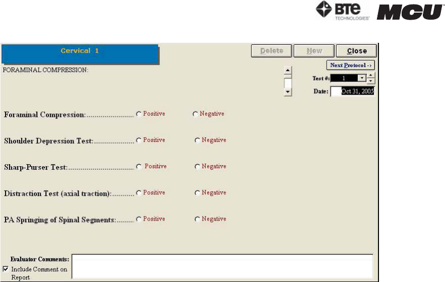
Depending on the test, every screen will look slightly different, but most will have the fol-
lowing features:
• Name of the test
• Delete icon to delete the selected test’s results
• New icon to begin a new set of test results
• Close icon to return to the protocol screen
• Next Protocol icon to move on to the next protocol
• Date of Test
• Instructions on how to perform the tests
• Comments field
Step 3. Follow the instructions, which are located at the top left of the screen, and in-
dicate whether the patient showed positive or negative results or if the location wasn’t
tested.
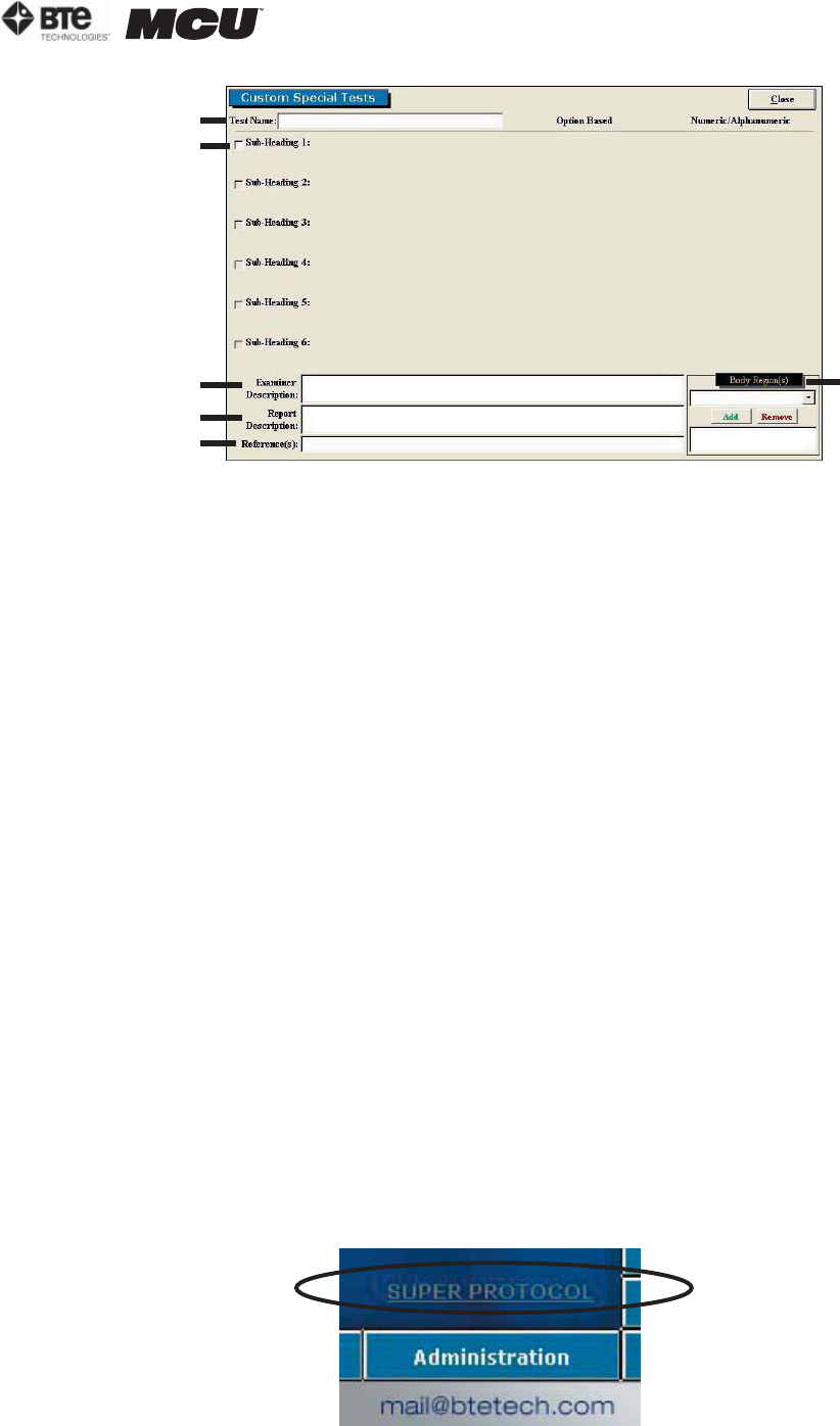
B. EDITING AND CREATING CLINICAL PROTOCOLS
Access the pre-programmed Clinical protocols by clicking the Clinical Tests icon on the
Home Screen.
This will bring you to the Clinical Protocols main page, where you can edit and create tests.
Edit a test by highlighting the test you would like to edit in the left box and clicking Edit
Test.
Create a new test by clicking on New Test.
If you are editing a test, a screen will appear with the current settings of the test you
selected. If you are creating a test, a screen will appear with the same headings as if you
were editing a test, but all of the text fields will blank (Figure 6-90).
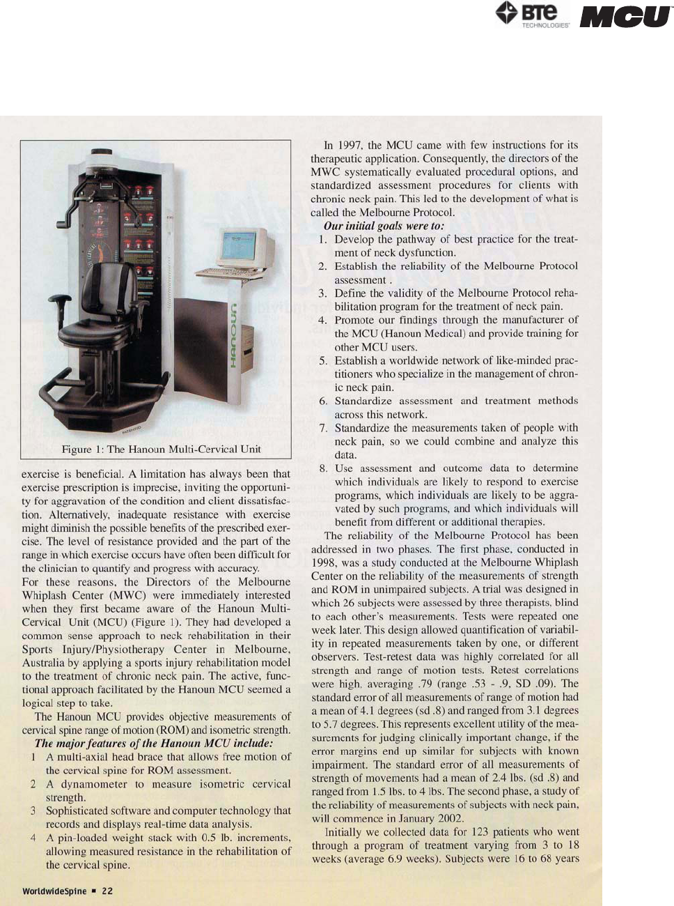
Figure 6-89. Clinical Protocol - Cervical 1
section 06
page
41
40040005 rev. 000
Since editing and creating protocols are very similar, an example of an edited test will be
given, but the same guidelines apply for creating a test.
The following can typically be edited or created on Clinical Protocols:
A. Test Name - Type in the name of the test
B. Sub-Heading - Type in the sub-headings to include in the test
C. Examiner Description - Type in any description the examiner will need to perform the
test - this field is especially useful for supplying instructions on how to perform the evalu-
ation
D. Report Description - Type in any description that should be included on the report
E. Reference Information - Include any reference information that needs to be added to
the report
F. Body Region - Select which body region is being evaluated
Once the screen has been closed, the protocol is saved under the assigned test name with
the new specifications.
VI. SUPER PROTOCOLS
Super Protocols can be created when you require a standardized protocol for testing (i.e. Post
Offer of Employment Testing). They can also be used if you want to decrease the amount of
time required to select specific tests for specific injuries.
The Melbourne Protocol has defined the optimal sequence of testing suitable for a patient suf-
fering Whiplash and Associated Disorders (WAD); this Super Protocol is covered in The Mel-
bourne Training Protocol. Refer to Section 10 for more information on this training program.
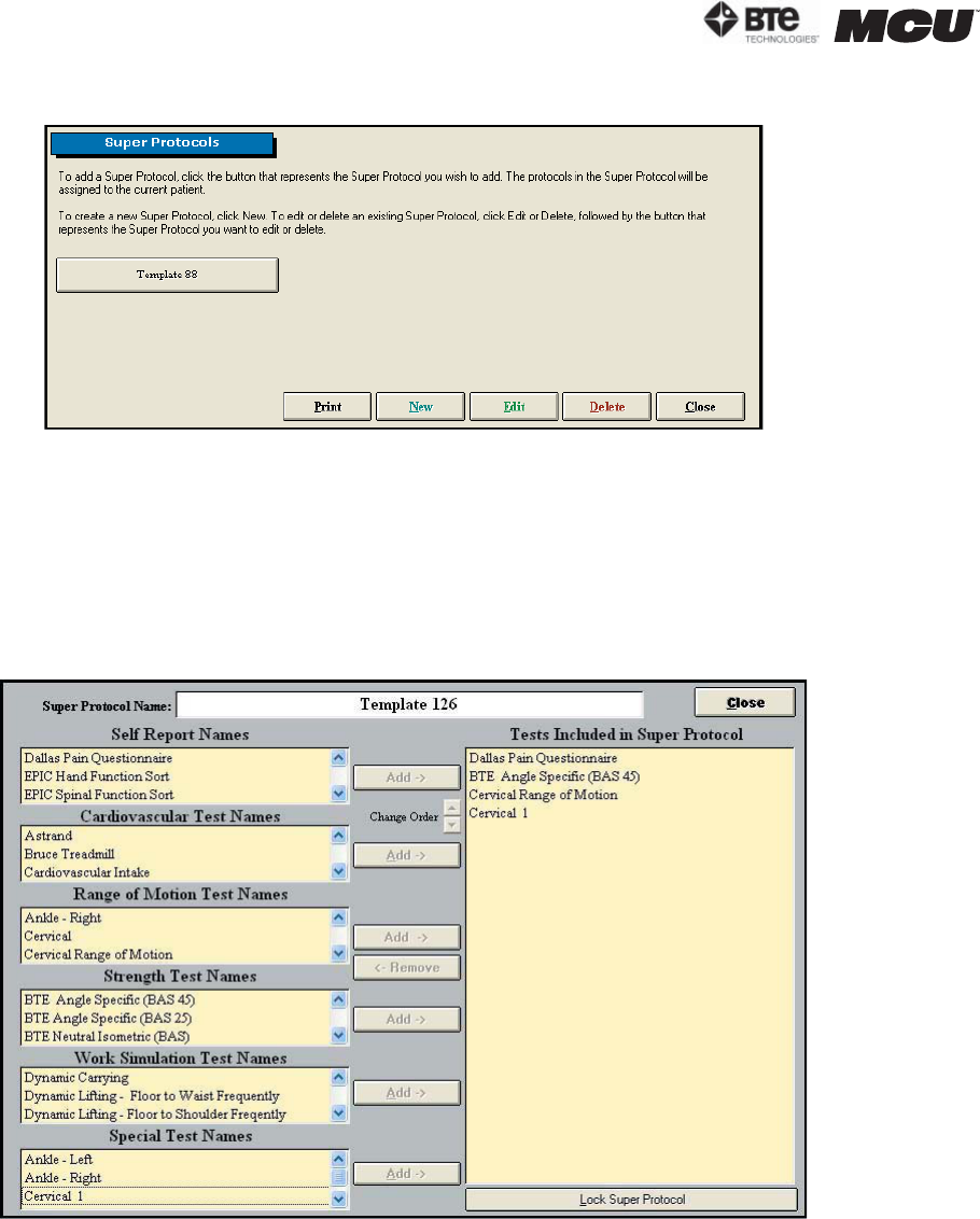
To create or access a super protocol, click on the Super Protocol link on the Home Screen
above the Administration icon (Figure 6-91).
Figure 6-91. Super Protocol Link
Figure 6-90. Custom Clinical Protocol
A
B
C
D
E
F
page
42
section 06
40040005 rev. 000
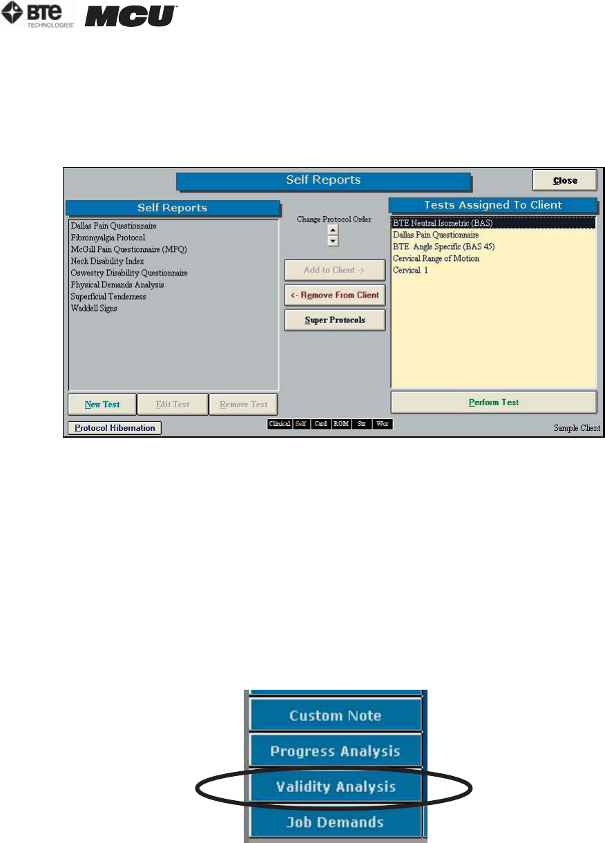
This will bring you to the main Super Protocols screen (Figure 6-92).
Step 1. Create a new protocol by clicking on New. A new icon will appear within the main Super
Protocols screen.
Step 2. To view the super protocol, first click on Edit; the Edit icon should change to Cancel
Edit. Next click on the super protocol you just created.
A screen will appear with boxes of test names on the left and a blank box on the right (Figure
6-93).
Step 3. Select the applicable tests from the lists on the left-hand side of the page and Add
them to the Super Protocol.
The order of testing can be changed by highlighting one of the included tests and using the
Change Order arrows to move it up or down within the list.
Step 4. Once you have added all the applicable tests and arranged them in the desired order,
finish the process by clicking Lock Super Protocol.
Step 5. You will be prompted to enter and confirm a password to lock the Super Protocol.
Step 6. To apply a Super Protocol, select a client then click Super Protocol from the Home
Figure 6-92. Super Protocol Main Screen
Figure 6-93. Create/Edit Super Protocol
section 06
page
43
40040005 rev. 000
Screen.
Step 7. Click the Super Protocol you wish to use.
A testing screen will appear with the tests for the super protocol already added to your client.
If other tests have already been added to the client, the super protocol tests will be listed be-
low them (Figure 6-94).
Edit a super protocol by clicking Edit in the main Super Protocol screen and selecting the su-
per protocol you wish to modify. You can then add and remove tests by highlighting a test and
clicking Add or Remove.
To delete any protocol, first click the Delete icon in the main Super Protocol screen; the De-
lete icon should change to Cancel Delete. Next click on the super protocol you wish to delete.
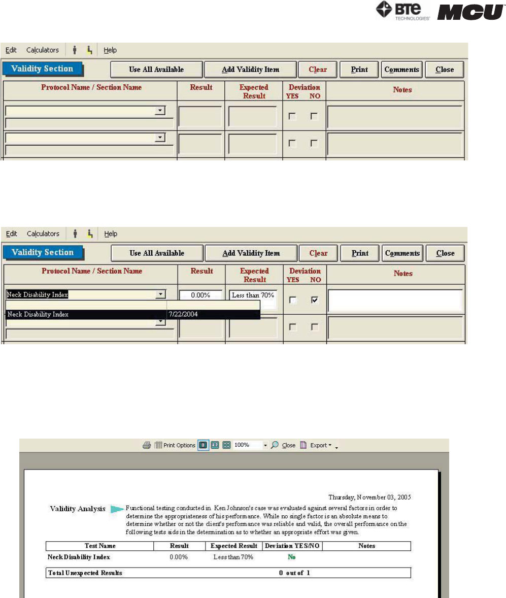
VII. VALIDITY ANALYSIS
The Validity Analysis allows you to evaluate the patient’s actual results versus the expected
results. This may be done for any or all of the tests completed by the patient.
Access the Validity Analysis by clicking on the Validity Analysis icon located on the Home
Screen. (Figure 6-95)
This will bring you to the main Validity Analysis screen (Figure 6-96).
Figure 6-94. Super Protocol Added to Client
Figure 6-95. Validity Analysis Icon
page
44
section 06
40040005 rev. 000
Step 1. Once the Validity Analysis screen is open, click on the arrow to the right of the first
drop-down menu and select the protocol you wish to evaluate. You may also click Use All Avail-
able if you wish to use all of the tests (Figure 6-97).
The Protocol or Section Name, Result, Expected Result, and Deviation fields will automatically
be populated.
Step 2. Add any necessary notes regarding the validity of the protocols.
Step 3. Click Print to preview the report (Figure 6-98).
You may also add protocols to the analysis by clicking Add Validity Name and typing in the pro-
tocol name, section name, and expected result.
Figure 6-96. Validity Analysis Main Screen
Figure 6-97. Select Protocol for Validity Analysis
Figure 6-98. Preview Validity Analysis Report

section 07
page
1
40040005 rev. 000
07 - REPORTS
Accessing the Reports 3
Types of Reports 6
Cervical Assessment 6
Custom Report 6
Custom Report (Non-Integrated) 6
FCA Progress Assessment (Non-Integrated) 7
FCA (Non-Integrated) 7
MCRP Assessment 7
MCRP Discharge Assessment 8
MCRP Progress Assessment 8
MCRP General Progress Assessment 8
MCRP Reassessment 9
MCRP Summary Report 10

page
2
section 07
40040005 rev. 000
section 07
page
3
40040005 rev. 000
REPORTS
I. ACCESSING THE REPORTS
ODES allows you to create a unique report that can include any information you deem neces-
sary, such as the raw data from a protocol, heart rate capture, or comments about the pa-
tient’s performance.
Access the Reports screen by clicking the Reports icon on the Home Screen.
Each report will be slightly different with respect to what may be included in it; the following
steps are a combination of what may be encountered for any one test. Therefore, follow only
those steps which apply to the report you wish to view.
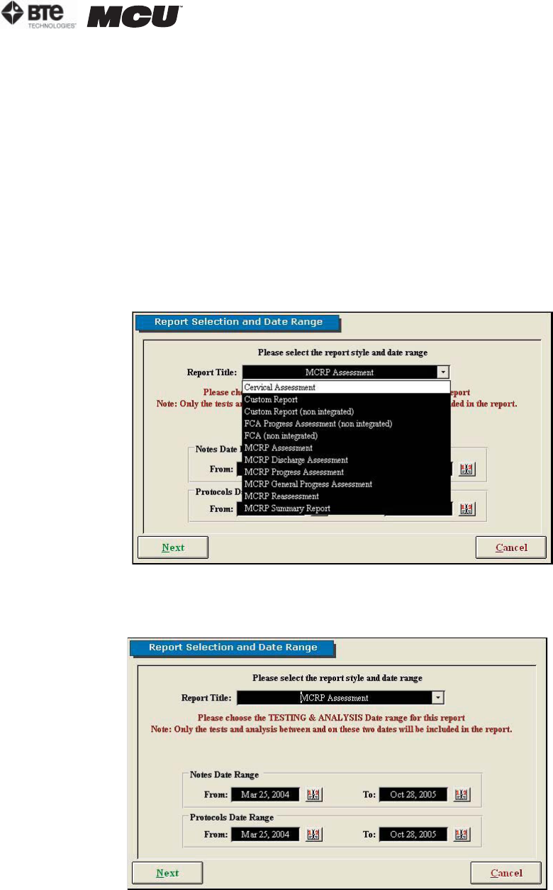
Step 1. Click on the arrow to the right of Report Title to access the drop-down menu and se-
lect the report you would like to view (Figure 7-1).
Step 2. Verify the appropriate start and end dates for the notes and for the protocol (Figure
7-2).
Figure 7-1. Report Title Selection
Figure 7-2. Report Selection & Date Range
page
4
section 07
40040005 rev. 000
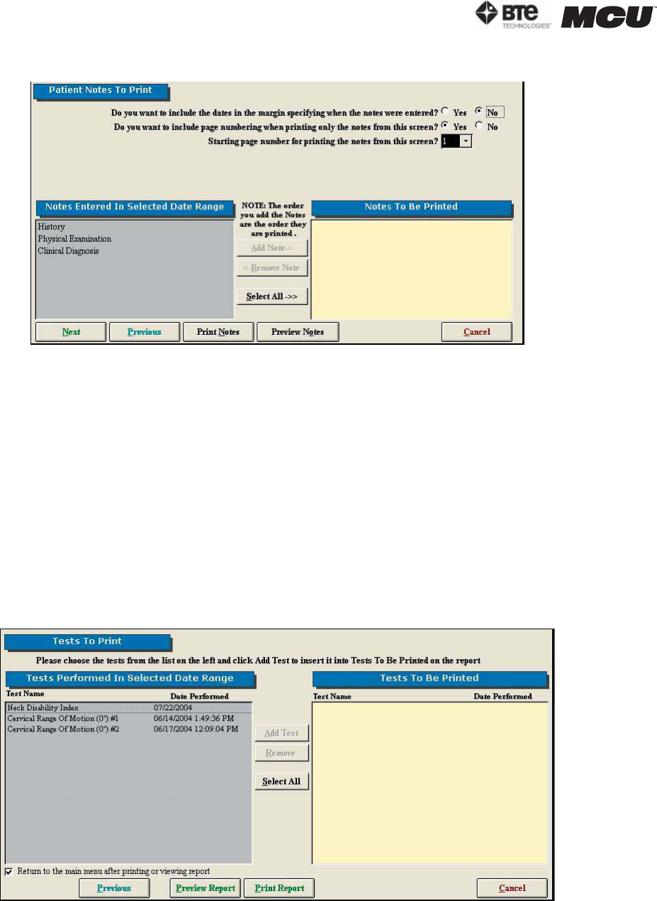
Step 3. Click Next. The Patient Notes to Print screen will appear (Figure 7-3).
Step 4. Select whether you would like to include the dates in the margin.
Step 5. Select whether you would like to include page numbering when printing the notes
from the Notes screen.
Step 6. Select whether you would like to start page numbering when printing the notes from
the Notes Screen.
Step 7. Choose which notes you would like to include in the report by highlighting the note
in the left box and clicking Add Note. If you wish to include all of the listed notes, click Select
All. If you would like to remove a note, highlight the note in the right box and click Remove
Note.
Step 8. Depending on which step you would like to do next, click Next, Print Notes, or Pre-
view Notes. Note that if you click Preview Notes, you will be able to print them from the Pre-
view Screen. If you click Next, the Tests to Print Screen will appear (Figure 7-4).
Step 9. Choose which tests you would like to include in the report by highlighting the test in
the left box and clicking Add Test. If you wish to include all of the listed tests, click Select All.
If you would like to remove a test, highlight the test in the right box and click Remove Test.
Figure 7-3. Patient Notes to Print
Figure 7-4. Tests to Print
section 07
page
5
40040005 rev. 000
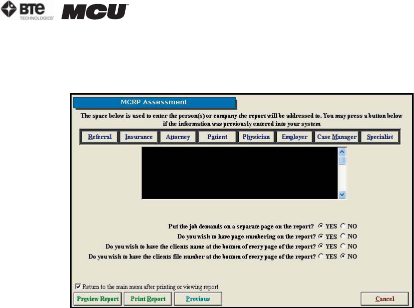
Step 10. Depending on which report you have selected to view and which step you would like
to do next, click Next, Print Notes, or Preview Notes. Note that if you click Preview Notes, you
will be able to print them from the Preview Screen. If you are able to click Next, the Report Op-
tions screen will appear (Figure 7-5).
Step 11. Choose whether you would like to address the report for a Referral, Insurance, At-
torney, Patient, Physician, Employer, Case Manager, or Specialist. If you select once of these
listed icons, the address needs to have been entered in the client information screen. If you
wish to address the report to a person or company other than the ones listed, or an address
hasn’t been entered in the client information screen, you may manually enter the address in
the text field.
Step 12. Select whether you would like to include the following in the report (note that these
may not be available for every report):
•Injury Location Diagram
•Injury Location Chart
•Evaluator Comments
•Job Demands on a separate page
•Page numbering
•Client’s name at the bottom of every page
•Client’s file number at the bottom of every page
Step 13. Type in a title name for this report and click Store. Note that this option may not ap-
pear for every type of report.
Step 14. Check the box if you would like to return to the Home Screen after previewing or
printing the report.
Step 15. Depending on which step you would like to do next, click Preview Report or Print Re-
port. Note that if you click Preview Report, you will be able to print it from the Preview screen.
If you choose Preview Report, the Report Preview screen will appear (Figure 7-6).
Figure 7-5. Report Options
page
6
section 07
40040005 rev. 000
II. TYPES OF REPORTS
Depending on which report you elect to view, each will look somewhat different. The following
is a list that includes each report type all the options that may be incorporated into it.
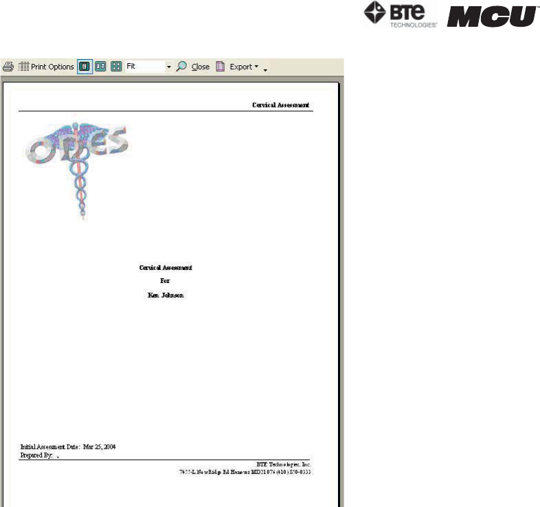
A. CERVICAL ASSESSMENT
This report allows you to:
•Select date range of data
•Add and remove client notes from the report
•Alter page numbers
•Enter dates in the margins beside client notes
•Select all or only specific tests to include on the report
•Print or preview the report
B. CUSTOM REPORT
This report allows you to:
•Select date range of data
•Alter pages numbers
•Add and remove client notes from the report
•Address the report to the following: Referral, Insurance Company, Attorney, Client, Physi-
cian, Employer, Case Manager
•Include injury diagram and/or chart on the report
Figure 7-6. Preview Report

section 07
page
7
40040005 rev. 000
•Put the job demand on a separate page
•Add or remove page numbers from the report
•Include clients name at the bottom of each page of the report
•Print or preview the report
•Create a custom title for the report
C. CUSTOM REPORT (NON-INTEGRATED)
This report is designed to include only Non-Integrated tests that have been performed.
This report allows you to:
•Select date range of data
•Alter pages numbers
•Add and remove client notes from the report
•Add specific non-integrated tests to your report
•Address the report to the following: Referral, Insurance Company, Attorney, Client, Physi-
cian, Employer, Case Manager
•Include injury diagram and/or chart on the report
•Put the job demand on a separate page
•Add or remove page numbers from the report
•Include clients name at the bottom of each page of the report
•Print or preview the report
•Create a custom title for the report
D. FCA PROGRESS ASSESSMENT (NON-INTEGRATED)
This report is designed to include only Non-Integrated tests that have been performed. It is
specifically used to track the progress of multiple assessments.
This report allows you to:
•Select date range of data
•Alter pages numbers
•Add and remove client notes from the report
•Add specific non-integrated tests to your report
•Address the report to the following: Referral, Insurance Company, Attorney, Client, Physi-
cian, Employer, Case Manager
•Include injury diagram and/or chart on the report
•Put the job demand on a separate page
•Add or remove page numbers from the report
•Include clients name at the bottom of each page of the report
•Print or preview the report
E. FCA (NON-INTEGRATED)
This report allows you to:
•Select date range of data
•Alter pages numbers
•Add and remove client notes from the report
•Add specific non-integrated tests to your report

page
8
section 07
40040005 rev. 000
F. MCRP ASSESSMENT
This report allows you to:
•Select date range of data
•Alter pages numbers
•Add and remove client notes from the report
•Address the report to the following: Referral, Insurance Company, Attorney, Client, Physi-
cian, Employer, Case Manager
•Include injury diagram and/or chart on the report
•Put the job demand on a separate page
•Add or remove page numbers from the report
•Include clients name at the bottom of each page of the report
•Print or preview the report
G. MCRP DISCHARGE ASSESSMENT
This report allows you to:
•Select date range of data
•Alter pages numbers
•Add and remove client notes from the report
•Address the report to the following: Referral, Insurance Company, Attorney, Client, Physi-
cian, Employer, Case Manager
•Include injury diagram and/or chart on the report
•Put the job demand on a separate page
•Add or remove page numbers from the report
•Include clients name at the bottom of each page of the report
•Print or preview the report
H. MCRP PROGRESS ASSESSMENT
This report allows you to:
•Select date range of data
•Put the job demand on a separate page
•Add or remove page numbers from the report
•Include clients name at the bottom of each page of the report
•Print or preview the report
I. MCRP GENERAL PROGRESS ASSESSMENT
This report allows you to:
•Select date range of data
•Alter pages numbers
•Add and remove client notes from the report
•Add specific tests to your report
•Address the report to the following: Referral, Insurance Company, Attorney, Client, Physi-
cian, Employer, Case Manager
•Include injury diagram and/or chart on the report
•Put the job demand on a separate page

section 07
page
9
40040005 rev. 000
•Add or remove page numbers from the report
•Include clients name at the bottom of each page of the report
•Print or preview the report
•Create a custom title for the report
J. MCRP REASSESSMENT
This report allows you to:
•Select date range of data
•Alter pages numbers
•Add and remove client notes from the report
•Add specific tests to your report
•Address the report to the following: Referral, Insurance Company, Attorney, Client, Physi-
cian, Employer, Case Manager
•Include injury diagram and/or chart on the report
•Put the job demand on a separate page
•Add or remove page numbers from the report
•Include clients name at the bottom of each page of the report
•Print or preview the report
K. MCRP SUMMARY REPORT
This report allows you to:
•Select date range of data
•Print preview all raw data obtained for a specific client

page
10
section 07
40040005 rev. 000

section 08
page
1
40040005 rev. 000
08 - CERVICAL CONDITIONING
Accessing Cervical Conditioning 3
Selecting Exercises 5
Blackout Feature 5
Target Feature 5
Tracking Dates 6
Supervising Practitioner 6
Weight Stack Selection 7
Seat Values 7
Minimum Values 8
Time 8
Starting % 8
Default 9
Accuracy Value 9
Notes 9

page
2
section 08
40040005 rev. 000
section 08
page
3
40040005 rev. 000
CERVICAL CONDITIONING
Recently, the exercise program portion of the ODES software has been reintroduced. Included
in this feature is a protocol for cervical conditioning. This function was created specifically for
Multi-Cervical™ Units and allows evaluators to customize cervical exercise programs for their
clients. Results are directly integrated into the software, making this feature extremely user
friendly, functional, and efficient.
The Rehabilitation Program on the MCU for patients suffering cervical conditions is covered
extensively during the training program on The Melbourne Protocol. This training program in-
cludes basic to advanced set-up to accommodate various patients groups including:
• Whiplash and Associated Disorders (WAD)
• Acute and Chronic Cervical Injury Management
• Specific Cervical Pathologies
• Hypertrophy Training for the Athlete
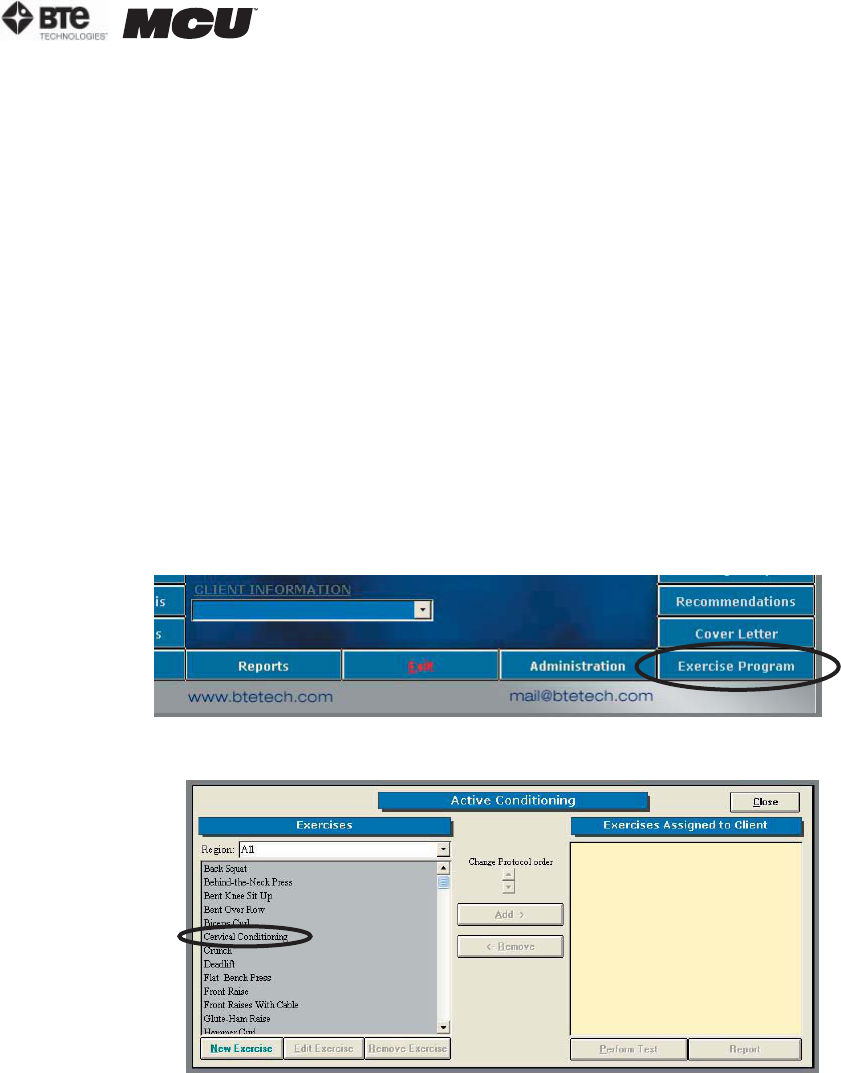
I. ACCESSING CERVICAL CONDITIONING
The cervical conditioning protocol can be located within the Exercise Program Menu. To locate
it, click on the Exercise Program Button located on the main screen of your ODES software
(Figure 8-1).
This will bring you to the Active Conditioning Protocol Screen (Figure 8-2):
In order to use the cervical conditioning feature, you may perform either of the following steps:
1. Highlight Cervical Conditioning on the left hand side and click the Add button.
2. Double click on Cervical Conditioning to add this protocol to the Exercises Assigned to
Client list.
Cervical Conditioning will now appear on the right hand side of your screen under Exercises As-
signed to Client (Figure 8-3).
Figure 8-1. Exercise Program Icon
Figure 8-2. Active Conditioning Protocols
page
4
section 08
40040005 rev. 000
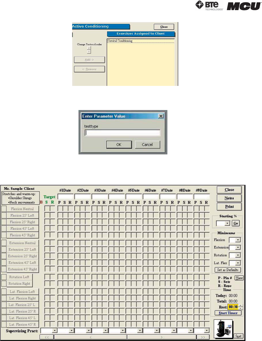
When entering the program for the first time, two warnings will appear; one is shown below
(Figure 8-4).
Simply click OK and you will be allowed into the cervical conditioning program.
You will now enter into the cervical conditioning screen (Figure 8-5).
Figure 8-4. Warning Screen
Figure 8-5. Cervical Conditioning Screen
Figure 8-3. Cervical Conditioning Selected
section 08
page
5
40040005 rev. 000
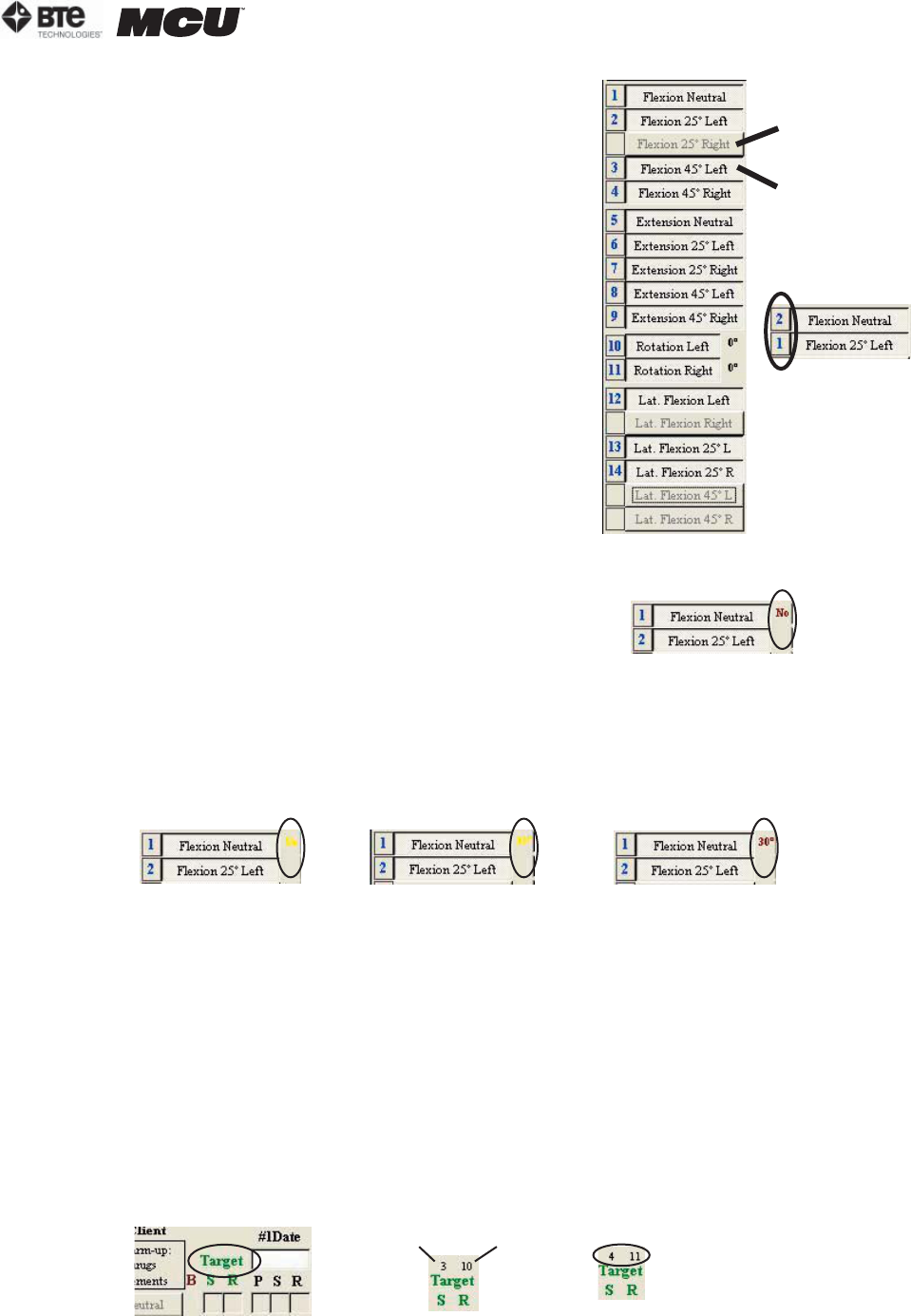
II. SELECTING EXERCISES
There are various options to choose from within the Cervical
Conditioning screen. On the left hand side of the screen, all
possible movements are listed. In order to select the exer-
cises for the client, simply click on the name of the move-
ment. A number will be assigned to the exercise, and the
name of the movement will turn black. If you wish to order
the exercises differently (e.g. place flexion in a neutral
position as exercise #2), simply double click on the number
beside the exercise, and all the numbers will change accord-
ingly (Figure 8-6).
III. BLACKOUT FEATURE
For certain movements, a blackout option is available. This is
important for client safety since it may be set to limit the range
of motion a client can perform safely. The blackout feature
automatically defaults to “no” – meaning no value is assigned
and the client can perform all exercises without any limitations
(Figure 8-7).
In order to set the blackout value, place your mouse over the word “no” – it should turn yellow.
Then double click your left mouse button in order to specify the maximum range of motion the
client should perform (Figure 8-8).
In the example above, the client should not exceed 30 degrees of neutral flexion. Therefore,
the pin on the halo should be placed in the 30 degree position to limit the movement.
IV. TARGET FEATURE
The target represents the number of sets and repetitions to be performed for each selected
exercise. The default for this is 3 sets of 10. It can, however, be changed. If you double click
on the word “target”, two numbers will appear above it. The number on the left represents the
number of sets that the program will default to, and the number on the right is the number of
repetitions. To change these default values, left click on the number you wish to change. Once
changed, these values will be the new defaults for ALL clients (Figure 8-9).
This exercise
has not been
chosen
Selected
exercise
Exercises
have been
reversed
Figure 8-6. Selecting Exercises
No blackout
has been
selected
Figure 8-7. No Blackout
No turns
yellow
Setting
blackout
value
Blackout has
been set to 30o
Figure 8-8. Setting Blackout Value
Sets Reps Double click
to change
sets or reps
Figure 8-9. Setting Target Value
page
6
section 08
40040005 rev. 000
V. TRACKING DATES
Multiple dates can be tracked within the software in order to perform continual conditioning
programs. The software also reminds you to do re-assessments to compliment the condition-
ing program. There is no limit or cap to how many conditioning programs a client may perform.
The date does not need to be manually inputted into the correct field. Instead, it will be im-
ported automatically after the rehab program has been initiated. You may also double click in
the blank field – a calendar will appear and you can select the correct date (Figure 8-10).
VI. SUPERVISING PRACTITIONER
To enter your name as a supervising practitioner, your name must be entered in case informa-
tion. If you have already entered yourself as a supervising practitioner, your name will appear
in the drop down menu. If not, go into case information; double click in the space besides su-
pervising practitioner (Figure 8-11).
Then, fill out the health practitioner screen (Figure 8-12).
Double click
for calendar
Figure 8-10. Setting the Date
Figure 8-11. Adding Supervising Practitioner
Figure 8-12. Health Practitioner Information
section 08
page
7
40040005 rev. 000
Your name will now appear in the drop down menu (Figure 8-13).
VII. WEIGHT STACK SELECTION
In order to make the cervical conditioning program specific to your
Multi-Cervical™ Unit, a feature was added to the software to allow you
to change the weight stack type. In order to alter this setting, you must
click on View in the bottom right hand corner of your screen (Figure 8-
14).
Once the View button is clicked, a table will appear that displays the pin
number and its corresponding weight (Figure 8-15).
VIII. SEAT VALUES
In the bottom right hand corner of your screen, you will find an icon that will al-
low you to make notes on the positioning of your seat (Figure 8-16).
To enter in information on your seat positioning, click on Seat.
This Seat Positioning screen allows you to comment on certain seat features which may or may
not be taken into account. For example, if you are utilizing lumbar support, place a check mark
in the box located beside “lumbar support”. You may now track these specifications for your
client and ensure that the same positioning is achieved for each conditioning session (Figure
8-17).
Figure 8-13. Supervising Practiioner Drop-Down Menu
Figure 8-14. Weight
Stack Setting
Figure 8-16.
Seat Icon
Figure 8-15. Weight
Stack Values
This space is
for additional
comments
Seat height
values (present
and previous)
are shown here
Store seat back
position here
Figure 8-17. Seat Settings
page
8
section 08
40040005 rev. 000
IX. MINIMUM VALUES
This feature in the cervical conditioning program allows the practitioner
to enter a minimum range that must be obtained in order for the motion to
register in the software (Figure 8-18).
For example, if the practitioner wishes to set a minimum value of 50 de-
grees for flexion, a minimum value of 50 should be selected. If this is the
case, the client must now perform at least 50 degrees of flexion before
the repetition will register in the software (Figure 8-19). Any minimum can
be selected, and if you wish, you can set these values as default values by
clicking on the Set as Defaults button.
X. TIME
The total time of the conditioning program (daily and cumulative) is shown in the lower right
hand corner of the testing screen. You may modify the client’s rest time with the correspond-
ing arrow (up increases the time allotted, down decreases the time allotted). Click start timer
when ready to begin (Figure 8-20).
XI. STARTING %
Before performing a cervical exercise program, a starting % should be selected.
This feature refers to the amount of weight being used (i.e. the PIN # you select
on your weight stack). After you select the correct weight stack type, you may
use this feature (Figure 8-21).
The data you receive from your cervical assessment of the client will
provide you with the maximum amount of weight that they can maneu-
ver in that motion. You will want to use a percentage of this weight for
the cervical conditioning program (i.e. 40% of their maximum capabili-
ties). In order to do this, select the correct percentage from the drop
down menu. When you click go, the software will automatically fill the
grid with the correct Pin # (i.e. the Pin that is associated with 40% of
the client’s maximum) (Figure 8-22).
XII. DEFAULT
The default button sets the values entered into the Starting %, Minimum
Values and Weight Stack fields as the default values for ALL patients (Fig-
ure 8-23).
XIII. ACCURACY VALUE
After double clicking on the word “Target”, a number “7” will appear in the very bottom left
hand corner of your screen (Figure 8-24).
Figure 8-18.
Minimum Settings
Figure 8-19.
Minimum Flexion
Setting
Left clicking with your
mouse in the yellow box
increases rest time by 1
hour.
Figure 8-20. Timer
Figure 8-22.
Setting Starting %
Figure 8-21.
Starting %
Figure 8-23.
Set as Default
section 08
page
9
40040005 rev. 000
This number relates to the number of degrees a client is allowed to be within to register a rep-
etition. In this case, the range is “7” degrees. Therefore, the repetition will not register until
the client is within 7 degrees from the initiation point of the motion. To change this value,
simply click on the number located in the bottom left hand corner.
IXV. NOTES
Notes can be added into the conditioning program. In order to do this, click on
Notes in the upper right hand corner (Figure 8-25).
The Notes screen will appear, which will allow you to enter in multiple notes on your client (Fig-
ure 8-26).
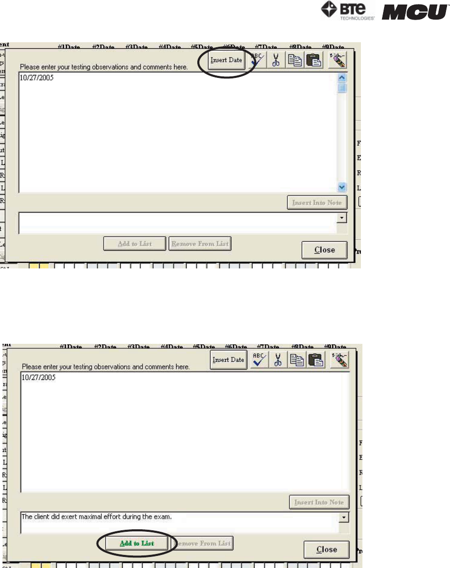
To enter in notes, place your cursor in the large upper white box. You may now type any infor-
mation that you wish to include. If you wish to include to date prior to entering your note, click
Insert Date (located on the tool bar). The date will now appear in the text box (Figure 8-27).
Figure 8-24. Accuracy Value
Figure 8-25.
Notes Icon
Figure 8-26. Notes Screen
page
10
section 08
40040005 rev. 000
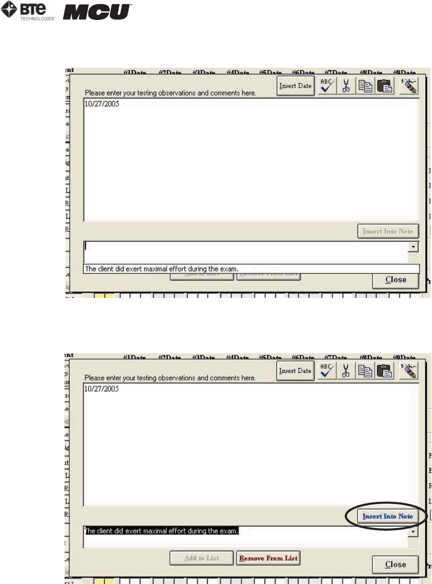
You may also enter information into a template format. This allows you to save popular phrases
so that you do not have to re-enter them time and time again. To do this, enter the information
you wish to save in the lower text box and then click Add to List, which is highlighted in green
(Figure 8-28).
Figure 8-27. Insert Date
Figure 8-28. Create a Common Note
section 08
page
11
40040005 rev. 000
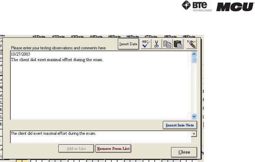
Your information will now appear in a list, which you can access by clicking on the drop down
icon (Figure 8-29).
To insert this information into your note, select the phrase you wish to include and click Insert
into Note, which is highlighted in blue (Figure 8-30).
Figure 8-29. Add Common Note to List
Figure 8-30. Select Common Note to Insert
page
12
section 08
40040005 rev. 000
Your information will now appear in the notes section (in the upper text box) (Figure 8-31).
Figure 8-31. Common Note Inserted into Main Notes Field

section 09
page
1
40040005 rev. 000
09 - RECOMMENDED MAINTENANCE
General Computer Maintenance 3
Do Not Install Additional Software 3
Shut Down the Computer Properly 3
Maintenance Schedule 3
General Product Maintenance 3
Do Not Disassemble Any Components of the MCU 3
Maintenance Schedule 3
After Each Client 4
Daily 4
Weekly 4
Monthly 4
Prevention of Interference between Wireless Components 4

page
2
section 09
40040005 rev. 000

section 09
page
3
40040005 rev. 000
RECOMMENDED CARE AND MAINTENANCE
I. GENERAL COMPUTER MAINTENANCE
ODES software runs in the Microsoft Windows XP environment; Windows XP Professional is an
extremely reliable and secure operating system, but extended use requires some degree of
system maintenance.
It is recommended that a log is kept for the maintenance of the computer equipment.
B. SHUT DOWN THE COMPUTER PROPERLY
To avoid possibly damaging the computer system, do not shut down the computer by simply
pressing the power button.
Step 1. When you are ready to shut down the MCU™, click Start at the bottom left corner
of the computer screen.
Step 2. Click Shut Down.
Step 3. Make sure Shut Down is highlighted in the drop-down menu and click OK.
C. MAINTENANCE SCHEDULE
1. DAILY
• Backup the database - you should have a backup disk for each day of the week
2. WEEKLY
• Backup the database - you should have a backup disk for each week of the month
3. MONTHLY
• Compact and repair the ODES database - see Section 2 for instructions
• Clear hard drive of any unnecessary files (go to Start| Programs | Accessories | Sys-
tem Tools | Disk Cleanup, select the C Drive and then the files you would like to de-
lete)
• Run the defragment program to ensure optimum computer performance (go to Start |
Programs | Accessories | System Tools | Disk Defragmenter)
II. GENERAL PRODUCT MAINTENANCE
The MCU™ station and tools are designed to be robust and used frequently, but extended use
requires some degree of maintenance.
It is recommended that a log is kept for the maintenance of the system.
A. DO NOT DISASSEMBLE ANY COMPONENTS OF THE MCU™
Do not attempt to disassemble any component of the MCU™ or its tools. The system is as-
sembled in such a way that components of it may break if disassembled incorrectly.
If one of the BTE Technologies products is not working properly, call customer service at
1-800-331-8845 so the problem may be properly diagnosed and repaired.
A. DO NOT INSTALL ADDITIONAL SOFTWARE
Do not install any additional software onto the controlling computer. The BTE Technologies
MCU™ system is in constant communication with the computer, so a “clean”, dedicated
computer system is crucial to the integrity of this communication system.

page
4
section 09
40040005 rev. 000
B. MAINTENANCE SCHEDULE
1. AFTER EACH CLIENT
• Clean the head braces and arm rests with an antibacterial wipe or rubbing alcohol
(70% alcohol). Make sure to not allow any liquid to enter the RJ45 jacks on the head
braces or the top of the column.
2. DAILY
• Verify any equipment that has been calibrated. If verification fails, then recalibrate
the tool
• Clean the halo with an antibacterial wipe or rubbing alcohol (70% alcohol)
• Clean the seat bottom and back with an antibacterial wipe or rubbing alcohol (70%
alcohol)
3. WEEKLY
• Calibrate and verify all tools
4. MONTHLY
• Check all the cables to ensure they are secure and in good working condition
III. PREVENTION OF INTERFERENCE BETWEEN WIRELESS COMPONENTS
Interference, which can result in an inability to acquire accurate data, may occur in the follow-
ing scenarios:
a. There are multiple wireless systems within 50 feet of each other that are on the same
wireless channel (e.g. 2 wireless MCUs in the same clinic on channel 16).
b. The antennas of any wireless components are within 3 feet of each other (e.g. the an-
tenna on the Hub is within 3 feet of the antenna on top of the MCU).
c. There is not a direct line of sight between the antennas of the wireless components. In
addition, any metal that is between the antennas will cause interference.
You may prevent interference by maintaining your system in the following manner:
a. Do not allow the Hub to fall on the floor; there are magnets inside the Hub that will aid
in securing it to the computer cart.
b. Regularly check the USB cable that is attached to the Hub and check the power cable
that is attached to the MCU.
c. Verify the antennas are in good working order and properly secured.
You may also prevent interference by using the following guidelines:
a. If there are multiple wireless systems within 50 feet of each, verify that each unit is on
a different wireless channel. Refer to Section 02-IV-C-4 (URFIO Configuration Applica-
tion) for how to determine on which channel a system is operating.
b. The recommended location for the Hub is on the second shelf of the computer cart. This
ensures the antenna of the Hub will always be at least 3 feet from the antenna on the
top of the MCU.
c. Verify there is a direct line of sight between the Hub antenna and the MCU antenna.

section 10
page
1
40040005 rev. 000
10 - THE MELBOURNE PROTOCOL
Introduction 3
Outcome Data Reliability Summary 4
Reliability Study Data 5
World Wide Spine Article 6
“Pain in the Neck” Article 11

page
2
section 10
40040005 rev. 000

section 10
page
3
40040005 rev. 000
THE MELBOURNE PROTOCOL
To compliment the BTE User Manual, Robert De Nardis, (Physiotherapist, Director of the Mel-
bourne Whiplash Centre and Panel Member for the International Whiplash Taskforce) has de-
signed a specific protocol (The Melbourne Protocol), which is gaining international recognition
and is being used in over 50 specialist whiplash facilities around the world. The Melbourne
Protocol details evaluation and treatment protocols based on evidence from ongoing research
into the treatment of Whiplash and Associated Disorders (WAD). Some of the topics covered in
training include:
- Assistance with branding your Center as a Neck Care Center of Excellence
- Whiplash Center Marketing Strategies (12 month Marketing Plan provided
- Whiplash Center Business Administration
- Reliability and Validity on the Multi-Cervical™ Unit
- Initial assessment protocols including Vertebro-Basilar Insufficiency (VBI) Testing and the
application of Functional Questionnaires
- Management of the Irritable Patient and Exclusion Criteria for The Multi-Cervical™ Unit
- Treatment Protocols including Contra-indications for Treatment and Key Prognostic Indica-
tors from current research
- Patient Positioning for Evaluation of Range of Motion and Isometric Strength on The
Multi-Cervical™ Unit
- Patient Positioning for Treatment on the Multi-Cervical™ Unit
- Advanced Treatment Ideas and Options for Whiplash and Associated Disorders Patients
- Current Whiplash and Associated Disorders Research Trends
- Collecting and Analyzing Data Collected on The Multi-Cervical™ Unit
- Research at The Melbourne Whiplash Centre
Contact BTE Technologies for more information on registering for this program:
U.S. & Canada: 800.331.8845
International: 410.850.0333
Fax: 410.850.5244
Internet: www.btetech.com/training_sched.htm

page
4
section 10
40040005 rev. 000
Greenwood, K.M. & De Nardis, R.J. (2000). Melbourne Whiplash Centre Outcome Data.
Preliminary Report. Melbourne Whiplash Centre (Manuscript in preparation).
Summary of Findings
Having established that the measures produced by The Melbourne Protocol on the BTE Multi-Cervical Unit
have an acceptable degree of reliability (Greenwood & De Nardis, 2000a), the focus of research attention should
now move to the issue of the validity of measurements and the efficacy of therapy using the unit. Validity refers
to the “appropriateness, meaningfulness, and usefulness of the specific inferences made from test scores”
(Standards for Educational and Psychological Testing, 1985, p.9).
Method
The data were obtained from 123 patients (66% female, average age 40.4 years, average chronicity of symptoms
98.0 months, average duration of treatment 6.9 weeks). Patients were assessed before and after the treatment
program on 8 variables: scores on Neck Disability Index, strength of isometric Flexion/Extension/Lateral
Flexion and range of motion of Flexion/Extension/Lateral Flexion/Rotation.
Paired t-tests were used to compare changes from pre- to post-program values.
Results
Pre-Program Post-Program t df p
Measure
Neck Disability Index 33.8 17.5 15.165 98 <.001
ROM (degrees)
Flexion 58.2 65.5 -8.041 116 <.001
Extension 48.7 55.3 -6.530 115 <.001
Lateral Flexion 38.8 48.0 -10.695 114 <.001
Rotation 63.5 73.4 -8.593 114 <.001
Isometric Strength (lbs)
Flexion 10.1 17.1 -15.808 116 <.001
Extension 14.5 25.0 -15.352 117 <.001
Lateral Flexion 10.9 18.6 -14.490 116 <.001
It can be seen that highly significant changes were found in all variables in the expected direction, most notably
for strength. It is clear from these results that treatments using the Melbourne Protocol with the BTE Multi-
Cervical Unit results in improvements in Neck Disability Index, strength and ROM in these patients as a group.
Six month follow-up data (thus far only available for 18 patients) indicates that there is no evidence of changes
in the values of NDI, strength and ROM from post-program to 6 month recording. Therefore, treatment gains
have persisted in this sample.

section 10
page
5
40040005 rev. 000
Greenwood, K.M. & De Nardis, R. (2000). An assessment of the reliability of
measurements made using the Melbourne Protocol and the BTE Multi-Cervical Unit.
Melbourne Whiplash Centre (Manuscript in preparation).
Summary of Findings
The reliability of a measurement refers to “the consistency, the reproducibility and the repeatability
of the instrument or measurement procedure” (Richman, Makrides & Prince, 1980).
The Reliability Trial
To assess the reliability of measures made using The Melbourne Protocol and the BTE Multi-Cervical
Unit, a trial was designed in which 26 individuals (who did not have ailments involving the neck)
were assessed by three therapists on two occasions each. The trial allowed assessment of inter-
observer and intra-observer reliability.
Results:
Inter-Tester Reliability
The consistency of a measurement technique when used by different clinicians over time.
xSystematic Difference between Therapists
Results indicate a good degree of agreement between therapists. All averages reported were
within 3.3 degrees for ROM measurements and 0.8 lbs for strength measurements.
xOrder of Testing Effects
There were no systematic differences between the first, second and third measurements. Results
indicate that there are no major “warm-up” or familiarisation of technique changes in value and
further indicate that the pre-measurement trials conducted in the protocol are sufficient to rule out
these effects.
xRelationship Between the Therapists’ Scores – Correlations
Correlation coefficients are high (.747 to .949 [approaching 1.0]) indicating good inter-observer
reliability.
xRelationship Between Therapists’ Scores – ICCs
Intra-Class correlation coefficients are high (.767 to .930 [approaching 1.0]) indicating good inter-
observer reliability.
xStandard Error of Measurement
SEM’s are low (1.56 to 4.10) indicating good inter-therapist reliability.
Intra-Tester Reliability
The consistency of a measurement technique when used by the same clinician over time.
xSystematic Changes Over Time
No systematic differences were identified in scores over time.
xRelationship Between the Therapists’ Scores – Test-Retest Correlations
The majority of the correlation coefficients are high (.667 to .895 [approaching 1.0]) indicating
good test-retest reliability. ROM extension scores were lower (.529 to .747) indicating some
attention is required for this particular measure.
xTest-Retest Reliability of Therapists’ Scores – ICCs
The majority of the ICC’s are high (.654 to .879 [approaching 1.0]) indicating good test-retest
reliability. Again ROM extension was lower (.531 to .742).
xStandard Error of Measurement
SEM’s are low (1.54 to 5.73) indicating good test-retest reliability.
xMinimum Detectable Change – Test-Retest
The same therapist over a one week period can reliably detect changes of around 10 degrees in
ROM and around 5lbs in strength.

page
6
section 10
40040005 rev. 000
section 10
page
7
40040005 rev. 000
page
8
section 10
40040005 rev. 000
section 10
page
9
40040005 rev. 000
page
10
section 10
40040005 rev. 000
section 10
page
11
40040005 rev. 000
page
12
section 10
40040005 rev. 000