BTE Technologies WER-1 MCU Wireless User Manual 40040005 rev 000
BTE Technologies, Inc. MCU Wireless 40040005 rev 000
UserManual.wiki
>
BTE Technologies
>
WER-1 User Manual
>
Users Manul Part II
Contents
1.
Installation Manual
2.
Users Manual Part I
3.
Users Manul Part II
Users Manul Part II
Navigation menu
Upload a User Manual
Namespaces
Wiki Guide
HTML
PDF
Info
Views
User Manual
Discussion / Help
Navigation
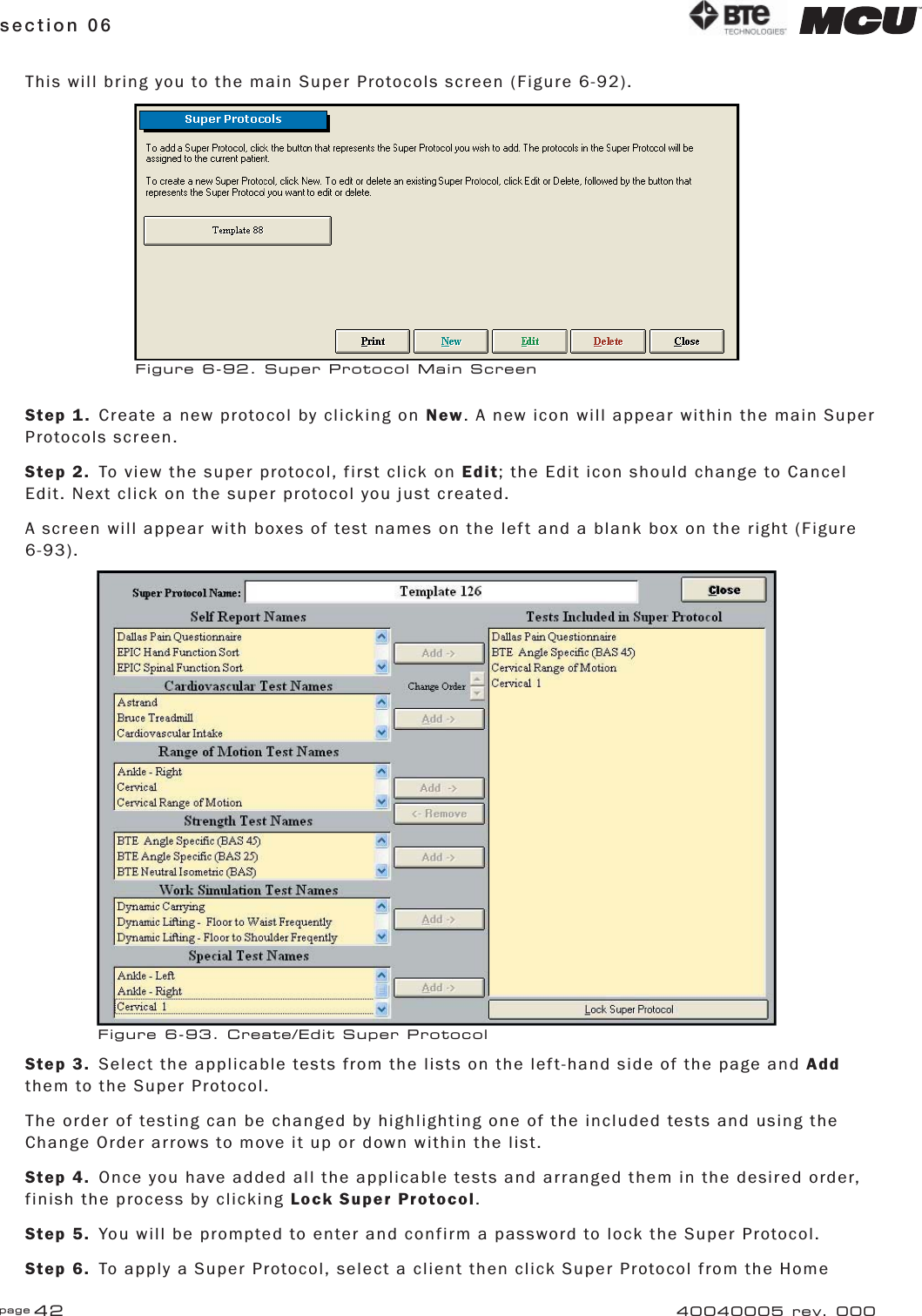
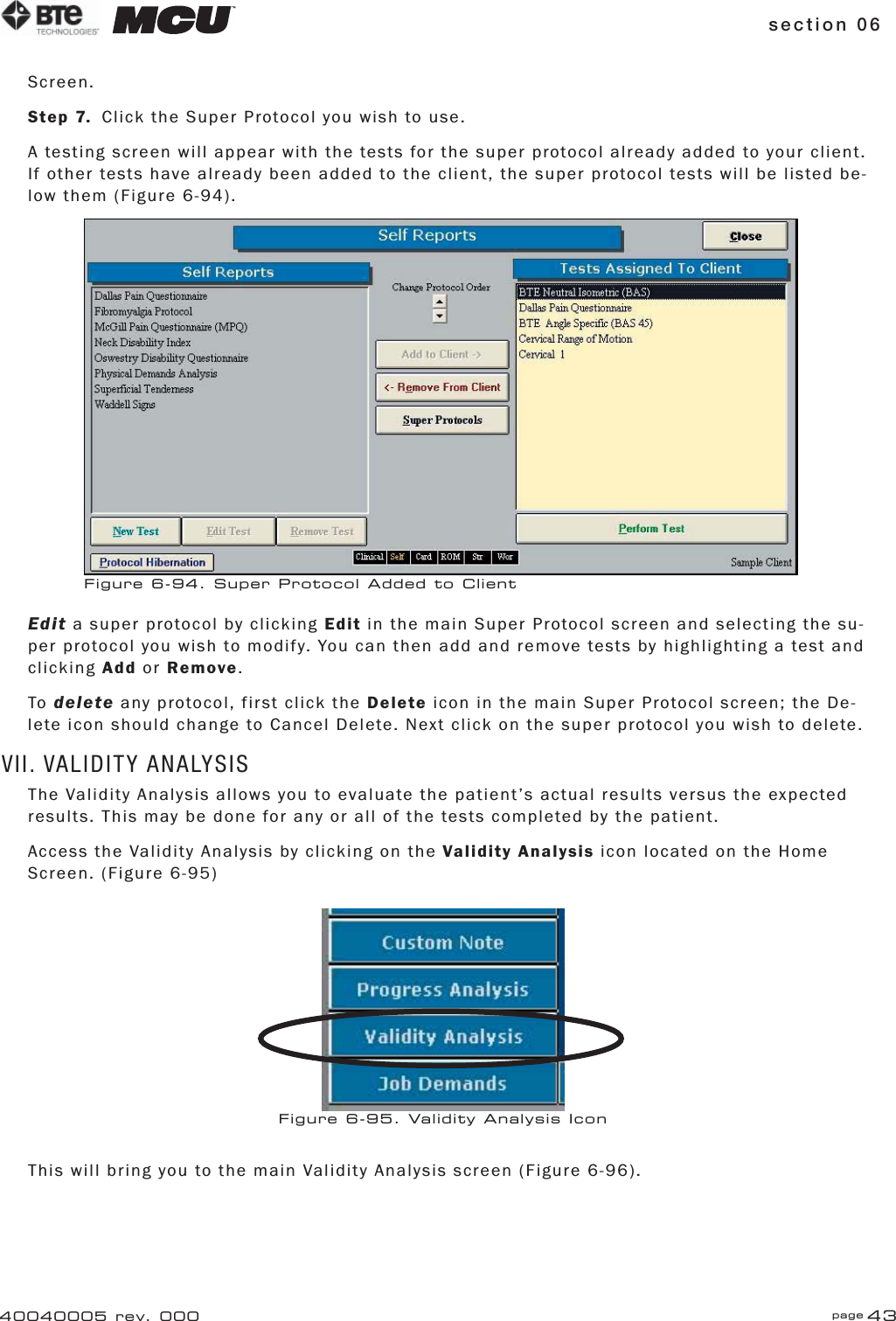
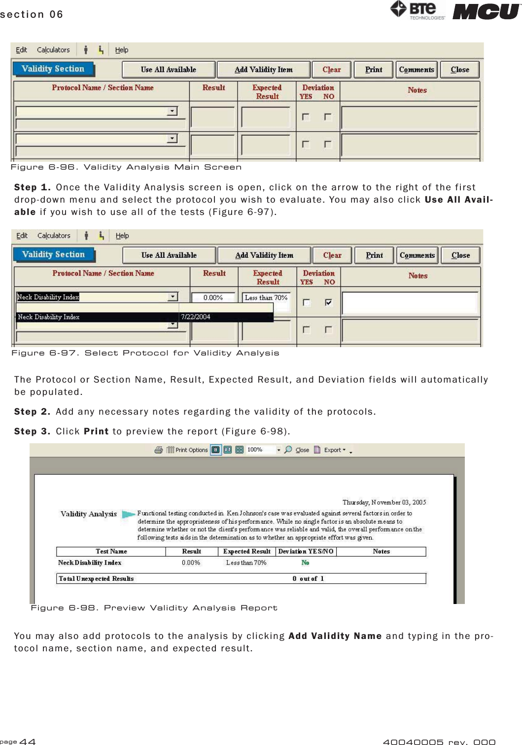
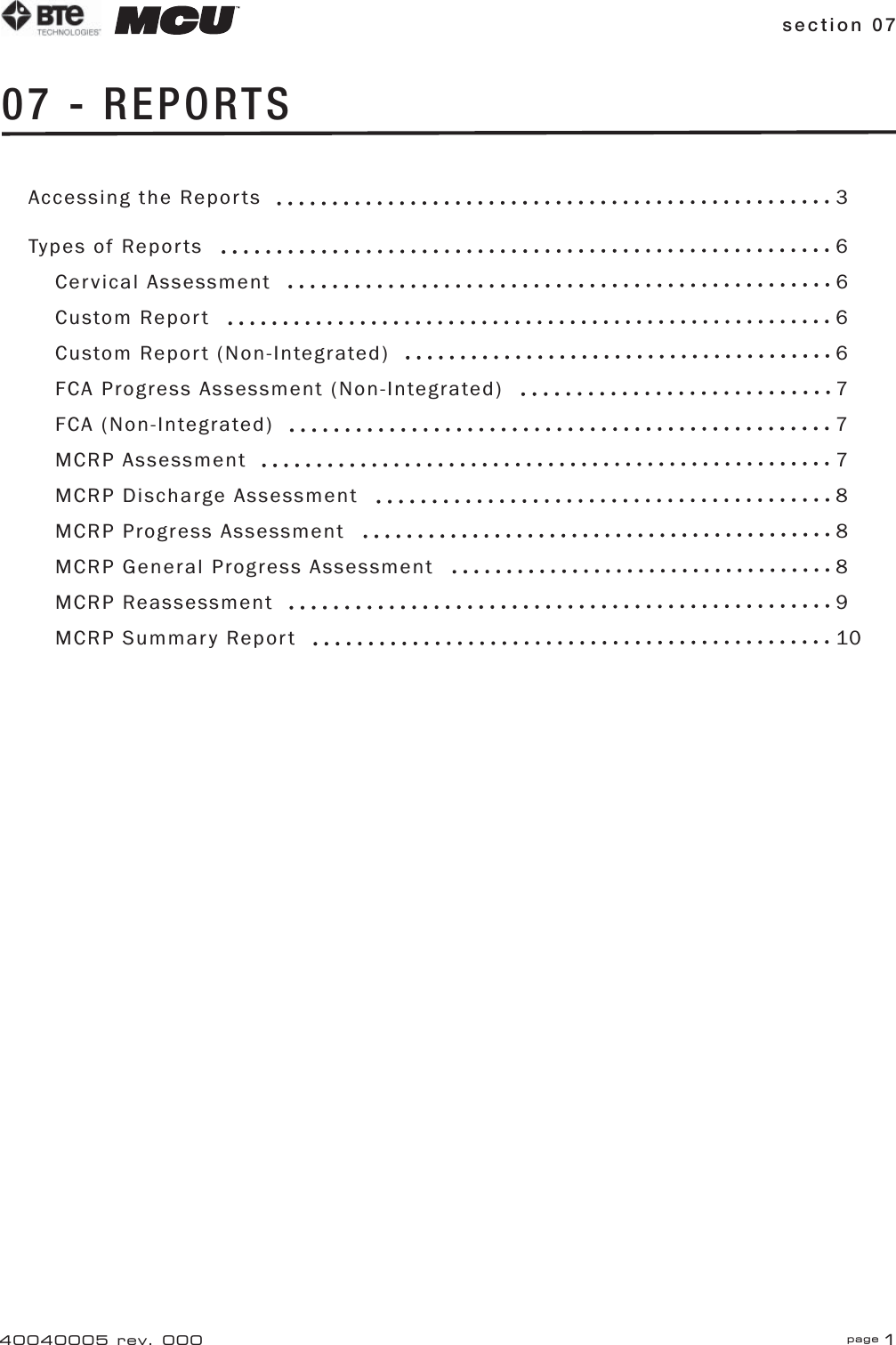


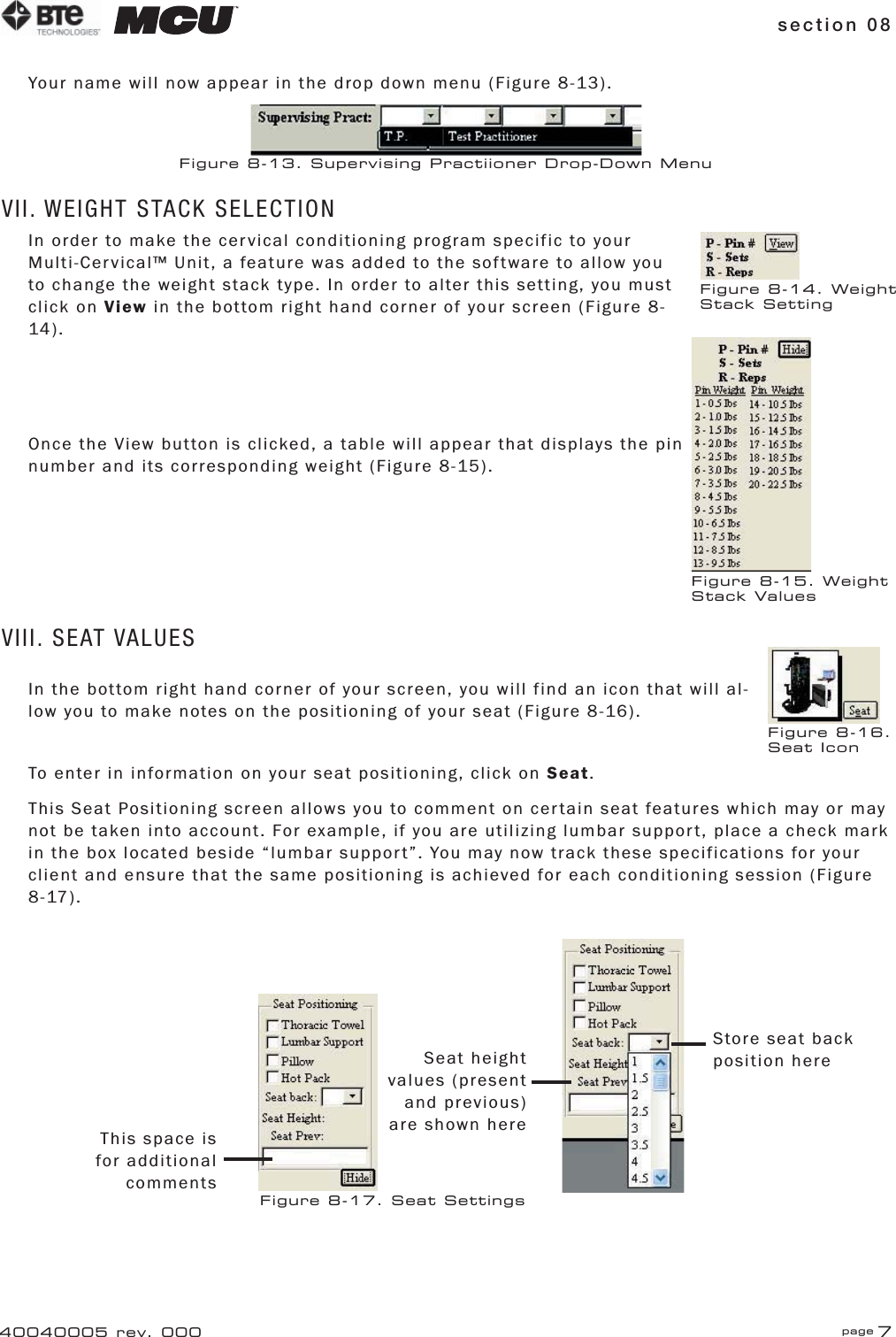
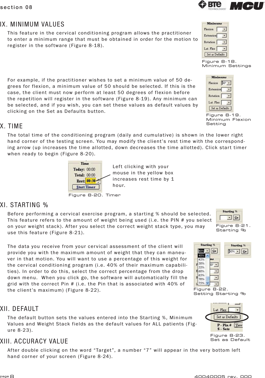
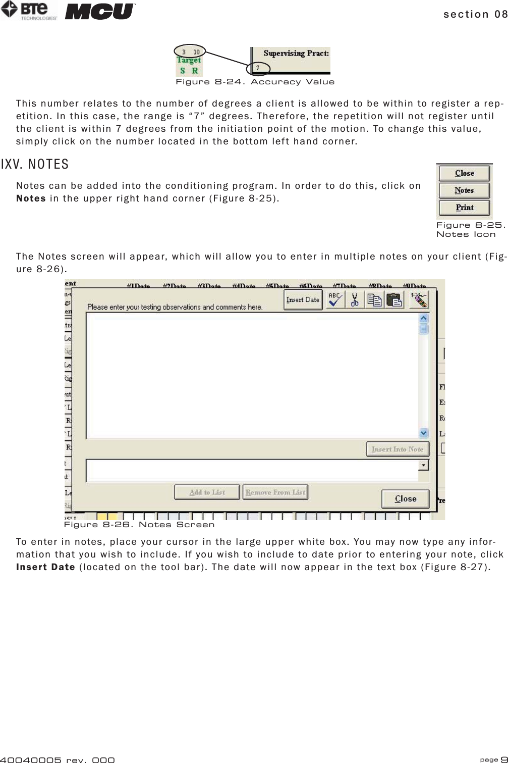

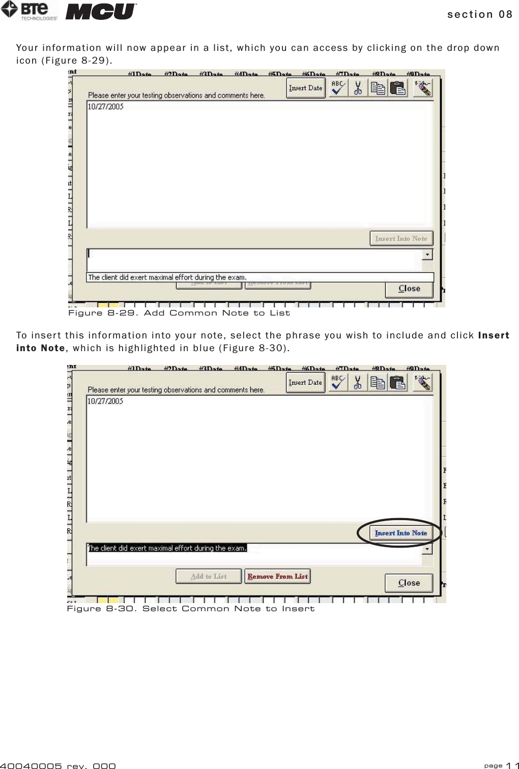
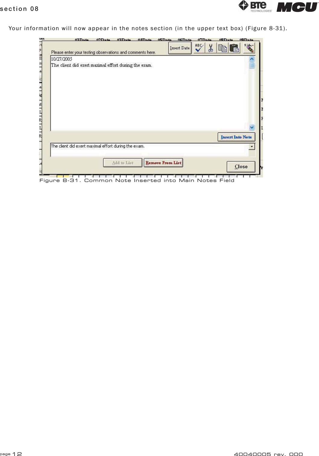


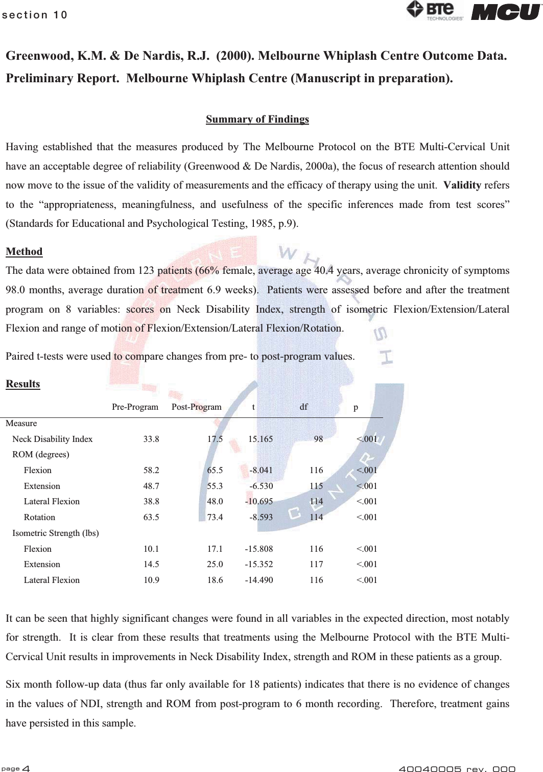
![section 10 page 540040005 rev. 000Greenwood, K.M. & De Nardis, R. (2000). An assessment of the reliability of measurements made using the Melbourne Protocol and the BTE Multi-Cervical Unit. Melbourne Whiplash Centre (Manuscript in preparation). Summary of FindingsThe reliability of a measurement refers to “the consistency, the reproducibility and the repeatability of the instrument or measurement procedure” (Richman, Makrides & Prince, 1980). The Reliability TrialTo assess the reliability of measures made using The Melbourne Protocol and the BTE Multi-Cervical Unit, a trial was designed in which 26 individuals (who did not have ailments involving the neck) were assessed by three therapists on two occasions each. The trial allowed assessment of inter-observer and intra-observer reliability. Results:Inter-Tester ReliabilityThe consistency of a measurement technique when used by different clinicians over time. xSystematic Difference between TherapistsResults indicate a good degree of agreement between therapists. All averages reported were within 3.3 degrees for ROM measurements and 0.8 lbs for strength measurements. xOrder of Testing EffectsThere were no systematic differences between the first, second and third measurements. Results indicate that there are no major “warm-up” or familiarisation of technique changes in value and further indicate that the pre-measurement trials conducted in the protocol are sufficient to rule out these effects. xRelationship Between the Therapists’ Scores – CorrelationsCorrelation coefficients are high (.747 to .949 [approaching 1.0]) indicating good inter-observer reliability. xRelationship Between Therapists’ Scores – ICCsIntra-Class correlation coefficients are high (.767 to .930 [approaching 1.0]) indicating good inter-observer reliability. xStandard Error of MeasurementSEM’s are low (1.56 to 4.10) indicating good inter-therapist reliability. Intra-Tester Reliability The consistency of a measurement technique when used by the same clinician over time. xSystematic Changes Over TimeNo systematic differences were identified in scores over time. xRelationship Between the Therapists’ Scores – Test-Retest CorrelationsThe majority of the correlation coefficients are high (.667 to .895 [approaching 1.0]) indicating good test-retest reliability. ROM extension scores were lower (.529 to .747) indicating some attention is required for this particular measure. xTest-Retest Reliability of Therapists’ Scores – ICCsThe majority of the ICC’s are high (.654 to .879 [approaching 1.0]) indicating good test-retest reliability. Again ROM extension was lower (.531 to .742). xStandard Error of MeasurementSEM’s are low (1.54 to 5.73) indicating good test-retest reliability. xMinimum Detectable Change – Test-RetestThe same therapist over a one week period can reliably detect changes of around 10 degrees in ROM and around 5lbs in strength.](https://usermanual.wiki/BTE-Technologies/WER-1.Users-Manul-Part-II/User-Guide-640626-Page-36.png)