BTE Technologies WER-1 MCU Wireless User Manual 40040005 01 Installation and Setup indd

BTE Technologies, Inc. MCU Wireless 40040005 01 Installation and Setup indd

Contents

Installation Manual

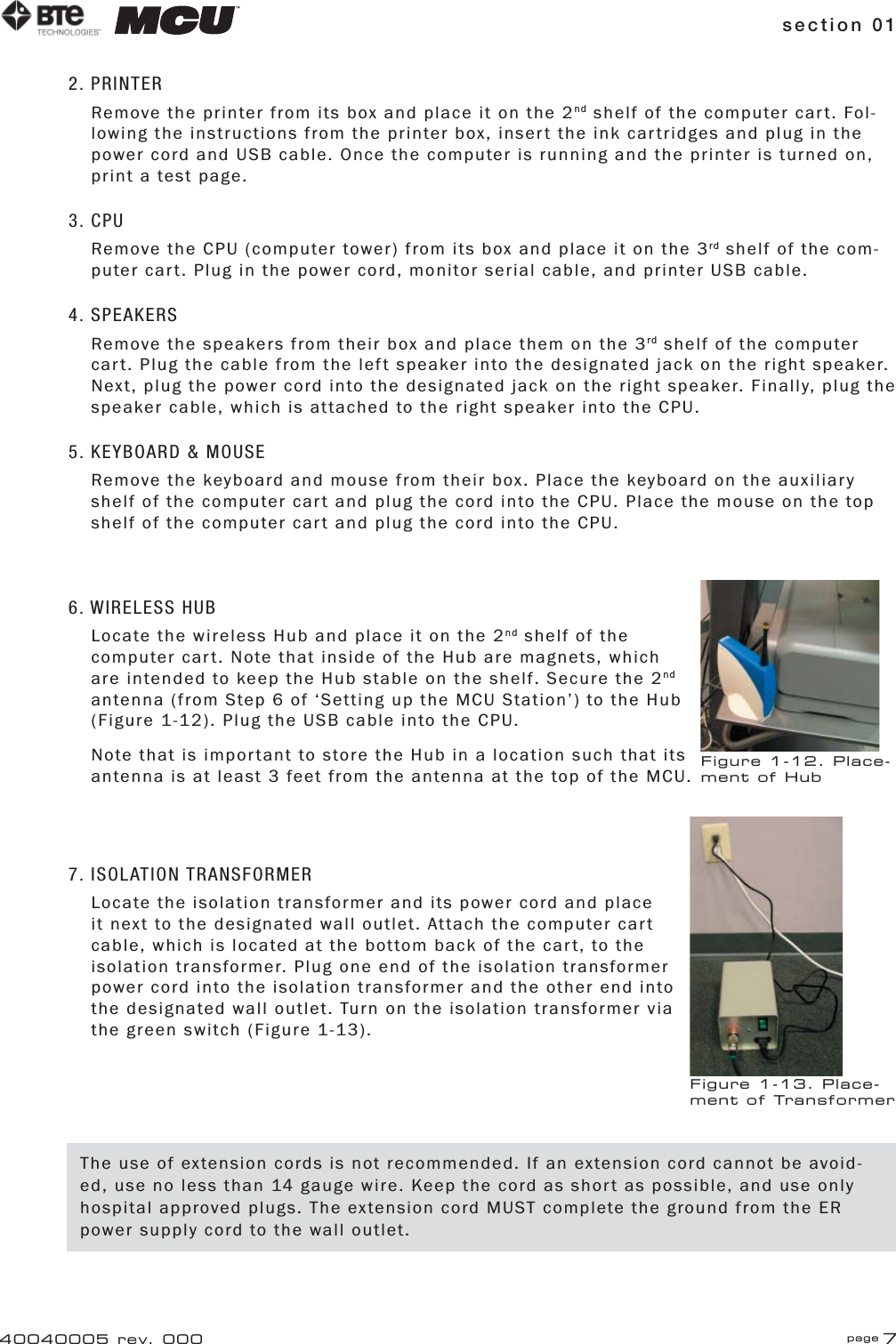
section 01 page 740040005 rev. 0002. PRINTERRemove the printer from its box and place it on the 2nd shelf of the computer cart. Fol-lowing the instructions from the printer box, insert the ink cartridges and plug in the power cord and USB cable. Once the computer is running and the printer is turned on, print a test page.3. CPURemove the CPU (computer tower) from its box and place it on the 3rd shelf of the com-puter cart. Plug in the power cord, monitor serial cable, and printer USB cable.4. SPEAKERSRemove the speakers from their box and place them on the 3rd shelf of the computer cart. Plug the cable from the left speaker into the designated jack on the right speaker. Next, plug the power cord into the designated jack on the right speaker. Finally, plug the speaker cable, which is attached to the right speaker into the CPU.5. KEYBOARD & MOUSERemove the keyboard and mouse from their box. Place the keyboard on the auxiliary shelf of the computer cart and plug the cord into the CPU. Place the mouse on the top shelf of the computer cart and plug the cord into the CPU.6. WIRELESS HUBLocate the wireless Hub and place it on the 2nd shelf of the computer cart. Note that inside of the Hub are magnets, which are intended to keep the Hub stable on the shelf. Secure the 2nd antenna (from Step 6 of ‘Setting up the MCU Station’) to the Hub (Figure 1-12). Plug the USB cable into the CPU.Note that is important to store the Hub in a location such that its antenna is at least 3 feet from the antenna at the top of the MCU.7. ISOLATION TRANSFORMERLocate the isolation transformer and its power cord and place it next to the designated wall outlet. Attach the computer cart cable, which is located at the bottom back of the cart, to the isolation transformer. Plug one end of the isolation transformer power cord into the isolation transformer and the other end into the designated wall outlet. Turn on the isolation transformer via the green switch (Figure 1-13).Figure 1-12. Place-ment of HubFigure 1-13. Place-ment of TransformerThe use of extension cords is not recommended. If an extension cord cannot be avoid-ed, use no less than 14 gauge wire. Keep the cord as short as possible, and use only hospital approved plugs. The extension cord MUST complete the ground from the ER power supply cord to the wall outlet.

Navigation menu