BTE Technologies WER-1 MCU Wireless User Manual 40040005 rev 000
BTE Technologies, Inc. MCU Wireless 40040005 rev 000
UserManual.wiki
>
BTE Technologies
>
WER-1 User Manual
>
Users Manual Part I
Contents
1.
Installation Manual
2.
Users Manual Part I
3.
Users Manul Part II
Users Manual Part I
Navigation menu
Upload a User Manual
Namespaces
Wiki Guide
HTML
PDF
Info
Views
User Manual
Discussion / Help
Navigation


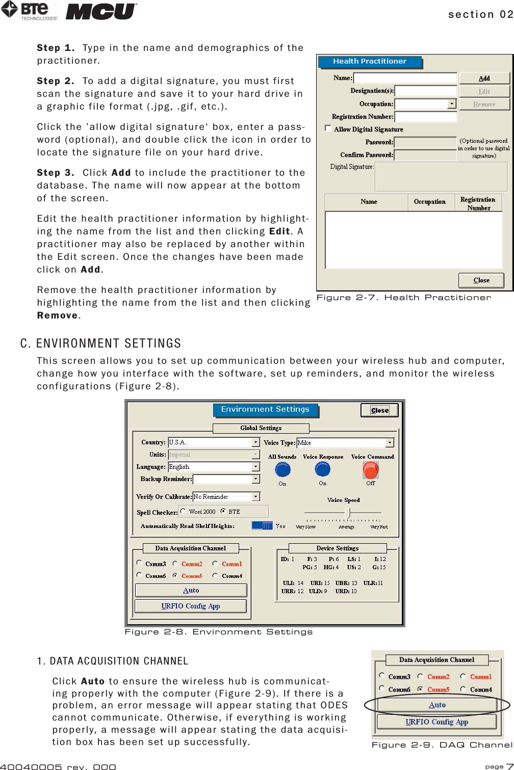
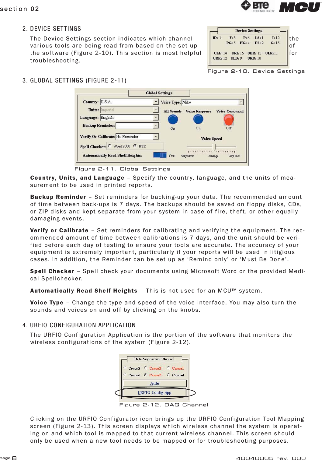
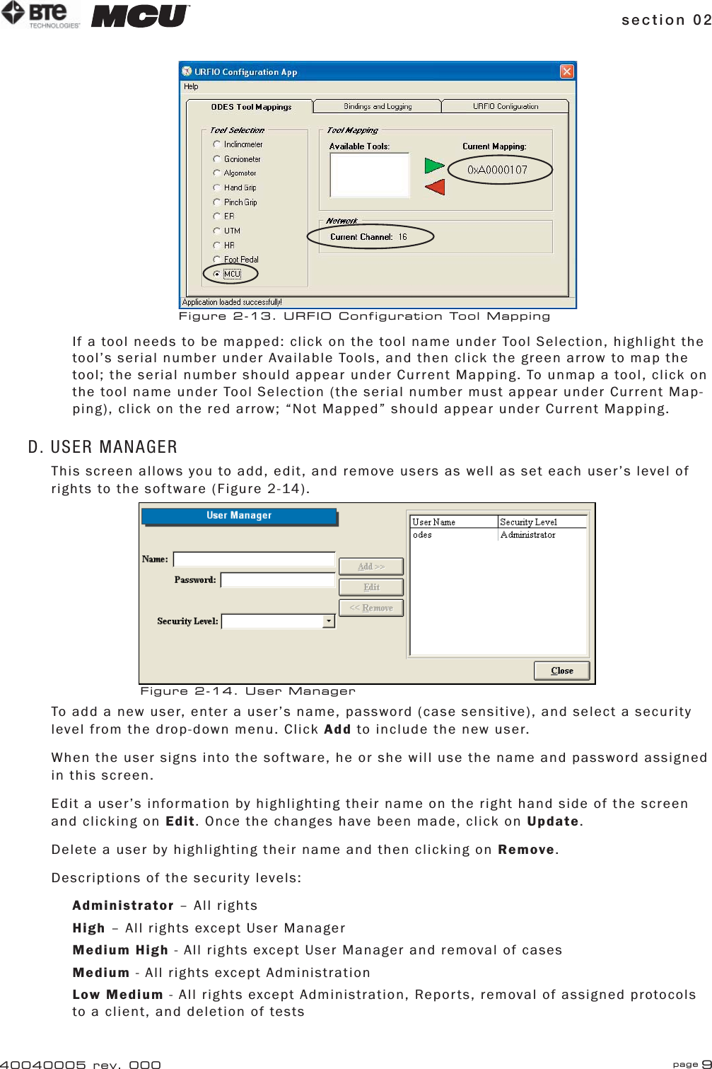
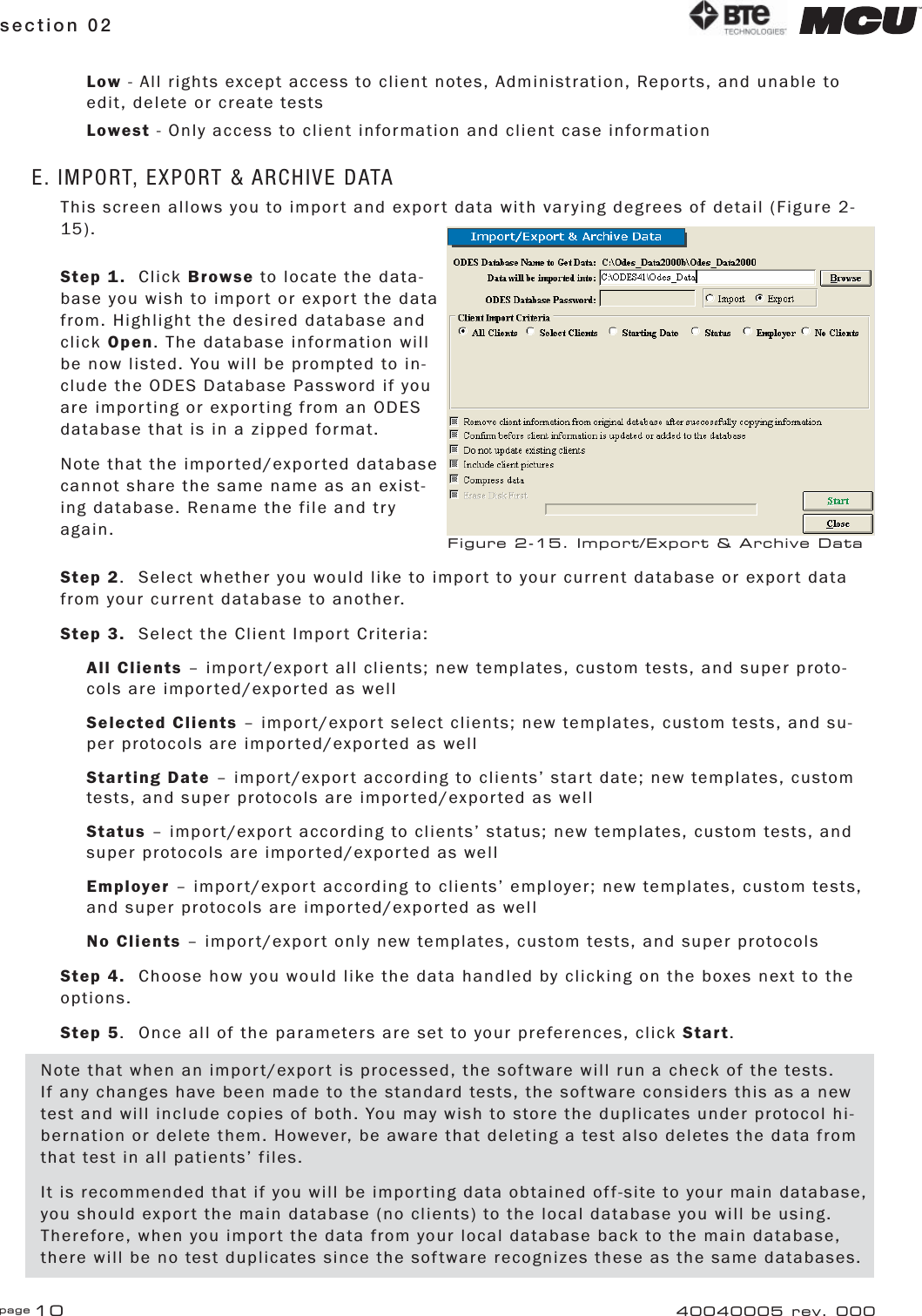
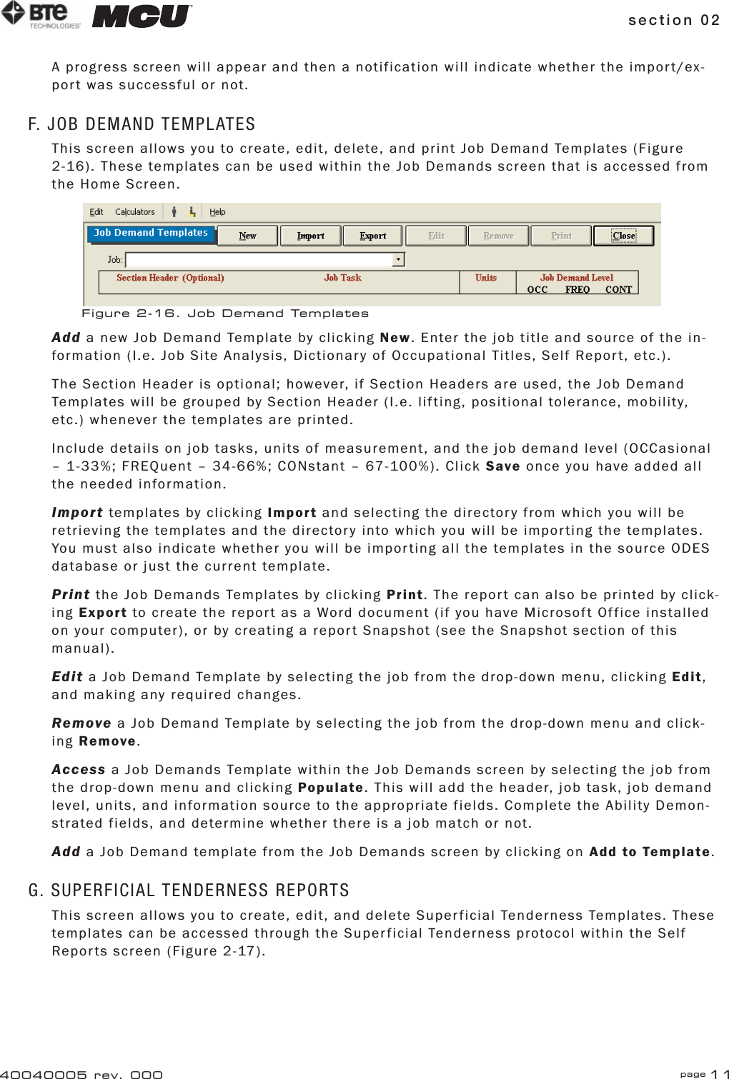


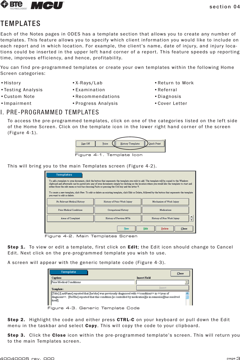
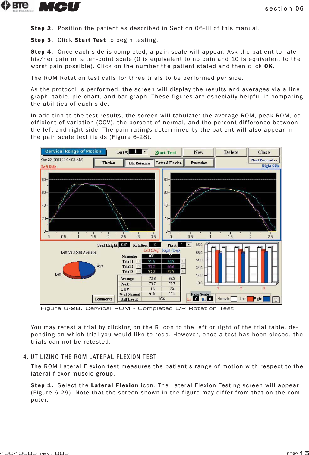
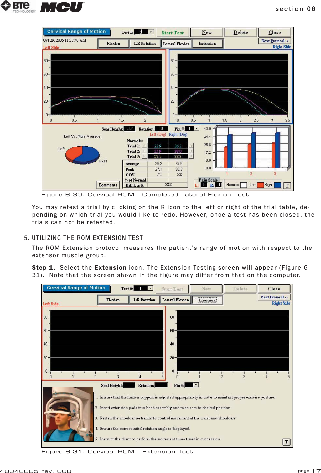
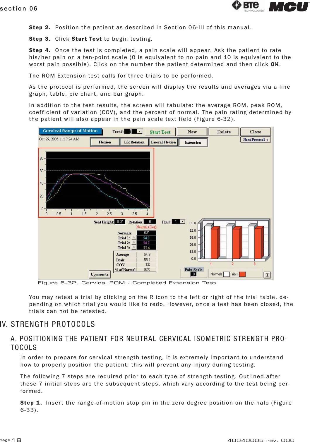
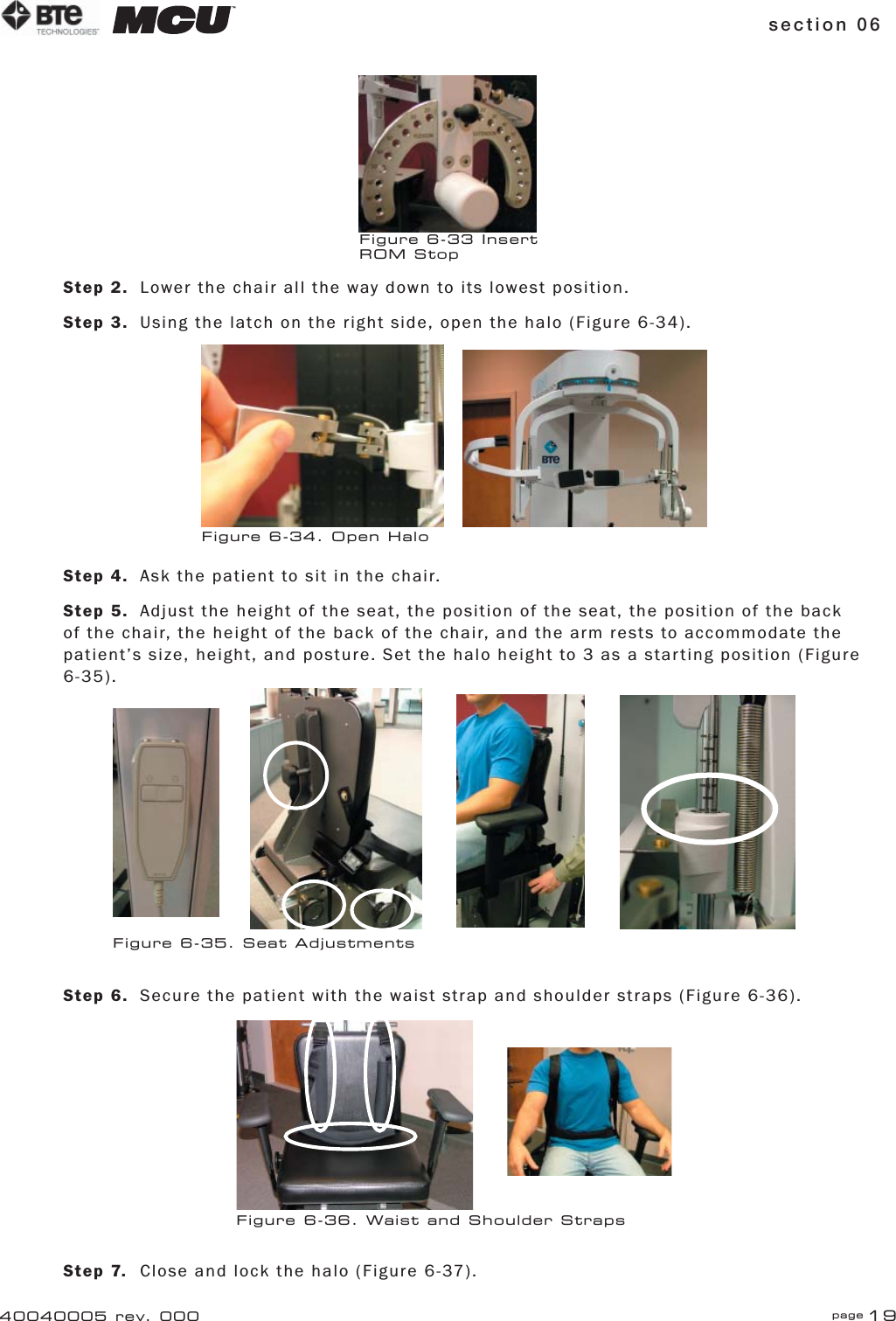
![page 4section 04 40040005 rev. 000Step 4. Click Cancel Edit and then select the template you just viewed. This will bring you to the corresponding screen (Figure 4-4).Step 5. While in the home template screen, click within the white text box to place the cursor and paste in the code. You can paste by either pressing CTRL-V on your keyboard, clicking on the Paste icon within the home template screen, or pulling down the Edit menu in the taskbar selecting Paste (Figure 4-5).The code will be updated with the client’s information, but you must still populate the fields with carets and select which bracketed options apply.Note that any client demographics within brackets – [ ] – will automatically be populated with the client’s information that has been entered in the client information and case screens (i.e. title, name, gender). All other information which is bracketed but isn’t available from these screens will remain intact until deleted. This is typically used when there are several options to describe the situation and you must pick the most applicable one (i.e. condition is either controlled by medication, in remission, or has resolved itself). Any text within carets – << >> – is intended to alert the evaluator to fill in the information (i.e. name of the condition and year of the diagnosis).Edit a pre-programmed template by clicking Edit in the main Templates screen and selecting the template you wish to modify. You can then add fields by selecting the desired field from the Insert Field drop down menu and clicking Insert or delete fields using the delete key on your keyboard. The text may also be modified as you see fit.To delete any template, first click the Delete icon in the main Templates screen; the Delete icon should change to Cancel Delete. Next click on the pre-programmed template you wish to delete.II. CUSTOM TEMPLATESTo create or access a custom template, click on one of the categories listed on the left side of the Home Screen. Click on the template icon in the lower right hand corner of the screen (Fig-ure 4-5).Figure 4-5. Updated Template CodeFigure 4-6. Template IconFigure 4-4. Blank Notes Screen](https://usermanual.wiki/BTE-Technologies/WER-1.Users-Manual-Part-I/User-Guide-640625-Page-46.png)
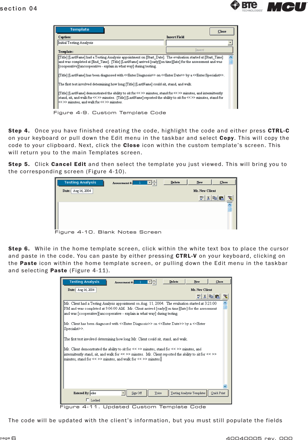
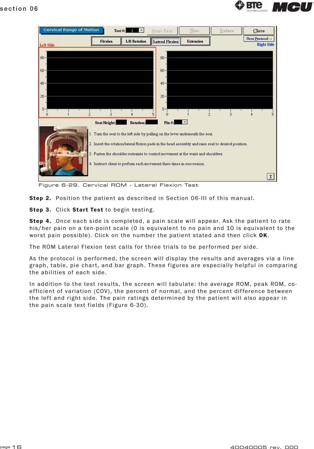
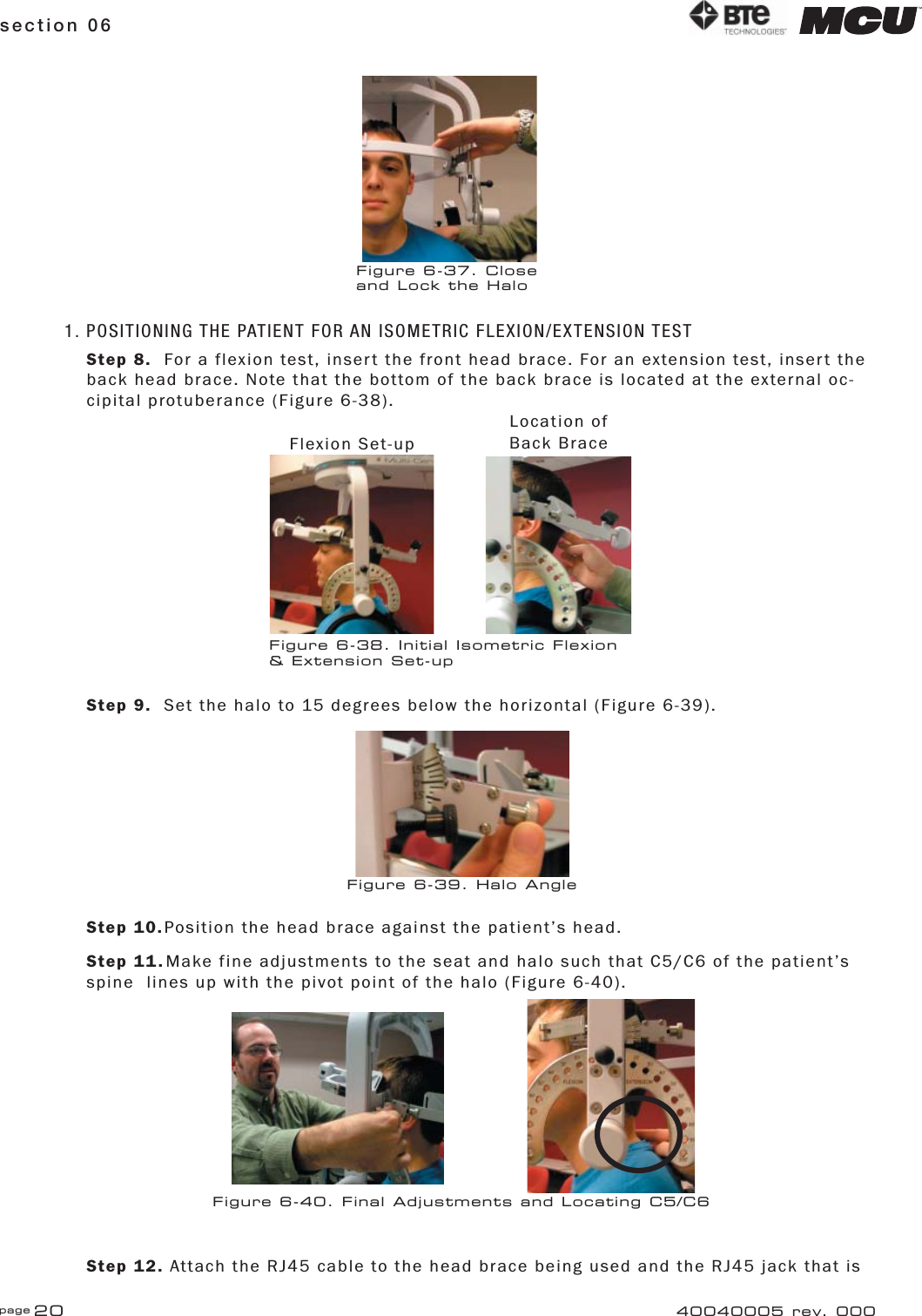
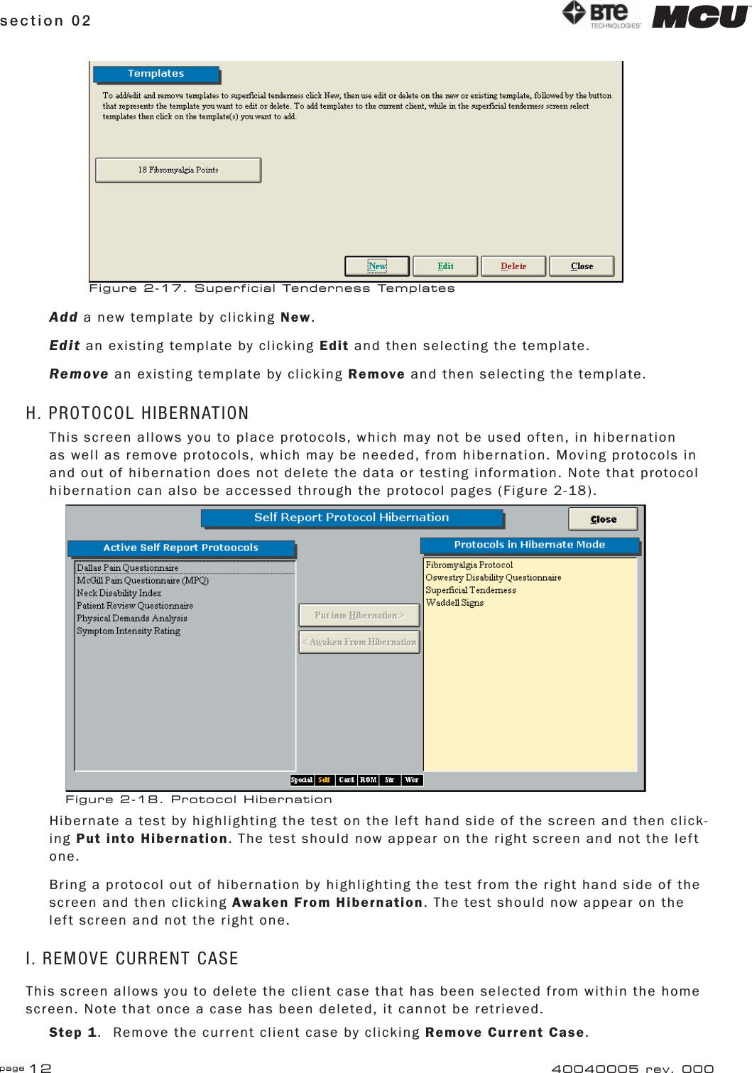
![section 04 page 540040005 rev. 000This will bring you to the main Templates screen (Figure 4-7).Step 1. Create a new template by clicking on New. A new icon will appear within the main Templates screen.Step 2. To view the template, first click on Edit; the Edit icon should change to Cancel Edit. Next click on the template you just created.A screen will appear with a blank text box (Figure 4-8).Within this screen you can change the name of the template as well as create the generic code by inserting fields and typing text.Step 3. Begin by writing what you wish to include in the report, but use the merge fields when you would like information automatically populated. The software already includes multiple pre-programmed merge fields which are listed under the Insert Field drop down menu.Insert a merge field by selecting the field from the Insert Field drop down menu and click-ing Insert. The merge field will be inserted where the text cursor is located. The merge field should have brackets – [ ] – around the text.You may create your own merge fields by typing the options you would like to include and plac-ing brackets around each one. This is useful when there are several options to describe the situation and you must pick the most applicable one (i.e. “client arrived [early][on time][late] for the assessment…”).You can also include characters which alert you to personalize a field for the client. This is useful when you need to include information which is different for every client but must be included in the report (i.e. “client has been diagnosed with <<Enter Diagnosis>> on <<Enter Date>> by a <<Enter Specialist>>…”). The pre-programmed templates use carets – << >> – to bring your attention to the field, but you may use any characters you like (Figure 4-9).Figure 4-7. Main Templates ScreenFigure 4-8. Blank Template](https://usermanual.wiki/BTE-Technologies/WER-1.Users-Manual-Part-I/User-Guide-640625-Page-47.png)