BTI Wireless 1900-160 High Power Multi.Carrier Power Amplifier User Manual
Bravo Tech (Shenzhen) Co. Ltd. High Power Multi.Carrier Power Amplifier Users Manual
Users Manual
Product Operation Introduction
LPA1900-160-SC01
V1.0
2009-07-06
Bravo Tech Inc.
All right reserved

HISTORY
Version Revision
description Prepared by Audited by Approved by
V1.00 First edition Xiao Hua Gan Cong HaiBao
Content
Part A, Summary.........................................................................4
Part B, Connector and definition................................................4
Part C, LED Indication ................................................................ 6
Part D, Specifications .................................................................. 6
Part E, Declare ................................................................................7
Part F, Information to the User ........................................................ 8
Accessory, Sample of Test Procedure ......................................8
1、Test equipment set up .............................................................8
1). Signal generator:............................................................................8
2). Spectrum analyzer:........................................................................8
3). Power meter: .................................................................................9
4). Network analyzer ...........................................................................9
2、 test condition description ........................................................ 9
1). Power supply cables and connectors: .........................................9
3、 Checking item before testing ................................................. 9
4、RF performance test procedure:............................................10
1) Spectrum emission .......................................................................10
2) Gain flatness.................................................................................12
3) Gain Variation & Detect Accuracy & Current consumption
............................................................................................................13
Part A, Summary
Bravo Tech Inc’s newly introduced High Power Multi-Carrier Power Amplifier platform provides
higher downlink EIRP to extend the coverage of existing networks. This multi-carrier based product
platform can also work with customized BTS to extend capacity of original BTS with a low system
total cost. This product platform features:
• Available for UMTS band
• Support multi-carrier WCDMA signals, with mixed mode operation
• Output maximum power 160W, support carriers number up to 4.
• Very High System Efficiency
• Extensive product monitoring and control (local and remote)
• Centralized system control/display/alarms
• Great system reliability supported by architecture built-in redundancy
• Powered by 30VDCavailable
• Extensive protection for lightning, voltage surge, and any high failure rate assemblies
• Compact system size and light weight
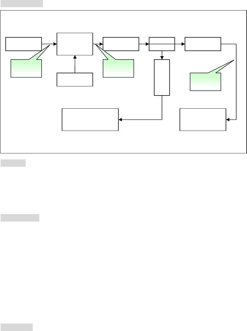
Part B, Connector and definition
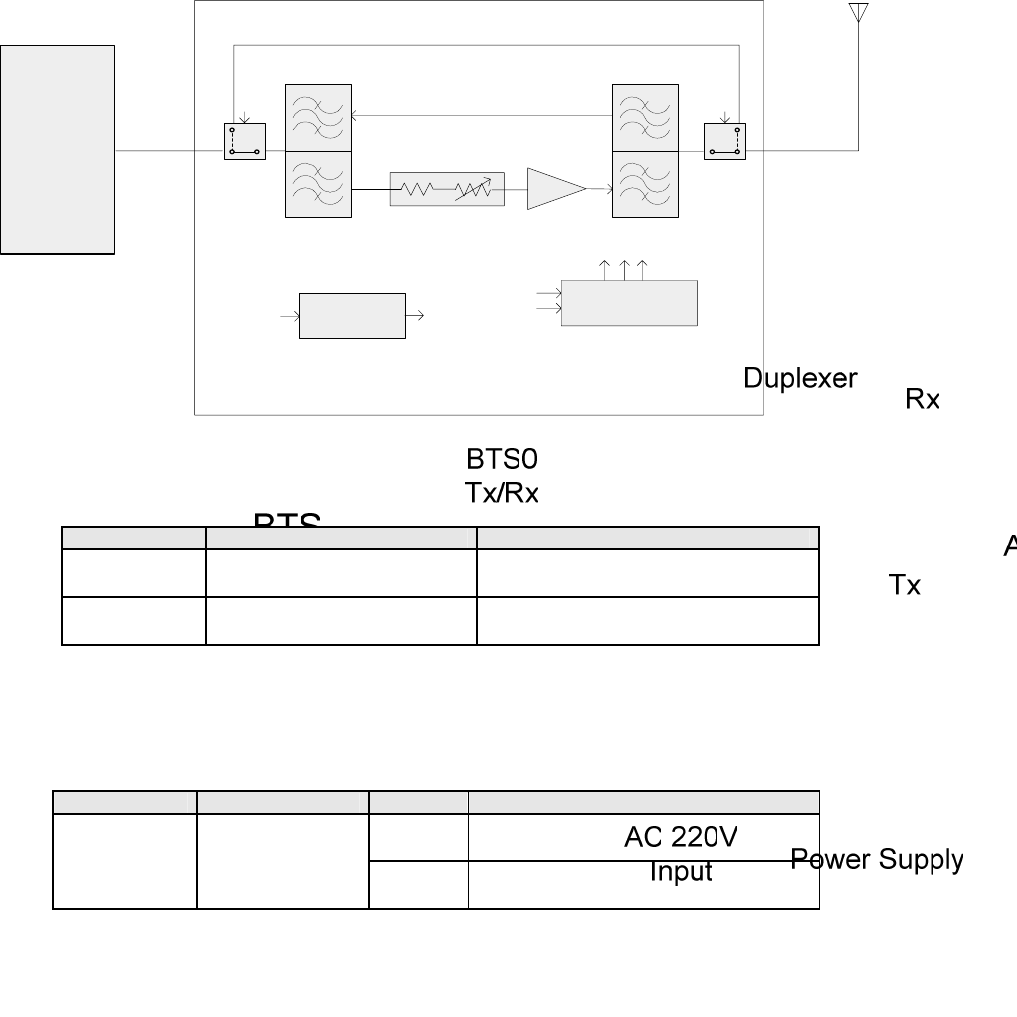
Block Diagram of MCPA in system
1、 RF Part
Port Name Type Warning
Input SMA Female (50Ω) Normal :-6.2dBm
Maximum input power +1dBm.
Output N Female (50Ω) Normal :52dBm
Maximum output power 52.5dBm.
2、 DC power
Port Name Type NO Warning
A1、A2 VDC type +30V, range 24~32V
DC IN
D-Sub type
DSCD175PS1M
(Male) A3、A4 GND to VDC
3、 Communication
Connector type: USB
Note: Manufacture use to debug.
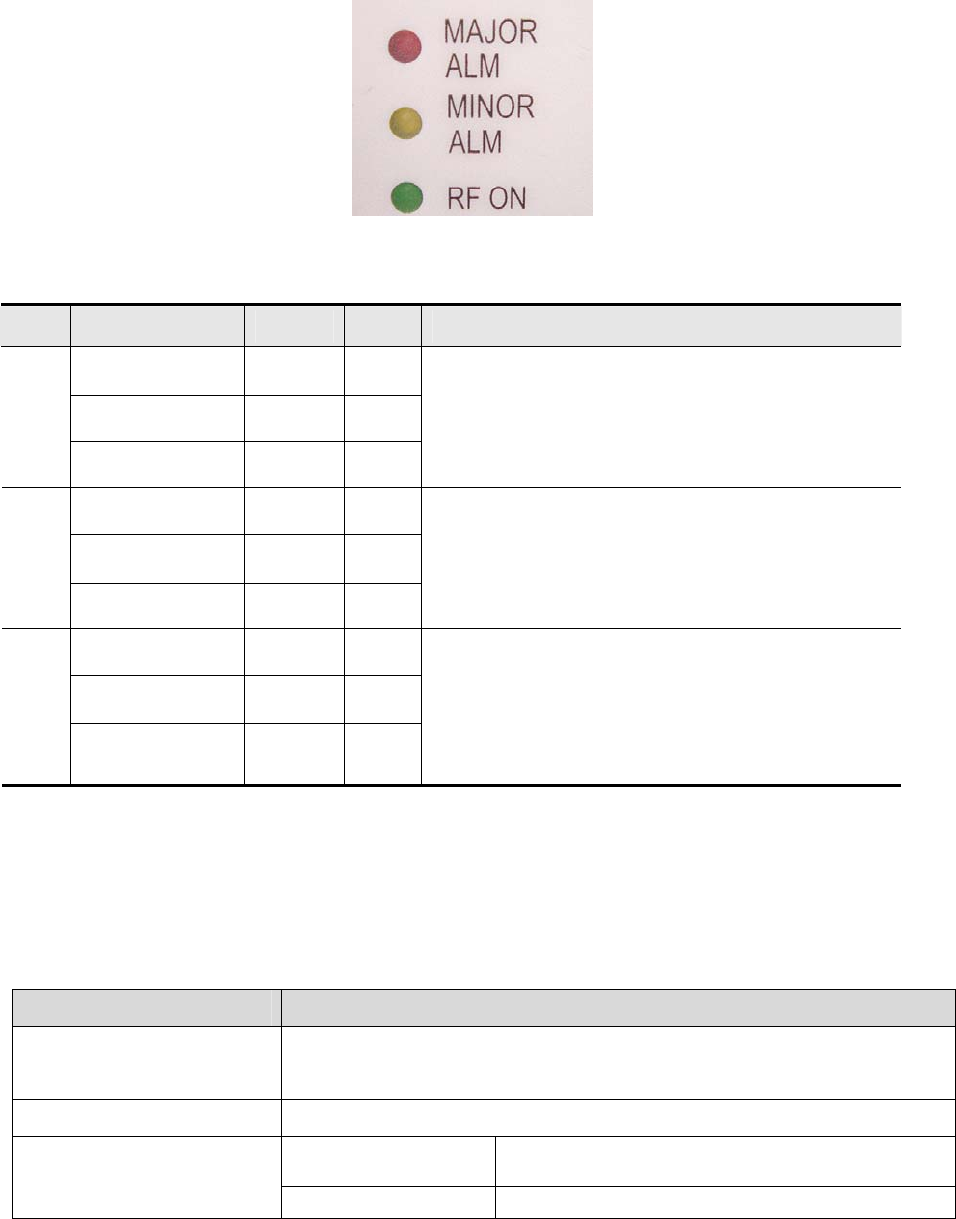
Part C, LED Indication
Figure 1 Power Amplifier Indicators
Table 1 Specification of Power Amplifier Indicator Lights
Item Label Color State Specification
MAJOR ALM Red On
MINOR ALM Yellow Off
1
RF ON Green Off
Power amplifier alarms and shuts down
MAJOR ALM Red Off
MINOR ALM Yellow On
2
RF ON Green Off
Power amplifier alarms but still works
MAJOR ALM Red Off
MINOR ALM Yellow Off
3
RF ON Green On
Power amplifier works normally
Part D, Specifications
1、 Electrical Specifications
PARAMETER SPECIFICATION
Frequency 1930 ~ 1990 MHz (Band: any 15MHz@customer require,
maximal band Δ60MHz)
Output Power 160Watts average max. (3FA, PAR:8.0dB), Any location in the BW.
<-48dBc @±5MHz
<-50dBc @±10MHz
@+29~ +31 Vdc
@-20℃~+50℃,Po=52dBm(max)
Spurious Emission
(3G 4Carriers) <-48dBc @±5MHz @+29 ~ +31 Vdc

<-53dBc @±10MHz @+25℃, Po=52dBm(max)
RF Gain 57.0 ± 1.0dB @ frequency range, +30Vdc, room temp.
Normal Operating Voltage +30Vdc±1.0Vdc
Operating Voltage +29Vdc ~ +31Vdc
RF Gain Variation over
Voltage & Temperature ±1.5dB @ +29≤Vsup≤+31V, -20℃ to +50℃
Gain Flatness Peak to Peak 0.2dB over any 5MHz
Input/Output Return Loss <-18dB
Output Protection Mismatch protected with isolator
Efficiency ≥15%@+30Volts, Po=+52dBm
Operating Temperature -30℃ to +55℃ (Air Temperature inside System),
Operating point Output power:52dBm ± 0.5dB
Operating range 6dB min
Input Power ALC
Over Power Output Pwr:52.5dBm ± 0.5dB
2. Alarm and Functions Specifications
TTL output for the alarm pins. Normal is High, Alarm is Low.
2.1. Over temperature alarm
Alarm and shutdown at 95℃ base temperature, auto-recover at 90℃ base temperat
ure.
2.2. Over power alarm
Alarm and shutdown when output power is over 52.5dBm, no auto-recover.
2.3. ALC
2.3.1. ALC level: 52±0.5dBm
2.3.2. ALC range: ≥6dB
2.4. VSWR alarm
Alarm and shutdown when reject is over 5, auto-recover at 3.
Part E, Declare
The device complies with Part 15 of the FCC rules. Operation is subject to the following two
conditions: (1) this device not cause harmful interference, and (2) this device must accept any
interference received, including interference that many cause undesired operation.
Part F, Information to the User
This equipment has been tested and found to comply with the limits for a Class A digital device,
pursuant to Part 15 of the FCC Rules. These limits are designed to provide reasonable protection
against harmful interference when the equipment is operated in a commercial environment. This
equipment generates, uses, and can radiate radio frequency energy and, if not installed and used in
accordance with the instruction manual, may cause harmful interference to radio communications.
Operation of this equipment in a residential area is likely to cause harmful interference in which case
the user will be required to correct the interference at his own expense.
Changes or modifications not expressly approved by the party responsible for compliance could
void to the user’s authority to operate the equipment.
This device must be installed by a professional installer.
The antenna(s) used for this transmitter must be fixed-mounted on outdoor permanent
structures.RF exposure compliance is addressed at the time of licensing, as required by the
responsible FCC Bureau(s) including antenna co-location requirements acc to §1.1307(b)(3).
Accessory, Sample of Test Procedure
1、Test equipment set up
1). Signal generator:
Agilent IFR3413
2). Spectrum analyzer:
ROHDE&SCHWARZ FSEA

3). Power meter:
Agilent E4418B/E8481A
4). Network analyzer
Agilent 8753E or R3765CH
2、 test condition description
1). Power supply cables and connectors:
Port Name Type NO DESCRIPTION
1、2 VDC
DC IN
D-Sub type
DSCD175PS1M
(Male) 3、4 GND to VDC
2).Alarm ports (D-SUB DSCD175PS1M male connector)
Pin#1: N.C
Pin#2: BTI (do not contact anywhere)
Pin#3: Over power alarm /over driver alarm /transistor fail alarm
Pin#4: Over temperature alarm
Pin#5: GND
Pin#6: RF output power indication
Pin#7: BTI (do not contact to anywhere)
Pin#8: VSWR alarm
Pin#9: Enable/Disable
3、 Checking item before testing
No seam on the surface of PA, the position and content of barcodes and labels are rig
ht.
Check the silk-screen of PA is correct and normal.
The connectors of power supply work normally and the poplars of positive and negative
are right.
RF connectors work normally.
Power switch is in the position of turnoff.
Turn on power supply and check the static current whose normal value should be 10A~
12A.
When the PA works with full power, the current should be 33A~35A.
4、RF performance test procedure:
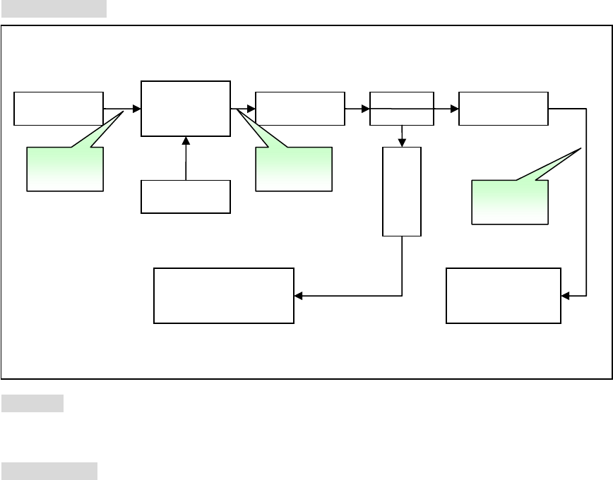
1) Spectrum emission
Test flow chart:
Purpose:
Check the quality of amplified signal.
Test setup list
Signal generator: Agilent IFR3413 or the same level instrumentation.
Power meter: Agilent E4418B or the same level instrumentation.
Spectrum analyzer: R&S FSEA or the same level instrumentation.
Power supply: 30V/50A
Attenuator: 30dB 500W 1PCS, 20dB 5W 2PCS,
Coupler: 60dB frequency range: 1930MHz~1990MHz
Signal
Generator
LPA1900-120
-SC01
10dB coupler
30dB
A
ttenuator
20dB
A
ttenuator
20dB
Attenuator
Power
Su
pp
l
y
Spectrum
Analyzer
Power
Meter
Figure 1
Cable1 Cable2
Cable3

RF cable
Instruction
1. Set up the structure according to the figure 1.
2. Signal generator setup:
signal type:1. 3G 3Carriers 3FA, PAR:8.0dB
2. ats_3gpp_fdd_fwd_tm1_64ch_sc0_v5pt1
3. Spectrum analyzer setup:
RBW→30KHz, VBW→300KHz, Center frequency: 1960MHz, SPAN→40MHz, Sweep
time: 1S Spectrum Analyzer’s offset value according the attenuation from PA output to
input port of spectrum analyzer.
4. Power meter must to be calibration and set the offset value according to attenuation
from PA output to power sensor.
5. Input PA voltage setup +30V.
6. Turn on the signal generator.
7. Than confirm standard ACLR peculiarity.
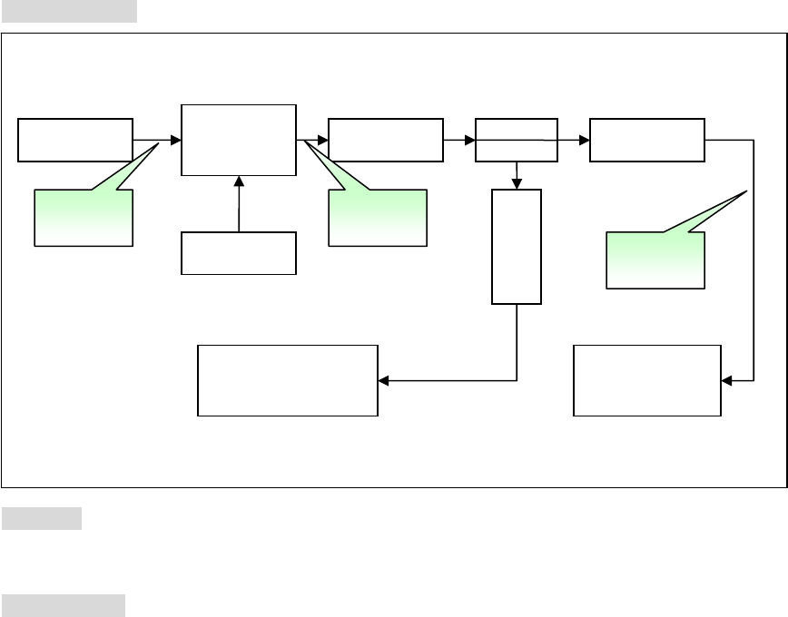
2) Gain flatness
Test flow chart:
Purpose:
Check the gain at different frequency point.
Test setup list
Signal generator: IFR3413 or the same level instrumentation.
Power meter: Agilent E4418B or the same level instrumentation.
Spectrum analyzer: R&S FSEA or the same level instrumentation.
Power supply: 30V/50A
Attenuator: 30dB 500W 1PCS, 20dB 5W 2PCS,
Coupler: 60dB frequency range: 1930MHz~1990MHz
RF cable
Signal
Generator
LPA19100-16
0-SC01
10dB coupler
30dB
A
ttenuator
20dB
A
ttenuator
20dB
Attenuator
Power
Su
pp
l
y
Spectrum
Analyzer
Power
Meter
Figure 4
Cable1 Cable2
Cable3
3) Gain Variation & Detect Accuracy & Current consumption
Test flow chart:
Purpose:
Check the variation of gain over voltage.
Measure the difference between forward power and detect power.
Measure the efficiency of PA.
Test setup list
Signal generator: IFR3413 or the same level instrumentation.
Power meter: Agilent E4418B or the same level instrumentation.
Spectrum analyzer: R&S FSEA or the same level instrumentation.
Power supply: 30V/50A
Attenuator: 30dB 500W 1PCS, 20dB 5W 2PCS,
Coupler: 60dB frequency range: 1930MHz~1990MHz
RF cable
Instruction
1. Set up the structure according to the figure 5.
Signal
Generator
LPA1900-160
-SC01
10dB coupler
30dB
A
ttenuator
20dB
A
ttenuator
20dB
Attenuator
Power
Su
pp
l
y
Spectrum
Analyzer
Power
Meter
Figure 5
Cable1 Cable2
Cable3
2. Signal generator setup:
3. Spectrum analyzer setup:
RBW→30KHz, VBW→300KHz, Center frequency is 1960MHz, SPAN→40MHz, and
Spectrum Analyzer’s offset value according the attenuation from PA output to input port of
spectrum analyzer.
4. Power meter must to be calibration and set the offset value according to attenuation
from PA output to power sensor.
5. Input PA voltage setup +30V.
6. Turn on the signal generator; adjust the output power from -6.2dBm to -23dBm with
-1dB step.
7. Read out the output power from the power meter and do subtractions of each gain
and get the gain Variation.
9. Compare the value on the power meter with the value shown on GUI, and then get
the accuracy for different frequency range and different carriers.