BTI Wireless DAS2100A80RUM 2.1GHz AWS Band 80W Remote Unit on BTI DAS system User Manual
Bravo Tech (Shenzhen) Co. Ltd. 2.1GHz AWS Band 80W Remote Unit on BTI DAS system Users Manual
UserManual.wiki
>
BTI Wireless
>
DAS2100A80RUM User Manual
Users Manual
Navigation menu
Upload a User Manual
Namespaces
Wiki Guide
HTML
PDF
Info
Views
User Manual
Discussion / Help
Navigation


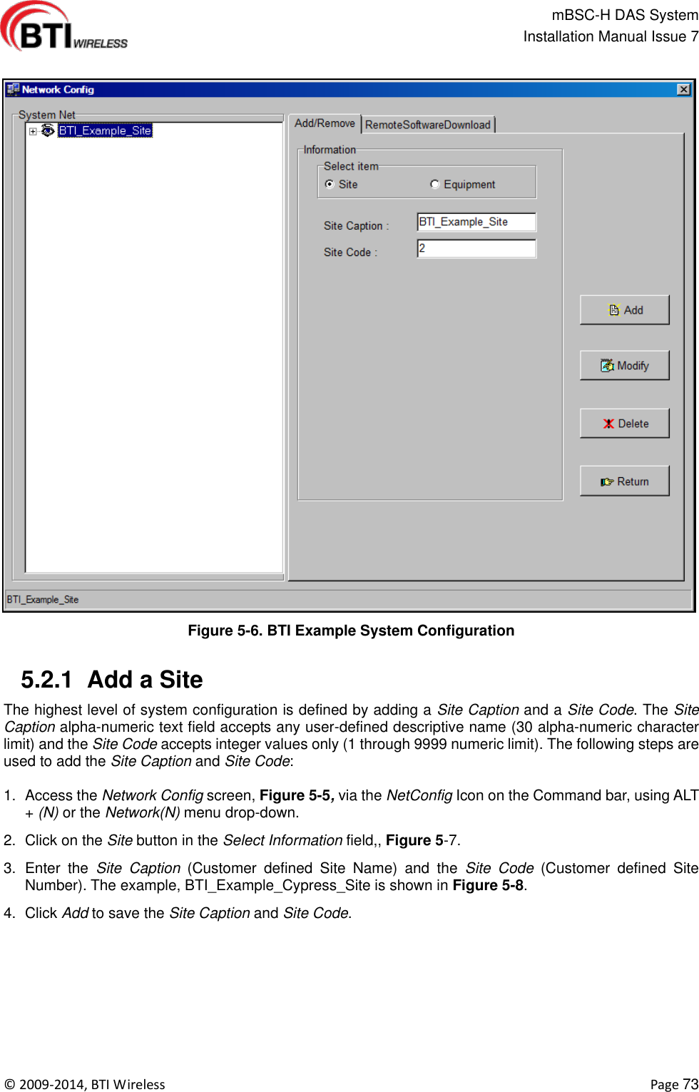
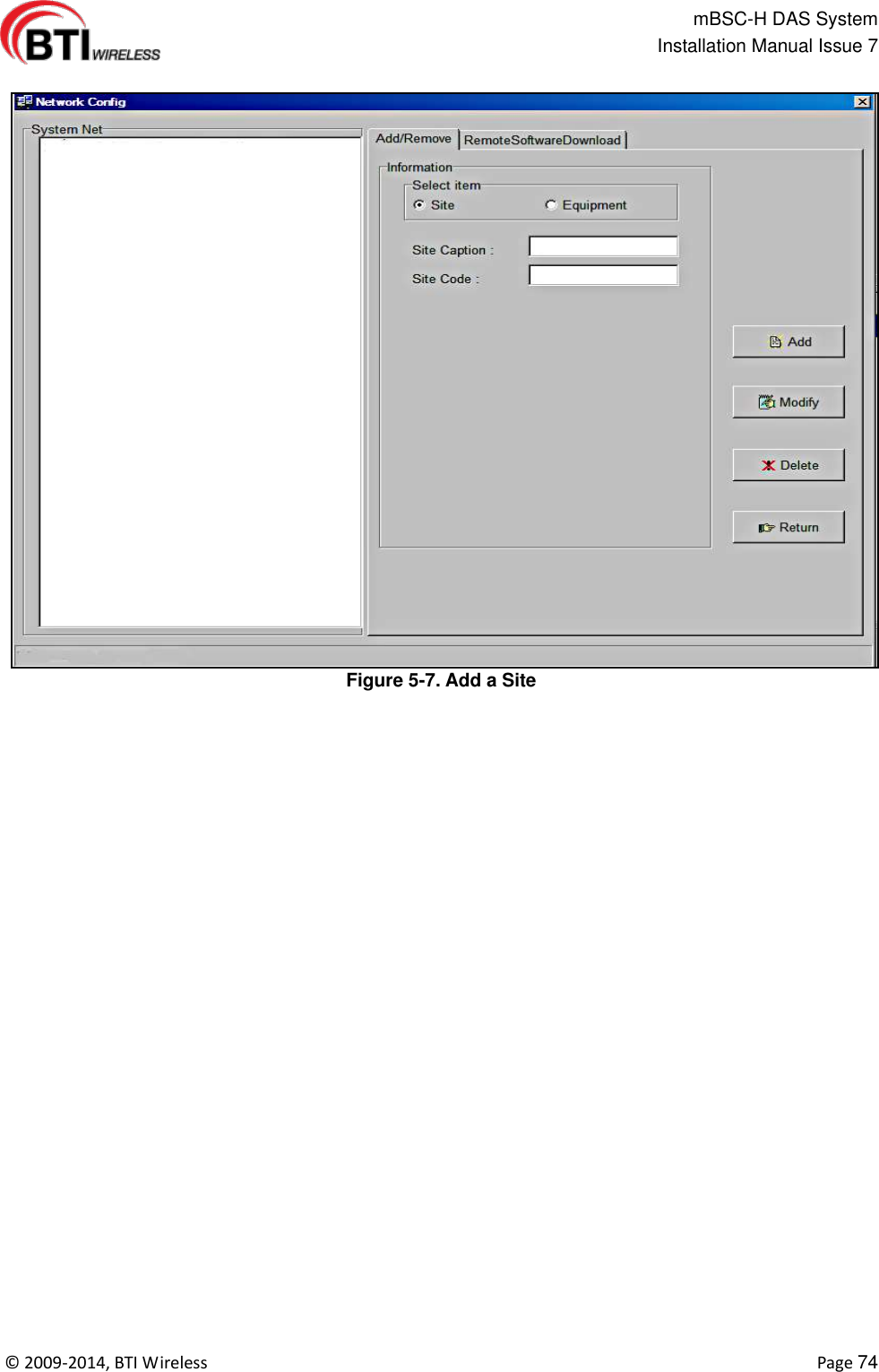
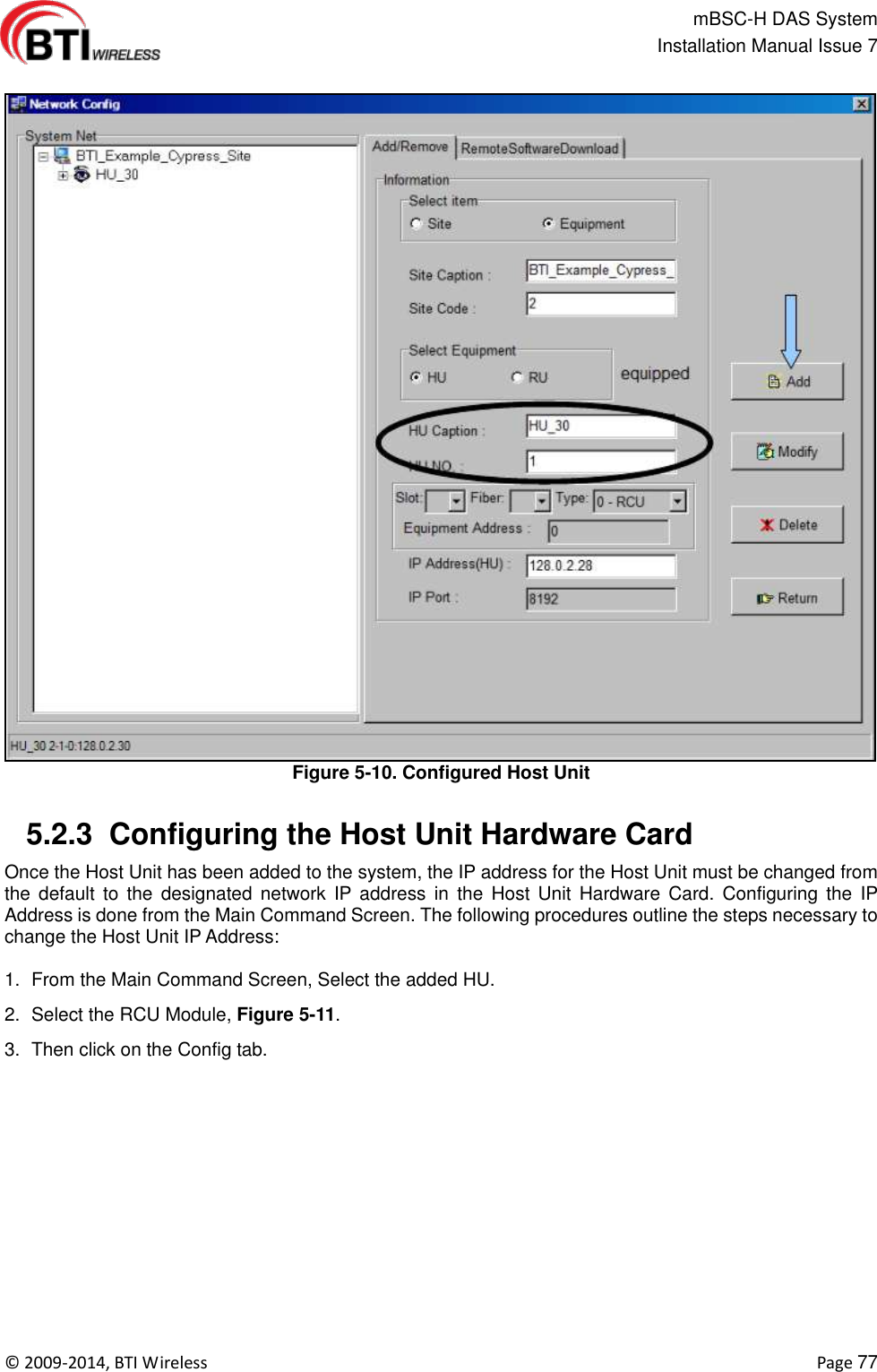
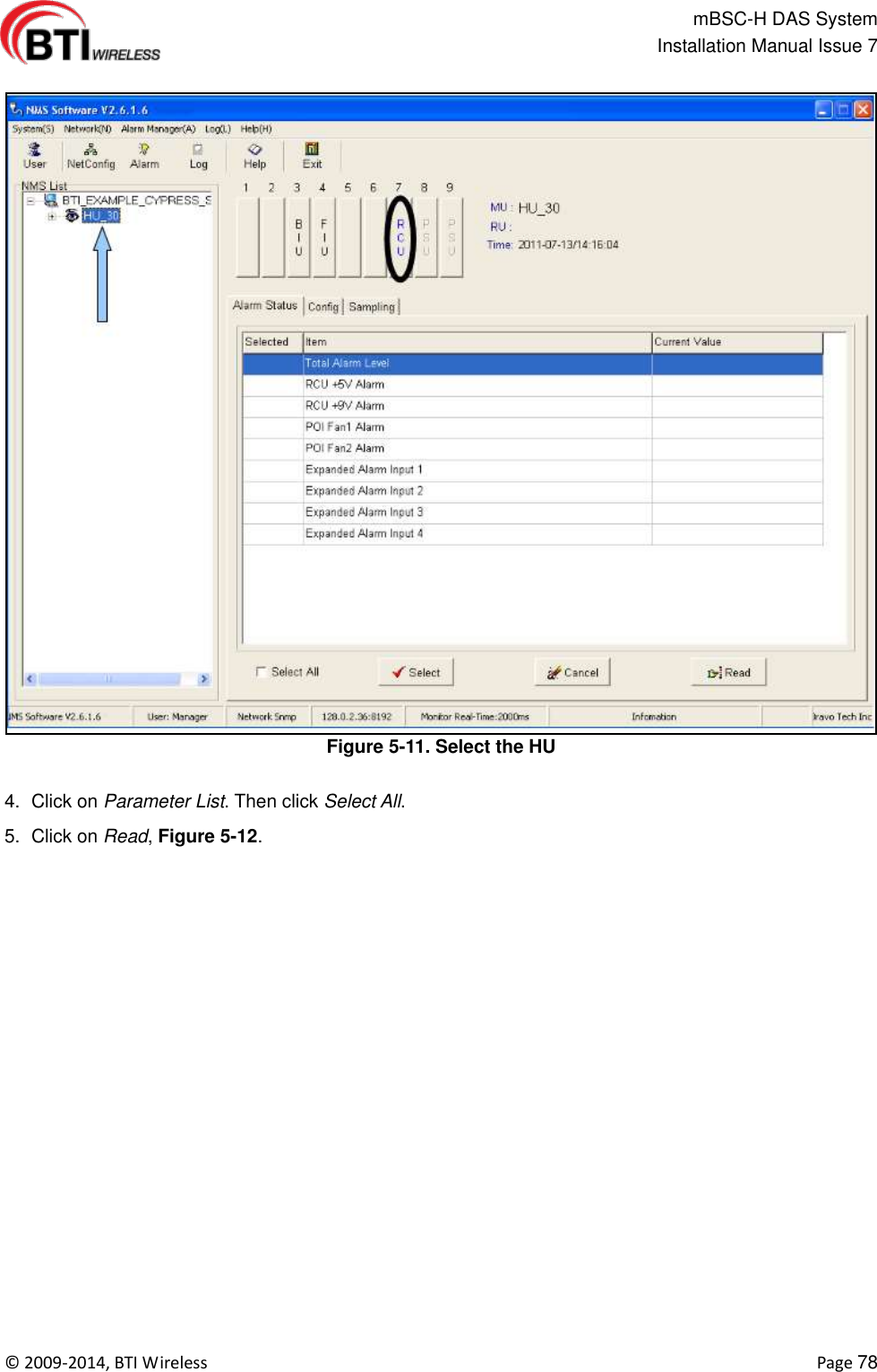
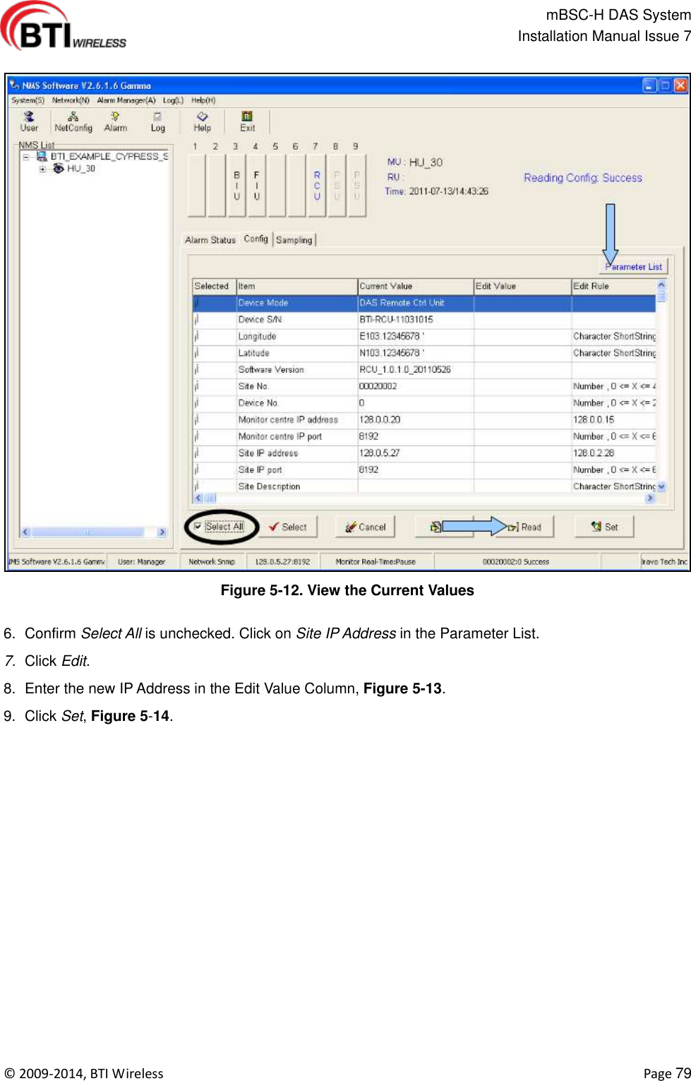
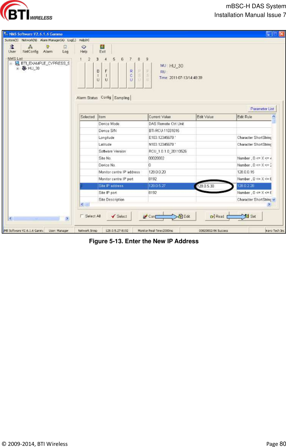
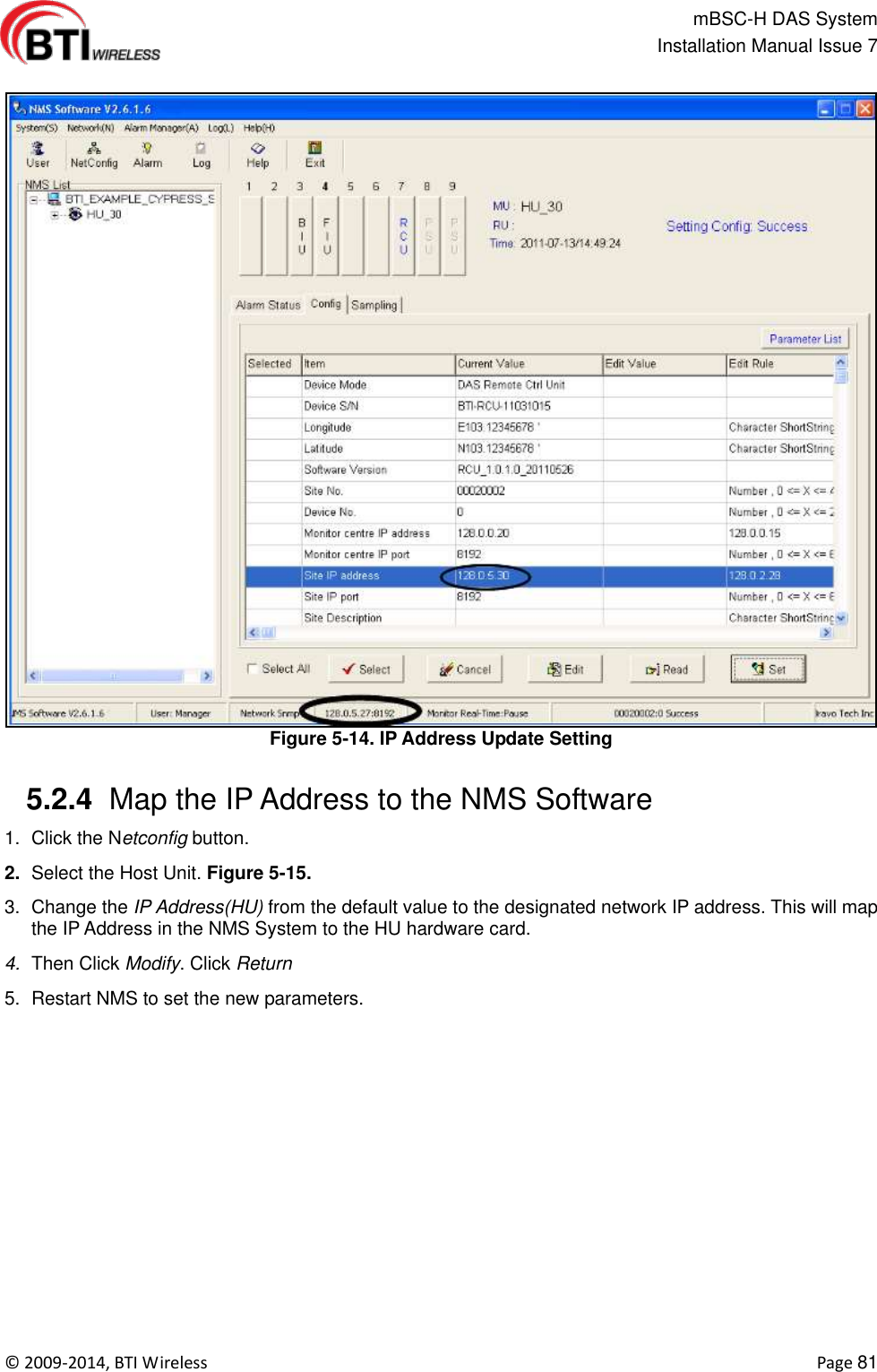
![mBSC-H DAS System Installation Manual Issue 7 © 2009-2014, BTI Wireless Page 63 Figure 4-46. System Parameter Screen 4.4.7 Firmware Update DAS components periodically require firmware updates. The following list of components may require periodic firmware updates: BIU FIU PA RCU Remote Unit A notification email is sent with the firmware update attached as a file to the email. The following procedures detail the firmware update process: 1. Verify the email is genuine and the file attachment is safe for download. The sent file will be named in the following manner and have a file extension of .s: DAS8345_[Component]_[Version].s 2. Download the attached file to any chosen folder or the desktop. Note the folder name, if saved to a designated folder.](https://usermanual.wiki/BTI-Wireless/DAS2100A80RUM/User-Guide-2297657-Page-63.png)
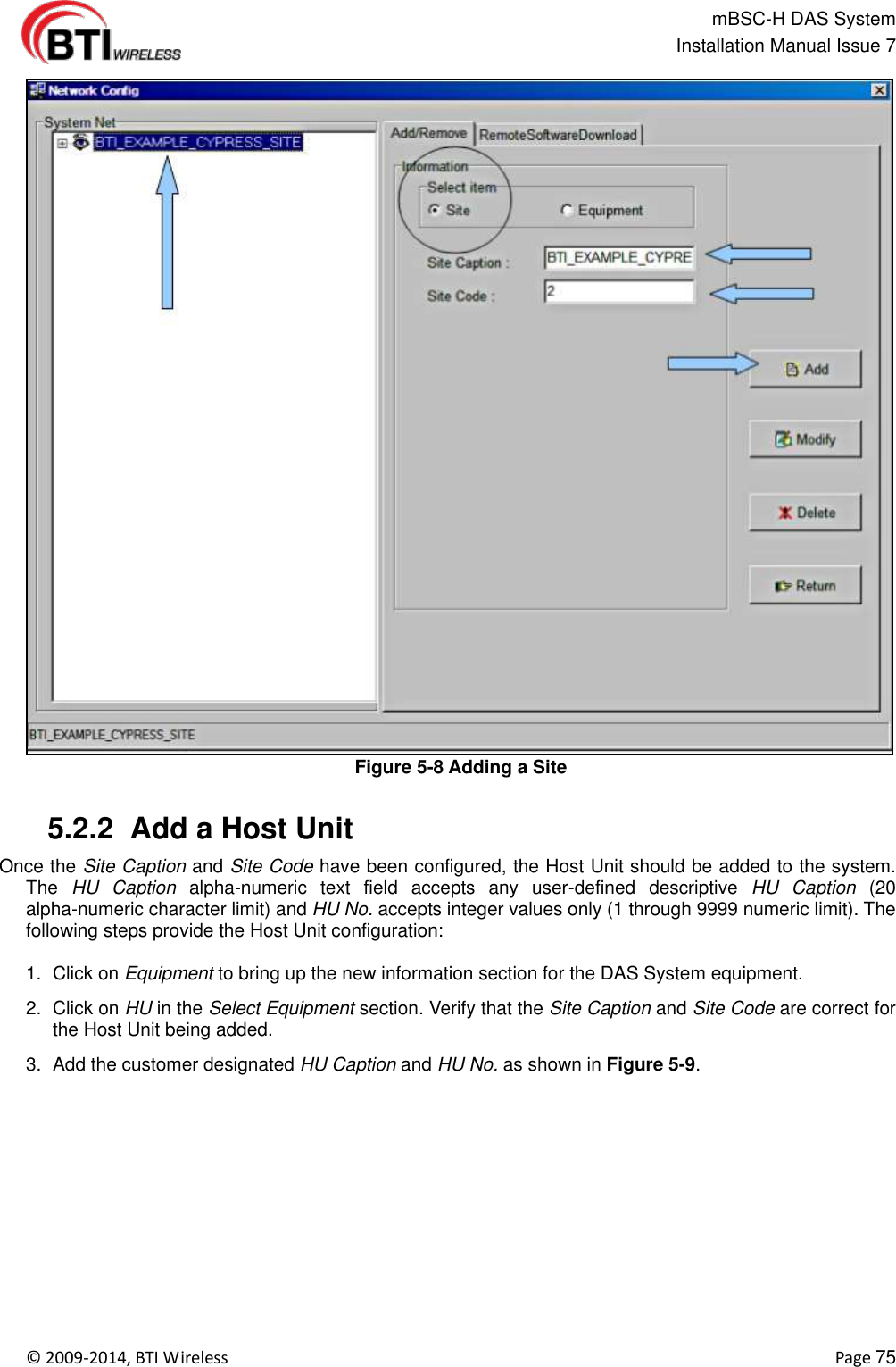
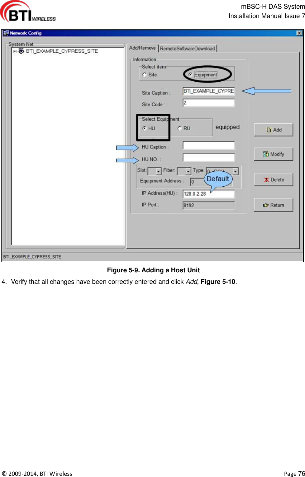
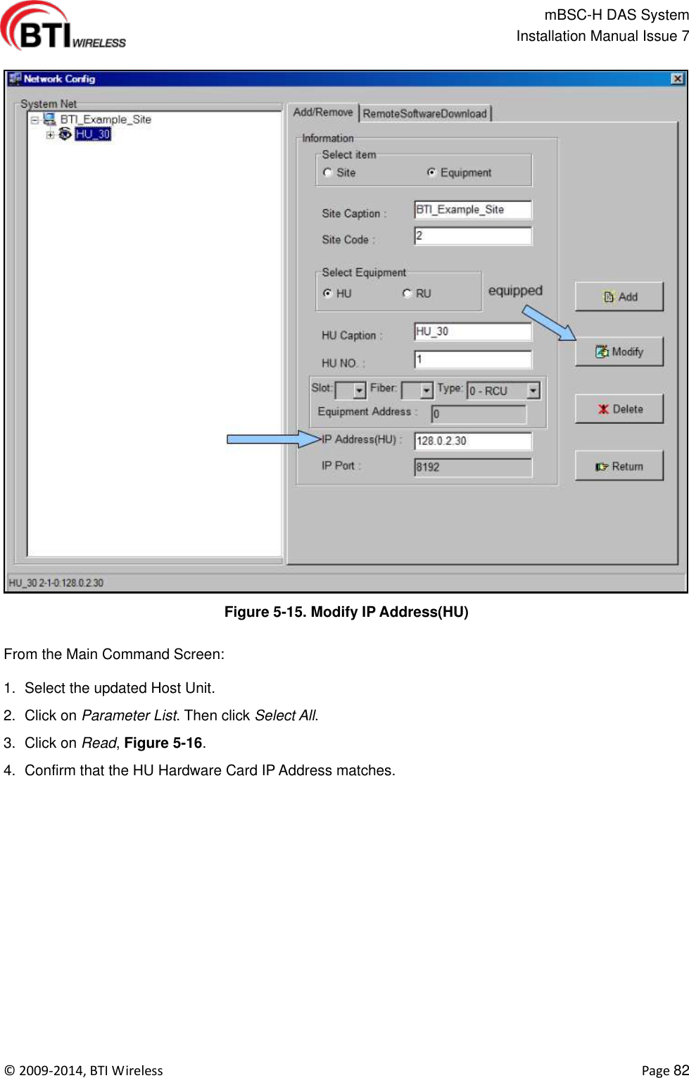
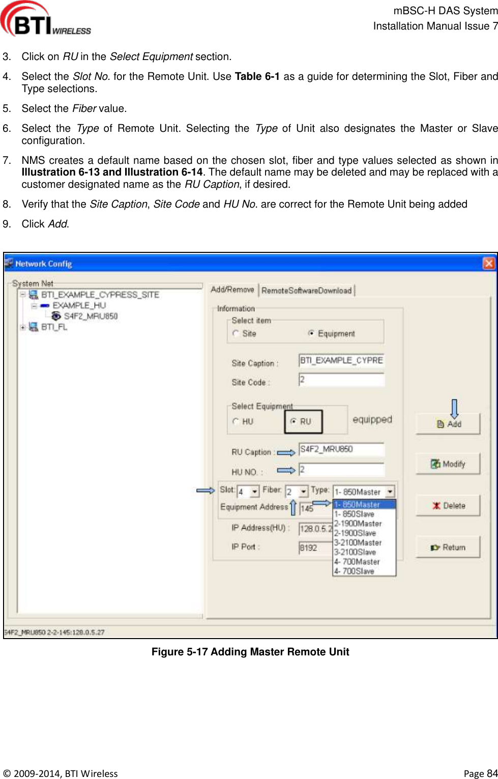
![mBSC-H DAS System Installation Manual Issue 7 © 2009-2014, BTI Wireless Page 83 Figure 5-16. Confirm IP Address Update Accepted. 5.2.5 Adding a Master and/or a Slave Remote Unit Once the Site Caption, Site Code, and Host Unit have been configured, the Master Remote Unit should be added to the system first, followed by any Slave Remote Units. The RU Caption alpha-numeric text field accepts the default RU Caption or any user-defined descriptive RU Caption (20 alpha-numeric character limit) and the RU No. field accepts integer values only (1 through 9999 numeric limit). NMS creates a default name using a combination of representative letters and numbers in the following format: S#F#_MRU###(#) [Slot#][Fiber # designation]_[MasterRU][Frequency] The example in Illustration 5-17, S4F2_MRU850 shows the default name with an M designator for Master. S#F#_SRU###(#) [Slot#][Fiber designation]_[SlaveRU][Frequency] The example in Illustration 5-18, S4F2_SRU1900 shows the default name with an S designator for Slave. 5.2.5.1 Adding a Remote Unit Use the following steps to define the Remote Unit configuration: 1. Click on the new HU in the System Net section. 2. Click on Equipment to bring up the new information section for the DAS System equipment.](https://usermanual.wiki/BTI-Wireless/DAS2100A80RUM/User-Guide-2297657-Page-83.png)