BTI Wireless DAS2100A80RUM 2.1GHz AWS Band 80W Remote Unit on BTI DAS system User Manual
Bravo Tech (Shenzhen) Co. Ltd. 2.1GHz AWS Band 80W Remote Unit on BTI DAS system Users Manual
Users Manual
mBSC-H DAS System
Installation Manual Issue 5
mBSC-H DAS SYSTEM
INSTALLATION AND
OPERATIONS MANUAL
mBSC-H DAS System
Installation Manual Issue 7
© 2009-2014, BTI Wireless Page 2
COPYRIGHT
This document serves as the System Installation Manual for the BTI mBSC-H Fiber Distributed Antenna
System (DAS) system. BTI reserves the right to change the contents without prior notice. No part of this
document may be reproduced or utilized. © 2009-2013, BTI, All Rights Reserved
REVISION HISTORY
ISSUE
NO.
DESCRIPTION
DATE
1
INITIAL DRAFT
OCT. 28, 2009
2
UPDATE SPECIFICATIONS
JAN. 18, 2010
3
UPDATE SPECIFICATIONS, INSTALLATION, AND ILLUSTRATIONS
MAY 31, 2011
4
UPDATE SPECIFICATION, INSTALLATION, MAINTENANCE, AND
ILLUSTRATIONS
FEB 22, 2012
5
UPDATE SPECIFICATION WITH THE LATEST MECHANICAL DESIGN
AUG 31, 2013
6
ADD THE MESSAGE FOR FCC WARING LABEL ON PAGE 6
APR 28, 2014
7
Change the MPE Distance to 6 meters in page 6
JUN 10, 2014

mBSC-H DAS System
Installation Manual Issue 7
© 2009-2014, BTI Wireless Page 3
Table of Contents
1 GENERAL INFORMATION ...................................................... 6
1.1 SAFETY PRECAUTIONS ............................................................................... 6
1.2 GLOSSARY AND ACRONYMS ...................................................................... 7
2 INTRODUCTION ...................................................................... 8
3 GENERAL DESCRIPTION ...................................................... 8
3.1 SYSTEM COMPONENTS DESCRIPTION ..................................................... 8
3.1.1 Host Unit ................................................................................................... 9
3.1.2 Network Management System ................................................................ 9
3.1.3 Remote Unit ............................................................................................ 11
3.2 USER INTERFACE ....................................................................................... 14
3.2.1 Host Unit Interface ................................................................................. 14
3.2.2 NMS Interface ......................................................................................... 14
3.2.3 Remote Unit Interface .......................................................................... 16
3.3 SPECIFICATIONS ........................................................................................ 18
3.3.1 Host Unit Specifications ........................................................................ 18
3.3.2 NMS Specifications .............................................................................. 18
3.3.3 Remote Unit Specification ................................................................... 19
4 INSTALLATION ...................................................................... 20
4.1 SYSTEM INSTALLATION OVERVIEW ........................................................ 20
4.2 REMOTE UNIT INSTALLATION ................................................................. 21
4.2.1 Remote Unit Installation Overview ....................................................... 21
4.2.2 Installation Hardware And Tools ........................................................... 21
4.2.3 Unpacking And Inspection .................................................................... 23
4.2.4 Mechanical Installation .......................................................................... 28
4.2.4.1 Mechanical Safety Precautions ....................................................................................... 28
4.2.4.2 Install The Mounting Panel .............................................................................................. 29
4.2.4.3 Install The Remote Unit On The Mounting Panel ............................................................ 30
4.2.4.4 Install The Shroud Cover ................................................................................................. 30
4.2.5 Electrical Installation ............................................................................. 32
4.2.5.1 Electrical Safety Precautions ........................................................................................... 32
4.2.5.2 Grounding ........................................................................................................................ 33
4.2.5.3 Route the Cables ............................................................................................................. 33
4.2.5.4 Fiber Optic Cable Connection ......................................................................................... 33
4.2.5.5 Antenna Cable Connection .............................................................................................. 34
4.2.5.6 AC Power Cable Connection ........................................................................................... 35
4.2.5.7 Slave Cable Connection .................................................................................................. 36
4.2.6 Remote Unit Installation Review ......................................................... 39

mBSC-H DAS System
Installation Manual Issue 7
© 2009-2014, BTI Wireless Page 4
4.2.6.1 Mechanical Installation Review ....................................................................................... 39
4.2.6.2 Electrical Installation Review ........................................................................................... 39
4.2.6.3 Field Status Test - Remote Unit LED Status Indicators ................................................... 39
4.2.7 Troubleshooting ..................................................................................... 40
4.3 HOST UNIT INSTALLATION ........................................................................ 41
4.3.1 Host Unit Installation Overview ............................................................ 41
4.3.2 Installation Hardware And Tools ........................................................... 41
4.3.3 Unpacking And Inspection .................................................................... 42
4.3.4 Electrical Installation ............................................................................. 43
4.3.4.1 Electrical Safety Precautions ........................................................................................... 43
4.3.4.2 Grounding ........................................................................................................................ 44
4.3.4.3 DC Power Cable Connection ........................................................................................... 48
4.3.4.4 Install the BIU and FIU modules ...................................................................................... 49
4.3.4.5 Alarm Installation ............................................................................................................. 49
4.3.4.6 Connect the BIU/FIU Modules ......................................................................................... 51
4.3.4.7 Optional Equipment Installation ....................................................................................... 52
4.3.4.8 Connect POI to BIU ......................................................................................................... 53
4.3.4.9 Connect the Fiber Optic Cable ........................................................................................ 53
4.3.5 Host Unit Installation Review .............................................................. 53
4.3.5.1 Electrical Installation Review ........................................................................................... 53
4.3.6 Troubleshooting ..................................................................................... 55
4.4 NMS INSTALLATION ................................................................................... 56
4.4.1 Installation Overview ............................................................................. 56
4.4.2 Installation Hardware and Tools ........................................................... 56
4.4.3 Unpacking And Inspection .................................................................... 57
4.4.4 Verify Server software ........................................................................... 57
4.4.5 Initial System Setup ............................................................................... 58
4.4.5.1 CD-ROM Install ................................................................................................................ 58
4.4.5.2 Launch NMS .................................................................................................................... 59
4.4.6 Initial Start-up Configuration ................................................................. 60
4.4.6.1 Modify Default Accounts .................................................................................................. 62
4.4.6.2 Set-up New User Accounts .............................................................................................. 65
4.4.6.3 Configure Software Parameters ...................................................................................... 67
4.4.7 Firmware Update .................................................................................. 68
4.4.8 Software Upgrade Installation ............................................................... 69
4.4.8.1 CD-ROM Install ................................................................................................................ 69
4.4.9 NMS Upgrade Installation Review ....................................................... 70
4.4.10 Troubleshooting ................................................................................... 72
5 mBSC DAS SYSTEM START-UP .......................................... 73
5.1 SYSTEM COMMUNICATION ....................................................................... 73
5.1.1 Establishing a Host Unit communication ............................................ 73
5.2 INITIAL NETWORK CONFIGURATION ....................................................... 76

mBSC-H DAS System
Installation Manual Issue 7
© 2009-2014, BTI Wireless Page 5
5.2.1 Add a Site ............................................................................................... 78
5.2.2 Add a Host Unit ...................................................................................... 80
5.2.3 Configuring the Host Unit Hardware Card ........................................... 82
5.2.4 Map the IP Address to the NMS Software ............................................ 86
5.2.5 Adding a Master and/or a Slave Remote Unit ...................................... 88
5.2.5.1 Adding a Remote Unit...................................................................................................... 88
5.2.5.2 Modifying or Deleting a Remote Unit ............................................................................... 91
5.2.6 Connect Host Unit to Server ................................................................. 92
5.3 MANAGING AND MONITORING ALARMS ................................................. 92
5.3.1 Alarm Manager ....................................................................................... 92
5.3.2 Configuring Standard Alarm Defaults .................................................. 93
5.3.3 System Activation Review ................................................................... 97
5.3.4 Troubleshooting ................................................................................... 98
6 Maintenance .......................................................................... 99
6.1 General ........................................................................................................ 99
6.2 Host Unit ...................................................................................................... 99
6.3 NMS 100
6.4 Remote Units ............................................................................................. 100
6.4.1 Fans....................................................................................................... 100
7 CUSTOMER SERVICE CONTACT INFORMATION ............ 101
mBSC-H DAS System
Installation Manual Issue 7
© 2009-2014, BTI Wireless Page 6
1 GENERAL INFORMATION
1.1 SAFETY PRECAUTIONS
Danger: Danger is used to indicate the presence of a hazard that will cause serious personal
injury, death or substantial property damage if the hazard is not avoided.
Warning: Warning is used to indicate the presence of a hazard that may cause serious
personal injury, possible death or substantial property damage if the hazard is not avoided.
Caution: Caution is used to indicate the presence of a hazard that will or may cause minor
personal injury or substantial property damage if the hazard is not avoided.
1. For general safety, only appropriately qualified personnel familiar with all recommended and
regulatory safety practices and installation methods may be allowed to work on this system.
2. All general and regional safety and installation regulations relating to high voltage installations,
proper use of tools and recommended individual protective equipment must be obeyed.
3. Operating instructions must be kept accessible and available for all users.
4. The network provider is responsible for implementing protective measures to avoid the health
hazards associated with radiation from the Unit antenna(s).
5. Warning: This is NOT a CONSUMER device. It is designed for installation by FCC
LICENSEES and QUALIFIED INSTALLERS. You MUST have an FCC LICENSE or
express consent of an FCC License to operate this device. Unauthorized use may result in
significant forfeiture penalties, including penalties in excess of $100,000 for each continuing
violation. Warning label messages will be also shown in online and point-of-sale marketing
materials and on outside packaging of device
6. For US and Canadian installations: FCC RF exposure compliance requires the
following antenna installation and device operation configurations be satisfied: A
separation distance of at least 6 meters must be maintained between the antenna of this device
and all persons. RF exposure compliance may need to be addressed at the time of licensing, as
required by the responsible FCC Bureau(s), including antenna co-location requirements of
1.1307(b)(3). Maximum permissible antenna gain is 17 dBi.
7. Access should be restricted to appropriately qualified personnel.
8. Operation of this Unit is restricted to the license holders of the respective frequency range.
9. Use of this equipment is only for the purpose specified by the manufacturer. Modifications or
the use of any spare parts which are not provided by or recommended by the manufacturer are
prohibited as this may cause fires, electric shock or other injuries or damage.
10. High temperatures due to power dissipation may occur, do not operate the equipment on or
near combustible materials.
11. Ascertain that the mains supply is disconnected before opening the Unit as well as
connecting or disconnecting the mains connector at the Remote Unit.
12. Observe ESD precautions. Use the available grounding system to connect ESD protection
measures before commencing maintenance work.
mBSC-H DAS System
Installation Manual Issue 7
© 2009-2014, BTI Wireless Page 7
13. This Unit complies with European standard EN60950.
14. Verify that all regulatory requirements have been met and that all system settings have been set
according to the intended use. (Please see appropriate manufacturer product information
materials.)
15. Grounding the antenna cables close to the antenna connectors of the Remote Unit for
protection against atmospheric discharge is highly suggested, even though the Remote Unit is
internally protected against over-voltage.
16. Class 1 – Laser Radiation warning: Do not look into the beam, view it directly, or
indirectly with or without optical instruments.
1.2 GLOSSARY AND ACRONYMS
The acronyms and abbreviations used in this manual are detailed in the following list.
Abbreviation
Description
AISG
Antenna Interface Standard Group
BIU
Base station Interface Unit
BTS
Base Station
CFR
Crest Factor Reduction
CL-OS
Closed-Loop Operating System
DAS
Distributed Antenna System
EDGE
Enhanced Data for GSM Evolution
FIU
Fiber Interface Unit
FIU-S
Fiber Interface Unit - Simulcast
FIU-NS
Fiber Interface Unit - Non-Simulcast
HPA
High Power Amplifier
HU
Host Unit
LMU
Location Measurement Unit
LNA
Low Noise Amplifier
mBSC
Multi-Band Multi-System Multi-Carriers
MIMO
Multi-input multi-output
MTBF
Mean Time Between Failure
NMS
Network Management System
PA
Power Amplifier
PCU
Power Controller Unit
PWM
Pulse Width Modulation
RCU
Remote Control Unit
RF
Radio Frequency
RU
Remote Unit
RX
Receive Signal
TDTD
Time delay TX diversity
TMA
Tower Mounted Amplifier
TX
Transmit Signal
UMTS
Universal Mobile Telecom System
VSWR
Vertical Standing Wave Radio
mBSC-H DAS System
Installation Manual Issue 7
© 2009-2014, BTI Wireless Page 8
2 INTRODUCTION
This document provides the installation procedures for the BTI DAS system consisting of the DAS Host
Unit, Remote Unit equipment and the Network Management System (NMS). It also provides for the initial
configuration set-up, operation procedures and the software upgrade installation process for the Network
Management System.
For Host Unit and Remote Unit installation, the reader should be familiar with the use of Distributed
Antenna Systems, power system distribution for both AC and DC, all safety guidelines and regulations,
and the required tools to accomplish the installation in a safe manner.
For NMS software installation and configuration as well as firmware update and software upgrade
installations, the reader should be familiar with server administration, software install, firmware update, and
software upgrade procedures at the administrator level.
3 GENERAL DESCRIPTION
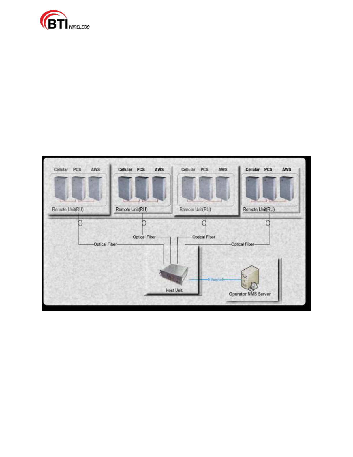
Figure 3-1. BTI DAS System
The system consists of an Indoor HU (Host Unit) and an Outdoor RU (Remote Unit) and Network
Management Software.
3.1 SYSTEM COMPONENTS DESCRIPTION
The Host Unit is designed to be mounted in a 19” rack and should only be utilized in an indoor environment
(0C - 45C) or in a place were an indoor-type environment can be provided.
The NMS (Network Management System) runs on a centralized server that provides access to the entire
network of hub sites and Remote nodes. The NMS is designed to configure, monitor, and manage all
system functionality.
mBSC-H DAS System
Installation Manual Issue 7
© 2009-2014, BTI Wireless Page 9
The Remote Units may consist of combinations of 700MHz, 850MHz, 1900MHz and 2100MHz frequencies
and are available in 20 Watt, 40 Watt or 80 Watt output configurations. Each RU is designed to support a
Single Frequency Band. For multi-frequency use, the system can be configured as multiple Master/Slave
Remote Units. Each Master Unit can support a maximum of two slave RUs with a maximum of three RUs
supported per fiber connection. The primary transport between the HU and the RU is fiber optic. The Fiber
Optic also provides the RU alarms and configuration communication between the NMS and the Remote Unit.
The downlink and uplink optical signals are duplexed so only one fiber is required.
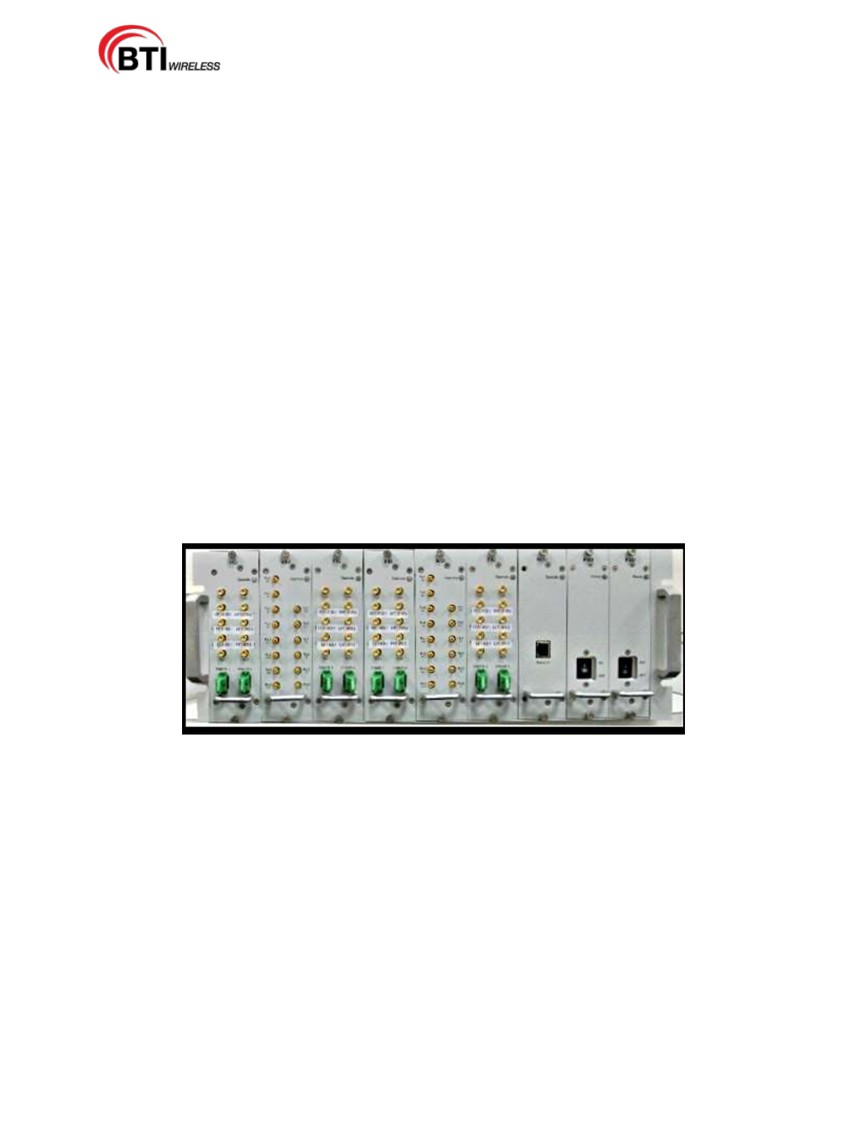
3.1.1 Host Unit
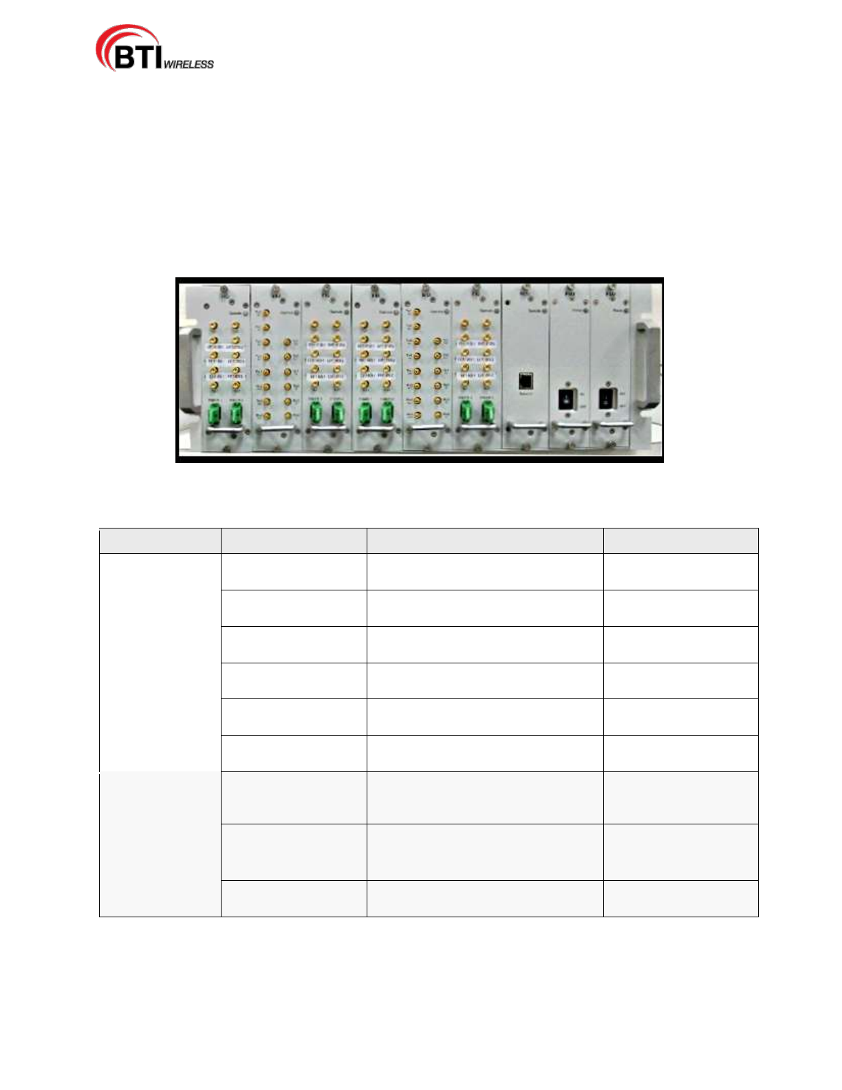
The Host Unit provides a multiple slot assembly, consisting of 9 slots numbered from left to right: 1 through
9. Slots 7 through 9 are used and specifically keyed for the Remote Control Unit (RCU) and two
redundant Power Supply Units (PSU) only. The Host Unit also houses the Base Station Interface Units
(BIU) and Fiber Interface Units (FIU), Figure 3-2. The BIU comes in Diversity (BIU-D) and Non-Diversity
(BIU-ND) and the FIU comes in Simulcast (FIU-S) and Non-Simulcast (FIU-NS) modules. The HU allows
multiple combinations of BIU and FIU modules with up to 3 band downlink and uplink RF signals per BIU
from the BTS and converts them to analog over RF for fiber transport.
The Host Unit, through interface combinations, provides the following functions:
Converts the BTS RF signal to fiber signal.
Supplies connectivity between the BTS and the Remote Unit.
Manages and monitors the system alarms and configurations.
Supports 1 to 3 Sectors system configurations.
Supports a single sector with 1:1, 2:1, 3:1 and 4:1 Simulcast configuration.
Supplies fiber connectivity to the Remote Unit with in-band message signaling.
Figure 3-2. Host Unit Multiple-Slot Assembly
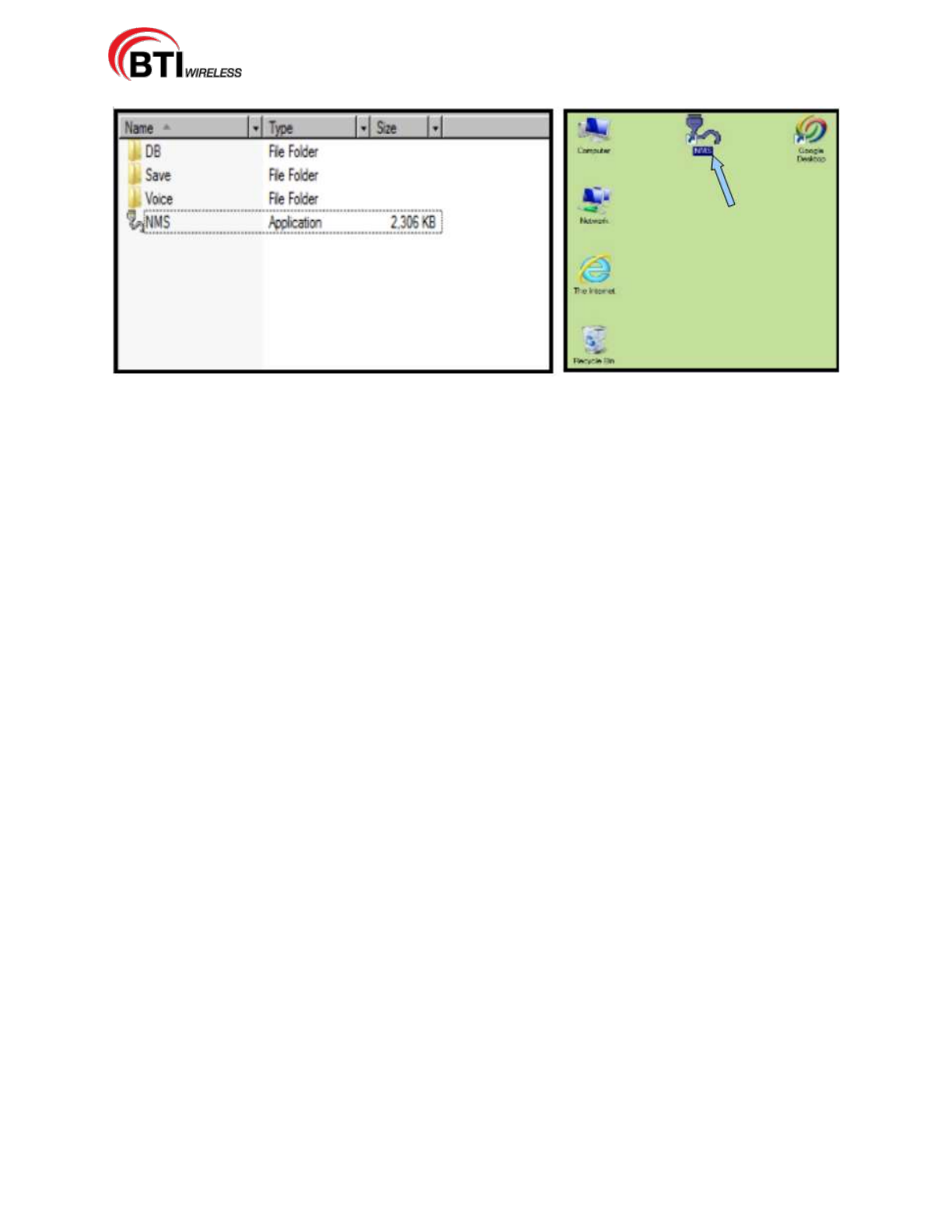
3.1.2 Network Management System
The Network Management System (NMS), shown in Figure 3-3, is a software-based Network
Management System tool that provides control and monitoring functions for the BTI mBSC DAS system.
NMS is used to provision and configure a new system for operation, set the system operating parameters,
get system alarms and status messages, and update the system firmware.
The Network Management System provides the following functions:
Manages SNMP v2 messaging to the Network Operating Center (NOC).
Provides a detailed graphic User Interface to manage, monitor and configure multiple DAS
system.
Configure multiple DAS systems custom alarms.
Provides a firmware update interface.
mBSC-H DAS System
Installation Manual Issue 7
© 2009-2014, BTI Wireless Page 10
Figure 3-3. Network Management System Software Components Folder and Desktop Icon
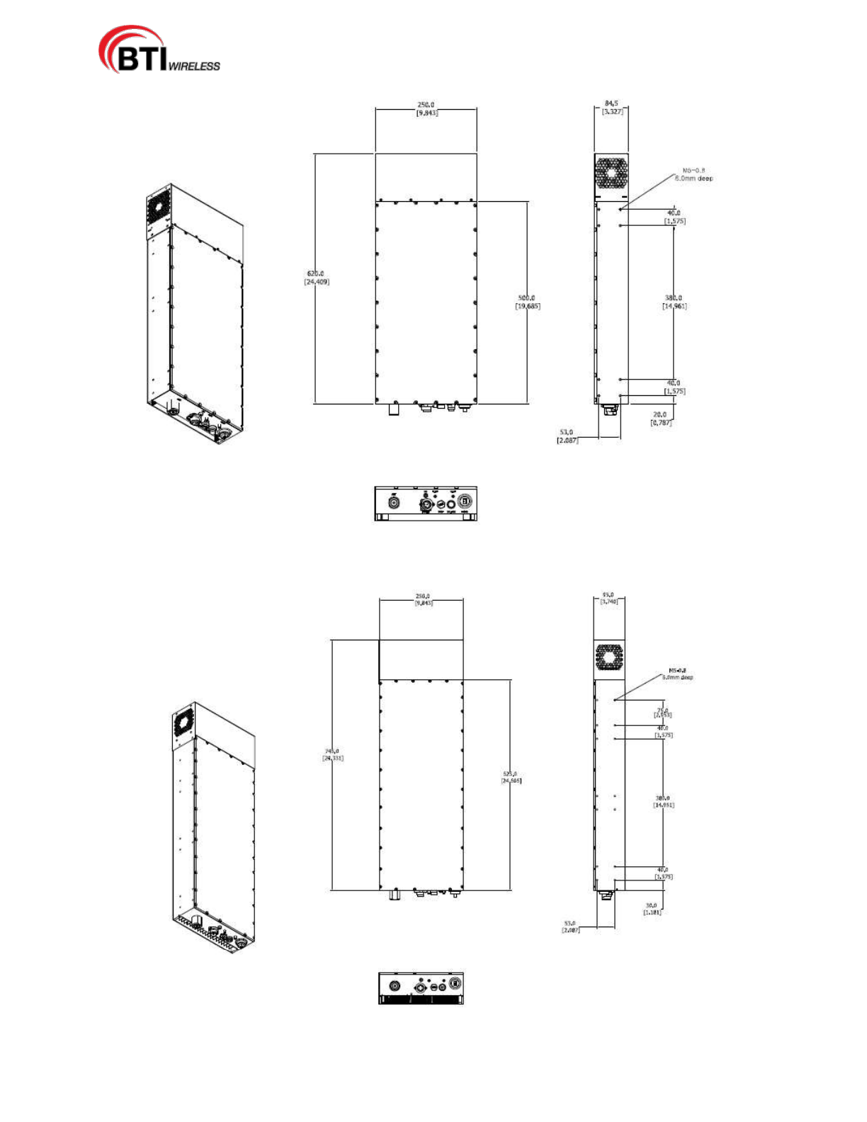
3.1.3 Remote Unit
The Single-Band Master Remote Unit, shown in Figure 3-4a, 3-4b, 3-4c and 3-4d, consists of an optical
module (O/E), a downlink power amplifier, an LNA, and duplexer. The Optical module converts the
downlink optical signal from the FIU module in the HU and splits the RF signal into 3 RUs. It also converts
the uplink RF signal to an optical signal and simultaneously sends it to the FIU module in the HU for
distribution to the BIU modules. Each optical module can support 3 RUs in any combination of different
bands.
The Single-Band Master Remote Unit provides the following functions:
Converts the forward optic signal to RF signal.
Boosts the forward RF signal from the HU to a higher power level (max output: 80W).
Amplifies the uplink signal from the antenna to improve the system receive sensitivity.
Supplies in-band messaging between the HU and RU for RU Alarms and configuration.
The Remote Unit has been designed for minimal maintenance. Maintenance recommendations include a
once yearly inspection and cleaning, if needed. A fan alarm will be generated should the fan current drop
below one third of its required current.
mBSC-H DAS System
Installation Manual Issue 7
© 2009-2014, BTI Wireless Page 11
Figure 3-4a. 20 Watt and 40 Watt Fan Cooled Remote Unit
Figure 3-4b. 80 Watt Fan Cooled Remote Unit
mBSC-H DAS System
Installation Manual Issue 7
© 2009-2014, BTI Wireless Page 12
3.2 USER INTERFACE
The user interface for each segment of the mBSC DAS System is designed to provide the most efficient
interaction, installation and ease of use for the user.
3.2.1 Host Unit Interface
Each interface module of the Host Unit, shown in Figure 3-5, is described in Table 3-1 below.
Figure 3-5. Host Unit Interface
Table 3-1. Host Unit User Interface
Module Name
Port Name
Description
Remark
FIU-S/FIU-NS
TX1, TX2
Downlink interface ports to be
connected to BIU output
RF signal
RX1, RX2
Uplink interface ports to be
connected to BIU input
RF signal
Fiber 1, Fiber 2
Fiber optic interface ports to be
connected to the RU
Optical signal
E9111, E9111-2
The RX coupling uplink signal for
LMU (TDOA location only)
RF signal
E9111, E9111-2
The RX coupling uplink signal for
LMU (TDOA Location only)
RF signal
E9111, E9111-2
The RX coupling uplink signal for
LMU (TDOA Location only)
RF signal
BIU-ND/BIU-D
TX1, TX2, TX3, TX4
Input signals from the BTS to
provide the combined downlink
signal to FIUs
RF signal
RX1, RX2, RX3, RX4
The combined uplink signal from
FIUs
RF signal
TX1 and TX2 out
Downlink RF interface to FIU
RF signal
RX1, RX2, RX3, and
RX4 out
Uplink RF interface from the FIU
RF signal
3.2.2 NMS Interface
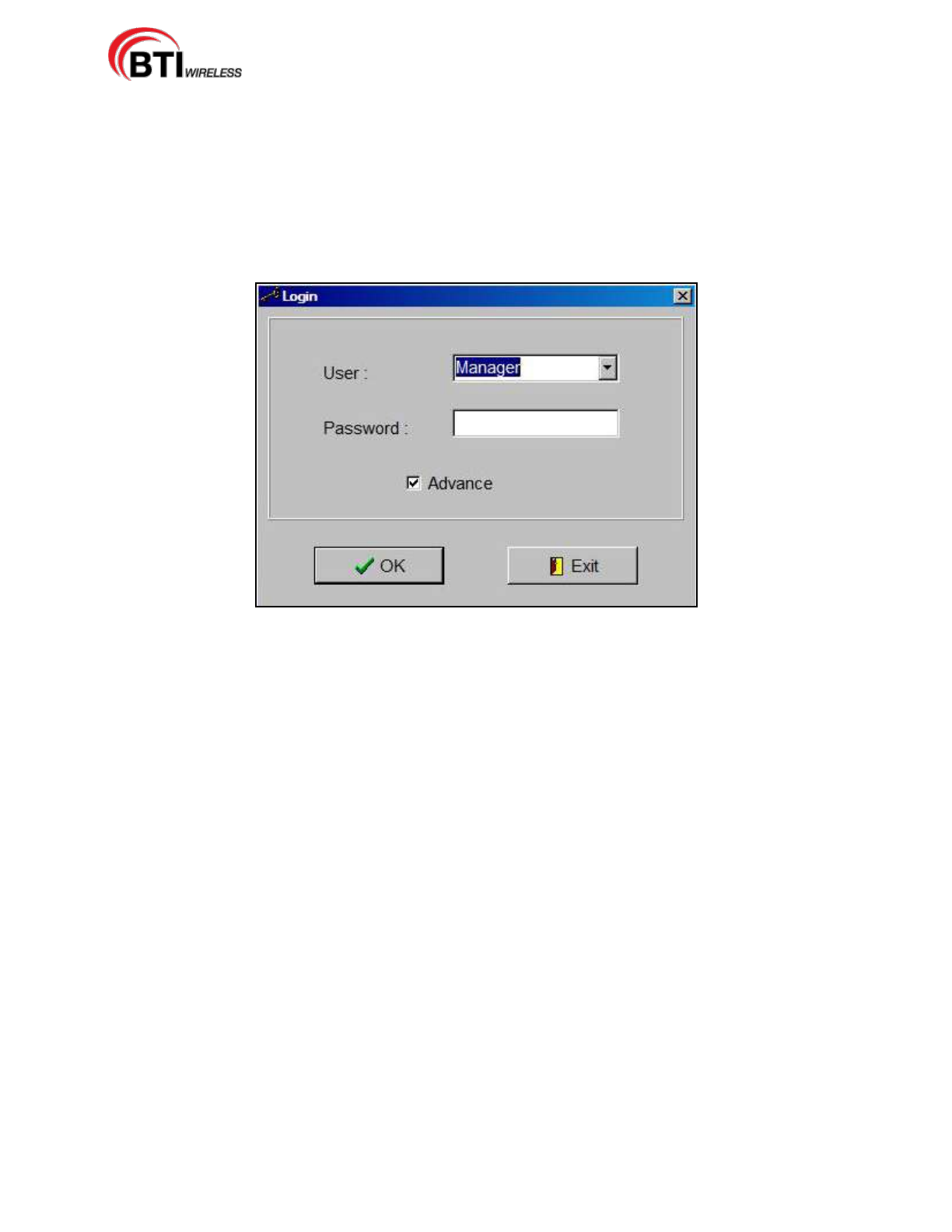
A simple login access, Figure 3-6, allows for quick access. A graphical user interface, Figure 3-7, provides
real time user access to the configuration, performance monitoring, and alarm status. The system also
mBSC-H DAS System
Installation Manual Issue 7
© 2009-2014, BTI Wireless Page 13
uses SNMPv2.0 protocol to transmit automated traps to the operator's Network Operations Center for
remote alarming and system queries. These two capabilities provide for centralized configuration and
alarm monitoring of the entire system.
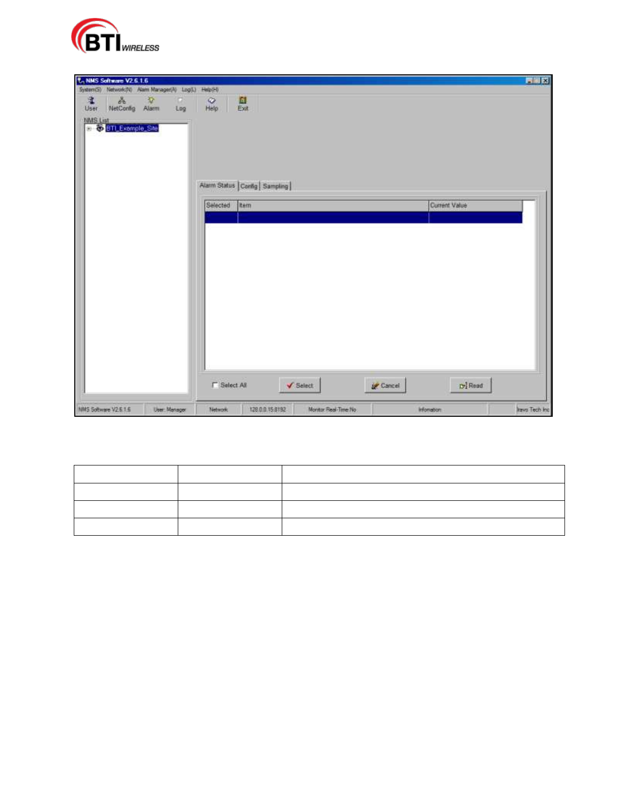
Operational parameters, such as uplink and downlink, and gain can be set through the NMS server. Status
information at each node is easily available. The customer can readily access power output, ALC status,
VSWR, PA temperature, and other basic operating parameters, The BTI NMS simplifies the configuration
of the network by providing accurate downlink power and uplink gain updates. This allows the system
operator to maximize the efficient use of field personnel when diagnosing system performance issues.
Figure 3-6. NMS Login Interface
mBSC-H DAS System
Installation Manual Issue 7
© 2009-2014, BTI Wireless Page 14
Figure 3-7. NMS Command Console
Table 3-2. Default Parameter Values
Menu
Parameter Name
Default Value
System Parameter
SNMP
No
User
Manager
Name: Manager; Password: 1; Level: Supervisor
User
User
Name: User; Password: 1; Level: Observer
3.2.3 Remote Unit Interface
The interface of the Remote Unit consists of connectors and LEDs that are located on the bottom of the
RU enclosure. The Master RU user interface points are indicated in Figure 3-8 and Table 3-3. The Slave
RU user interface points are indicated in Figure 3-9 and Table 3-4.
Remote Units are classified as either MASTER or SLAVE. Master and Slave Units have exactly the same
mechanical dimensions. Functionality is the main difference as the MASTER Remote Unit has the
connection for the fiber optic cable. For supporting multiple bands, only the MASTER Remote Unit needs
to have the fiber optic connection with the Host Unit. Other Remote Units are interfaced with SLAVE ports
for receiving RF downlink signal and sending RF uplink signal with the Master Remote Unit.
MASTER Remote Unit:
Has the Fiber Optic Cable connection with the Host Unit
Provides the RF downlink signal to the SLAVE Remote Unit through “TX_IN” or “TX_OUT” port.
Receives the RF uplink signal from the SLAVE Remote Unit “RF_IN” or “RF_OUT” port.
mBSC-H DAS System
Installation Manual Issue 7
© 2009-2014, BTI Wireless Page 15
SLAVE Remote Unit:
No Fiber Optic Cable connection with the Host Unit
Interfaces with the Master Unit for downlink and uplink signal
Unused ports (TX_OUT, RX_IN) are blocked with a cover.
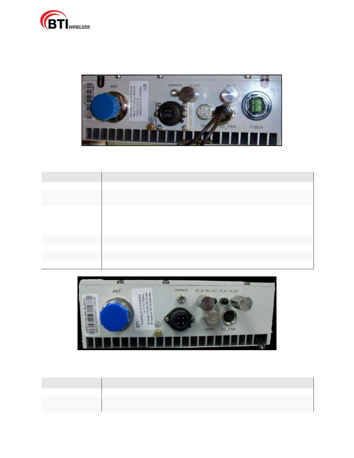
Figure 3-8. User Interface of MASTER Remote Unit
Table -3-3. Master Remote Unit User Interface
Label Name
Description
ANT
Interface port for Antenna Feed line
OPERATE
LED indicator for normal or critical fault status of the RU.
Normal: Green ON, Critical fault: Red ON
TX_Out
RF output port to provide the input signal to the Slave Remote Unit when Dual or
Triple Band application is configured.
RX_In
RF input port to provide the output signal to the Master Remote Unit when Dual
or Triple Band application is configured.
FIBER
Fiber Optic Cable interface port for combined downlink and uplink signal
POWER
Interface port for the AC 110/220V power cable
DC_FAN
Provides power to the fan
VENT
Port for the balance of pressure inside and outside of the enclosure
Figure 3-9. User Interface of SLAVE Remote Unit
Table -3-4. Slave Remote Unit User Interface
Label Name
Description
ANT
Interface port for Antenna Feed line
OPERATE
LED indicator for normal or critical fault status of the RU.
Normal: Green ON, Critical fault: Red ON
mBSC-H DAS System
Installation Manual Issue 7
© 2009-2014, BTI Wireless Page 16
TX_Out (Slave 1)
RF output port to provide the input signal to the Slave Remote Unit when Dual or
Triple Band application is configured
RX_In (Slave 2)
RF input port to provide the output signal to the Master Remote Unit when Dual
or Triple Band application is configured.
POWER
Interface port for the AC 110/220V power cable
DC_FAN
Provides power to fan
VENT
Port for the balance of pressure inside and outside of the enclosure
3.3 SPECIFICATIONS
3.3.1 Host Unit Specifications
The specifications for the Host Unit of the mBSC DAS system are listed in Table 3-5:
Table 3-5. Host Unit Specifications
Host Unit Specification
Description
Notes
System
Support Multi-Frequency bands with Multi-Air Interface
standards
(GSM / EDGE / CDMA / WCDMA / AWS / LTE)
Max No. of Plug-in
module
• 3 fixed slots for two (PSU) and a single (RCU)
• 6 module slots for BIU and FIU
PSU (Power Supply
Unit)
• -48Vdc and optional AC 110/220 DC converter
• 2 PSU are installed for redundancy
RCU (Remote
Controller Unit)
Main process board for DAS system
BIU (Base station
Interface Unit)
• Support multi-frequency bands DL and UL interface
• Support RX Diversity
• QMA connector for RF Interface
• Support 4 downlink and uplink interface ports
FIU (Fiber Interface
Unit)
• Support 2 Fiber ports per FIU
• Support Non-Simulcast or Simulcast
3.3.2 NMS Specifications
The specifications for the Network Management System (NMS) of the mBSC system are listed in Table
3-6. Table 3-6. NMS Specifications
NMS Specification
Specification
Notes
Max No. of Nodes
1080
A combination of BIU, FIU and Remote Units
SNMP based management
Yes
Real time alarm display
Yes
Display various system level
values
Yes
Voltages, RF power, etc.
Remote firmware download
Yes
Firmware update interface for DAS components.
The NMS also requires a dedicated server to connect to the RCU. The Server specifications are
Table 3-7. Server Specifications
Server
Specification
Specification
Notes
Processor
One Quad-core Intel® Xeon® 3400 series processor
mBSC-H DAS System
Installation Manual Issue 7
© 2009-2014, BTI Wireless Page 17
Server
Specification
Specification
Notes
Operating
System
Microsoft® Windows® XP Professional
Memory
4GB (4 DIMM slots) DDR3
Storage
Cabled Hard Drive Options:
2.5" SATA SSD, SAS (10K), nearline SAS (7.2K)
Maximum Internal Storage:
250G
Power
Single cabled power supply (250W)
Video Card
Matrox G200eW w/ 8MB memory
Network
Controller
One dual-port Broadcom BCM 5716
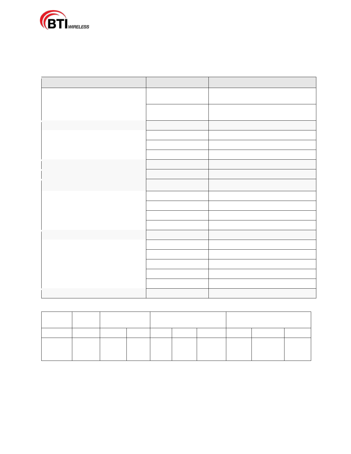
3.3.3 Remote Unit Specification
The specifications for the Remote Unit of the mBSC system are listed in Table 3-8.
Table 3-8. Remote Unit Specifications
System Specification
Downlink
Uplink
Optic Wavelength
1310/1550nm
Antenna Port
7/16 DIN female
Optical connector
E2000
Power Supply
AC 110V / 220V ± 20%
Current
< 1A @ Full power, ~220V AC input
< 2A @ Full power, ~110V AC input
Weight
varies per type
Waterproof
IP65

mBSC-H DAS System
Installation Manual Issue 7
© 2009-2014, BTI Wireless Page 18
4 INSTALLATION
4.1 SYSTEM INSTALLATION OVERVIEW
This section provides instructions for installing the mBSC DAS system in an efficient, productive and
customer friendly order. Each component of the mBSC DAS system is covered in its own installation
section as follows:
4.2.REMOTE UNIT INSTALLATION
The Remote Unit installation section provides instructions for the mechanical and electrical installation of
the mBSC Remote Unit including: mounting the Remote Unit, connecting the fiber optics cables; Antenna
feed line; and AC power cables.
The procedures in this section assume that the required Fiber Optic cables have been routed between the
Host Unit and the Single-Band RU and that the required antenna has been installed.
4.3.HOST UNIT INSTALLATION
The Host Unit installation section provides instructions for the electrical installation of the mBSC Host Unit
including verifying the DC power cable connection, connecting the network cable, the alarm connectors,
and other required connections and cables.
The procedures in this section assume that the Host Unit has been inspected, the Remote Unit(s)
installation is complete and that a dedicated IP address for the Host Unit has been designated.
4.4.NMS INSTALLATION
The Network Management System (NMS) installation section provides instructions for setting up the
pre-installed software component of the mBSC NMS. The instructions will allow a qualified user to install
the NMS software, set-up accounts, change passwords for security, and upgrade the system software and
hardware.
The procedures in this section assume that the NMS server has been received, the Host Unit is installed,
and that security software has been installed on the designated NMS computer(s).
mBSC-H DAS System
Installation Manual Issue 7
© 2009-2014, BTI Wireless Page 19
4.2 REMOTE UNIT INSTALLATION
Danger: Wet conditions increase the potential for receiving an electrical shock when
installing or using electrical power equipment. To avoid electrical shock, never install or use
the electrical equipment in a wet location.
Danger: Do not look into the end of the fiber optic cables. Exposure to laser radiation may
result. Do not assume that the laser power is turned off or that the fiber optic cable is
disconnected at the other end.
Danger: Use extreme caution when working with high voltage AC power. Ensure all power is
disconnected before working on power circuit.
Caution: Always make sure there is sufficient cable length to permit the routing of the fiber
optic cables to prevent the cable damage. The optic cables may be damaged if bent or coiled
too tightly.
4.2.1 Remote Unit Installation Overview
The installation of the Remote Unit, both single enclosure and multi-enclosure, consists of the following
steps:
Table 4-1. Remote Unit Installation Overview
Step
Operation Type
Operation Action
1
MECHANICAL
INSTALL THE RU MOUNTING PANEL TO THE TOWER
2
MECHANICAL
VERIFY THAT THE SIDE MOUNTING BRACKETS ARE
SECURELY ATTACHED TO THE REMOTE UNIT
3
MECHANICAL
INSTALL THE MASTER REMOTE UNIT ON THE MOUNTING
PANEL
4
MECHANICAL
MOUNT THE SHROUD COVER OVER THE ENCLOSURE AND
SECURE IT
5
INSTALLATION
REVIEW
CONFIRM THE MECHANICAL INSTALLATION USING TABLE 4-4
MECHANICAL INSTALLATION CHECKLIST
6
ELECTRICAL
GROUND THE UNIT
7
ELECTRICAL
ROUTE THE CABLES TO BE CONNECTED
8
ELECTRICAL
CONNECT THE FIBER OPTIC CABLES
9
ELECTRICAL
CONNECT THE ANTENNA FEED LINE
10
ELECTRICAL
INSTALL THE AC POWER CABLE
11
ELECTRICAL
CONNECT ANY SLAVE REMOTE UNIT TO THE MASTER
REMOTE UNIT
12
INSTALLATION
REVIEW
CONFIRM THE ELECTRICAL INSTALLATION USING TABLE 4-5
ELECTRICAL INSTALLATION CHECKLIST
13
FIELD STATUS TEST
CHECK THE REMOTE UNIT LED STATUS INDICATORS USING
TABLE 4-6 RU LED STATUS INDICATOR AND THE
TROUBLESHOOTING GUIDE
4.2.2 Installation Hardware And Tools
The Remote Units are shipped with the standard mounting hardware required for a BTI pole-mount
mBSC-H DAS System
Installation Manual Issue 7
© 2009-2014, BTI Wireless Page 20
installation. Table 4-2 lists the mounting hardware provided by the manufacturer for a standard BTI pole
mount installation kit. Additional hardware may be needed, depending on the site requirements, and may
be ordered through Customer Service (Section 6).
Table 4-2. Single-Band RU Mounting Hardware and Fasteners
for a standard BTI pole mount installation kit
Hardware and Fasteners
Quantity
Rec'd
MOUNTING PANEL
(Configurable)
1
I-BEAM or U-BEAM/CHANNEL
MOUNTING BRACKETS
2
SHROUD COVER
1
M5 SCREW
8
M5 LOCK WASHER
8
M5 FLAT WASHER
8
M6 SCREW
8
M6 LOCK WASHER
8
M6 FLAT WASHER
8
M8 SCREW
8
M8 LOCK WASHER
8
M8 FLAT WASHER
8
M12 SCREW
4
M12 LOCK WASHER
4
M12 FLAT WASHER
4
JUNCTION BOX
1
RF CABLE (Designated Slave Unit)
2
FIBER OPTIC COWL
1
POWER CABLE (10 FEET)
1
FAN CONNECTOR (OPTIONAL)
1
Table 4-3. Specified Hardware Torque
Type
Screws
Hex Nuts
Spacers
Spring/Lock Washers
Spacers
Flat Washers
Thread
M5
M8
M12
M5
M8
M12
M5
M8
M12
Specified
Torques
(lb. - ft.)
2
12
40
2
12
40
2
12
40
The following is a list of tools and any additional materials required for mounting every Single-Band
Remote Unit configuration:
DIN male connectors
Tool kit for attaching DIN connectors to coaxial cable
Tools for installing exterior AC circuit
Tools for securing M5 screw
mBSC-H DAS System
Installation Manual Issue 7
© 2009-2014, BTI Wireless Page 21
Wire cutters
Wire Stripper
Open End Wrench 1.25 inch/33mm (used for DIN connector)
Hex Wrench 5mm (M6 screw)
SAE Wrench 5/16 inch/8mm (the Slave Remote Unit connectors)
4.2.3 Unpacking And Inspection
This section provides the instruction for receiving the equipment shipment, verifying all parts have been
received and checking that no damage has occurred during transportation. The Remote Unit includes the
following items:
Remote Unit(s)
Hardware and Fasteners described in Table 4-2, Section 4.2.2
Use the following procedure to unpack and inspect the Remote Unit and accessories:
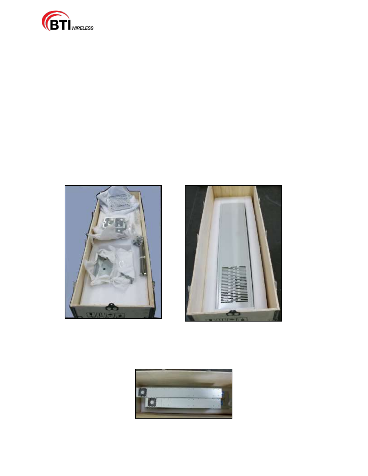
1. Open the shipping container, Figure 4-1 and carefully remove any accessories from the protective
packing material, Figure 4-2.
Figure 4-1. Open the Shipping Container Figure 4-2. Remove Accessories
2. Remove the Shroud from the Remote Units(s), Figure 4-3.
Figure 4-3. Remove the Shroud
mBSC-H DAS System
Installation Manual Issue 7
© 2009-2014, BTI Wireless Page 22
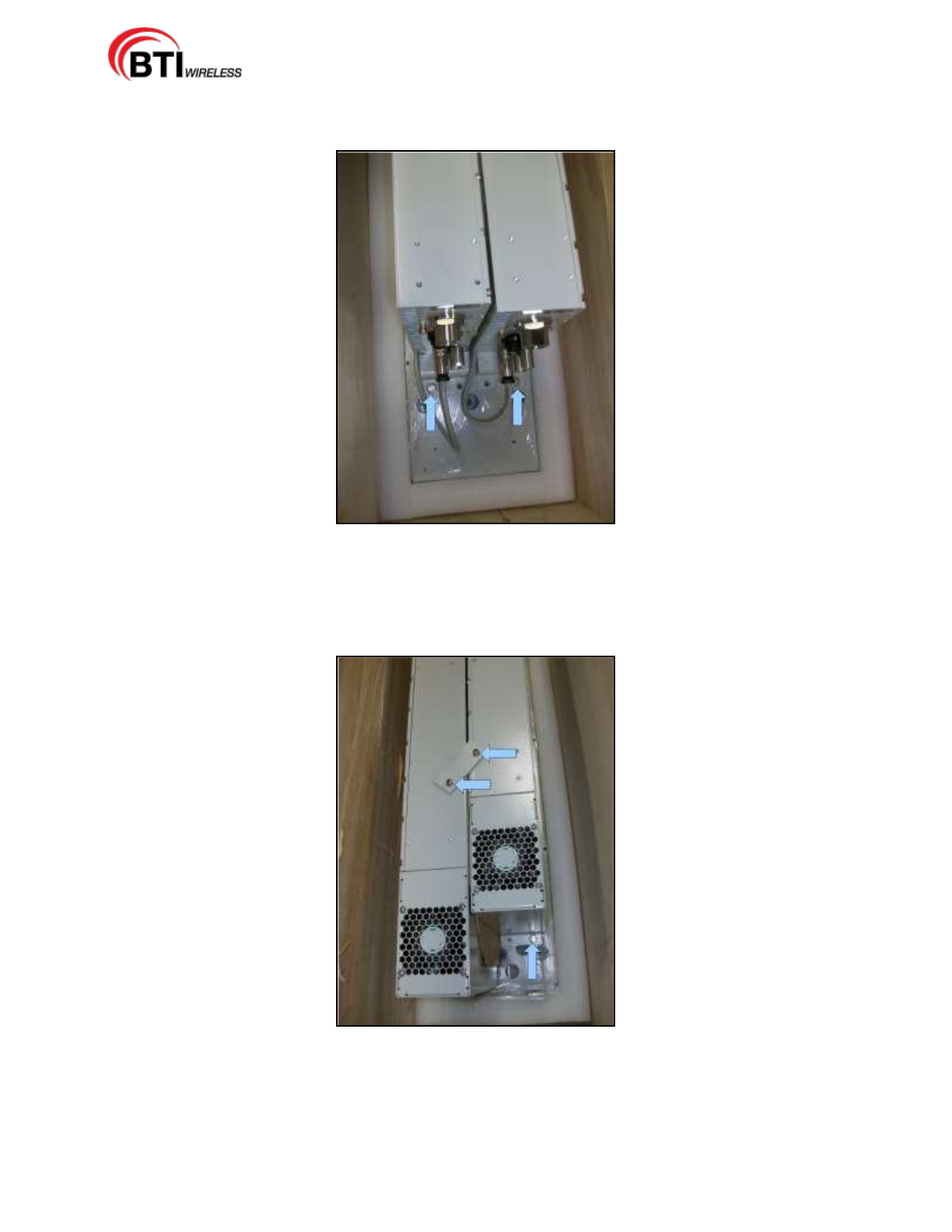
3. Begin removing the Remote Unit(s) from the Mounting Panel by unscrewing the two (2) M8 fasteners
at the bottom bracket Interface end of the Remote Unit(s), Figure 4-4.
Figure 4-4. Remove the two M8 Fasteners
4. Remove the single (1) M8 fastener from the top bracket Fan end of the Remote Units and then remove
the two (2) M5 fasteners from the metal shipping bracket and discard the metal shipping bracket,
Figure 4-5.
Figure 4-5. Remove the M8 Fastener and the two M5 Fasteners
5. Remove the Remote Unit(s) from the shipping crate.
6. Unpack the Mounting Panel from the crate.

mBSC-H DAS System
Installation Manual Issue 7
© 2009-2014, BTI Wireless Page 23
7. Verify receipt of hardware and fasteners using Table 4-2
8. Check each Remote Unit and accessories for broken or missing parts. If there is any damage or
missing parts, contact BTI (Section 6) for an RMA and to reorder parts, if any replacement parts are
required.
NOTE: Check particularly for any damage to the power connection, the fins/fans,
and the fiber optic cable connection on the Remote Unit Interface.
mBSC-H DAS System
Installation Manual Issue 7
© 2009-2014, BTI Wireless Page 24
4.2.4 Mechanical Installation
4.2.4.1 Mechanical Safety Precautions
Please read the general Safety Precautions contained in Section 1.2 Safety Precautions
1. Follow the procedures provided by the manufacturer when installing the Remote Unit. Do not
install the Unit in a place or in a manner that does not meet the manufacturer's provided
specifications.
2. Use the mounting hardware supplied by the manufacturer. If non-standard mounting hardware
is used, it must meet the requirements for mounting the Unit as specified by the manufacturer.
NOTE: It is important that specified load limits for the Unit are not exceeded as this may
void the warranty.
3. Safety measures for lifting heavy materials should be followed to prevent injury.
4. High temperatures may occur due to power dissipation. Please follow the specifications for
proper Remote Unit ventilation as indicated by the manufacturer.
5. Check that the mains supply is disconnected, before connecting or disconnecting the main
power connector at the Remote Unit.
6. Do not block airflow ventilation outlets during installation or Remote Unit(s) may sustain
critical damage.
mBSC-H DAS System
Installation Manual Issue 7
© 2009-2014, BTI Wireless Page 25
4.2.4.2 Install The Mounting Panel
Use the following procedure to install the mounting panel on the pole:
1. Take one M12 screw and insert it loosely in one of the two top holes in the panel. Place the mounting
panel against the pole as shown in Figure 4-6.
2. Place one of the two I-Beam or U-Beam brackets on the back side of the pole so that it aligns with the
M12 screw.
3. Hand tighten the screw to hold it in place
4. Place the second M12 screw in the next hole at the top of the panel and loosely fasten the screw as
well. Continue until all four screws are in place as shown in Figure 4-7.
5. Use a wrench to securely fasten the screws through both panel and brackets until the panel is securely
attached to the pole.
Figure 4-6. Attach the Mounting Panel and Bracket to a Pole
mBSC-H DAS System
Installation Manual Issue 7
© 2009-2014, BTI Wireless Page 26
Figure 4-7. The Mounting Panel secured tightly to a Pole
4.2.4.3 Install The Remote Unit On The Mounting Panel
Use the following procedure to install the RU on the mounting Panel.
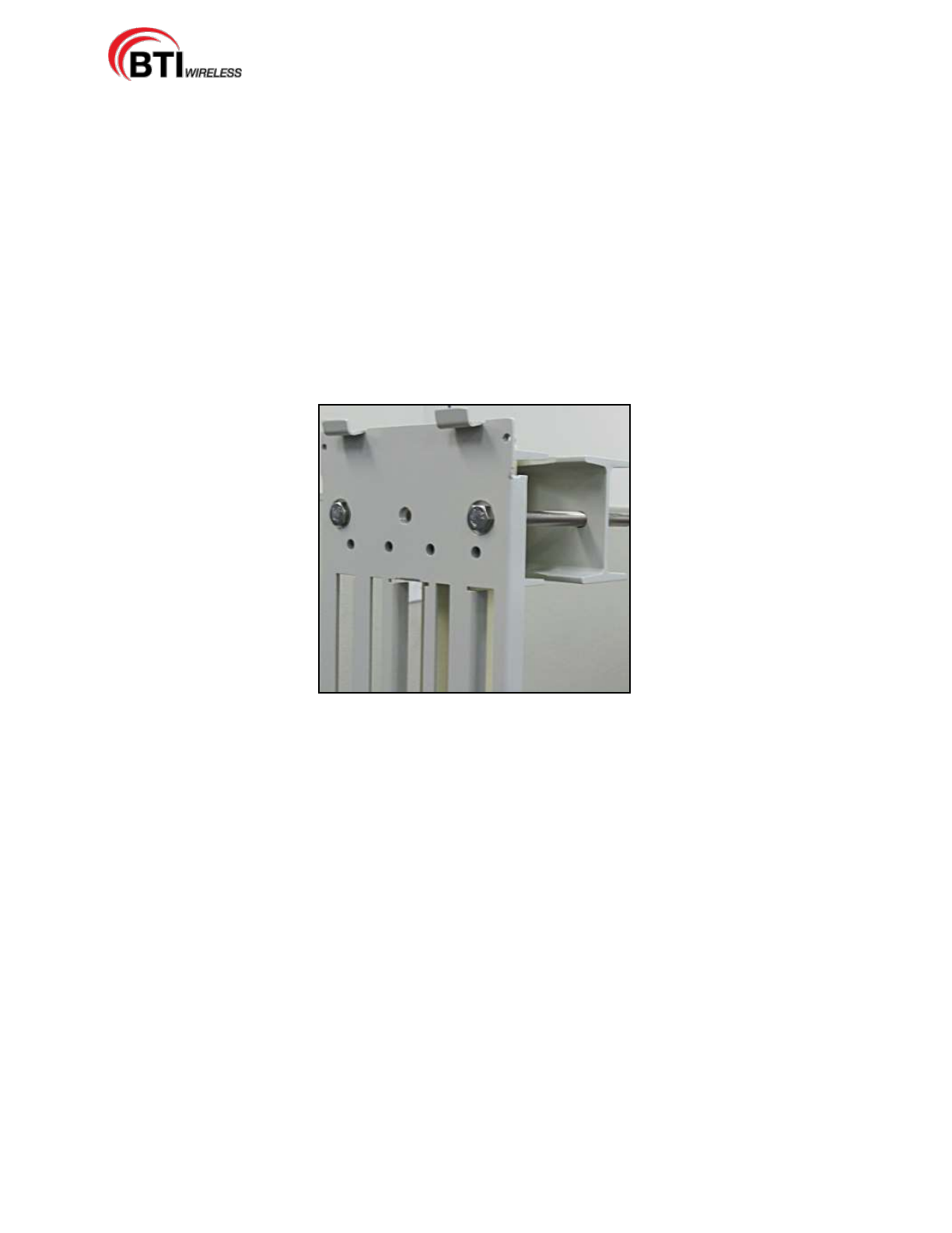
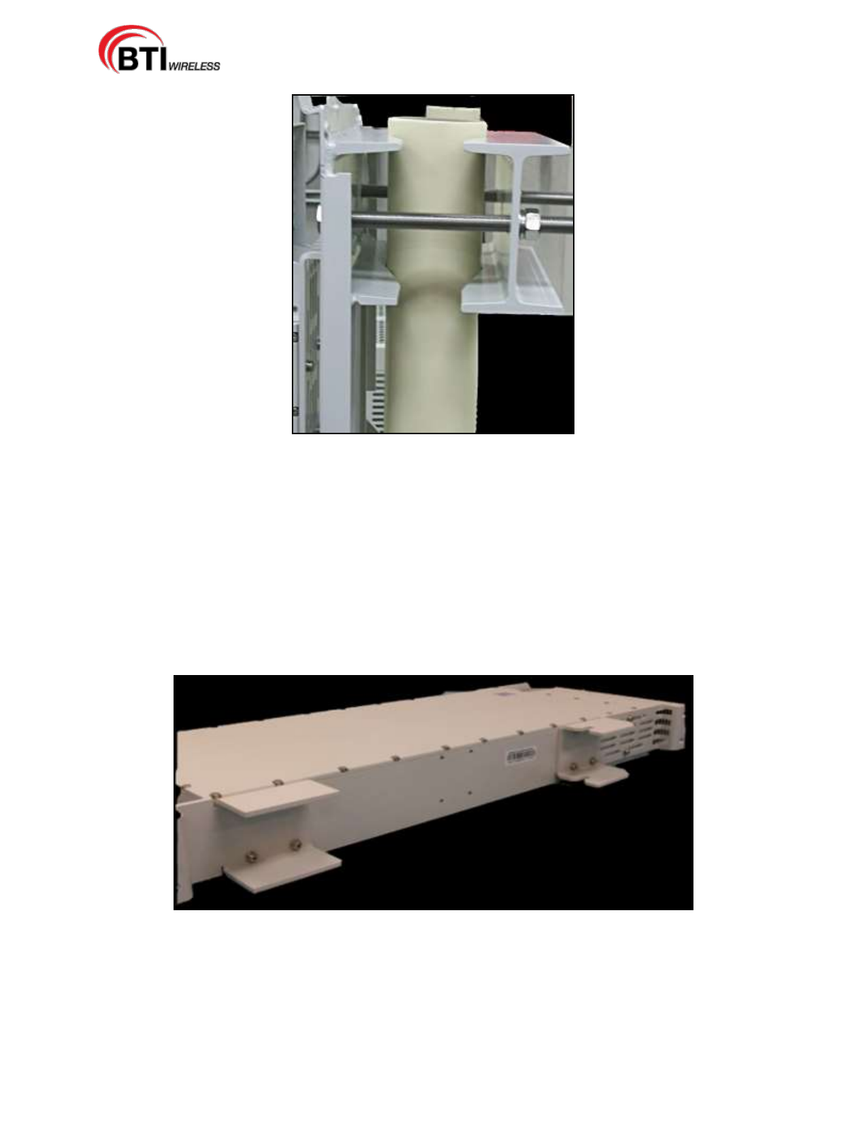
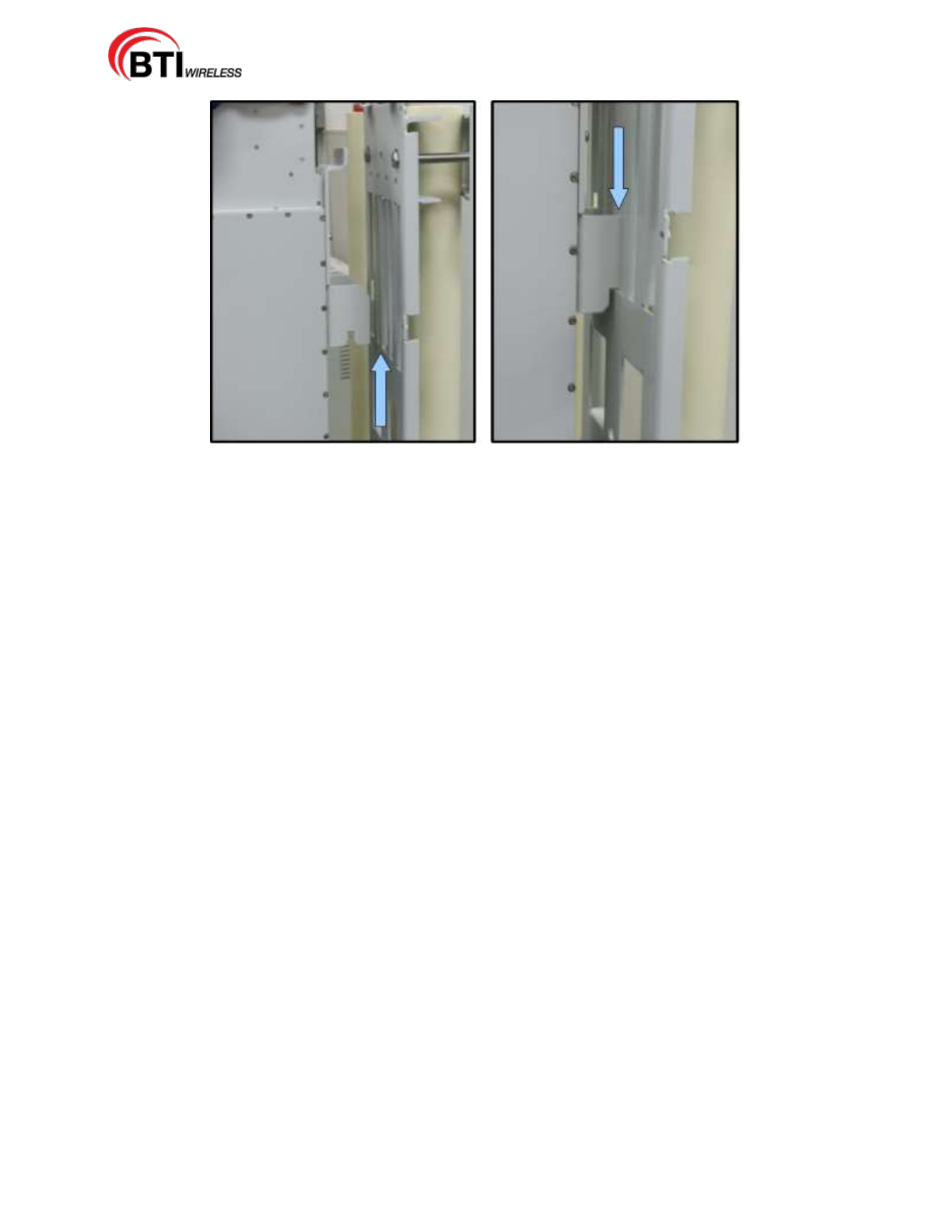
1. Verify that the attached side mounting brackets, as shown in Figure 4-8 are secure.
2. Grasp the Remote Unit at the top and bottom of the casing and carefully slide the top two hooks onto
the mounting panel, Figure 4-9, followed by the lower hooks and allow the Unit to slide down into place.
3. After hanging the enclosure on the mounting panel, use the M8 screws, lock and flat washers to secure
the rear mounting bracket (top and bottom) so the RU does not move.
Figure 4-8. The Side Mounting Bracket to the Mounting Panel
mBSC-H DAS System
Installation Manual Issue 7
© 2009-2014, BTI Wireless Page 27
Figure 4-9. Secure Enclosure To the Side Mounting Bracket
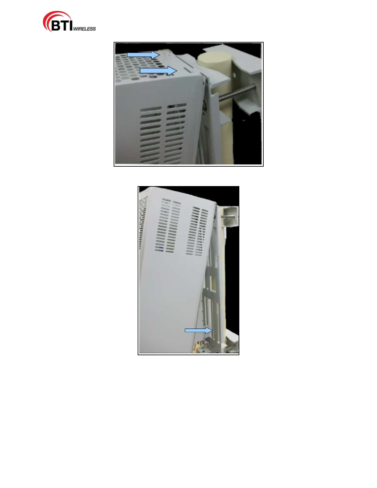
4.2.4.4 Install The Shroud Cover
The Remote Unit has a Shroud cover for thermal protection.
Use the following procedure to install the Shroud cover on the enclosure:
1. Line up the slots at the top of the Shroud cover to the tabs at the top of the mounting panel as shown in
Figure 4-10.
2. Gently lower the slots over the tabs and slide the cover down. The cover will be at an angle, Figure
4-11.
3. Lay the cover flush against the mounting bracket, then carefully, place the M5 screw through the middle
hole, aligning it to the hole on the bracket. Loosely fasten the screw. Working on the opposite side,
again place an M5 screw through the middle hole and loosely fasten the screw.
4. Loosely fasten the remaining M5 screws to all four corners of the cover and then tighten all the screws
securely.
mBSC-H DAS System
Installation Manual Issue 7
© 2009-2014, BTI Wireless Page 28
Figure 4-10. Install the Shroud Cover to the RU
Figure 4-11. Secure Shroud Cover to the mounting panel
mBSC-H DAS System
Installation Manual Issue 7
© 2009-2014, BTI Wireless Page 29
4.2.5 Electrical Installation
4.2.5.1 Electrical Safety Precautions
Please read the general Safety Precautions presented in Section 1.2 Safety Precautions
1. This Unit uses high voltages. Follow the instructions for installation provided in this
manual to prevent serious accidents including loss of life, severe personal injury or
extensive property damage.
2. The Unit must be grounded before connecting any power supply. Grounding is a
required precautionary measure. Grounding instructions are provided and should be
followed for safety.
3. The Unit is internally protected against over-voltage, but in areas with strong and frequent
lightning strikes additional lightning protection is strongly recommended. Grounding the
antenna cables close to the antenna connectors will help prevent damage from atmospheric
discharge.
4. Verify that there is a suitable circuit breaker and an over-current limiting device connected
between the mains and the Remote Unit.
5. Check that the mains supply is disconnected, before connecting or disconnecting the main
power connector at the Remote Unit.
6. An easily reached emergency disconnect device should be provided in the mains circuit if the
power feeds to the Remote Unit(s) are not within close reach.
7. The Remote Unit should be installed in close proximity to a power source with a circuit
breaker to ensure safe installation and for ease of power connectivity.
8. Electrical and electronic components can be destroyed by incorrectly wired connections.
9. Cable connector materials must meet manufacturer specifications to avoid corrosion at the
connectors.
10. Check cable connections to ensure that water cannot penetrate the Unit.
11. Caution should be used when attaching the antenna. Hand tightening should be sufficient for
connecting the antenna during installation. Manufacturer's recommendation for torque
specification should be used during installation. Use the appropriate tool to complete the
Antenna installation, but do not use tools, such as pliers, as they may cause damage to the
Remote Unit.
12. A voltage limiting device is strongly recommended for electrical networks that often produce
spikes.
13. Compliance with the surge requirement of EN 61000-4-5 (fine protection) has been met by this
Unit. Installing additional external surge protection, depending on the individual application,
via local supply connection and/or coarse protection is recommended to avoid damage
caused by electrical surges.
mBSC-H DAS System
Installation Manual Issue 7
© 2009-2014, BTI Wireless Page 30
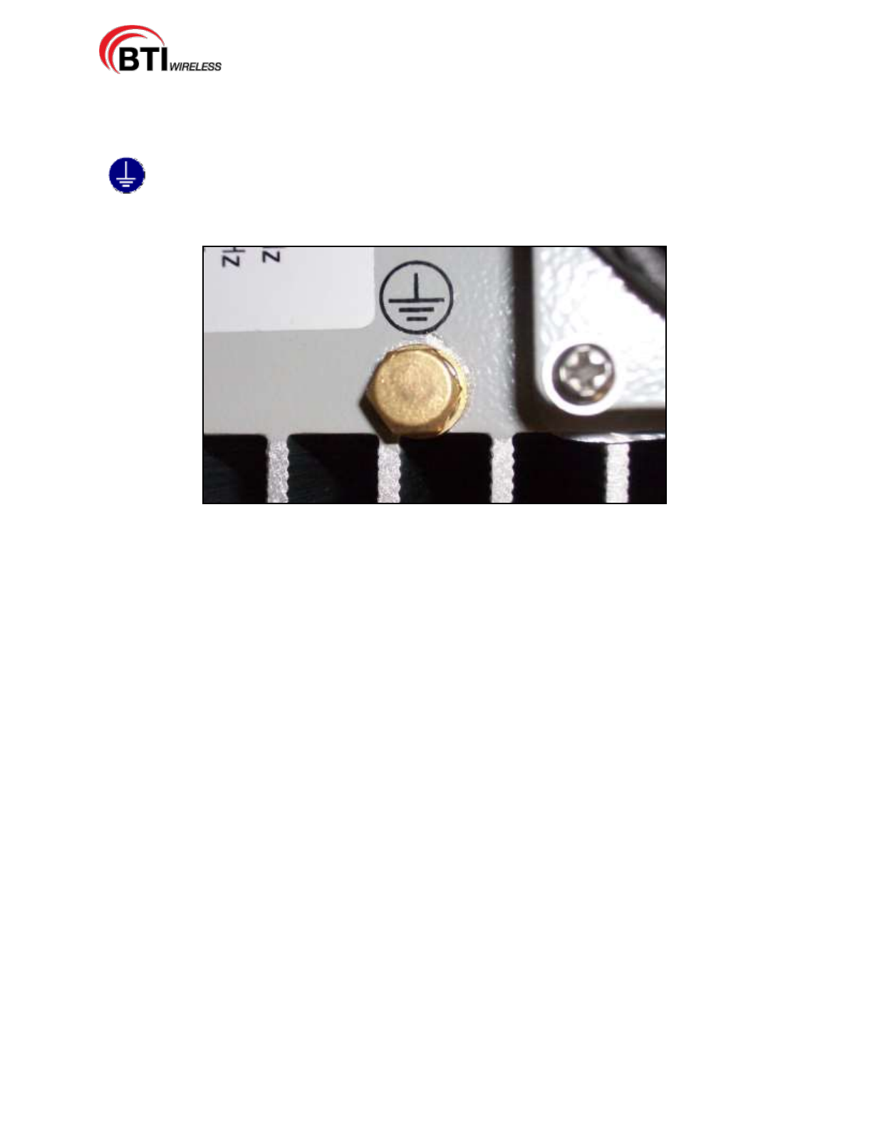
4.2.5.2 Grounding
The Unit must be grounded and the integrity of the protective earth must be ensured. Connect an
earth-bonding cable to the provided grounding connection on the equipment. Do not connect any
additional external devices to the grounding connection.
Figure 4-12. Grounding Connection
1. Uncover the RU interface by removing the Vandalism Protective Shield from the bottom of the Shroud
Cover.
2. Loosen the hex nut located on the grounding connection as shown in Figure 4-12.
3. Connect the earth-bonding cable between the two lock and flat washers.
4. Tighten the hex nut, making sure the cable is securely connected before moving to the next phase of
the installation.
4.2.5.3 Route the Cables
Prepare and route all cables according to standard field installation procedures.
The mains cable and mains plug is used as a disconnect device. For PLUGGABLE EQUIPMENT, the
socket-outlet shall be installed near the equipment and shall be easily accessible.
Care should be taken to prevent wear or field damage to cables during install. Particular attention should
be paid to the Fiber Optics Cable as damage may occur if cable is tightly coiled or bent.
The remote unit is connected to a external antenna or dish, and the antenna ports (mounted on the
rear side of the EUT) is considered a Cable Distribution System circuit (CDS). Circuits for connection to the
CDS are classified as TNV-1.
4.2.5.4 Fiber Optic Cable Connection
One fiber optic cable must be routed from an external splice enclosure or fiber access terminal to the
Master Remote Unit enclosure. The RU is equipped so only one cable is required per Master Remote Unit
for the optic port. A hardened optical E2000 connector is used for the optic port.
mBSC-H DAS System
Installation Manual Issue 7
© 2009-2014, BTI Wireless Page 31
Warning: Do not look into the end of the fiber optic cable. Do not look directly into the optical
transmitter of any Unit or exposure to laser radiation may result. An optical power meter
should be used to check the active fibers.
Use the following procedure to connect the fiber optic cable:
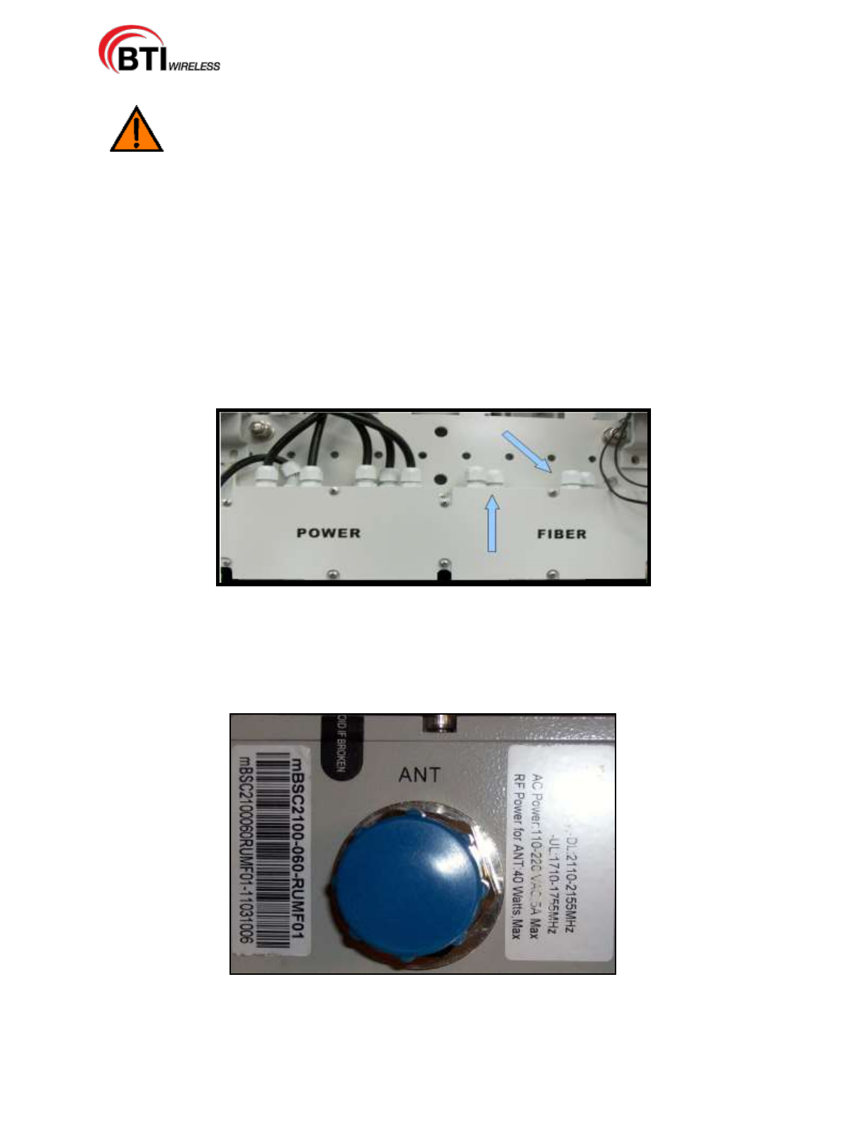
1. Connect or splice the drop Fiber cable to the outside plant cable. Verify that there is sufficient cable
length to reach from the splice enclosure or fiber access terminal (not provided) to the bottom of the
Master Remote Unit
2. Route the free end of the drop cable to the enclosure through the junction box as shown in Figure 4-13.
3. Leave sufficient slack to allow the cable to be connected and disconnected from the enclosure fiber
optic port without bending or crimping the fiber optic cable.
4. Remove the cap from the interface port labeled "FIBER". Connect the fiber optic cable to the port on the
bottom of the enclosure.
Figure 4-13. Junction Box
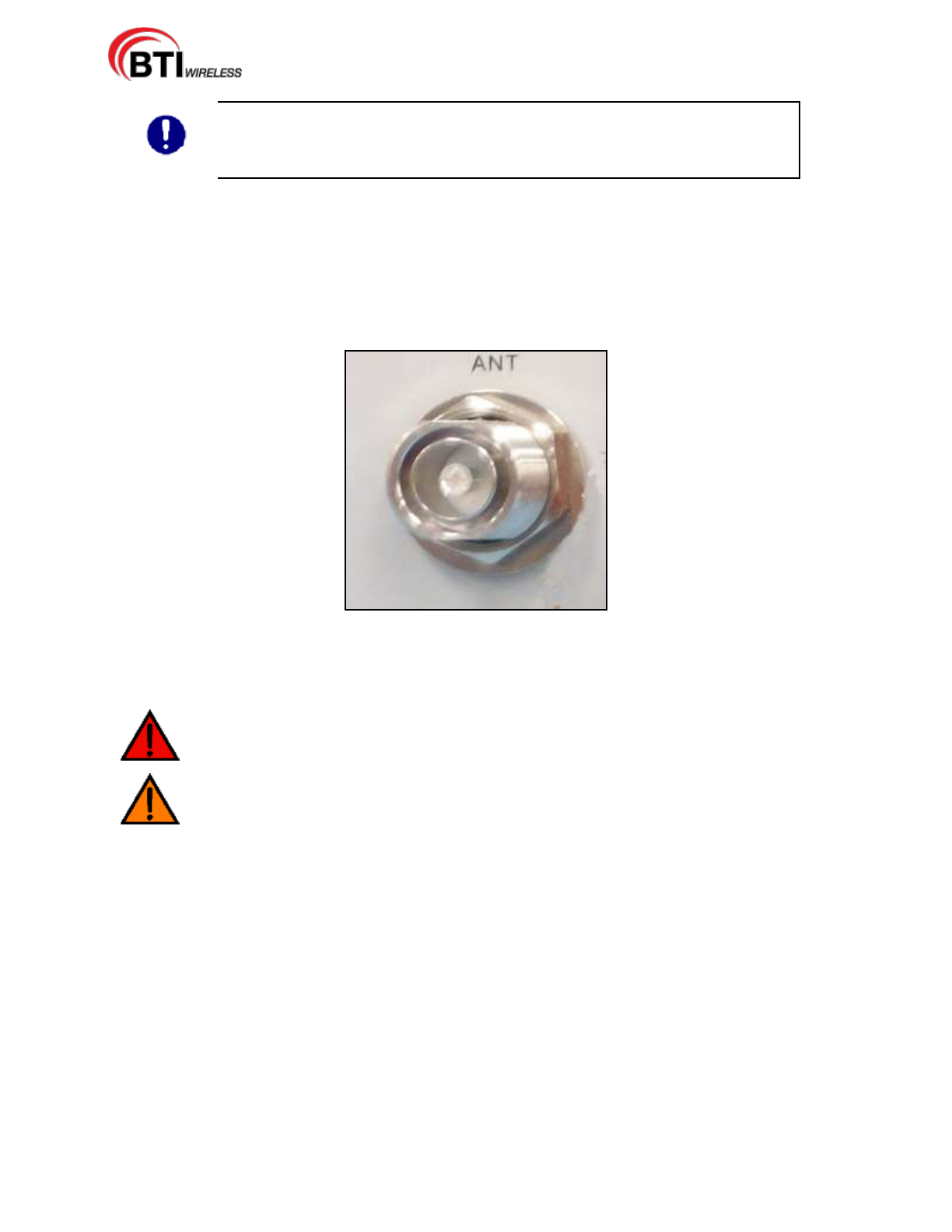
4.2.5.5 Antenna Cable Connection
The antenna feed line(s) must be routed from the antenna to each Remote Unit. The cable must have the
appropriate antenna connector termination to connect to the RU antenna port (ANT), shown in Figure
4-14.
Figure 4-14. Antenna port
Use the following procedure to install the antenna cable:
mBSC-H DAS System
Installation Manual Issue 7
© 2009-2014, BTI Wireless Page 32
NOTE: When using multiple RU enclosures to support more than one RF band,
each RU is supporting a different frequency. When routing the coaxial antenna
cable, it is critical that the appropriate frequency band cable be connected to the
same frequency type RU.
1. Remove the dust cap from the DIN female connector located on the bottom of the enclosure. The port
is labeled with “ANT”.
2. Route the coaxial antenna cables from the antenna to the bottom of the enclosures.
3. Cut the antenna cable to the required length and terminate with the appropriate connector.
4. Connect the antenna cable to the antenna port labeled with “ANT”, Figure 4-15.
Figure 4-15. DIN Female Connector
4.2.5.6 AC Power Cable Connection
Danger: Use extreme caution when working with high voltage AC power. Ensure all power is
disconnected before working on power circuit.
Warning: Verify that the Unit has been ground with an earth-bonding cable to the grounding
connector.
Use the following procedure to install the AC Power cable:
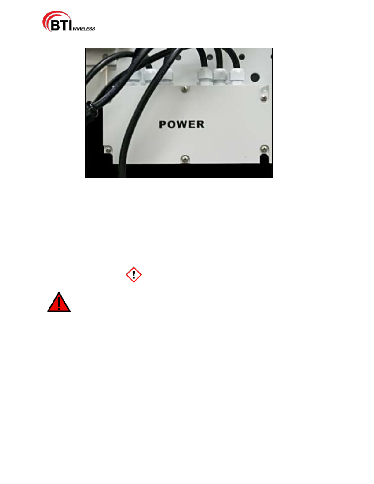
1. Route the power cable between the AC power port, located on the bottom of the enclosure and the
nearest AC power junction box as shown Figure 4-16.
mBSC-H DAS System
Installation Manual Issue 7
© 2009-2014, BTI Wireless Page 33
Figure 4-16. Junction Box AC Power Cable Routing
2. Secure the cable between the AC power port and the AC power junction box. Leave sufficient slack in
the cable to allow it to be easily connected and disconnected from the AC power port.
3. Install any AC power supply wires that may be required between the AC junction box and the AC circuit
breaker box.
4. At the AC circuit breaker box, connect the AC power supply load wire to the circuit breaker.
5. Place the circuit breaker in the ON position and then test the connected end of the AC power cable for
proper voltage levels and correct polarity.
6. When testing is complete, PLACE THE CIRCUIT BREAKER IN THE OFF POSITION.
Danger: To avoid serious personal injury and equipment damage, always turn the AC power
off on the circuit breaker before connecting the any power cable to the AC power port.
7. Connect the power cable connector to the AC power port labeled “POWER”.
8. Tighten the coupling nut.
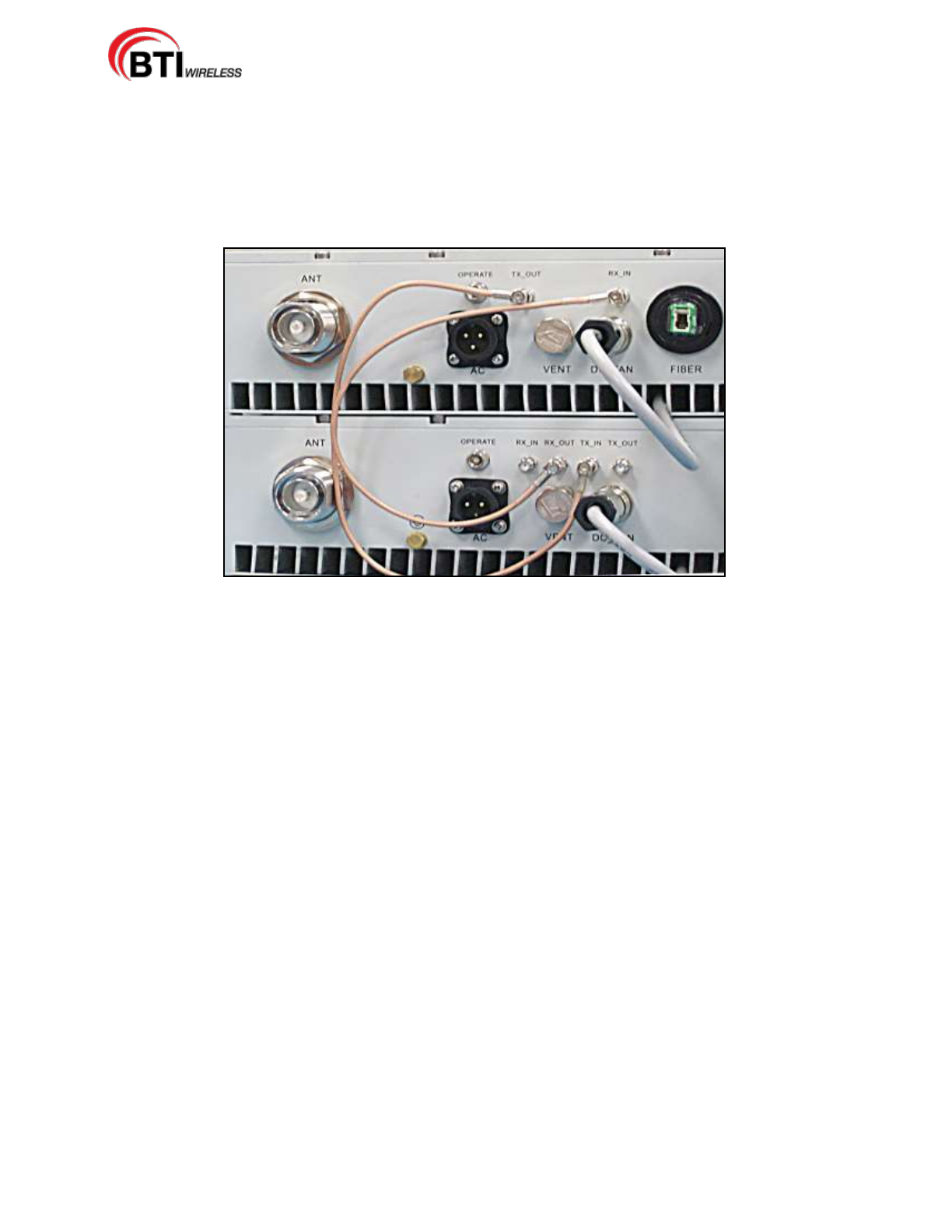
4.2.5.7 Slave Cable Connection
When two RU or more enclosures are installed for supporting multi-band. One is designated the Master
Remote Unit and each additional RU, up to two Units, are designated as slave Remote Units. The Master
and slave Unit(s) is specified by the frequency band. The Master Unit will separate the bi-directional signal
related to the frequency and provide the RF input signal to each slave Remote Unit. The connection
between Master and Slave is interfaced with the RF cable provided with the Remote Units.
Use the following procedure to install the antenna cable:
All designated slave RUs arrive with two RF cables.
Connect one RF cable to the port labeled “TX_OUT” on the MASTER Remote Unit User Interface.
mBSC-H DAS System
Installation Manual Issue 7
© 2009-2014, BTI Wireless Page 34
Connect the other end of the RF cable to the port labeled “TX_IN” on the SLAVE Remote Unit User
Interface as shown in Figure 4-17.
Connect the second cable to the port labeled "RX_IN" on the MASTER RU.
Connect the other end of the second RF cable to the port labeled "RX_OUT on the SLAVE RU.
Figure 4-17. RF cable connection between Master and Slave Remote Unit
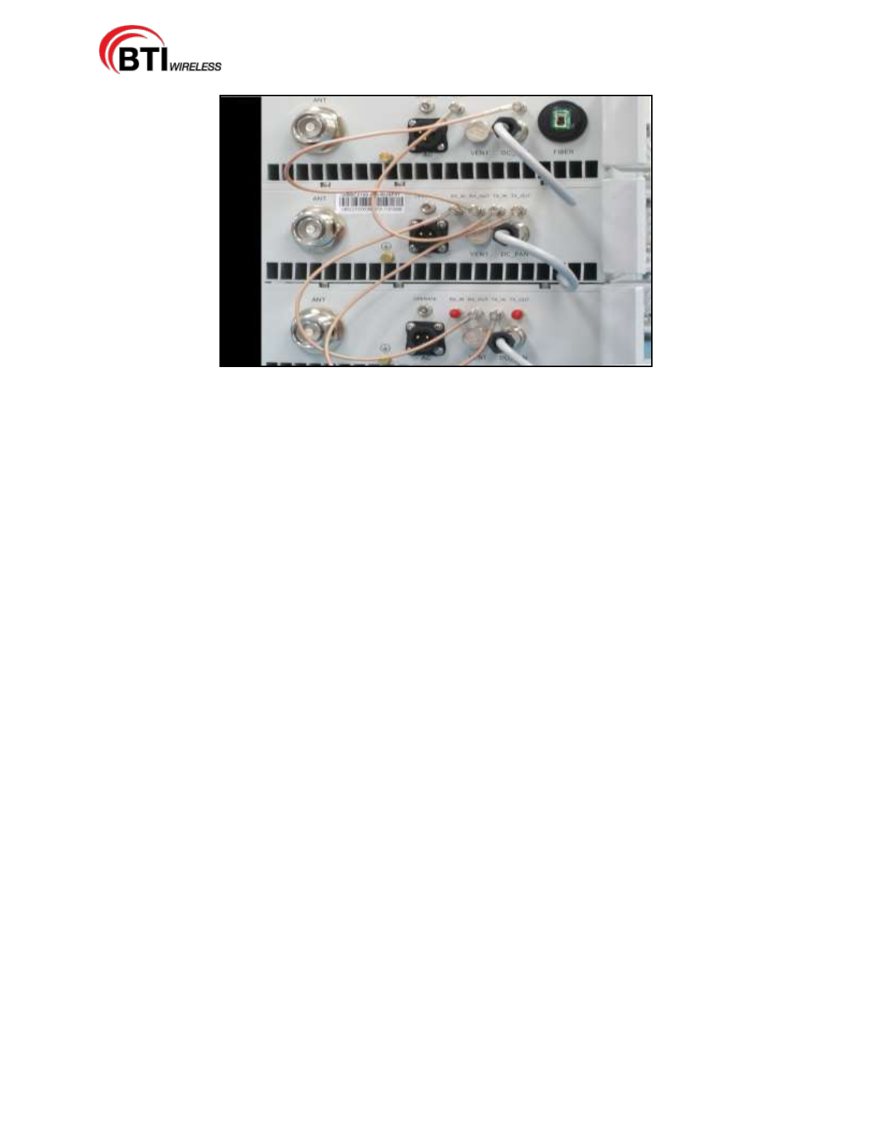
1 Slave to Slave Connection: Connect an RF cable into the port labeled "TX_OUT" on the first SLAVE
RU User interface.
2 Connect the other end of the RF cable to the port labeled "TX_IN" on the next SLAVE RU Unit.
Continue connecting all SLAVE RUs in this manner, as shown in Figure 4-18.
3 Connect an RF cable into the port labeled "RX_OUT" on the first SLAVE RU.
4 Connect the other end of the RF cable to the port labeled "RX_IN" on the next SLAVE RU. Continue
connecting all SLAVE RUs in this manner.
5 Power may now be applied to all Master and Slave Units used in this configuration.
mBSC-H DAS System
Installation Manual Issue 7
© 2009-2014, BTI Wireless Page 35
Figure 4-18. RF cable connection between Slave to Slave Remote Units
mBSC-H DAS System
Installation Manual Issue 7
© 2009-2014, BTI Wireless Page 36
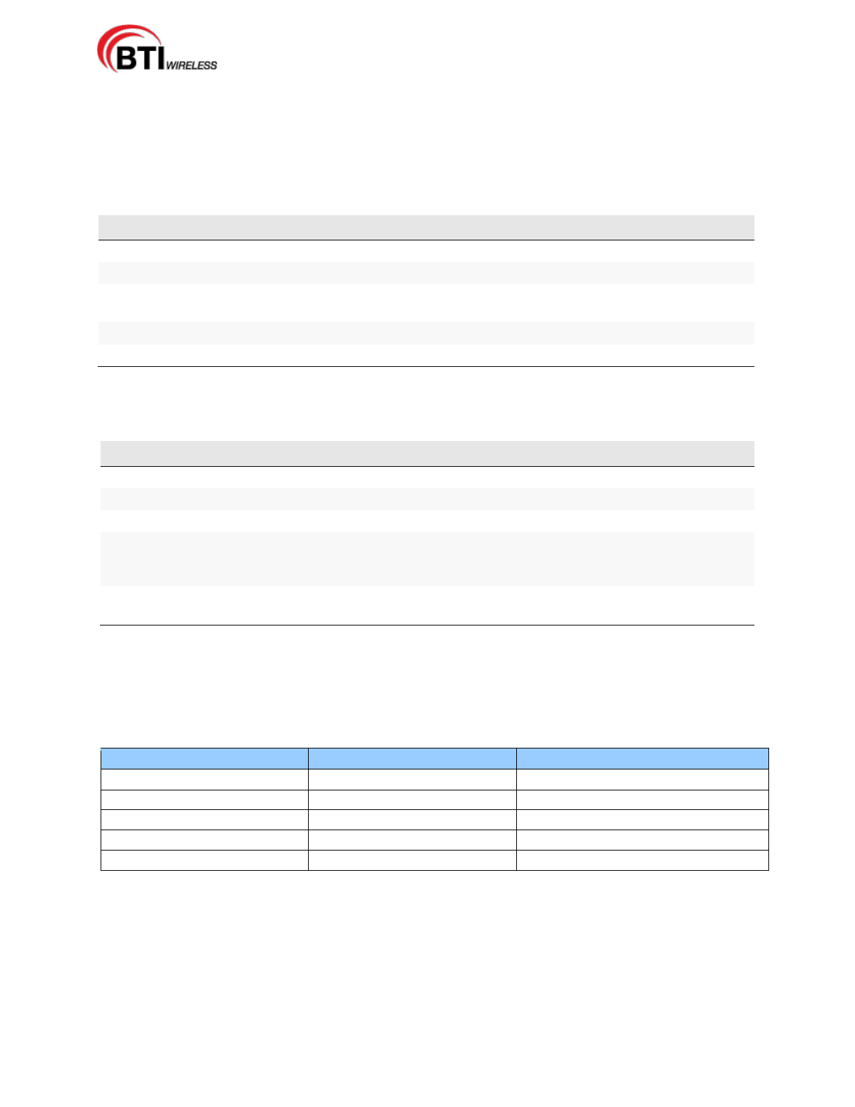
4.2.6 Remote Unit Installation Review
Use the following steps listed in Tables 4-3 and 4-4 to review the installation completion status
4.2.6.1 Mechanical Installation Review
Table 4-4. Remote Unit Mechanical Installation Check Lists
Items
Description
1
Confirm that the Unit is mounted firmly and is stable.
2
Verify that the Unit is affixed per manufacturer's specifications.
3
Check that all screws and nuts are secure, that spring washers sit flush upon the flat
washers, and that there are no missing flat washers and spring washers.
4
Examine each part and cable for breakage or damage.
5
Make sure the Unit is clean and free of dust and other contaminants
4.2.6.2 Electrical Installation Review
Table 4-5. Remote Unit Electrical Installation Check List
Items
Description
1
Verify that the grounding cable is secure.
2
Make sure that all the cable sheathings are not damaged.
3
Confirm that the connection to the cables are stable and are not loose or damaged.
4
Check that the cables are completely connected, but make sure there is enough slack, if
needed. Do not cross the cables and the cables should be bundled together in the same
direction.
5
Check that the connected cables are not bent more than the manufacturer's specified
maximum bending radius.
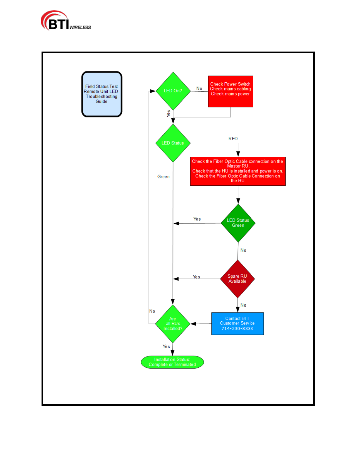
4.2.6.3 Field Status Test - Remote Unit LED Status Indicators
Perform a visual review of the LED Status indicators on the installed Remote Unit. The Remote Unit (RU)
status LED consists of a bi-colored LED of RED and GREEN. The high intensity LED is viewable from
ground level under most circumstances when using the BTI RU shroud system.
Table 4-6. Remote Unit LED Status Indicators
LED Indicator
Colors
Cycles
Test the LED
Red and Green Blink
1 flash per second
Master RU Fiber Alarm
Red Fast Blink
2 times per second
mRU and sRU Comm Fail
Red and Green Blink
1 time per second
PA/LNA shutdown or Other
Red Fast Blink
2 times per second
Normal Operation
Green Blink
1 times per second
mBSC-H DAS System
Installation Manual Issue 7
© 2009-2014, BTI Wireless Page 37
4.2.7 Troubleshooting

mBSC-H DAS System
Installation Manual Issue 7
© 2009-2014, BTI Wireless Page 38
mBSC-H DAS System
Installation Manual Issue 7
© 2009-2014, BTI Wireless Page 39
4.3 HOST UNIT INSTALLATION
Danger: Wet conditions increase the potential for receiving an electrical shock when
installing or using electrical power equipment. To avoid electrical shock, never install or use
the electrical equipment in a wet location.
Warning: Verify that the Unit has been ground with an earth-bonding cable to the grounding
connector.
4.3.1 Host Unit Installation Overview
The installation of the Host Unit consists of the following steps:
Table 4-6. Host Unit Installation Overview
Step
Operation Type
Operation Action
1
ELECTRICAL
VERIFY THAT THE UNIT IS GROUNDED
2
ELECTRICAL
CONFIRM THAT THE DC POWER CABLE IS INSTALLED AND
SECURE
3
ELECTRICAL
INSTALL THE BIU AND FIU MODULES
4
ELECTRICAL
INSTALL THE ALARM CONNECTORS (Optional)
5
ELECTRICAL
CONNECT THE BIU AND FIU
6
ELECTRICAL
CONFIRM THAT THE POI AND FAN (Opt. Equip.) ARE
CONNECTED
7
ELECTRICAL
CONNECT OPTIONAL EQUIPMENT TO THE BIU (if present)
8
ELECTRICAL
CONNECT THE FIBER OPTIC CABLES
9
INSTALLATION
REVIEW
CONFIRM THE ELECTRICAL INSTALLATION, TABLE 4-10
HOST UNIT ELECTRICAL INSTALLATION CHECKLIST
10
TROUBLESHOOTING
INSTALLATION TROUBLESHOOTING GUIDE
4.3.2 Installation Hardware And Tools
The Host Units may be shipped individually or shipped factory pre-installed in optional cabinets. Table 4-7
lists the cables and hardware provided by the manufacturer. Additional hardware may be needed,
depending on the site requirements, and may be ordered through Customer Service (Section 6).
Table 4-7. Host Unit Cables and Hardware
Single Host Unit
Hardware and Fasteners
Customer Install
Factory Install
Rec'd
CABINET (Optional)
1
HU DC POWER CABLE
1
ALARM CONNECTORS
8
FIU-S INTERFACE CABLE
3
FIU-NS INTERFACE CABLE
4
GROUNDING CABLES
1
POI GROUNDING CABLE
(Optional)
1
mBSC-H DAS System
Installation Manual Issue 7
© 2009-2014, BTI Wireless Page 40
Single Host Unit
Hardware and Fasteners
Customer Install
Factory Install
Rec'd
POI INTERFACE CABLE
4
The following is a list of tools and any additional materials required for the Host Unit installation:
Small Phillips screwdriver
Wire cutters
Wire Harness (Required for Expanded Third Party Alarm)
4.3.3 Unpacking And Inspection
This section provides the instruction for receiving the equipment shipment, verifying all parts have been
received and checking that no damage has occurred during transportation. The Host Unit includes the
following items:
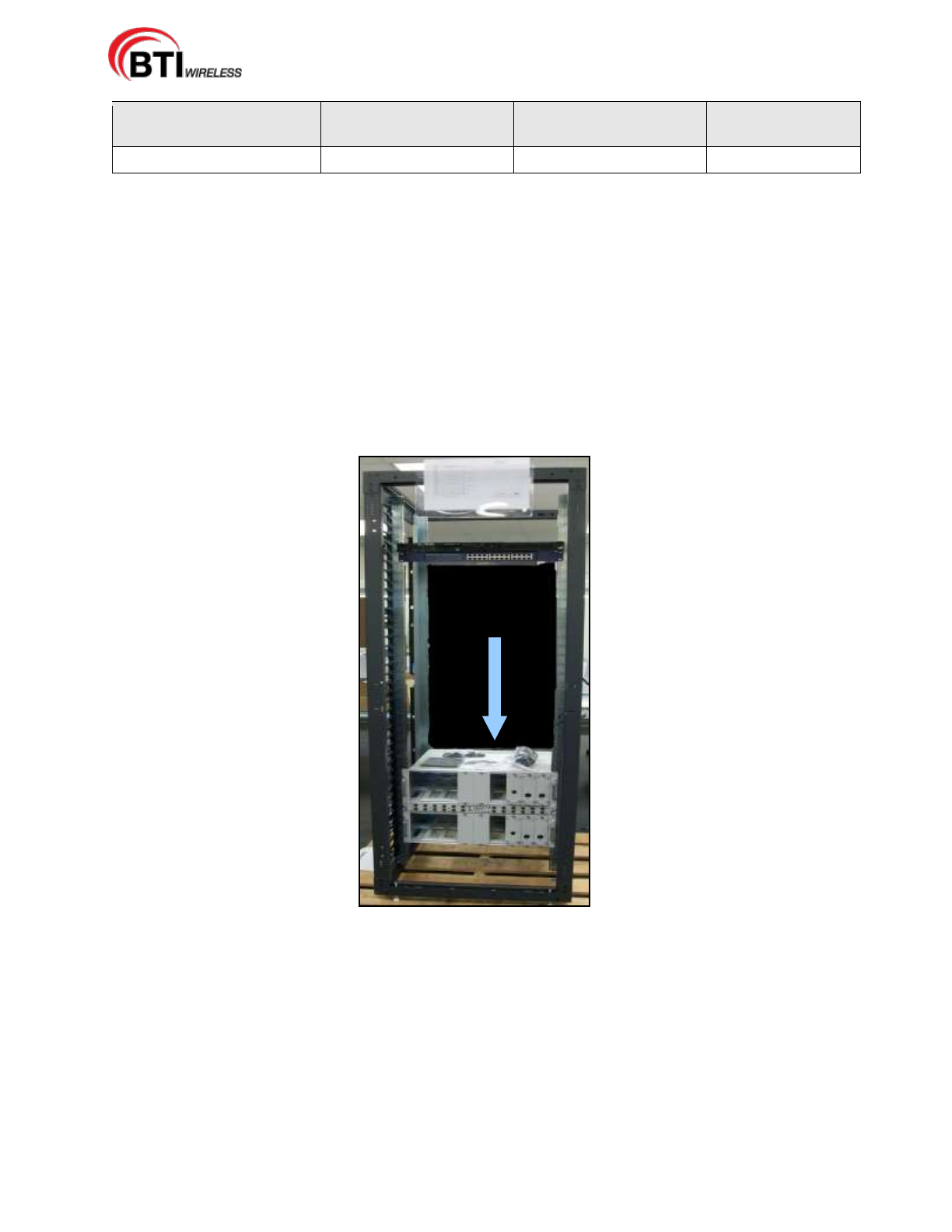
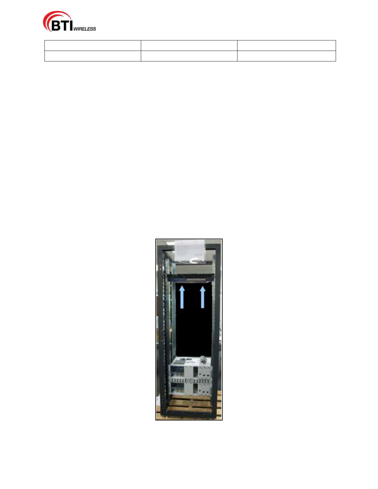
Optional Cabinet with Host Unit installed as shown in Figure 4-19.
Hardware and Fasteners described in Table 4-7, Section 4.3.2
Figure 4-19. Host Unit Cabinet
Use the following procedure to unpack and inspect the Host Unit and accessories:
1. Open the shipping packet and carefully unpack the cabinet or individual Host Unit from the protective
packing material.
2. Verify receipt of hardware and fasteners using Table 4-7
3. Check each optional cabinet for broken or missing parts. Check each Host Unit module for any
damage, particularly the Fiber Optic Port. If there is any damage or missing parts, contact BTI (Section
6) for an RMA and to reorder parts, if any replacement parts are required.
mBSC-H DAS System
Installation Manual Issue 7
© 2009-2014, BTI Wireless Page 41
NOTE: Check particularly for any damage to the fiber optic connectors on the FIU
module. Check the power connectors located at the back of the Host Unit and check
the back plane connectors located inside the Host Unit for any damage.
.
4.3.4 Electrical Installation
4.3.4.1 Electrical Safety Precautions
Please read the general Safety Precautions presented in Section 1.2 Safety Precautions
1. Follow the instructions for installation provided in this manual to prevent serious
accidents including loss of life, severe personal injury or extensive property damage.
2. The Unit must be grounded before connecting any power supply. Grounding is a
required precautionary measure. Grounding instructions are provided and should be
followed for safety.
3. Electrical and electronic components can be destroyed by incorrectly wired connections.
4. Cable connector materials must meet manufacturer specifications to avoid corrosion at the
connectors.
5. Compliance with the surge requirement of EN 61000-4-5 (fine protection) has been met by this
Unit. Installing additional external surge protection, depending on the individual application, via
local supply connection and/or coarse protection is recommended to avoid damage caused by
electrical surges.
mBSC-H DAS System
Installation Manual Issue 7
© 2009-2014, BTI Wireless Page 42
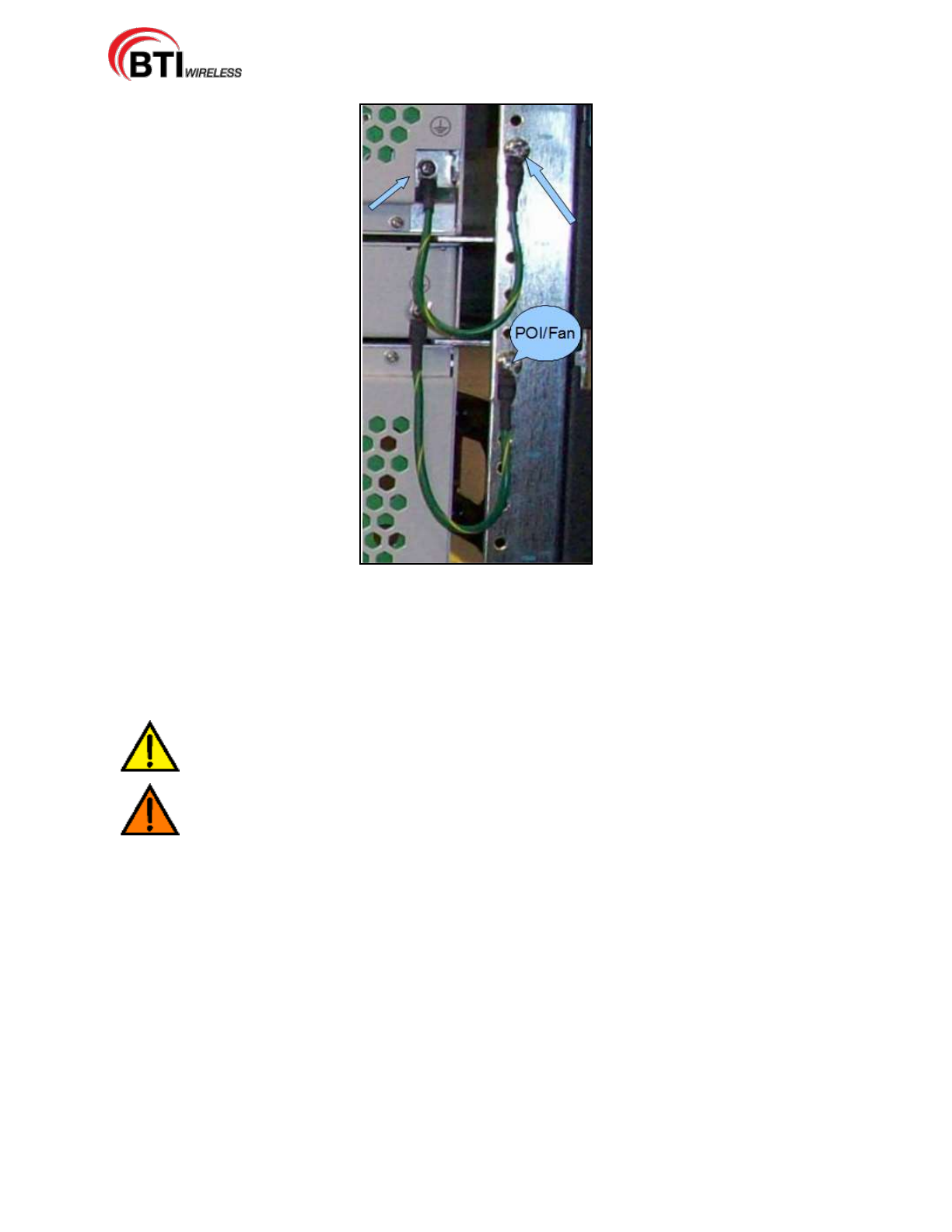
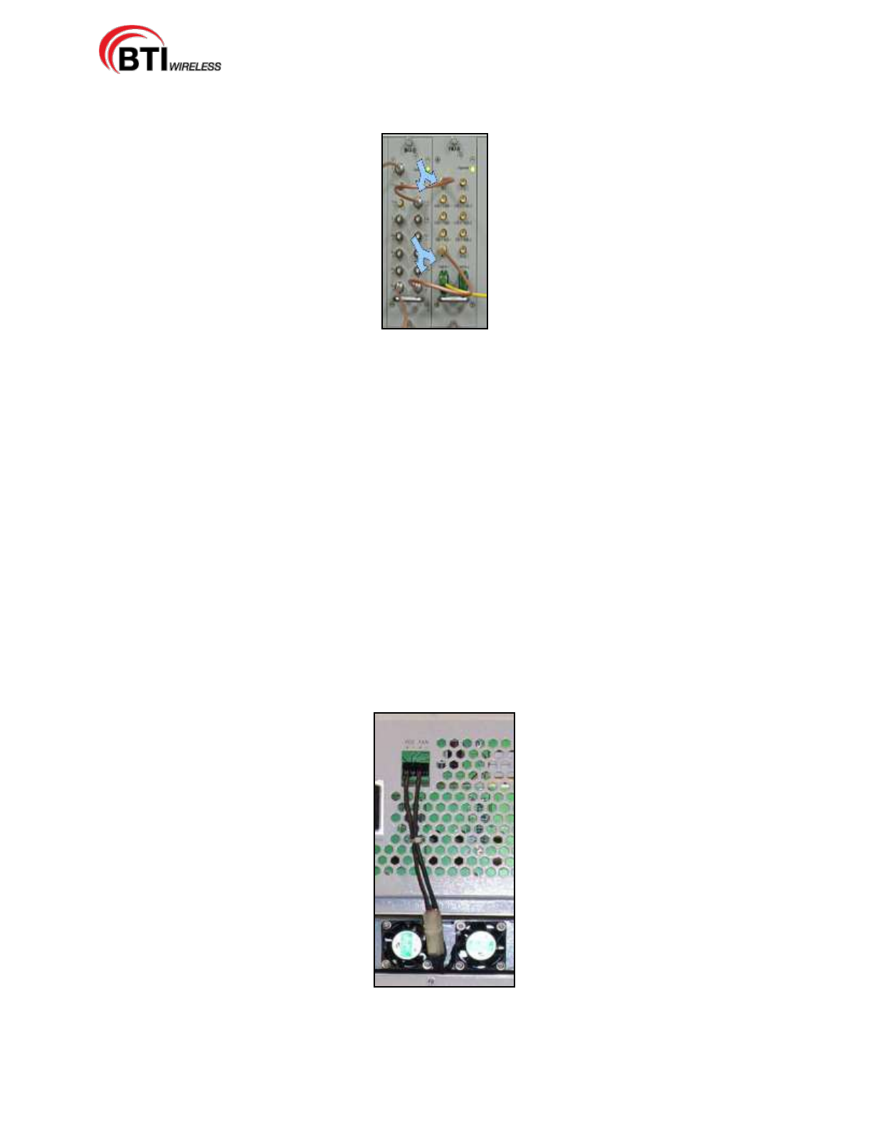
4.3.4.2 Grounding
The Unit must be grounded. The Host Unit is grounded during a factory installation in the optional
cabinet with an earth-bonding cable connected to the provided grounding connection. Do not
connect external devices to the grounding connection.
Please verify the Unit is securely grounded. If it is no longer securely grounded, please use the following
procedure to ground the Unit:
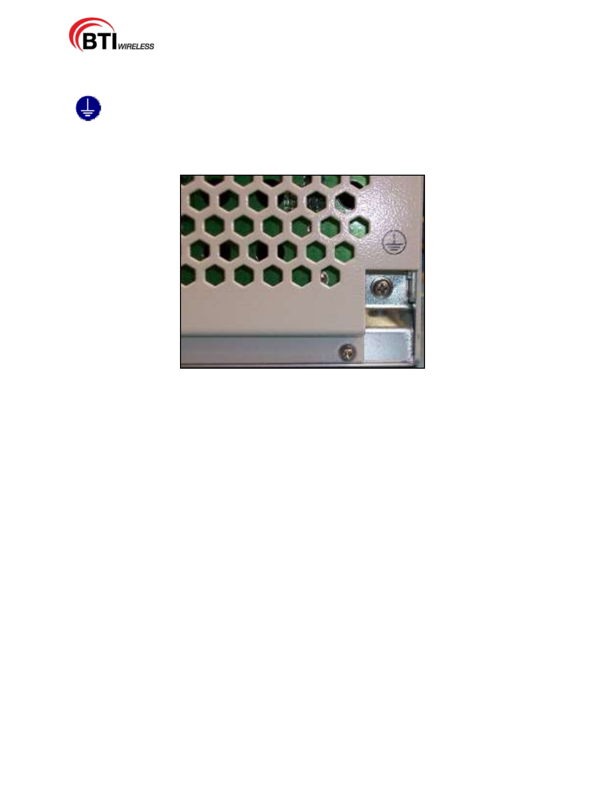
Figure 4-20. Host Unit Grounding Connection
1. Find the screw at the bottom right corner of the Host Unit as shown in Figure 4-20.
2. Loosen the screw located on the grounding connection.
3. Connect the cabinet mounted earth-bonding cable between the two lock and flat washers as shown in
Figure 4-21. Ensure the grounding surface is clean and free of paint, insulating material or
contaminants.
mBSC-H DAS System
Installation Manual Issue 7
© 2009-2014, BTI Wireless Page 43
Figure 4-21. Grounded Host Unit (shown with optional POI Unit, also grounded)
4. Tighten the screw, making sure the cable is securely connected before moving to the next phase of the
installation.
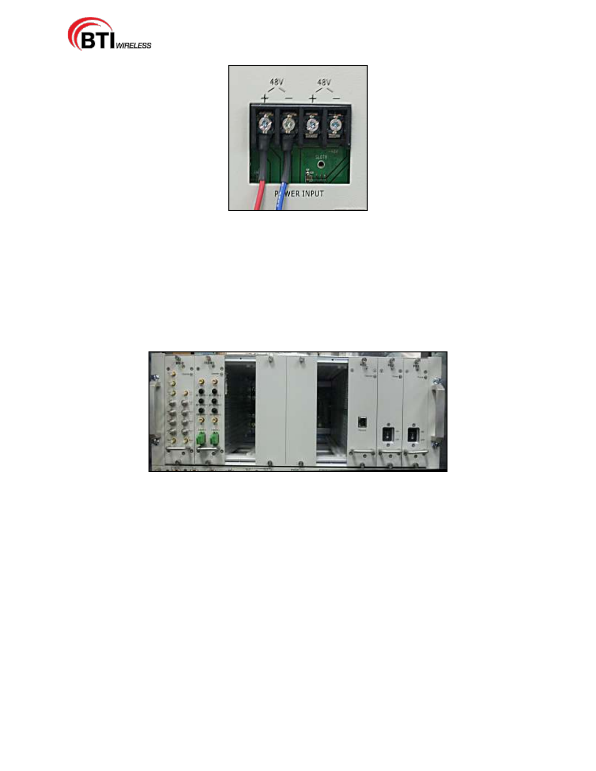
4.3.4.3 DC Power Cable Connection
Danger: Please use caution when working with DC power. Ensure all power is disconnected
before working on power circuit.
Warning: Verify that the Unit has been ground with an earth-bonding cable to the grounding
connector.
The DC power cable is connected during factory pre-installation.
mBSC-H DAS System
Installation Manual Issue 7
© 2009-2014, BTI Wireless Page 44
Figure 4-22. Factory Installed DC Power Cable
1. Confirm electrical polarity of the power cables to match the customer provided DC power system.
2. Verify the DC power cable is attached securely, as shown Figure 4-22.
3. If the DC power cable is not secure, turn off all associated DC power to the Host Unit, and secure the
power cables as shown.
4.3.4.4 Install the BIU and FIU modules
Figure 4-23. BIU and FIU modules
1. Remove the blank module covers for the chosen module slot locations.
2. Slide the BIU and FIU modules in to each separate designated module slot, Figure 4-23.
3. Secure the screws at the top and bottom of each module.
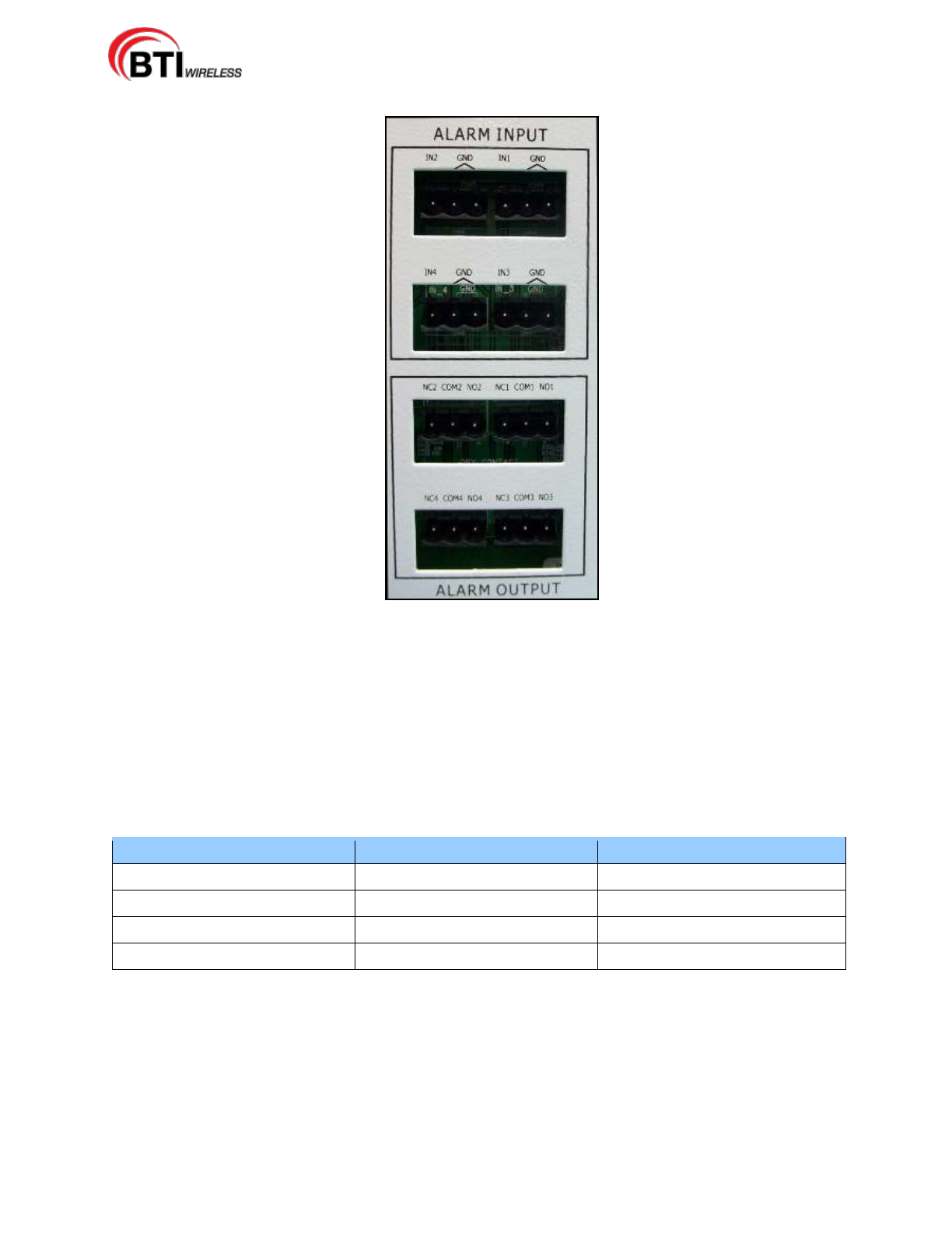
4.3.4.5 Alarm Installation
The Alarm interface is an optional customer centered configuration.
The Alarm Input configuration gives the user the means to monitor third party alarms, such as battery or
intrusion alarms.
The Alarm Output configuration provides the customer with the means to monitor major or minor alarms
via Form C relay.
The alarm interface is located at the back of the Host Unit as shown in Figure 4-24.
mBSC-H DAS System
Installation Manual Issue 7
© 2009-2014, BTI Wireless Page 45
Figure 4-24. Alarm Interface
1. With wire cutting tools, prepare the connecting wires.
2. Loosen the screws in each connector.
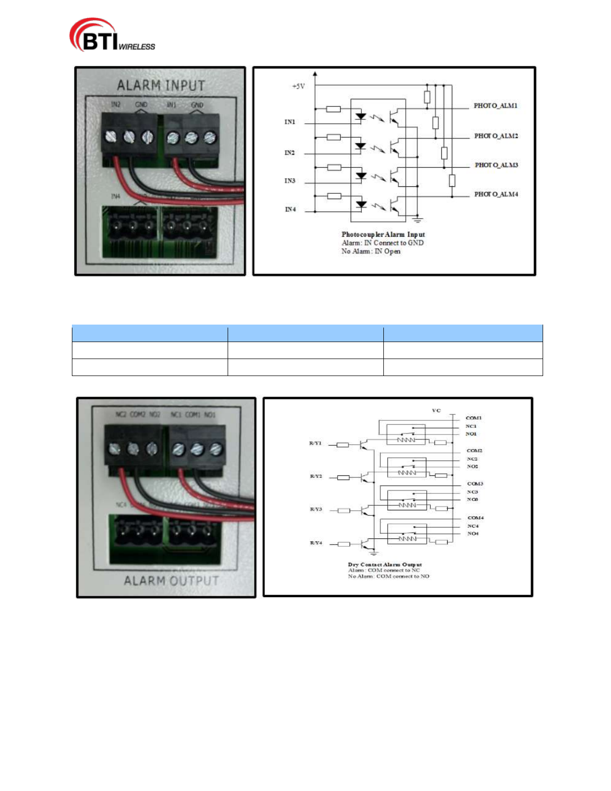
3. Use the Input Alarm configurations shown in Table 4-8 and the Output Alarm configurations in Table
4-9 to determine the wire placement.
4. Slide the bared wires into the slot under the screw and tighten securely.
5. Plug all the alarm connectors into the Alarm Input interface as shown in Figure 4-25 and Figure 4-26.
Table 4-8. Input Alarm Configuration
NMS Alarm Status
Alarm
No Alarm
Expanded Alarm 1 (User Defined)
IN1/GND
IN1
Expanded Alarm 2 (User Defined)
IN2/GND
IN2
Expanded Alarm 3 (User Defined)
IN3/GND
IN3
Expanded Alarm 4 (User Defined)
IN4/GND
IN4
mBSC-H DAS System
Installation Manual Issue 7
© 2009-2014, BTI Wireless Page 46
Figure 4-25. Input Alarm Installation (Alarm On)
Table 4-9. Output Alarm Configuration
Alarm Type
On
Off
Major
COM1/NC1
COM1/NO1
Minor
COM2/NC2
COM2/NO2
Figure 4-26. Output Alarm Installation (Alarm On)
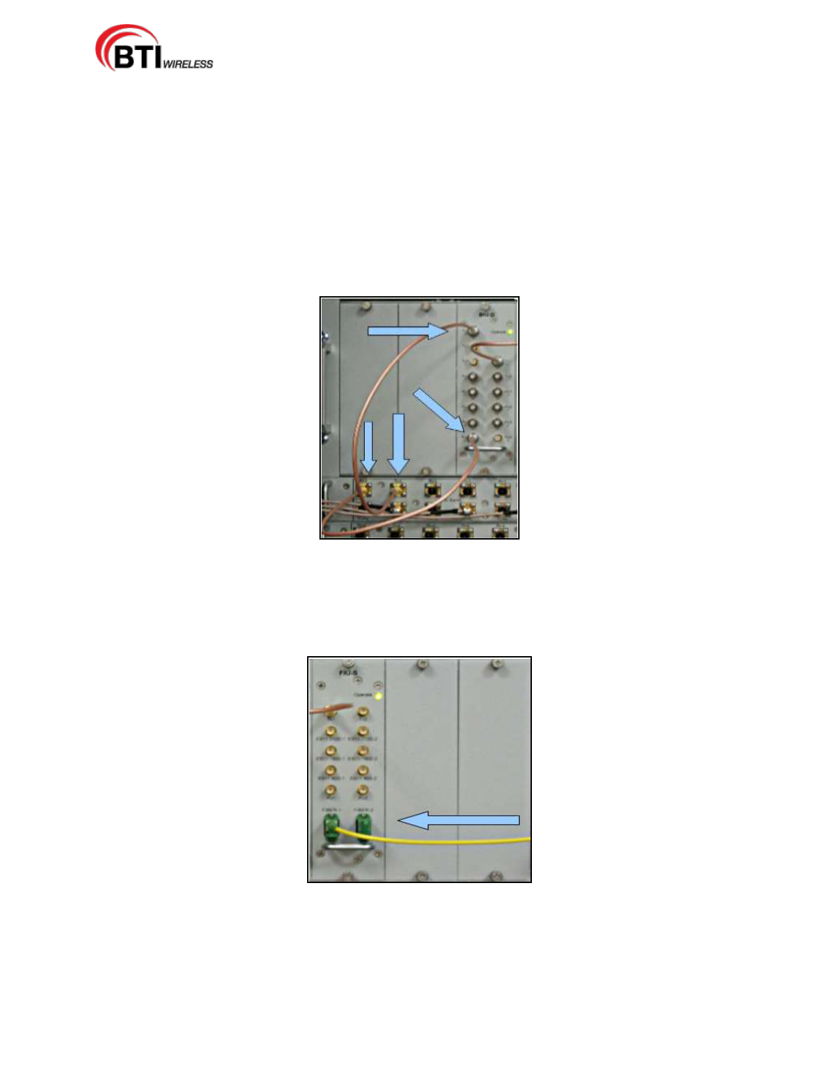
4.3.4.6 Connect the BIU/FIU Modules
Connect the BIU to the FIU-S with the provided interface cable using the following procedure:
1. Connect one end of the interface cable to the BIU port labeled "Tx1 Out".
2. Connect the other end of the cable to the FIU-S port labeled "Tx1".
3. Connect a second interface cable to the BIU port labeled "Rx4".
mBSC-H DAS System
Installation Manual Issue 7
© 2009-2014, BTI Wireless Page 47
4. Connect the other end of the cable to the FIU port labeled "Rx1", Figure 4-27.
Figure 4-27. Connect the BIU to the FIU
For a two BIU and FIU-NS configuration, use the additional provided interface cables and the following
procedure:
5. Connect the one end of the interface cable to the FIU-NS port labeled "Tx1".
6. Connect the end of the second interface cable to the FIU-NS port labeled "Tx2".
1. Connect one end of the interface cable to the BIU port labeled "Tx1 Out".
2. Connect the end of the second interface cable to the port labeled "Tx1 Out" of the second BIU.
3. Connect the end of the third interface cable to the FIU-NS port labeled "Rx1".
4. Connect the other end of the fourth interface cable to the FIU-NS port labeled "Rx2"
5. Connect the third interface cable to the BIU port labeled "Rx4".
6. Connect the fourth interface cable to "Rx4" of the second BIU.
4.3.4.7 Optional Equipment Installation
The POI and Fan, (if ordered) are factory installed. Please verify the POI and Fan are securely connected
as shown in Figure 4-28.
Figure 4-28 POI and FAN Installation
mBSC-H DAS System
Installation Manual Issue 7
© 2009-2014, BTI Wireless Page 48
4.3.4.8 Connect POI to BIU
The Point of Interface (POI) is an optional component. The POI is connected to the BIU, Figure 4-29,
using the following procedure:
1. Connect one end of a POI interface cable into the BIU port labeled "Tx1 In".
2. Connect the other end of the cable to the POI port labeled "Tx-L".
3. Connect the one end of a POI interface cable into the BIU port labeled "Rx4 Out".
4. Finally, connect the other end of the cable to the POI port labeled "Rx-L".
Figure 4-29. POI to BIU Connection
4.3.4.9 Connect the Fiber Optic Cable
The Fiber optic cable is connected to the FIU module by attaching the cable to the port labeled "Fiber-1" as
shown in Figure 4-30.
Figure 4-30. Fiber Optic Cable Connection to the FIU Module
4.3.5 Host Unit Installation Review
4.3.5.1 Electrical Installation Review

mBSC-H DAS System
Installation Manual Issue 7
© 2009-2014, BTI Wireless Page 49
Table 4-10. Host Unit Electrical Installation Check List
Items
Description
1
Verify that the grounding cable is secure.
2
Confirm that the power cable connection is stable and is neither loose or damaged and
that the electrical polarity is correct.
3
Verify that the fiber optic cable is securely connected.
4
Check that all installed cables are securely connected.
5
Confirm that the alarm connectors are securely connected.
mBSC-H DAS System
Installation Manual Issue 7
© 2009-2014, BTI Wireless Page 50
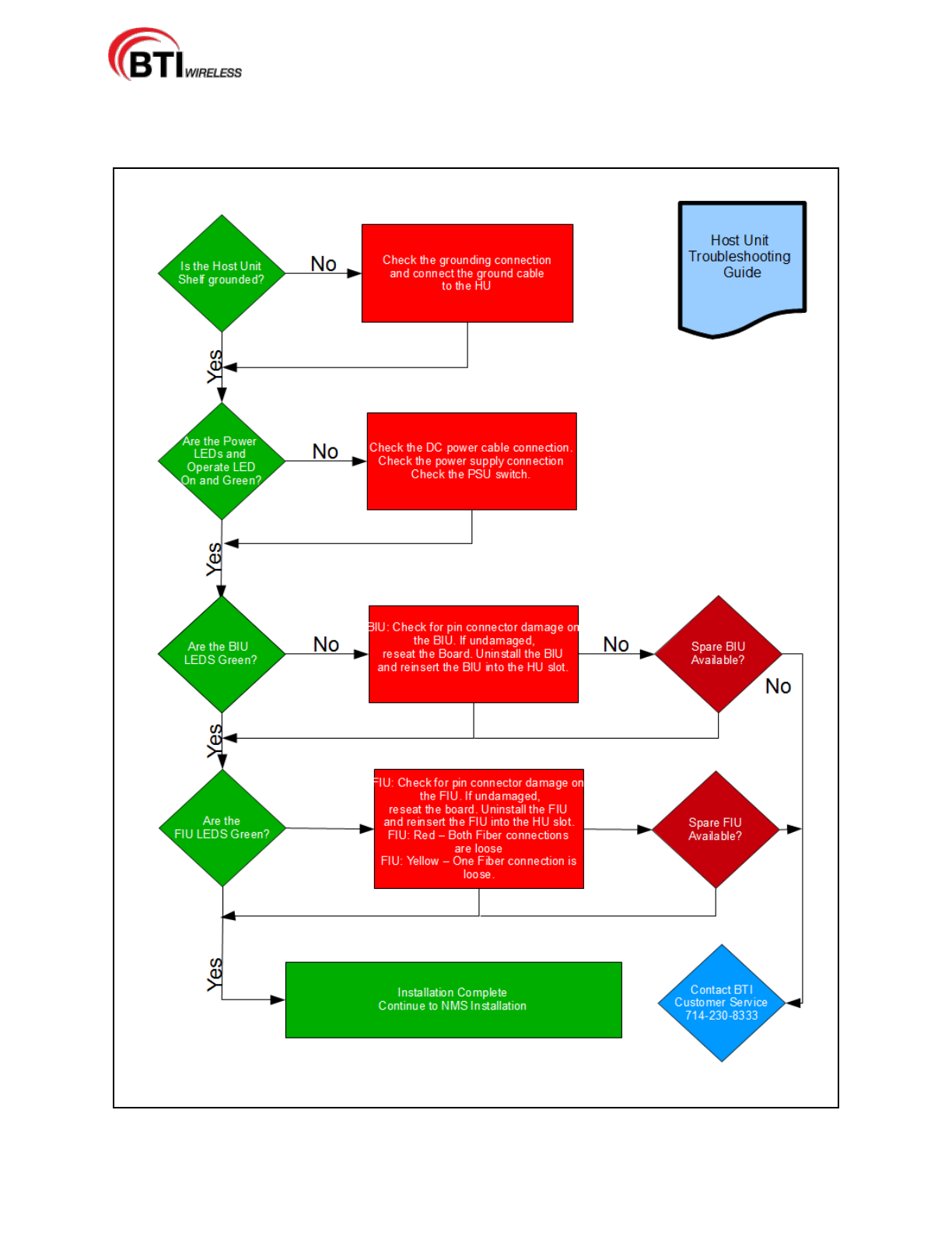
4.3.6 Troubleshooting
mBSC-H DAS System
Installation Manual Issue 7
© 2009-2014, BTI Wireless Page 51
4.4 NMS INSTALLATION
Caution: Network security may be compromised when accessing external Internet
connectivity. The use of established security software is recommended.
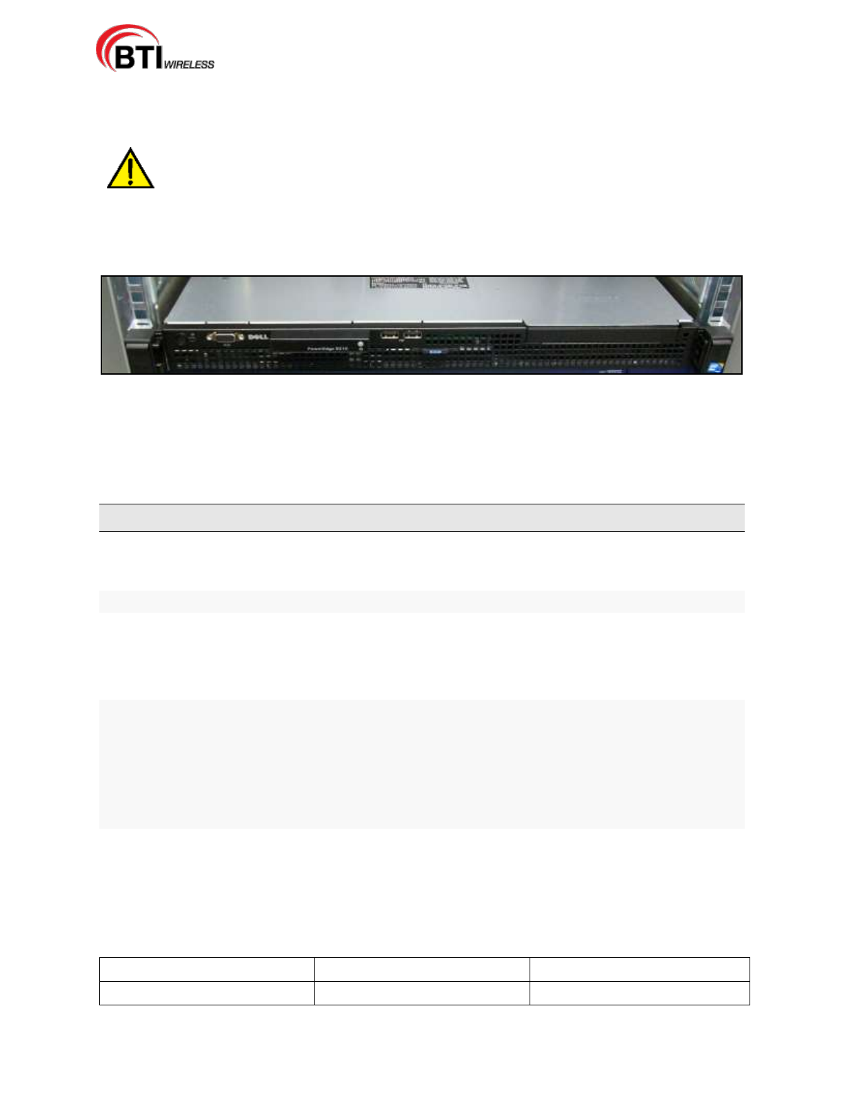
The NMS software is pre-installed on the Network Management Server and the NMS server arrives
pre-installed in the optional Host Unit cabinet. This section provides instruction for installing the NMS
software on a customer laptop or desktop and setting initial software parameters.
Figure 4-31. NMS Server
4.4.1 Installation Overview
The installation of the Network Management System consists of the following steps:
Table 4-11. NMS Installation Overview
Step
Operation Type
Operation Action
1
SYSTEM SET-UP
VERIFY SERVER SOFTWARE IS OPERATIONAL
2
SYSTEM SET-UP
INSTALL SYSTEM SOFTWARE ON TO CUSTOMER
MONITORING EQUIPMENT
3
SYSTEM SET-UP
LAUNCH NMS SOFTWARE
4
CONFIGURE
CONFIGURE MANAGER ACCOUNT
5
CONFIGURE
SET-UP USER ACCOUNTS
6
CONFIGURE
SOFTWARE SYSTEM PARAMETERS
7
UPDATE/UPGRADE
SOFTWARE/FIRMWARE UPGRADE INSTALL
8
INITIAL SOFTWARE
INSTALLATION
REVIEW
CONFIRM SOFTWARE SET-UP INSTALLATION, TABLE 4-13
NMS INITIAL SOFTWARE INSTALLATION CHECKLIST
9
UPGRADE
INSTALLATION
REVIEW
CONFIRM FIRMWARE UPDATE AND SOFTWARE UPGRADE
INSTALLATION, TABLE 4-14 NMS UPGRADE SOFTWARE
INSTALLATION CHECKLIST
10
TROUBLESHOOTING
INSTALLATION TROUBLESHOOTING GUIDE
4.4.2 Installation Hardware and Tools
The NMS server is shipped pre-installed in the optional Host Unit cabinet. Table 4-12 lists the accessories
provided by the manufacturer. Additional accessories may be needed, depending on the site requirements,
and may be ordered through Customer Service (Section 6).
Table 4-12. NMS Cables and Accessories
NMS ACCESSORY
Quantity
Received
SOFTWARE CD-ROM
1
mBSC-H DAS System
Installation Manual Issue 7
© 2009-2014, BTI Wireless Page 52
NMS ACCESSORY
Quantity
Received
AC POWER CABLE
1
The following is a list of tools and any additional materials required for NMS software installation:
Laptop, Desktop PC and/or Terminal
Crossover Cable
Hub and/or Router
4.4.3 Unpacking And Inspection
This section provides the instructions for receiving the equipment shipment and verifying that no damage
has occurred during shipping. The NMS software is pre-installed on the server which is shipped with the
following:
Optional cabinet with NMS server and Host Unit installed as shown in Figure 4-32.
Installation cables and accessories as described in Table 4-12, Section 4.4.2.
Use the following procedure to unpack and inspect the NMS server and accessories:
1. Open the shipping packet and carefully unpack the cabinet from the protective packing material.
2. Verify receipt of accessories using Table 4-12
3. Check the server for visual damage. If there is any damage, contact BTI (Section 6) for further
instructions including an RMA, if necessary.
Figure 4-32. NMS Server
4.4.4 Verify Server software
mBSC-H DAS System
Installation Manual Issue 7
© 2009-2014, BTI Wireless Page 53
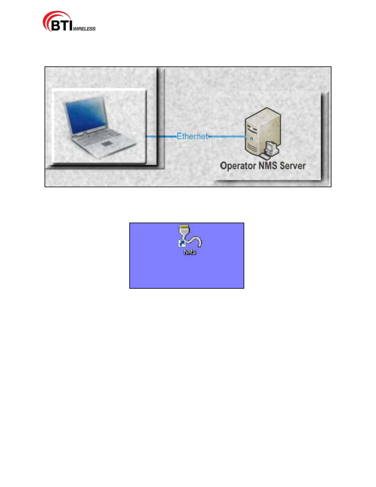
1. Connect the laptop, PC or terminal to the server through the hub using a crossover cable, Figure 4-33.
The monitoring device may also be plugged directly into the server with a crossover cable.
Figure 4-33. Connecting the Monitoring Device to the Server
2. Locate the NMS icon on the screen of the monitoring device, Figure 4-34.
Figure 4-34. Locate NMS Icon
4.4.5 Initial System Setup
4.4.5.1 CD-ROM Install
The CD-ROM install is used to install NMS on to a Laptop or Desktop Computer. Use the following
procedure to install the application on to the computer:
1. Open the CD drive on the machine.
2. Place the CD into the drive and close the drive.
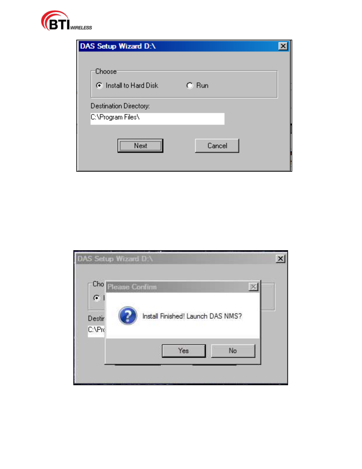
3. The CD will begin the install wizard, Figure 4-35.
4. The wizard copies the files to the %ProgramFiles% folder. The default destination directory may be
changed, if desired.
mBSC-H DAS System
Installation Manual Issue 7
© 2009-2014, BTI Wireless Page 54
Figure 4-35. DAS Setup Wizard
4.4.5.2 Launch NMS
1. After copying the files, the Wizard will ask to launch NMS, Figure 4-36.
2. Select Yes.
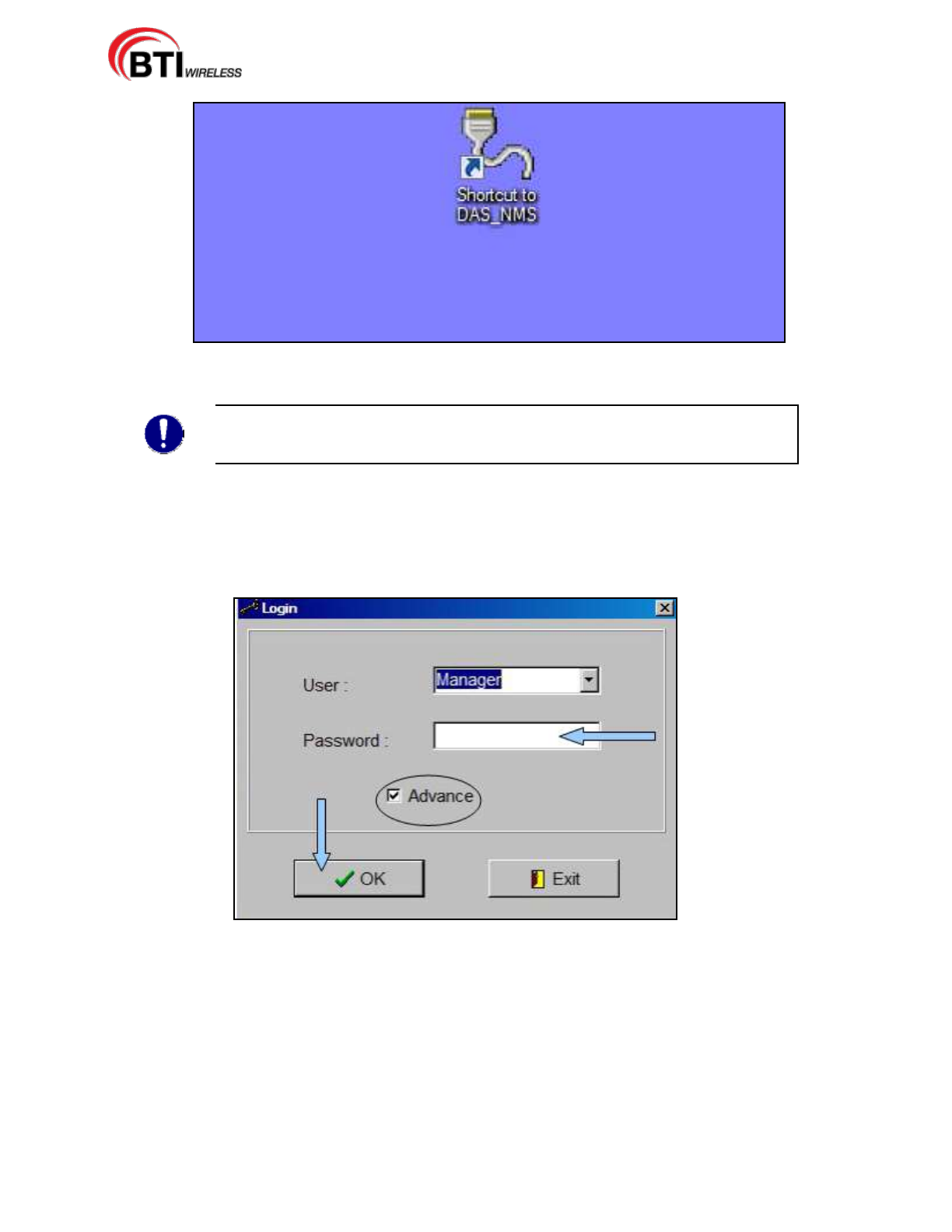
3. The Wizard simultaneously places a shortcut on to the desktop of the computer as shown in Figure
4-37. Double clicking on the NMS icon on the desktop also launches the NMS Login screen.
Figure 4-36. NMS Launch from Wizard Installation
mBSC-H DAS System
Installation Manual Issue 7
© 2009-2014, BTI Wireless Page 55
Figure 4-37. NMS Desktop Shortcut
NOTE: Occasionally, there are compatibility problems that cause a configuration
conflict when setting up the NMS. Follow the steps shown in the Troubleshooting
Guide. If this does not resolve the issue, contact Customer Service (Section 6).
4. Verify that the Advance box is checked and then click in the password field, Figure 4-38.
5. Enter the following default password: 1
6. Click on OK. The NMS Command Console is then launched.
Figure 4-38. NMS Login Screen
4.4.6 Initial Start-up Configuration
Once NMS is installed on the machine, the command console or main screen is used to navigate through
various NMS menus to configure both the software system parameters and the DAS system parameters.
This section covers the software system parameters needed to set-up an initial install.
Main access to the NMS software configuration is through the System(S) drop down on the Menu bar as
shown in Figure 4-39. User accounts may also be accessed through the User Icon on the Command
toolbar as shown in Figure 4-40. The software system configuration includes the ability to access the
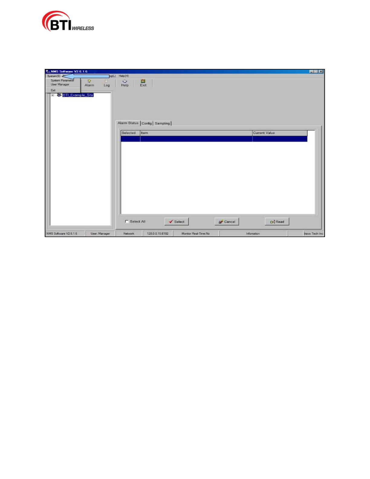
mBSC-H DAS System
Installation Manual Issue 7
© 2009-2014, BTI Wireless Page 56
following functions:
Access and manage User Accounts and passwords (Add/Modify/Delete)
Modify parameter defaults.
Figure 4-39. System (S) Drop Down Menu
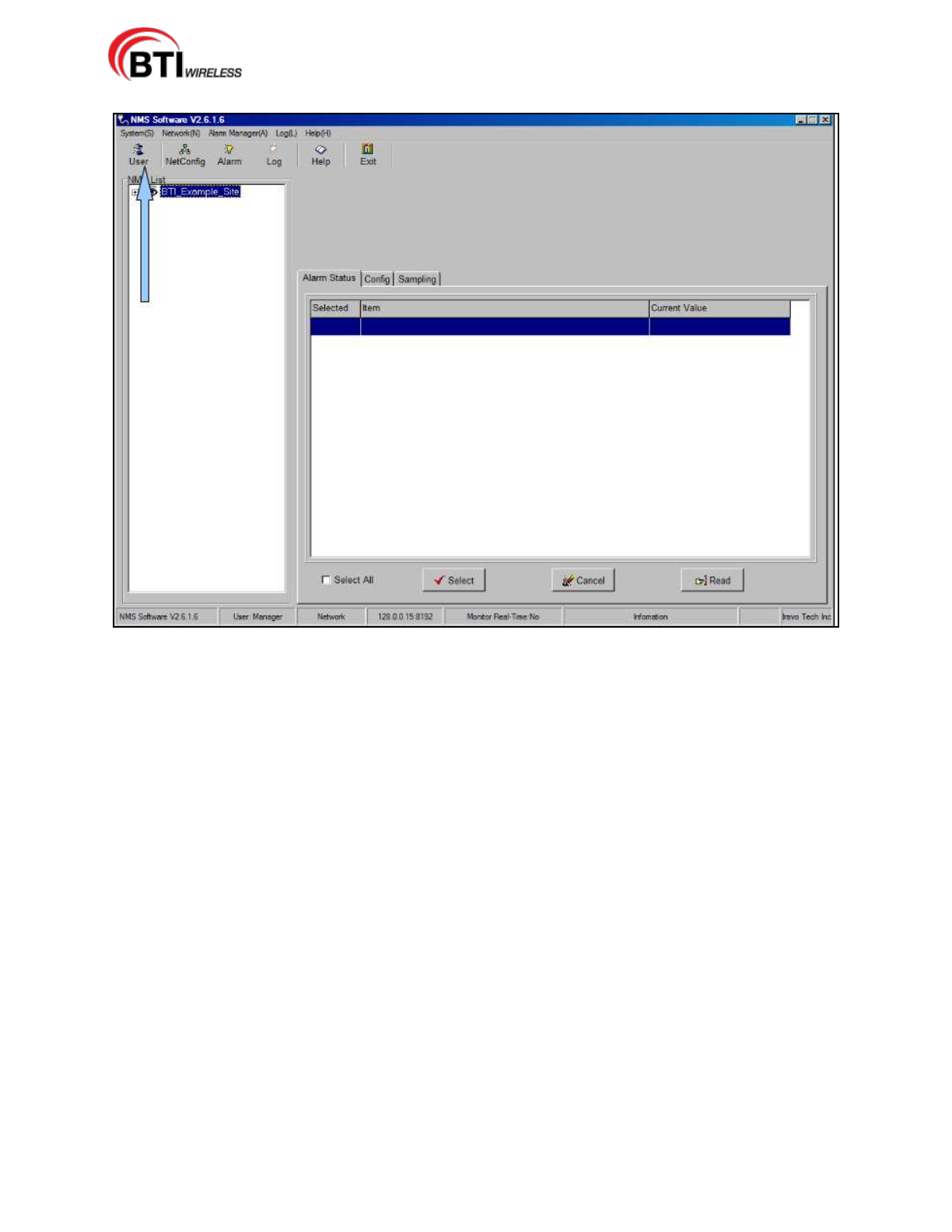
mBSC-H DAS System
Installation Manual Issue 7
© 2009-2014, BTI Wireless Page 57
Figure 4-40. User Account Icon
4.4.6.1 Modify Default Accounts
The NMS User Manager comes with two default entries shown in the User list. For security reasons,
changing the default manager account and password is highly recommended. The default User account
may also be modified by overwriting the default information. The following procedure details the steps
necessary to change the default accounts:
1. Using either the System(S), Figure 4-39 or the User icon, Figure 4-40, access the User Manager
screen, Figure 4-41.
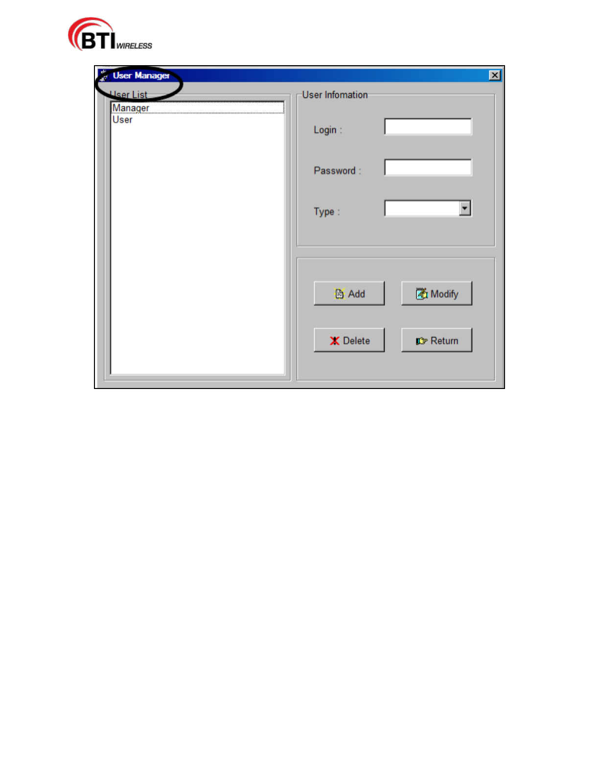
mBSC-H DAS System
Installation Manual Issue 7
© 2009-2014, BTI Wireless Page 58
Figure 4-41. User Manager Screen
2. Select Manager in the User List, Figure 4-42 to see the default information.
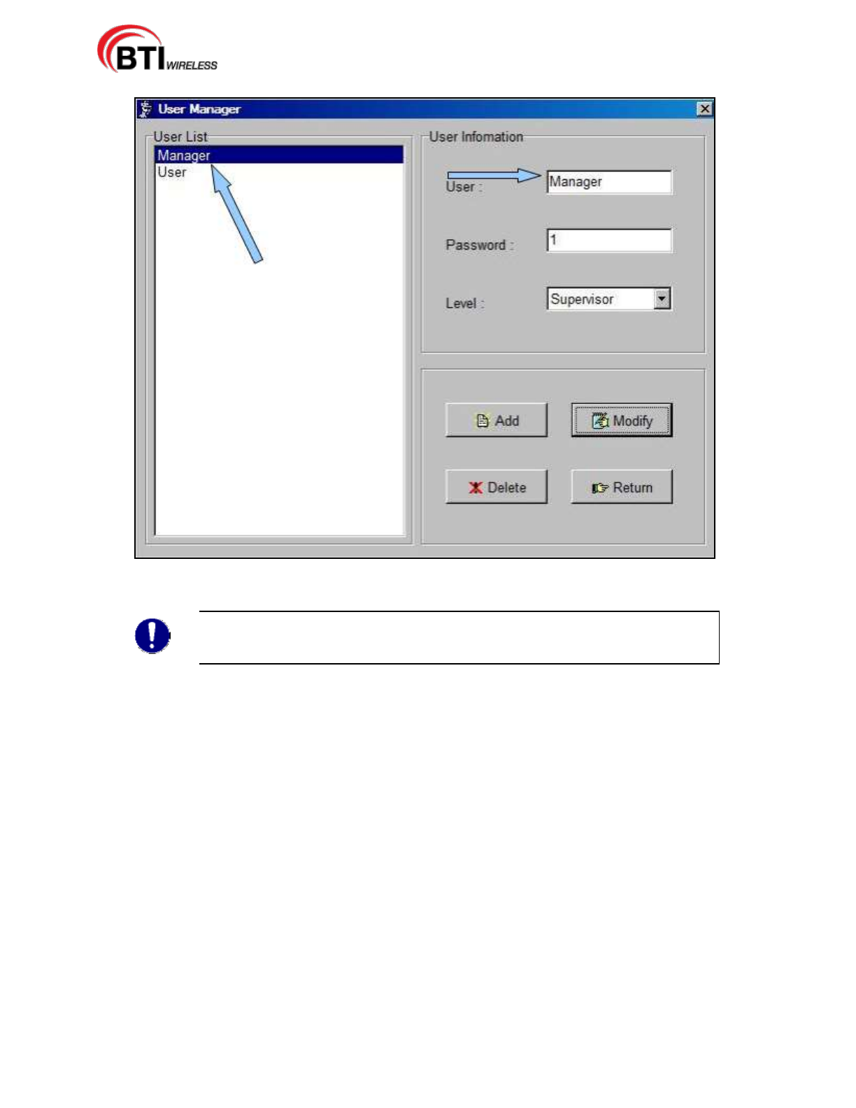
mBSC-H DAS System
Installation Manual Issue 7
© 2009-2014, BTI Wireless Page 59
Figure 4-42. Manager Default Information
3. Delete the default entries, Figure 4-43 and enter the new user name and password.
Note: There is a limit of 20 Alpha-Numeric characters for both User name and
password entries. User names are selectable from the Login screen drop down
menu, once entered into the system. Passwords are case sensitive.
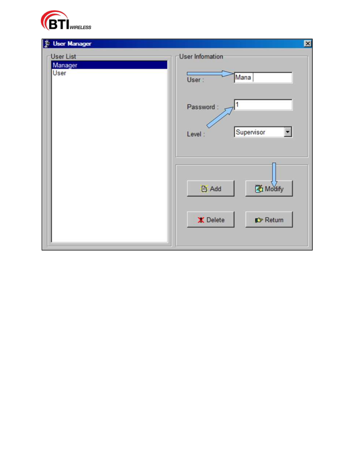
mBSC-H DAS System
Installation Manual Issue 7
© 2009-2014, BTI Wireless Page 60
Figure 4-43. Edit Default Entries
4. Click Modify to update the User and Password.
5. Click Return to return to the NMS Command Console or continue to add or update User Accounts.
4.4.6.2 Set-up New User Accounts
Adding a New User is easily managed through the User Manager screen. Access the User Manager
screen, then use the following procedure to add Users of various levels:
1. Currently, there are two levels available for User Accounts. Once the User Manager screen is up, select
the User level, as shown in Figure 4-44.
Supervisor: This level acts as an administrator for the Network System. This level can make edits
and set custom features.
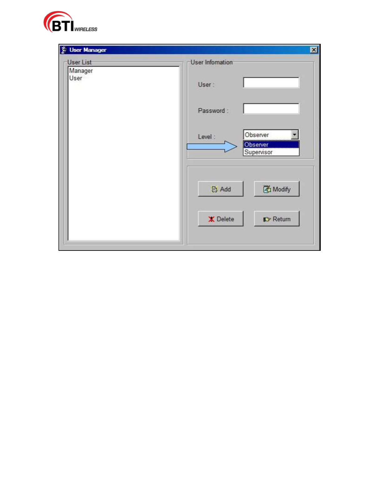
mBSC-H DAS System
Installation Manual Issue 7
© 2009-2014, BTI Wireless Page 61
Observer: This level is a monitoring functionality only. This level is most commonly used for users
who will monitor the system and review alarm logs. At the Observer level, a user may only: modify
their user name and password and; view, save and print Alarm information.Figure 4-44. Select a
User Level
2. Enter a user name and password, Figure 4-45. Then click Add.
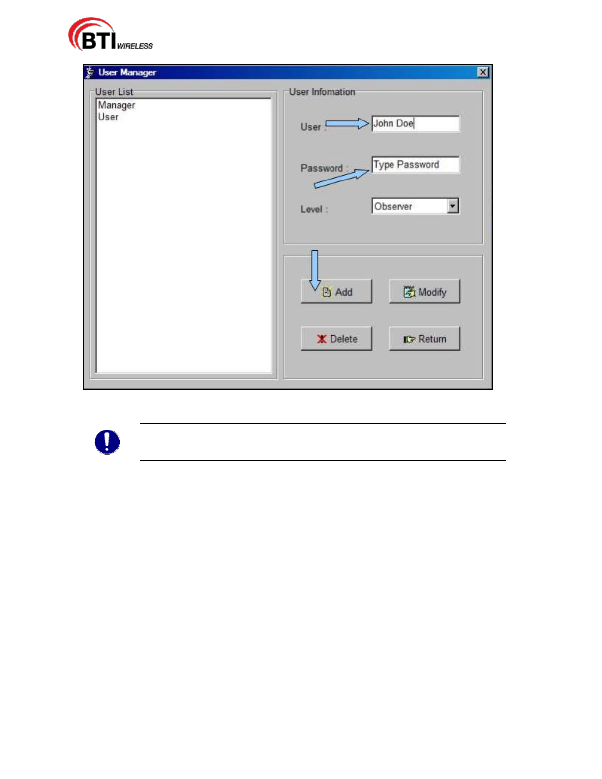
mBSC-H DAS System
Installation Manual Issue 7
© 2009-2014, BTI Wireless Page 62
Figure 4-45. Enter User name and Password
Note: There is a limit of 20 Alpha-Numeric characters for both User name and
password entries. User names are selectable from the Login screen drop down
menu, once entered into the system. Passwords are case sensitive.
3. Additional detailed information for managing User accounts, including deleting and modifying User
accounts is contained in the NMS User Manual.
4.4.6.3 Configure Software Parameters
The NMS system software parameter defaults allow the user to focus less on configuring the software
system , Figure 4-46, and more on the critical functionality for the DAS system. The NMS is designed to
run in a background mode when the SNMP option is activated. The background mode allows constant
communication with the NOC while leaving the user's device accessible. The NMS icon resides in the Icon
Tray in the status bar of the user's device.
Detailed parameter information is available in the NMS User Manual.
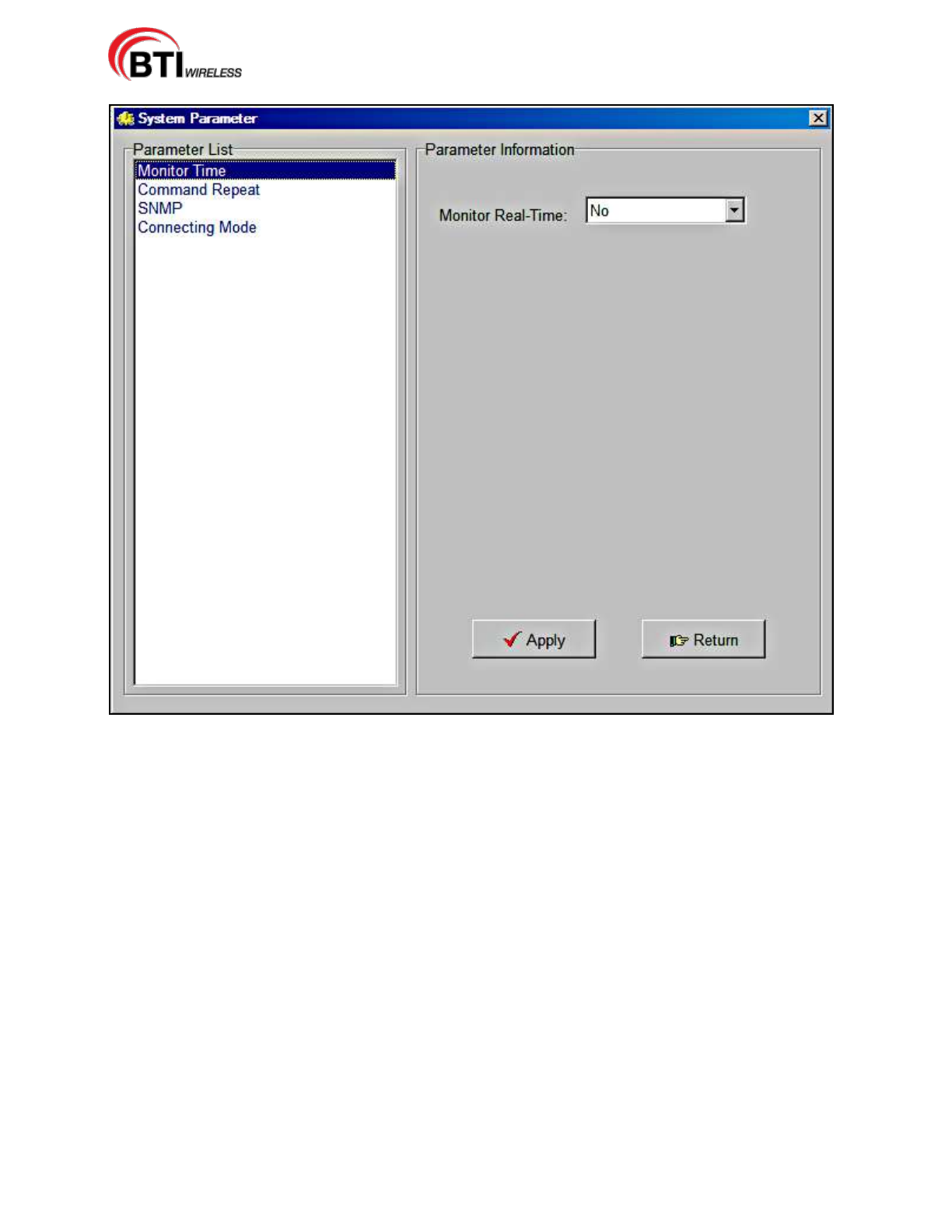
mBSC-H DAS System
Installation Manual Issue 7
© 2009-2014, BTI Wireless Page 63
Figure 4-46. System Parameter Screen
4.4.7 Firmware Update
DAS components periodically require firmware updates. The following list of components may require
periodic firmware updates:
BIU
FIU
PA
RCU
Remote Unit
A notification email is sent with the firmware update attached as a file to the email. The following
procedures detail the firmware update process:
1. Verify the email is genuine and the file attachment is safe for download. The sent file will be named in
the following manner and have a file extension of .s:
DAS8345_[Component]_[Version].s
2. Download the attached file to any chosen folder or the desktop. Note the folder name, if saved to a
designated folder.
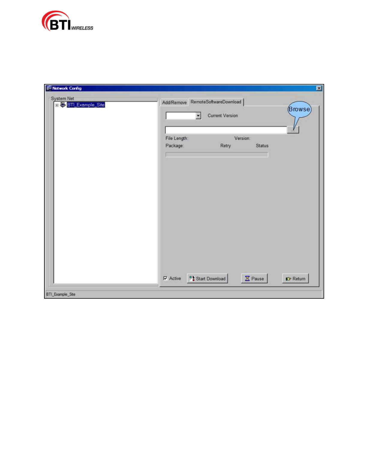
mBSC-H DAS System
Installation Manual Issue 7
© 2009-2014, BTI Wireless Page 64
3. Log into the NMS System.
4. Click on NetConfig
5. Using the RemoteSoftwareDownload interface, Figure 4-47, Locate the file by clicking on the browse
button.
Figure 4-47. Remote Software Download Screen
6. Click Start Download. The firmware update may be paused if needed by clicking the Pause button.
7. Once the download is complete, click Return.
4.4.8 Software Upgrade Installation
4.4.8.1 CD-ROM Install
The CD-ROM Upgrade install is a quick and simple installation. Use the following procedure to install the
application on to the computer:
1. Check that no instance of NMS is running.
2. Open the CD drive on the machine.
3. Place the CD into the drive and close the drive.
4. The CD will begin the install wizard and ask if the user would like to overwrite the older NMS version,
Figure 4-48.
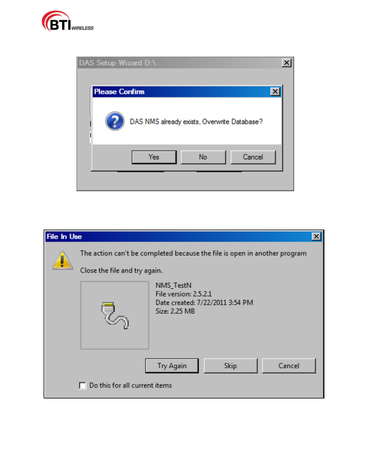
mBSC-H DAS System
Installation Manual Issue 7
© 2009-2014, BTI Wireless Page 65
5. Select Yes.
Figure 4-48. Replace NMS File
1. An error dialog box will appear, Figure 4-49, if the older version of NMS is open and running.
2. Close NMS and click Try Again.
Figure 4-49. NMS Update Fail Error Box
4.4.9 NMS Upgrade Installation Review

mBSC-H DAS System
Installation Manual Issue 7
© 2009-2014, BTI Wireless Page 66
Table 4-13. NMS Initial Installation Checklist
Items
Description
1
Verify that the CD is undamaged and the server software is installed.
2
Confirm that the version number once the set-up Wizard launches NMS.
3
Verify that the shortcut launches the NMS Login.
4
Check that the default Manager Account and password have been updated.
5
Confirm that new User accounts and passwords have been added.
Table 4-14. NMS Firmware Update and Software Upgrade Checklist
Items
Description
1
Verify that the email and attachment. are genuine.
2
Confirm that the firmware update is downloaded to the appropriate folder on the
computer.
3
Verify that firmware update was complete from the RemoteSoftwareDownload interface.
4
Confirm that no instance of NMS is running before beginning Upgrade installation.
5
Check the version number to verify upgrade once the set-up Wizard has launched NMS.
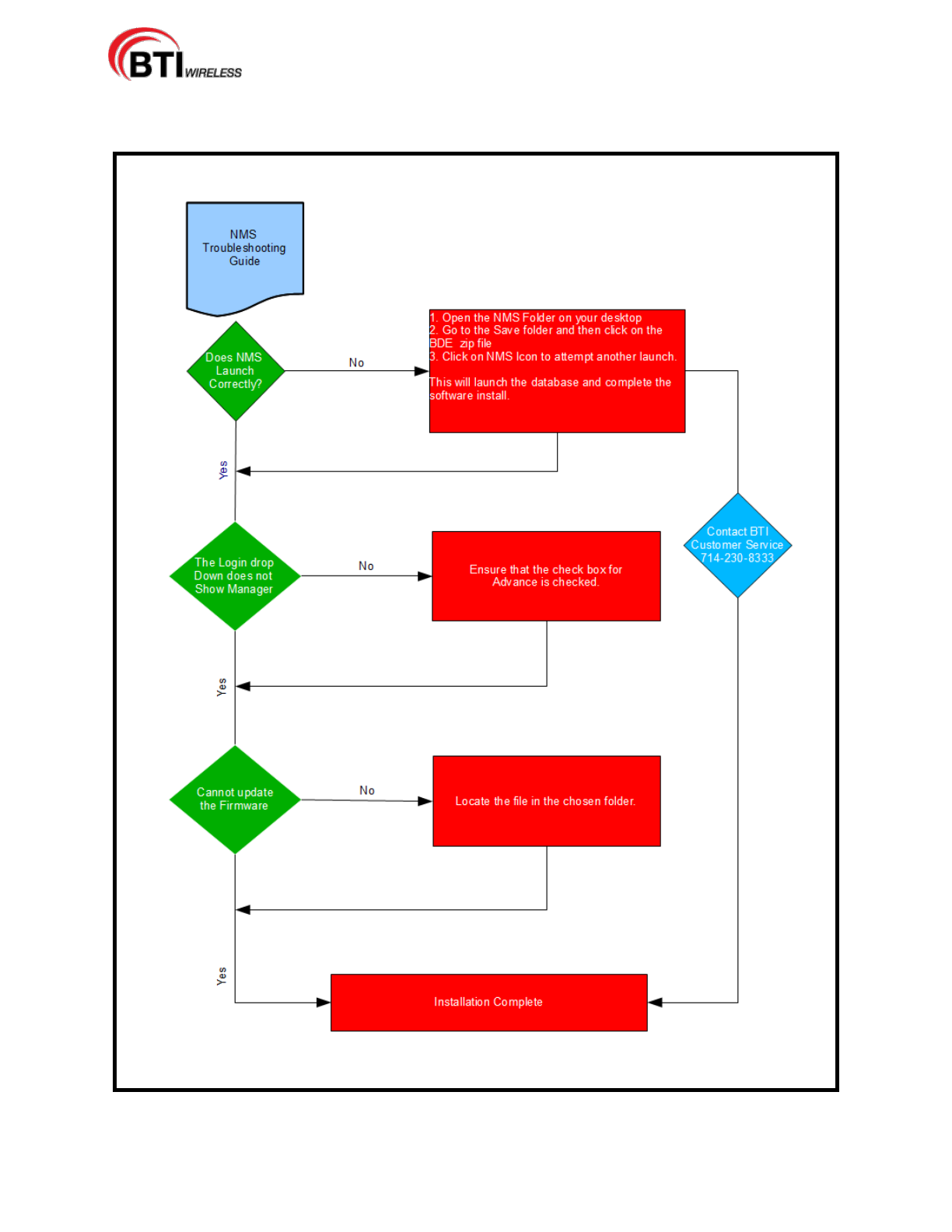
mBSC-H DAS System
Installation Manual Issue 7
© 2009-2014, BTI Wireless Page 67
4.4.10 Troubleshooting
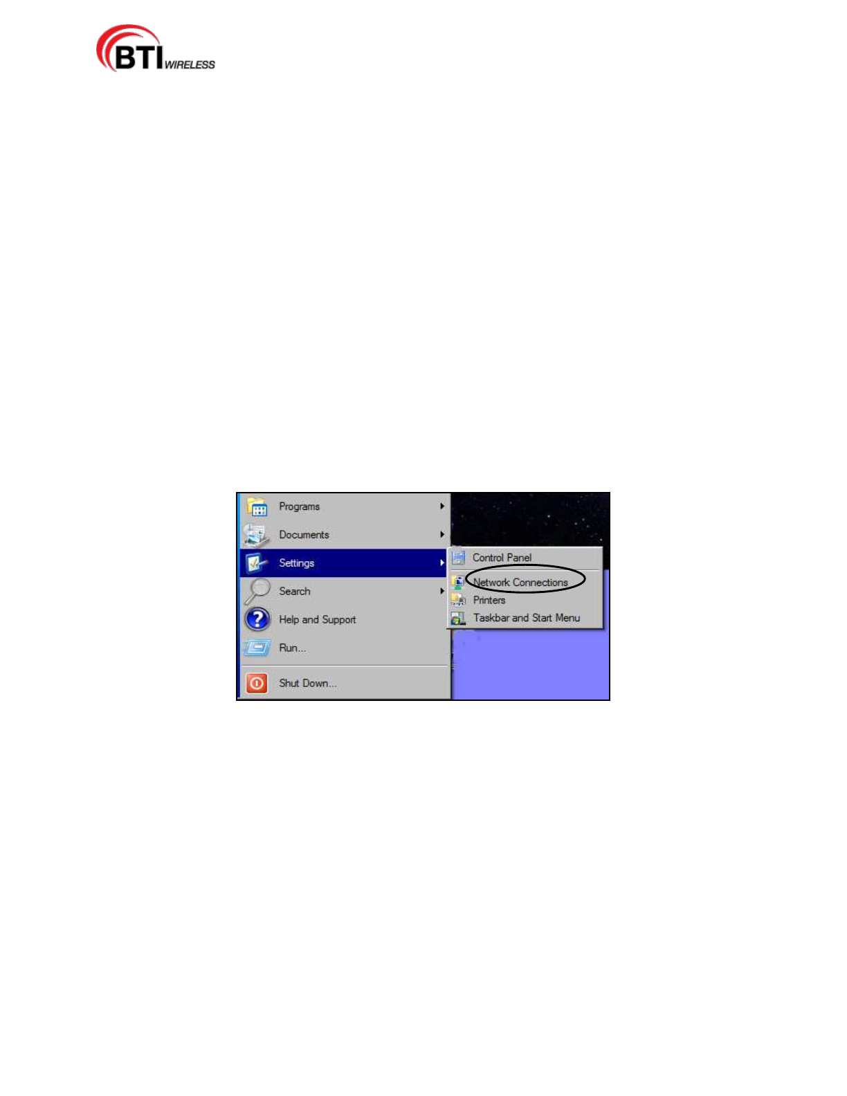
mBSC-H DAS System
Installation Manual Issue 7
© 2009-2014, BTI Wireless Page 68
5 mBSC DAS SYSTEM START-UP
When the system component installations are complete, the system must be configured. Please refer to
the applicable System Operation and User Manual for detailed system configurations, operations, and
troubleshooting/test procedures
5.1 SYSTEM COMMUNICATION
Once the components have been installed, the system should be activated by establishing communication
through the Host Unit and configuring the system to the network through the NMS.
5.1.1 Establishing a Host Unit communication
The Host Unit hardware default IP address must be updated with the customer's network IP address. This
is accomplished by first establishing a communication link, setting up the initial base system and
configuring the IP Address parameter. Use the following procedure to establish communication with the
Host Unit :
1. Connect the NMS installed Laptop ethernet port to the RCU front ethernet port with a cross or null
modem cable.
2. From the Laptop, click the Start Button, then Settings and Network Connections, Figure 5-1.
Figure 5-1. Open Network Connections
3. Select the LAN Icon and click on File then Properties, Figure 5-2.

mBSC-H DAS System
Installation Manual Issue 7
© 2009-2014, BTI Wireless Page 69
Figure 5-2. LAN Properties
4. Click on Internet Version Protocol (TCP/IPv4) and then click on Properties, Figure 5-3.
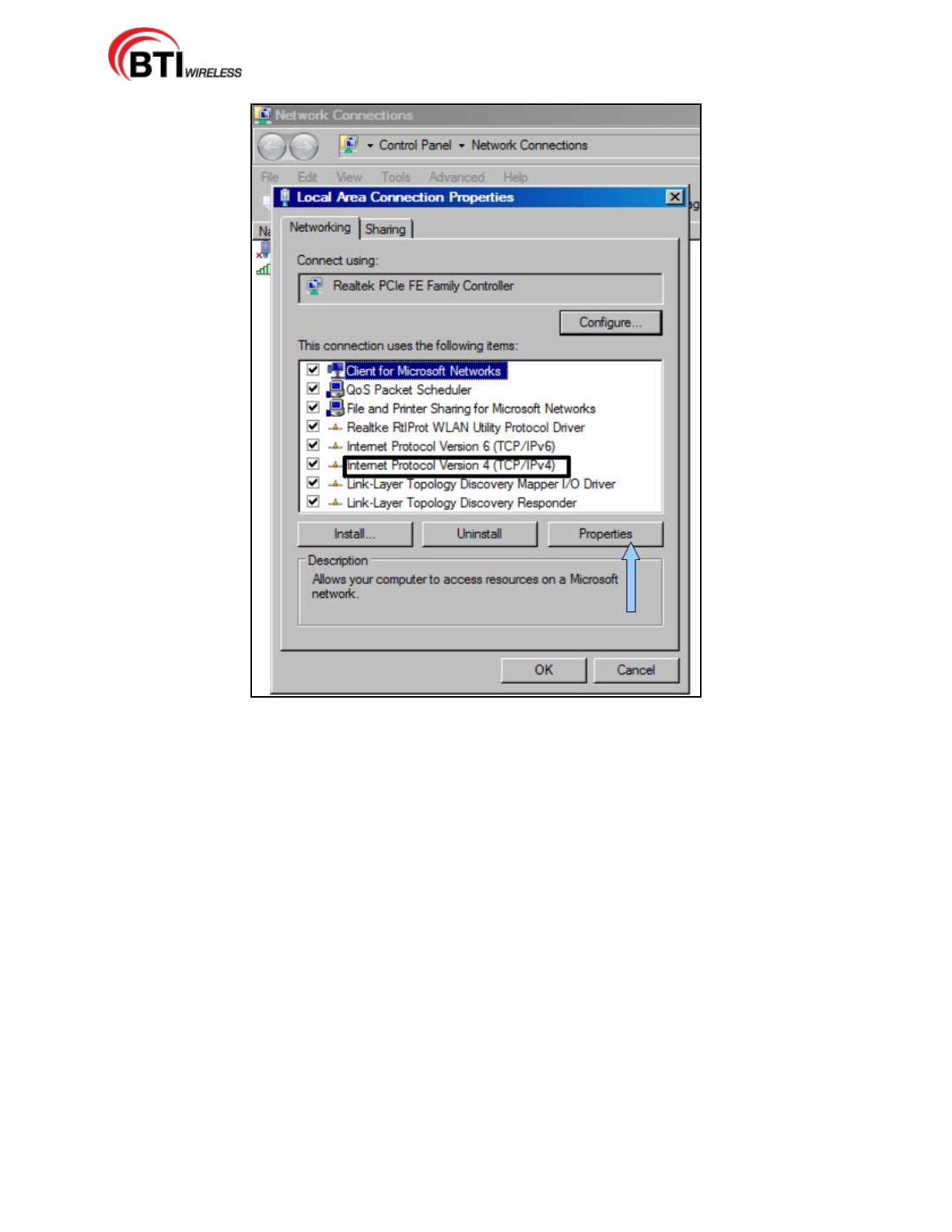
mBSC-H DAS System
Installation Manual Issue 7
© 2009-2014, BTI Wireless Page 70
Figure 5-3. Select Internet Protocol Version 4
5. Click on the second option, Use the Following IP Address:, Figure 5-4, and manually enter the IP
Address: 128.0.2.30. The Subnet mask will automatically default to 255.255.0.0.
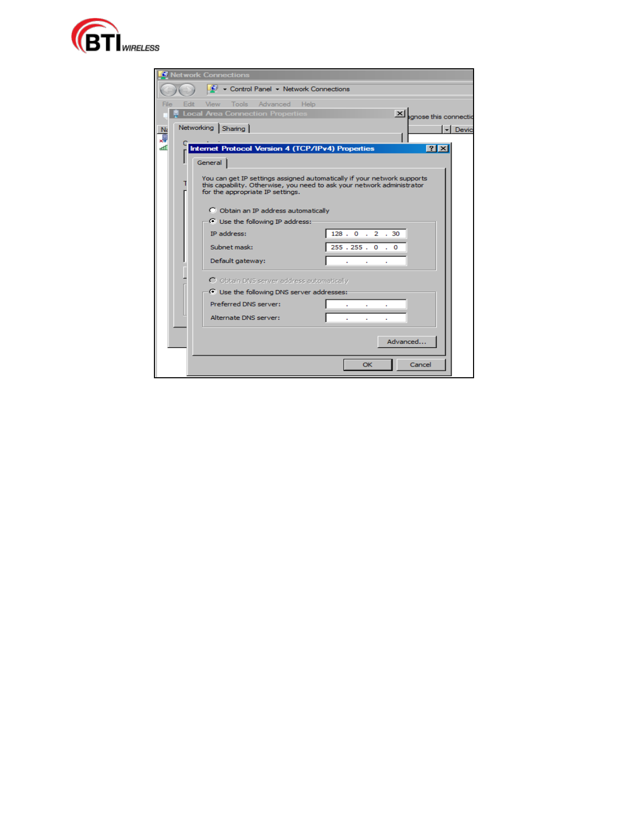
mBSC-H DAS System
Installation Manual Issue 7
© 2009-2014, BTI Wireless Page 71
Figure 5-4. Manually Enter the IP Address
6. Click OK.
5.2 INITIAL NETWORK CONFIGURATION
Once installed and software configurations are complete, the network must be configured and activated.
The first half of this section details the initial functions necessary for a basic system activation through the
NMS. The second half details in-depth information for network system parameters. Access to the DAS
system configuration Net Config Manager is through the Network(N) menu bar drop-down or the Net
Config Command bar button, Figure 5-5, the ALT key + (N) or the Netconfig Icon on the Command bar.
The DAS Net Config Manager includes the ability to access the following functions:
Add/Modify/Delete Sites
Add/Modify/Delete the Host Unit(s)
Add/Modify/Delete the Remote Unit(s)
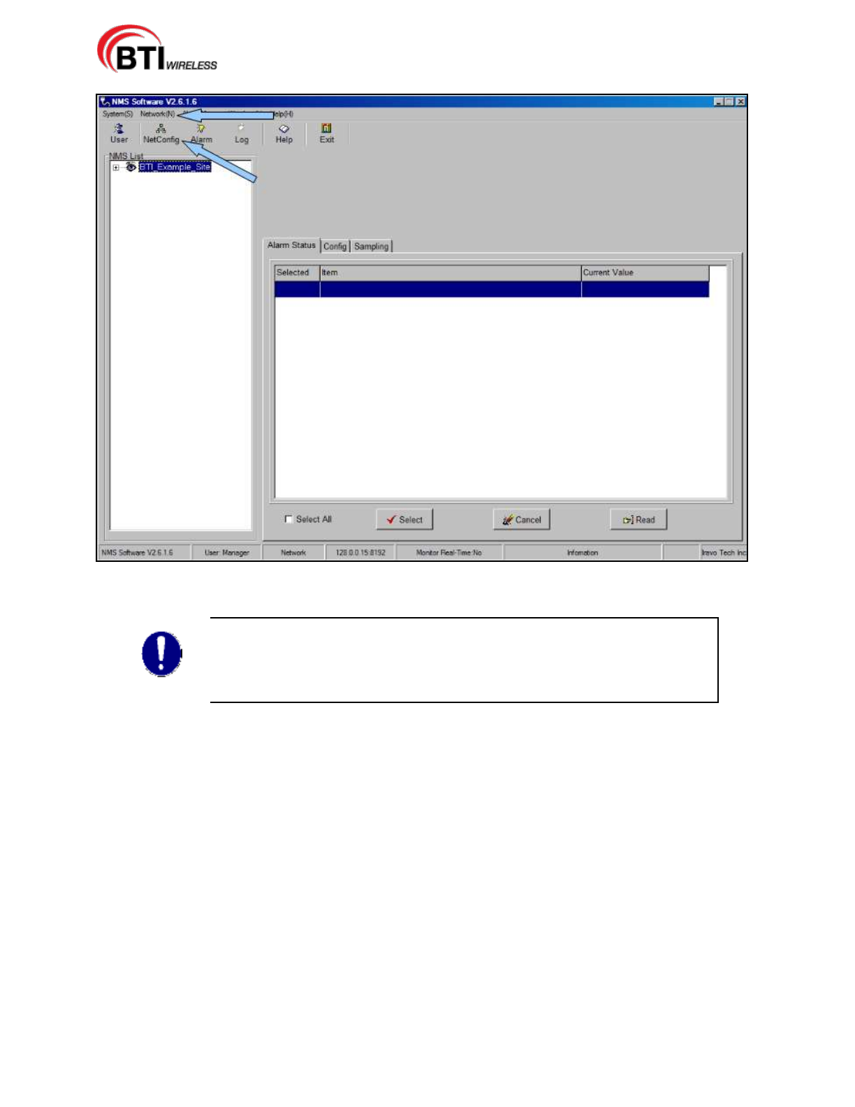
mBSC-H DAS System
Installation Manual Issue 7
© 2009-2014, BTI Wireless Page 72
Figure 5-5. Accessing the Network Configuration screen
The NMS software provides an example configuration as shown in Figures 5-5
and 5-6. The example may be deleted or the example information may be
overwritten with customer specific information and then saved by clicking the
Modify button. For the purposes of this installation manual, the example has
been deleted to provide the most accurate details.
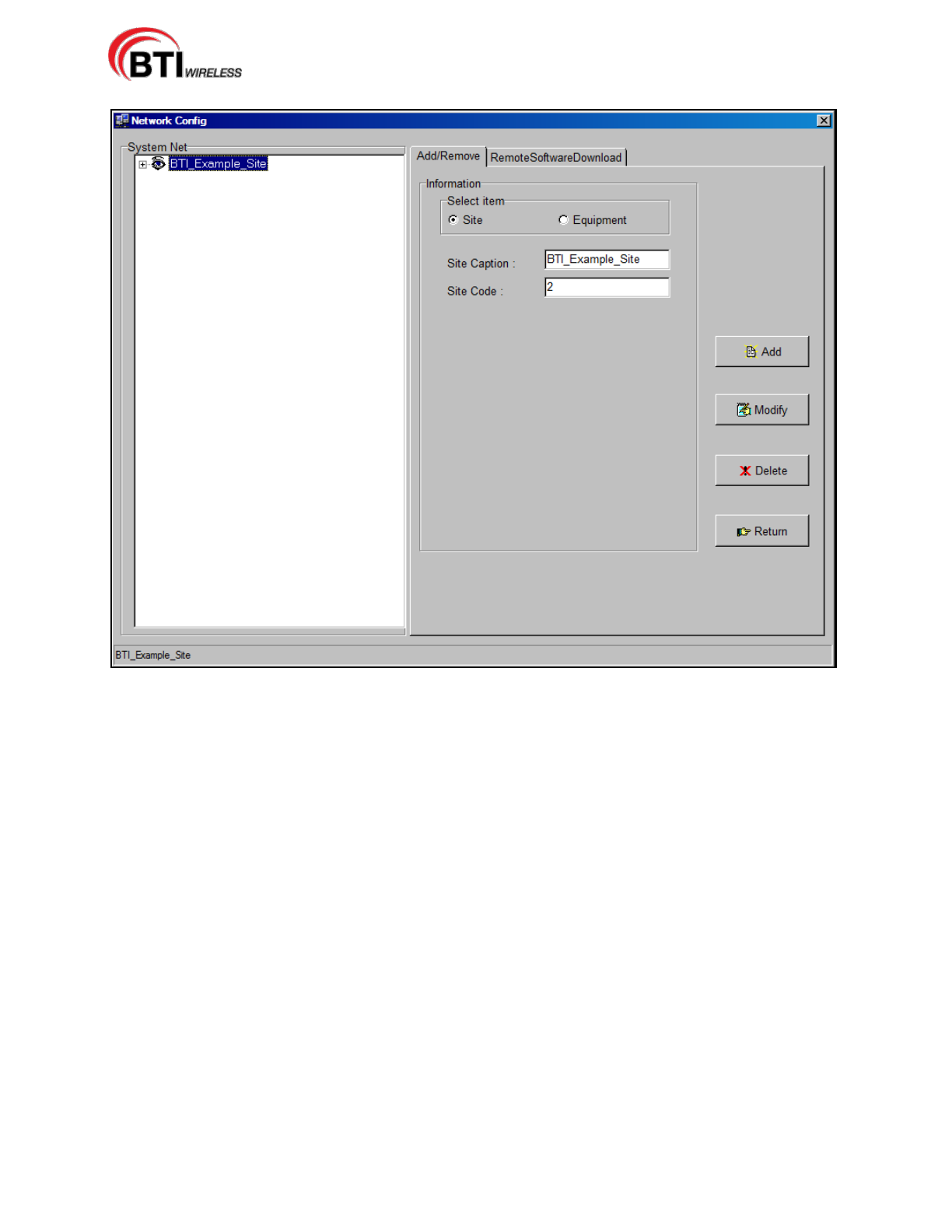
mBSC-H DAS System
Installation Manual Issue 7
© 2009-2014, BTI Wireless Page 73
Figure 5-6. BTI Example System Configuration
5.2.1 Add a Site
The highest level of system configuration is defined by adding a Site Caption and a Site Code. The Site
Caption alpha-numeric text field accepts any user-defined descriptive name (30 alpha-numeric character
limit) and the Site Code accepts integer values only (1 through 9999 numeric limit). The following steps are
used to add the Site Caption and Site Code:
1. Access the Network Config screen, Figure 5-5, via the NetConfig Icon on the Command bar, using ALT
+ (N) or the Network(N) menu drop-down.
2. Click on the Site button in the Select Information field,, Figure 5-7.
3. Enter the Site Caption (Customer defined Site Name) and the Site Code (Customer defined Site
Number). The example, BTI_Example_Cypress_Site is shown in Figure 5-8.
4. Click Add to save the Site Caption and Site Code.
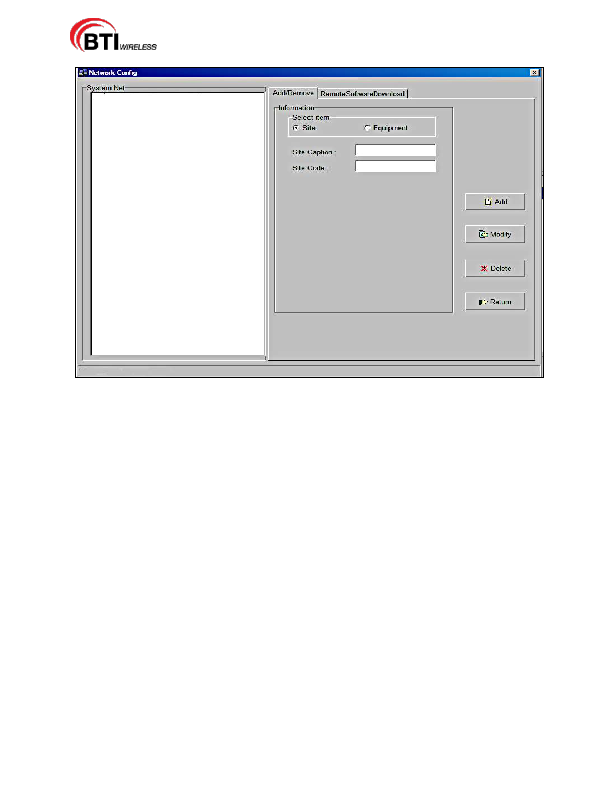
mBSC-H DAS System
Installation Manual Issue 7
© 2009-2014, BTI Wireless Page 74
Figure 5-7. Add a Site
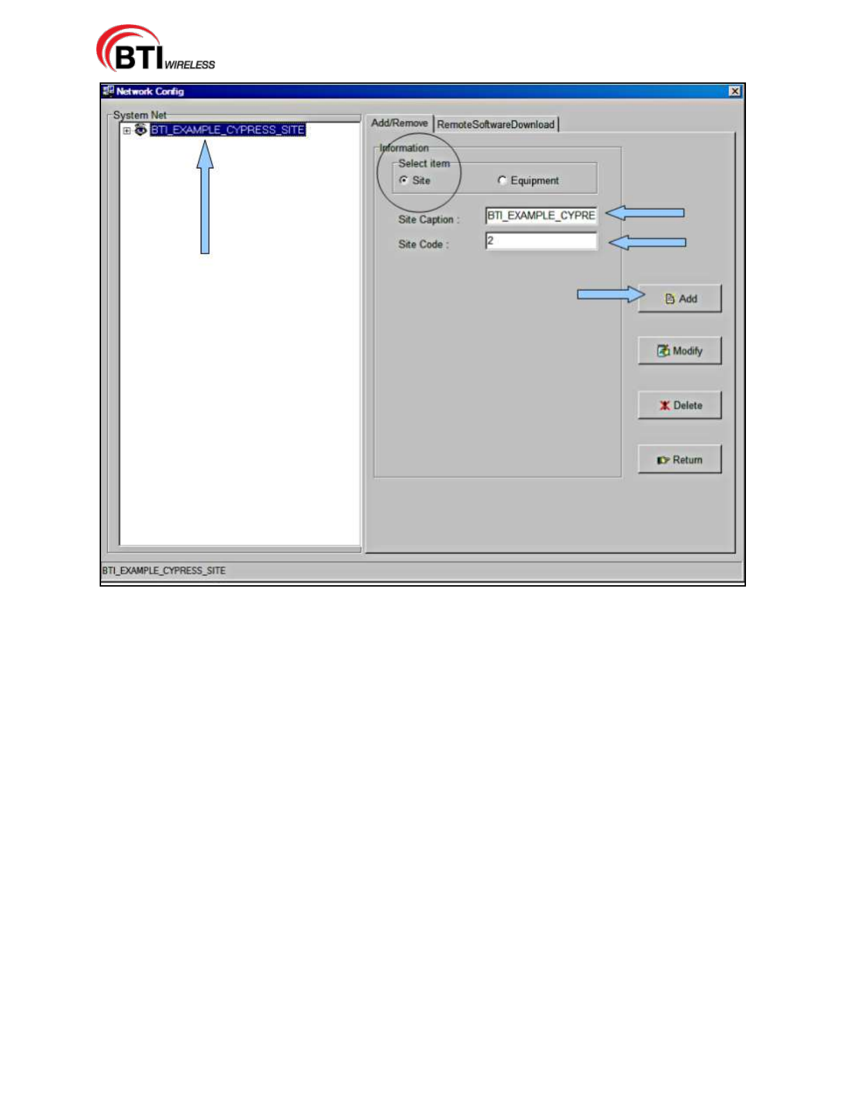
mBSC-H DAS System
Installation Manual Issue 7
© 2009-2014, BTI Wireless Page 75
Figure 5-8 Adding a Site
5.2.2 Add a Host Unit
Once the Site Caption and Site Code have been configured, the Host Unit should be added to the system.
The HU Caption alpha-numeric text field accepts any user-defined descriptive HU Caption (20
alpha-numeric character limit) and HU No. accepts integer values only (1 through 9999 numeric limit). The
following steps provide the Host Unit configuration:
1. Click on Equipment to bring up the new information section for the DAS System equipment.
2. Click on HU in the Select Equipment section. Verify that the Site Caption and Site Code are correct for
the Host Unit being added.
3. Add the customer designated HU Caption and HU No. as shown in Figure 5-9.
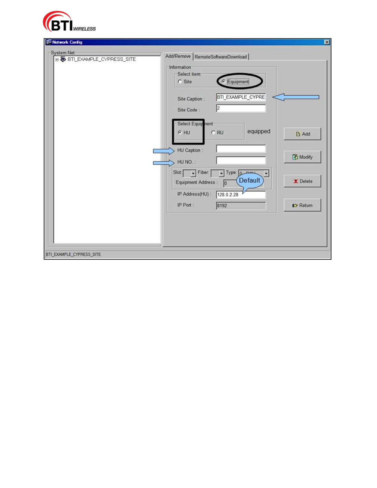
mBSC-H DAS System
Installation Manual Issue 7
© 2009-2014, BTI Wireless Page 76
Figure 5-9. Adding a Host Unit
4. Verify that all changes have been correctly entered and click Add, Figure 5-10.
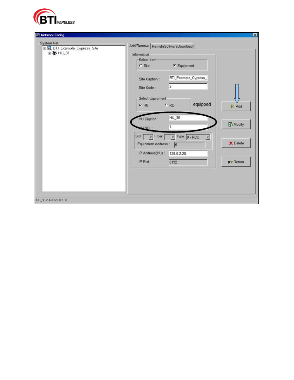
mBSC-H DAS System
Installation Manual Issue 7
© 2009-2014, BTI Wireless Page 77
Figure 5-10. Configured Host Unit
5.2.3 Configuring the Host Unit Hardware Card
Once the Host Unit has been added to the system, the IP address for the Host Unit must be changed from
the default to the designated network IP address in the Host Unit Hardware Card. Configuring the IP
Address is done from the Main Command Screen. The following procedures outline the steps necessary to
change the Host Unit IP Address:
1. From the Main Command Screen, Select the added HU.
2. Select the RCU Module, Figure 5-11.
3. Then click on the Config tab.
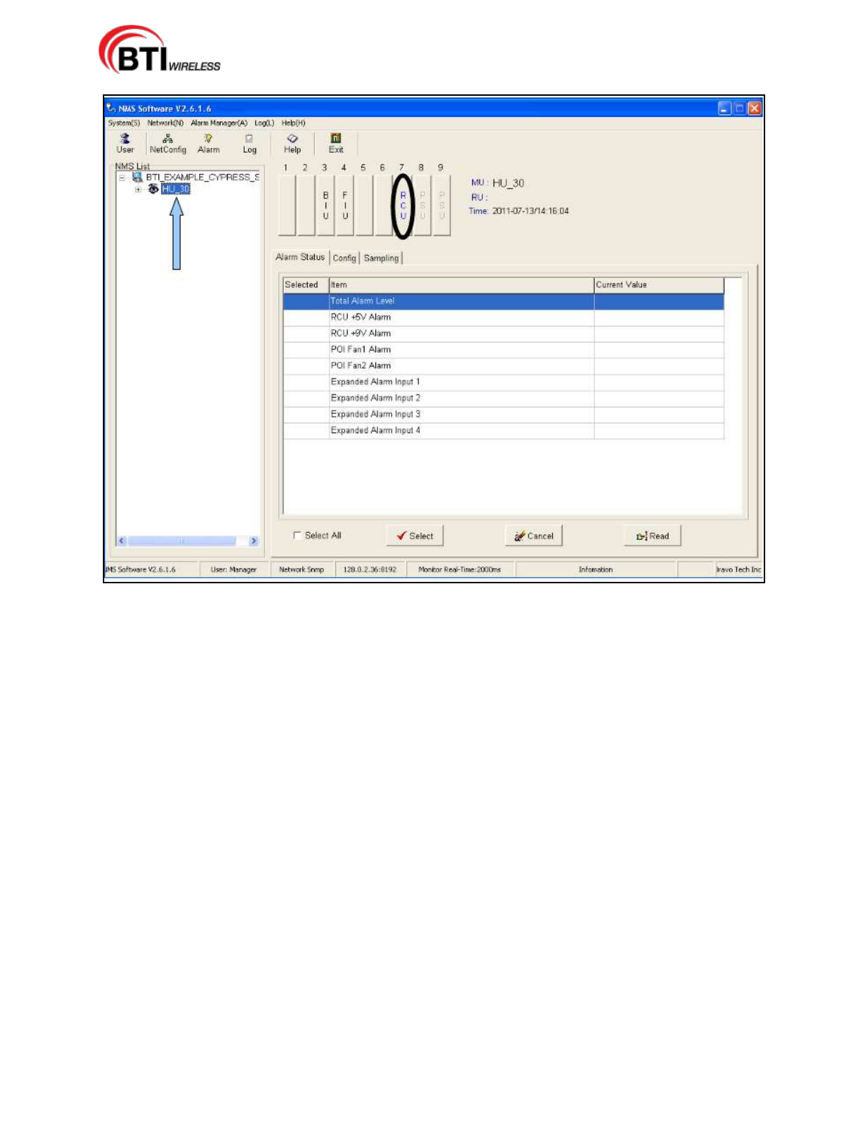
mBSC-H DAS System
Installation Manual Issue 7
© 2009-2014, BTI Wireless Page 78
Figure 5-11. Select the HU
4. Click on Parameter List. Then click Select All.
5. Click on Read, Figure 5-12.
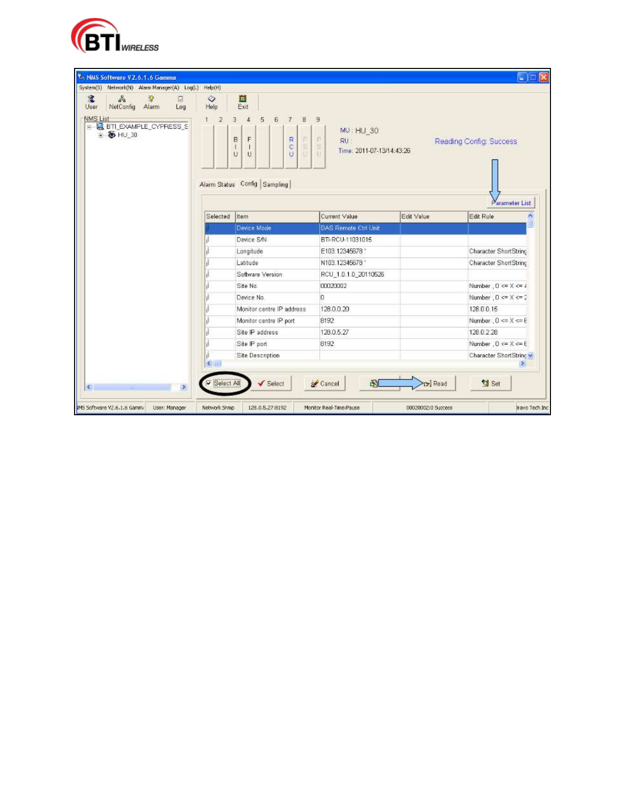
mBSC-H DAS System
Installation Manual Issue 7
© 2009-2014, BTI Wireless Page 79
Figure 5-12. View the Current Values
6. Confirm Select All is unchecked. Click on Site IP Address in the Parameter List.
7. Click Edit.
8. Enter the new IP Address in the Edit Value Column, Figure 5-13.
9. Click Set, Figure 5-14.
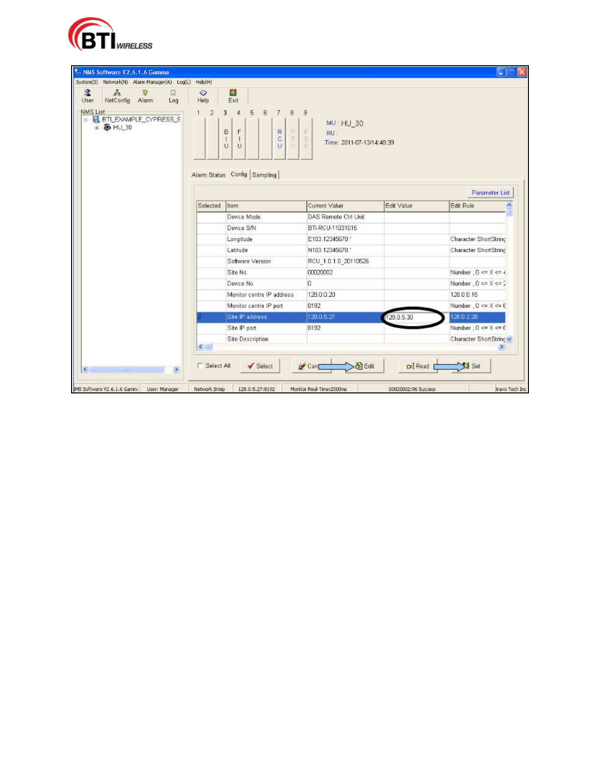
mBSC-H DAS System
Installation Manual Issue 7
© 2009-2014, BTI Wireless Page 80
Figure 5-13. Enter the New IP Address
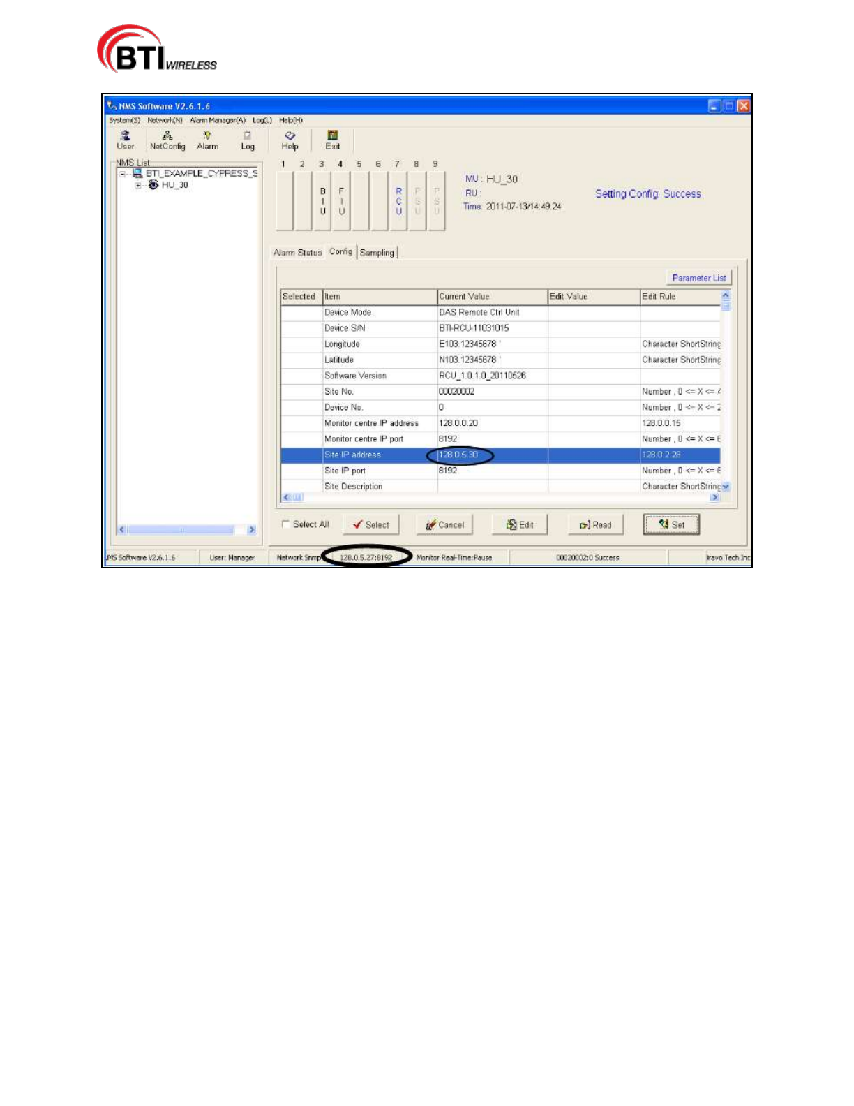
mBSC-H DAS System
Installation Manual Issue 7
© 2009-2014, BTI Wireless Page 81
Figure 5-14. IP Address Update Setting
5.2.4 Map the IP Address to the NMS Software
1. Click the Netconfig button.
2. Select the Host Unit. Figure 5-15.
3. Change the IP Address(HU) from the default value to the designated network IP address. This will map
the IP Address in the NMS System to the HU hardware card.
4. Then Click Modify. Click Return
5. Restart NMS to set the new parameters.
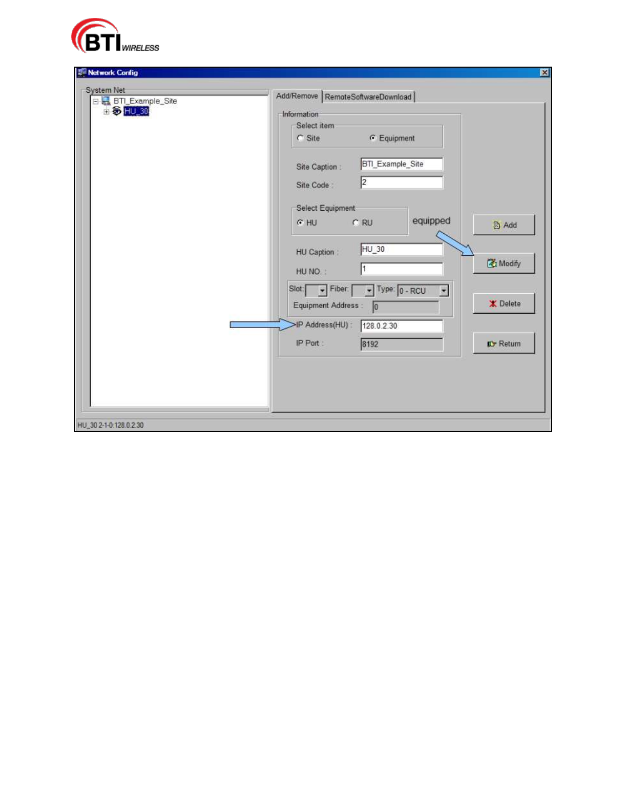
mBSC-H DAS System
Installation Manual Issue 7
© 2009-2014, BTI Wireless Page 82
Figure 5-15. Modify IP Address(HU)
From the Main Command Screen:
1. Select the updated Host Unit.
2. Click on Parameter List. Then click Select All.
3. Click on Read, Figure 5-16.
4. Confirm that the HU Hardware Card IP Address matches.
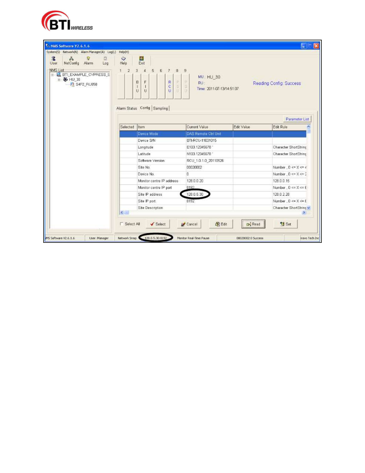
mBSC-H DAS System
Installation Manual Issue 7
© 2009-2014, BTI Wireless Page 83
Figure 5-16. Confirm IP Address Update Accepted.
5.2.5 Adding a Master and/or a Slave Remote Unit
Once the Site Caption, Site Code, and Host Unit have been configured, the Master Remote Unit should be
added to the system first, followed by any Slave Remote Units. The RU Caption alpha-numeric text field
accepts the default RU Caption or any user-defined descriptive RU Caption (20 alpha-numeric character
limit) and the RU No. field accepts integer values only (1 through 9999 numeric limit). NMS creates a
default name using a combination of representative letters and numbers in the following format:
S#F#_MRU###(#)
[Slot#][Fiber # designation]_[MasterRU][Frequency]
The example in Illustration 5-17, S4F2_MRU850 shows the default name with an M designator for
Master.
S#F#_SRU###(#)
[Slot#][Fiber designation]_[SlaveRU][Frequency]
The example in Illustration 5-18, S4F2_SRU1900 shows the default name with an S designator for Slave.
5.2.5.1 Adding a Remote Unit
Use the following steps to define the Remote Unit configuration:
1. Click on the new HU in the System Net section.
2. Click on Equipment to bring up the new information section for the DAS System equipment.
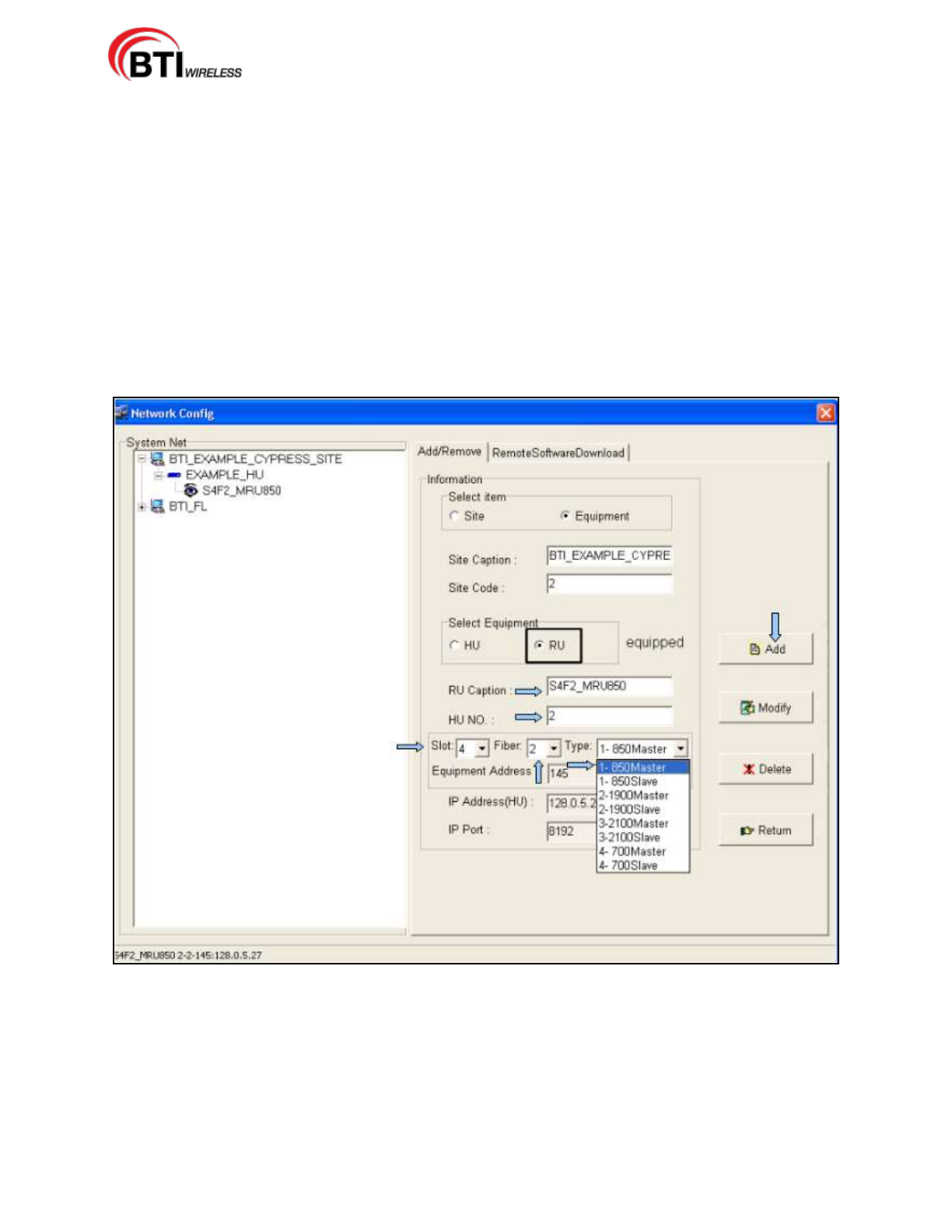
mBSC-H DAS System
Installation Manual Issue 7
© 2009-2014, BTI Wireless Page 84
3. Click on RU in the Select Equipment section.
4. Select the Slot No. for the Remote Unit. Use Table 6-1 as a guide for determining the Slot, Fiber and
Type selections.
5. Select the Fiber value.
6. Select the Type of Remote Unit. Selecting the Type of Unit also designates the Master or Slave
configuration.
7. NMS creates a default name based on the chosen slot, fiber and type values selected as shown in
Illustration 6-13 and Illustration 6-14. The default name may be deleted and may be replaced with a
customer designated name as the RU Caption, if desired.
8. Verify that the Site Caption, Site Code and HU No. are correct for the Remote Unit being added
9. Click Add.
Figure 5-17 Adding Master Remote Unit
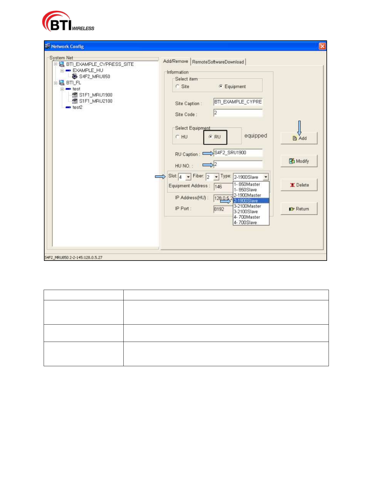
mBSC-H DAS System
Installation Manual Issue 7
© 2009-2014, BTI Wireless Page 85
Figure 5-18. Adding a Slave Remote Unit
Table 5-2. Slots, Fiber and Type Values
Name
Configuration Value
Slot
Represents the slots on the HU from Left to Right that can be assigned to
various equipment. Slots 1-6 are reserved for the FIU and BIU. Designating
a slot number maps the RU to an FIU.
Fiber
Maps the RU to the Fiber connection on the Host Unit to the associated
FIU.
Type
Defines the frequency used and must match the RU type installed. There
are currently four different types of Remote Units. 700 MHz, 850 MHz, 1900
MHz, and 2100 MHz.
5.2.5.2 Modifying or Deleting a Remote Unit
Use the following steps to modify or delete a Remote Unit:
1. Select the Remote Unit from the System Net section.
2. To delete the Remote Unit, click Delete.
3. To modify the Remote Unit, enter the changes desired and press Modify. The Remote Unit caption,
Slot, Fiber and Type may be changed using the Modify button.
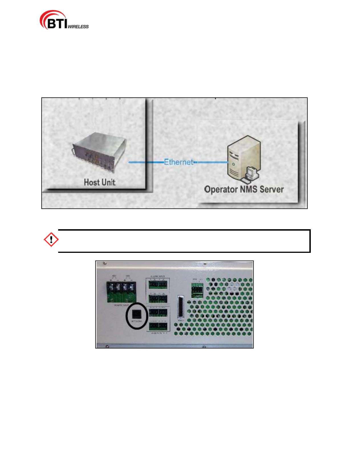
mBSC-H DAS System
Installation Manual Issue 7
© 2009-2014, BTI Wireless Page 86
5.2.6 Connect Host Unit to Server
With the IP address updated, the Host Unit must be connected the server, Figure 5-19, for communication
information to function. The Host Unit is connected from the Network port on the back interface through the
hub to the server as shown in Figure 5-20 or may be directly connected from the back interface port to the
server. The Host Unit may also be connected to the server from the RCU network port on the front
interface, either directly or through the hub to the server. Only one network port connection may be used at
a time.
Figure 19. Connect Host Unit to Server
Only one port may be connected to the server at a time, as both front interface and back
interface network ports are the same port.
Figure 5-20. HU Back Interface Network Connection
5.3 MANAGING AND MONITORING ALARMS
5.3.1 Alarm Manager
The NMS is also the means for managing and monitoring the DAS systems through the Alarm Manager(A)
menu or the Alarm Icon on the Menu bar. The managing and monitoring of the DAS system is more
completely detailed in the BTI NMS User Manual.
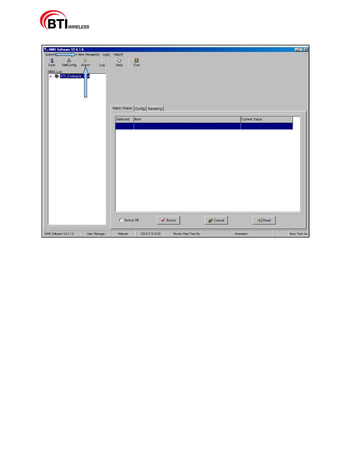
mBSC-H DAS System
Installation Manual Issue 7
© 2009-2014, BTI Wireless Page 87
Figure 5-21. Alarm Manager
5.3.2 Configuring Standard Alarm Defaults
Configuring NMS is easily accomplished through the Custom Alarm tab, Figure 5-21. Select the alarm
type and click the Select button for the appropriate category. Table 5-3 provides a recommended list of
alarms by category that may be selected to create a custom alarm configuration.
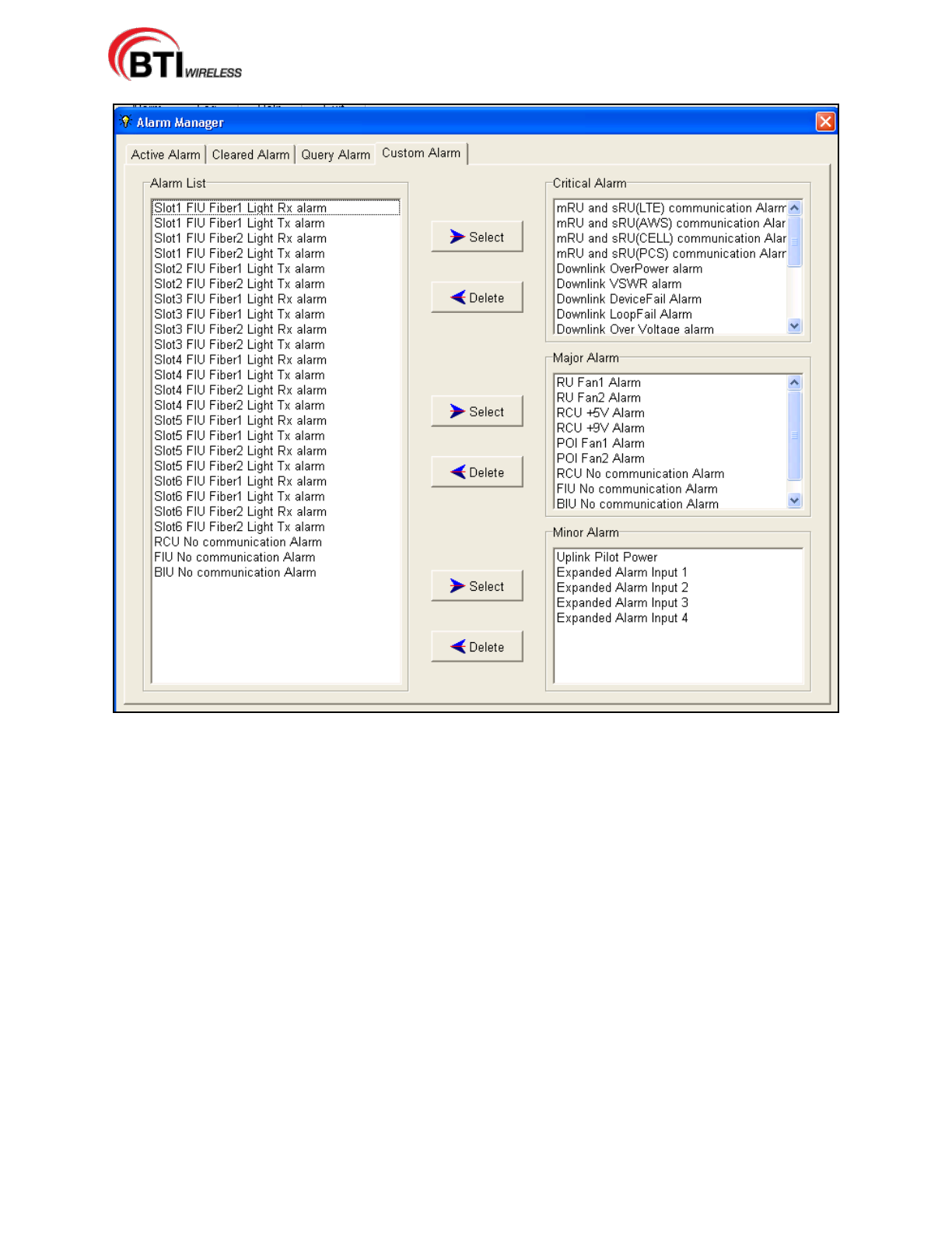
mBSC-H DAS System
Installation Manual Issue 7
© 2009-2014, BTI Wireless Page 88
Figure 5-22. Configuring Custom Alarm Levels
Figure 5-23 shows an active alarm.
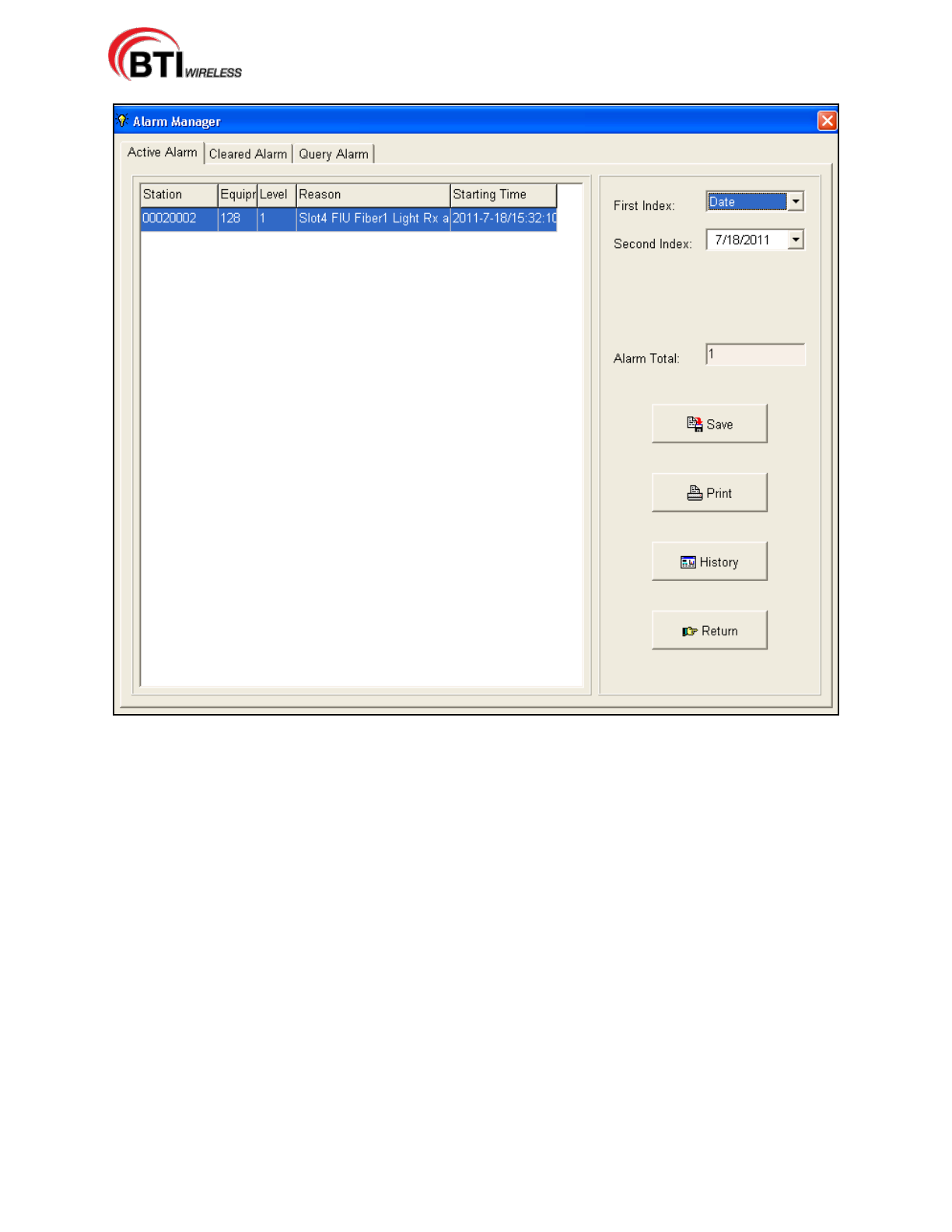
mBSC-H DAS System
Installation Manual Issue 7
© 2009-2014, BTI Wireless Page 89
Figure 5-23. Active Alarm Screen
The Table5-3 provides alarm indicator descriptions for the mBSC DAS system. Alarm types for the Host
Unit and Remote Unit monitored by the NMS are included as well as optional components such as the
POI. The recommended category for the alarm indicator is included in column 3 of the table along with the
affected component. Critical alarms indicate system failures that disable the uplink or downlink operation.
Other categories, such as Major, may indicate impaired performance, but not the catastrophic system
failure or a specific RU node failure.

mBSC-H DAS System
Installation Manual Issue 7
© 2009-2014, BTI Wireless Page 90
Table 5-3. Host Unit Alarm Indicators by Category
Alarm Indicator
Description
Category
Component
Downlink Function
Alarm
Downlink overvoltage or
component issue
Critical
PA
Downlink OverPower
Transmit Power exceeds rated
output
Critical
PA
Downlink
OverTemperature
MCPA is operating at an unsafe
temperature
Critical
PA (Fiber Module)
Downlink VSWR
Antenna system VSWR
exceeds preset level
Critical
PA
Fiber Light Rx
RU fiber RX failure
Critical
Remote Unit
Fiber Light Tx
RU fiber TX failure
Critical
Remote Unit
Fiber1 Light RX
FIU Fiber1 port RX light fail
Critical
Host Unit FIU
Fiber1 Light TX
FIU Fiber1 port TX light fail
Critical
Host Unit FIU
Fiber2 Light RX
FIU Fiber2 port RX light fail
Critical
Host Unit FIU
Fiber2 Light TX
FIU Fiber2 port TX light fail
Critical
Host Unit FIU
mRU and sRU1
comm
Master to Slave
communications failed
Critical
Remote Unit
mRU and sRU2
comm
Master to Slave
communications failed
Critical
Remote Unit
Uplink Alarm
RU Receive LNA failure
Critical
Remote Unit
BIU No
Communication
BIU to RCU comm failure
Major
Host Unit
FIU No
Communication
FIU to RCU comm failure
Major
Host Unit
POI Fan1
POI Fan1 failure
Major
Host Unit POI
POI Fan2
POI Fan2 failure
Major
Host Unit POI
RCU +5V
Host Unit RCU power supply
alarm
Major
Host Unit RCU
RCU +9V
Host Unit RCU power supply
alarm
Major
Host Unit RCU
RCU No
Communication
NMS to RCU comm failure
Major
Host Unit
RU Control Alarm
RU Internal PA to CPU comm
failure
Major
Remote Unit
RU Fan1
RU Fan failure
Major
Remote Unit
RU Fan2
RU Fan failure
Major
Remote Unit
Uplink Pilot Power
Uplink Pilot Power Failure
Minor
Remote Unit
Expanded Alarm
Input 1
Expansion
User Defined
Third Party
Component
Expanded Alarm
Input 2
Expansion
User Defined
Third Party
Component
Expanded Alarm
Input 3
Expansion
User Defined
Third Party
Component
Expanded Alarm
Input 4
Expansion
User Defined
Third Party
Component

mBSC-H DAS System
Installation Manual Issue 7
© 2009-2014, BTI Wireless Page 91
5.3.3 System Activation Review
Table 5-4. System Start-up Review
Items
Description
1
Verify that the Host Unit communication was established.
2
Confirm that at least one Site has been added.
3
Verify that the Host Unit Hardware card IP address has been configured.
4
Check that the Remote Unit is communicating with the Host Unit
5
Confirm that the Host Unit is connected to the Server.
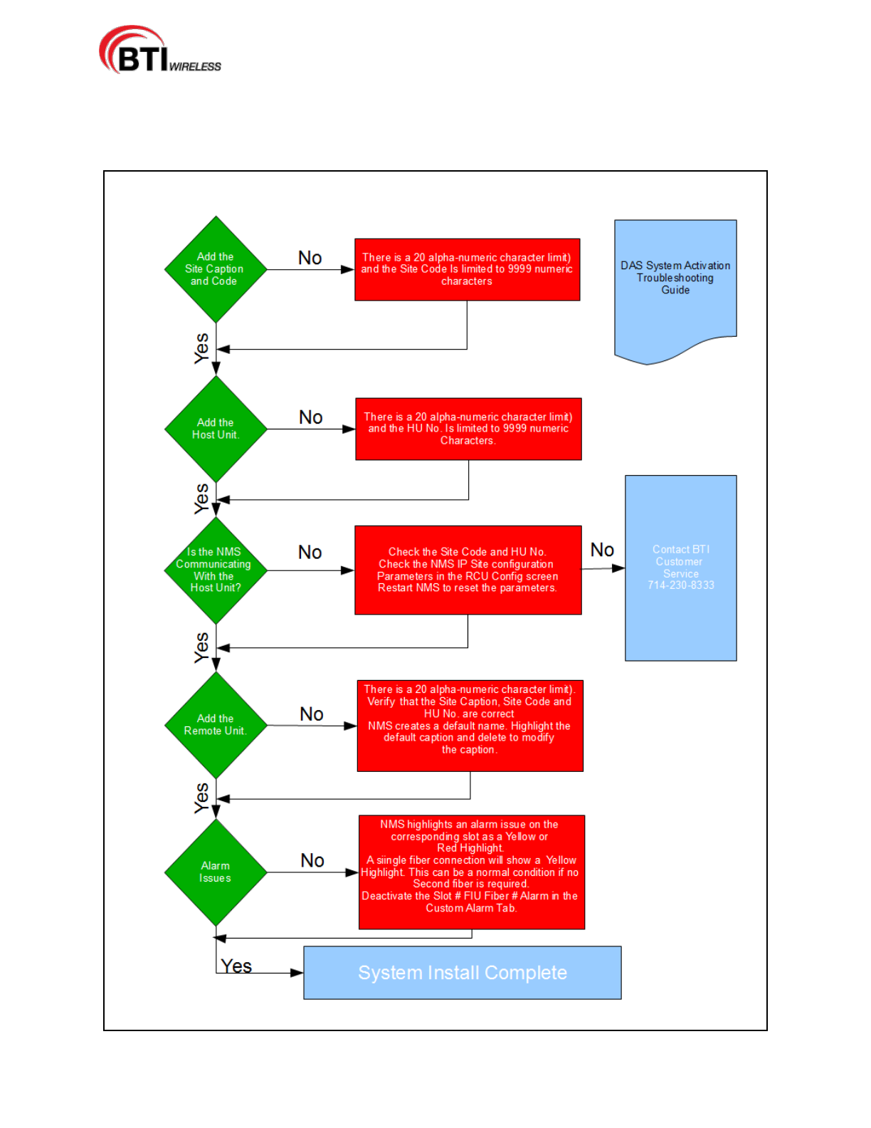
mBSC-H DAS System
Installation Manual Issue 7
© 2009-2014, BTI Wireless Page 92
5.3.4 Troubleshooting
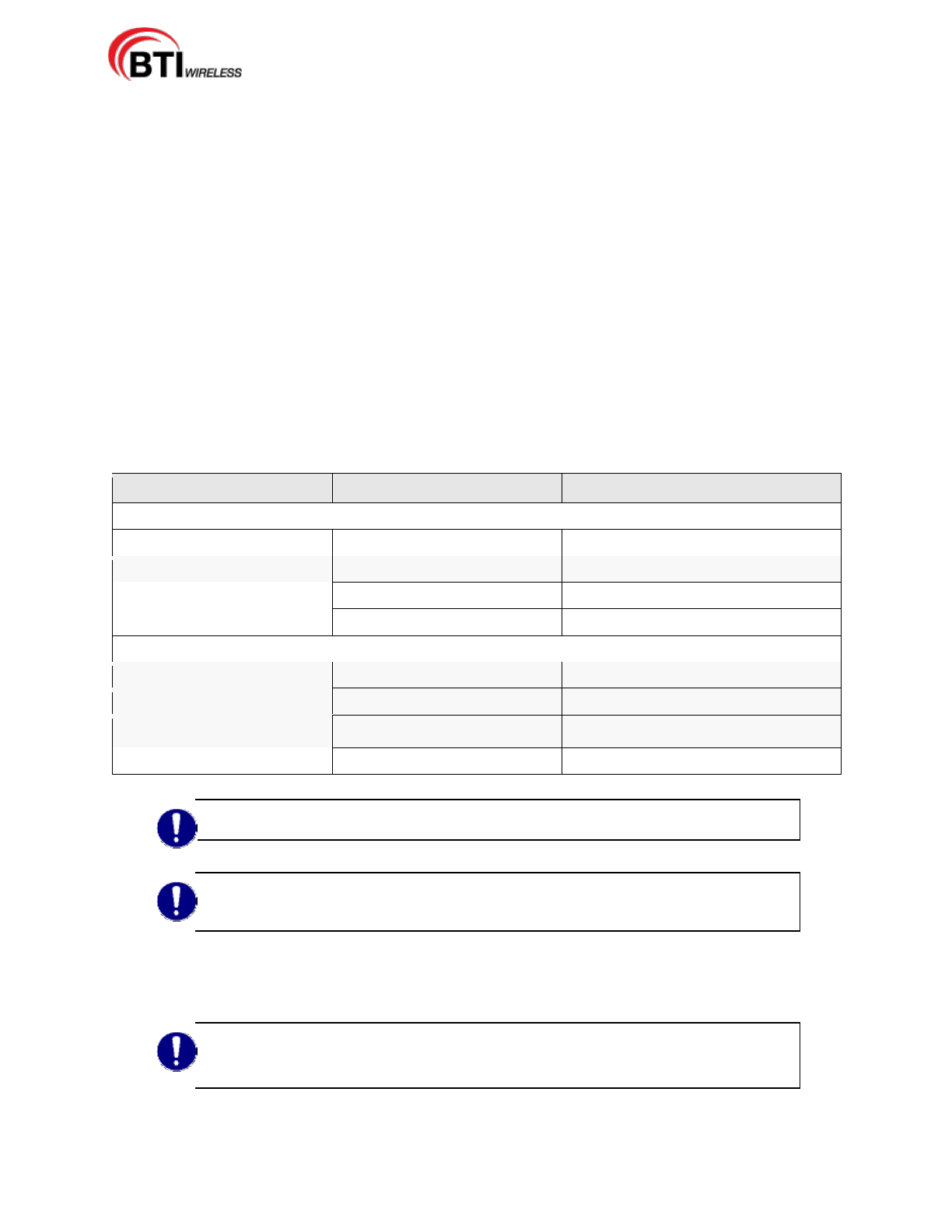
mBSC-H DAS System
Installation Manual Issue 7
© 2009-2014, BTI Wireless Page 93
6 Maintenance
6.1 GENERAL
Please read the general Safety Precautions contained in Section 1.2 Safety Precautions
The mBSC-H Fiber Distributed Antenna System (DAS) system has been designed to require minimal
maintenance with component replacement as the primary method of maintenance. Care must be taken to
prevent unintentional damage to any module seals. Only units which can be replaced without tuning or
soldering are listed in the Replacement Parts List as Warranty may be voided if the module seals are
damaged. It is important to work within the Return Material Authorization (RMA) process when ordering
replacement parts.
Appropriate tools are required for correct handling of replacement maintenance. Please follow any
replacement instructions provided by the manufacturer. Fastening procedures are as follows:
Fastening: Clockwise turns of the tool are required
Unfastening: Counter-clockwise turns of the tool are required
Table 6-1: Replacement Parts List
BTI mBSC-H Component
BTI Replacement Parts
Notes
Host Unit
BIU
FIU
RCU
PSU
Remote Unit
Mounting Bracket
Shroud
Fan Unit
Remote Unit
NOTE: It is important to label any unlabeled cables. prior to disconnecting the cables, to
maintain proper connections once any inspection or maintenance is complete.
NOTE: All internal housing interventions may void Warranty as module seals may
become damaged. Replace any defective parts with original parts from the
manufacturer.
6.2 HOST UNIT
NOTE: It is important to note that preventative maintenance is not required for the Host
Unit.
It is important to note that preventative maintenance is not required for the Host Unit. In the event, a
mBSC-H DAS System
Installation Manual Issue 7
© 2009-2014, BTI Wireless Page 94
component of the Host Unit requires replacement, care must be taken with modules so that seals are not
damaged unintentionally as this may void warranty.
Please see the Replacement Parts List for specific components available.
6.3 NMS
The NMS may require periodic updates, both Firmware and Software. Please see Sections 4.4.7 Firmware
Updates and 4.4.8 Software Upgrade Installation.
6.4 REMOTE UNITS
It is important to note that preventative maintenance is not required for the Remote Unit.
Danger: Disconnect the Remote Unit from the mains prior to any maintenance.
NOTE: It is important to note that preventative maintenance is not required for the
Remote Unit.
6.4.1 Fans
Visually inspect fan units at intervals based upon the location, corresponding environment and pollution
levels. Maintenance is not required for the fan units, but the fan units may be cleaned, if needed using any
commercially available small compressed air device (max. 5 bar).
Once an RU has been powered up for the first time, the fans rotate at full speed. After one minute, the fan
speed will decrease to 75% and after another minute, the fan speed decreases to 25% and will then stay at
25% until the RU reaches its normal operating temperature.
In a normal operating situation, the fans are generally operating at approximately 50% of their power, this
helps prevent dust and other contaminants from settling on the fan blades and the cooling fins. A fan alarm
will be generated should the fan current drop below its normal operating fan speed. Please see the
Replacement Parts list should a replacement fan unit be required and follow any replacement instructions
provided by the manufacturer.

mBSC-H DAS System
Installation Manual Issue 7
© 2009-2014, BTI Wireless Page 95
7 CUSTOMER SERVICE CONTACT
INFORMATION
USA
BTI Wireless
6185 Phyllis Dr. Unit D. Cypress, CA 90630, USA
Tel: +1 714-230-8333
Fax: +1 714-230-8341
E-mail:
Customer Service: CustomerService@bravotechinc.com
Sales: sales@bravotechinc.com
China
BTI (Shenzhen) Co., Ltd.
No.8 Building, Zone #3, Tangtou Industrial Park,
Shiyan, Baoan District, Shenzhen, Guangdong
P.R.China 518102
Tel: +86 755-2951-2233
Fax: +86 755-2951-2299
E-mail: chinasales@bravotechinc.com