BTI Wireless LPA2100 Multi-Carrier Power Amplifier User Manual
Bravo Tech (Shenzhen) Co. Ltd. Multi-Carrier Power Amplifier Users Manual
Users Manual
LPA2100-160-SW01
BRAVO TECH INC
Add.: 6185 Phyllis Drive Unit D, Cypress, CA 90630
Phone: 1-714-230-8333 Website: www.bravotechinc.com
Revision: SP·LPA2100-160-SW01·REV.A
Page: 1
LPA2100-160-SW01 SPECIFICATION
1. System advantages
Bravo Tech Inc 's newly introduced Multi-Carrier High Power Outdoor Booster platform provides high
er downlink EIRP and improved uplink sensitivity at the same time to extend the coverage of existing cellu
lar networks. This multi-carrier based product platform can also work with customized BTS to extend capa
city of original BTS with a low system total cost. This product platform features:
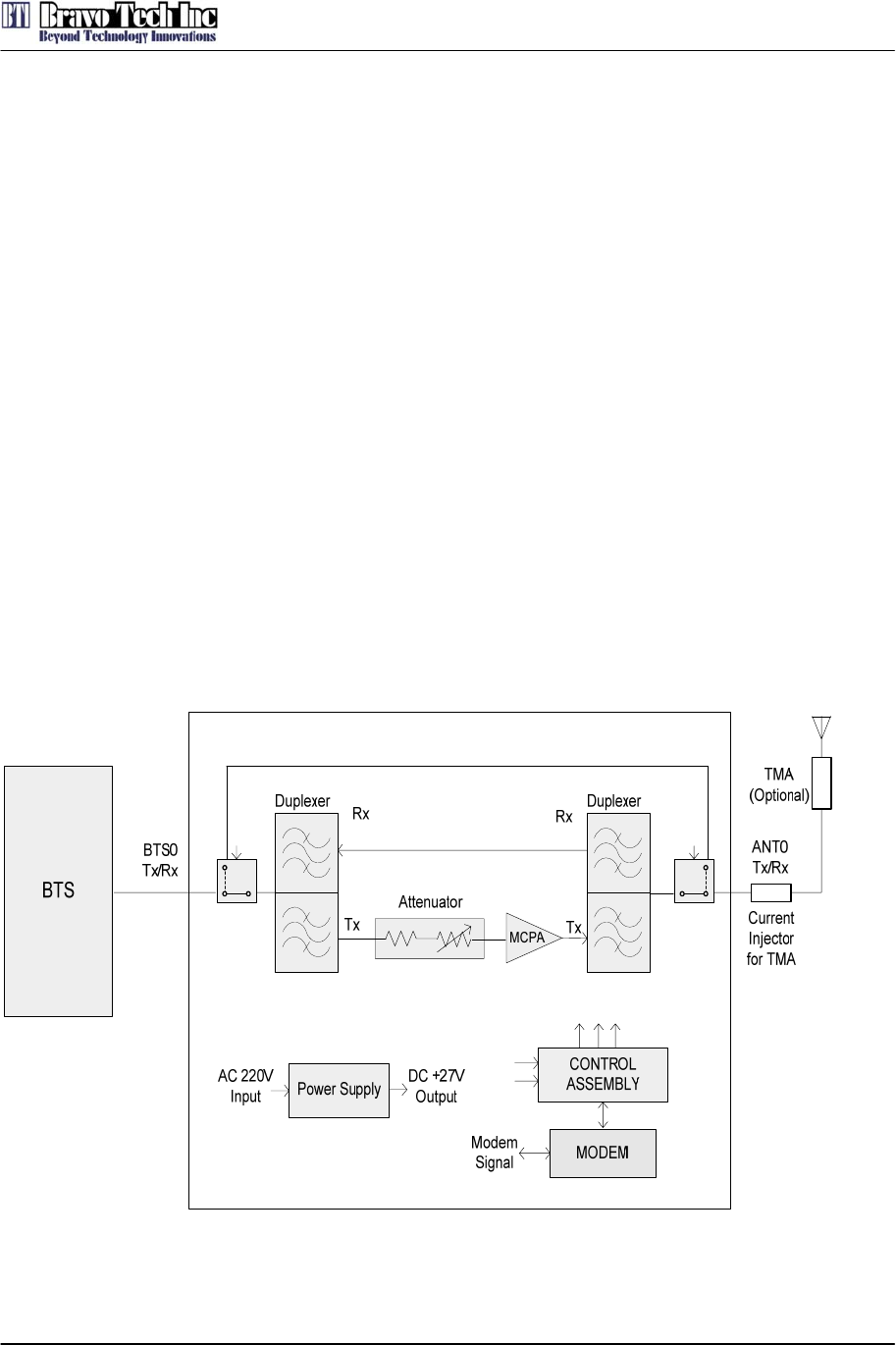
• Support multi-carrier CDMA signals, with mixed mode operation
• Output maximum power 160W, support carriers number up to 4.
• Very High System Efficiency
• Extensive product monitoring and control (local and remote)
• Centralized system control/display/alarms
• Great system reliability supported by architecture built-in redundancy
• Powered by 30VDCavailable
• Extensive protection for lightning, voltage surge, and any high failure rate assemblies
• Compact system size and light weight
2. System Block Diagram

LPA2100-160-SW01
BRAVO TECH INC
Add.: 6185 Phyllis Drive Unit D, Cypress, CA 90630
Phone: 1-714-230-8333 Website: www.bravotechinc.com
Revision: SP·LPA2100-160-SW01·REV.A
Page: 2
3. Electrical Specifications
PARAMETER SPECIFICATION
Frequency 2110 ~ 2155 MHz
Output Power 160Watts average max. ( CDMA2000, PAR:8.0dB)
Spurious Emission
-45dBc@∆f=885-1.25MHz, 30kHz RBW
-55dBc@∆f=1.25-1.98MHz, 30kHz RBW
-55dBc@∆f=1.25-2.25MHz, 30kHz RBW
-13dBm@∆f=2.25-4MHz, 30kHz RBW
RF Gain 57.0 ± 1.0dB @ frequency range, +30Vdc, room temp.
Normal Operating Voltage +30Vdc±1.0Vdc
Operating Voltage +29Vdc ~ +31Vdc
RF Gain Variation over
Voltage & Temperature ±1.5dB @ +29≤Vsup≤+31V, -20℃ to +50℃
Gain Flatness Peak to Peak 0.2dB over any 5MHz
Input/Output Return Loss -16dB min.
Output Protection Mismatch protected with isolator
Efficiency ≥12%@+30Volts, Po=+52dBm
Operating Temperature -20℃ to +50℃ (Air Temperature inside System),
Operating point Output power:52.5dBm ± 0.5dB
Operating range 6dB min
Input Power ALC
Over Pwr Output Pwr:53dBm ± 0.5dB
4. Alarm and Functions Specifications
TTL output for the alarm pins. Normal is High, Alarm is Low.
4.1 Over temperature alarm
Alarm and shutdown at 85 base temperature, auto℃-recover at 65 base temperature.℃
4.2 Over power alarm
Alarm and shutdown when output power is over 52.5dBm, no auto-recover.
4.3 ALC
4.3.1 ALC level: 52.5±0.5dBm
4.3.2 ALC range: ≥6dB
4.4 Over driver alarm
Alarm and shutdown when input power is over+1dBm, no auto-recover.
4.5 Transistor fail alarm
Alarm and shutdown when gain reduce 10dB, no auto-recover
4.6 VSWR alarm
Alarm and shutdown when reject is over 43dBm, no auto-recover.
LPA2100-160-SW01
BRAVO TECH INC
Add.: 6185 Phyllis Drive Unit D, Cypress, CA 90630
Phone: 1-714-230-8333 Website: www.bravotechinc.com
Revision: SP·LPA2100-160-SW01·REV.A
Page: 3
5. Description of the connectors
5.1 RF Part
Port Name Type Warning
Input SMA Female (50Ω) Normal :-5.2dBm
maxium input power +1dBm.
Output N Female (50Ω) Normal :51.76dBm
maxium output power 52.5dBm.
5.2 DC power
Port Name Type NO Warning
A1、A2 VDC type +30V, range 24~32V
DC IN
D-Sub type
DSCD175PS1M
(Male) A3、A4 GND to VDC
5.3 Communication
Connector type: USB
Note: Manufacter use to debug.
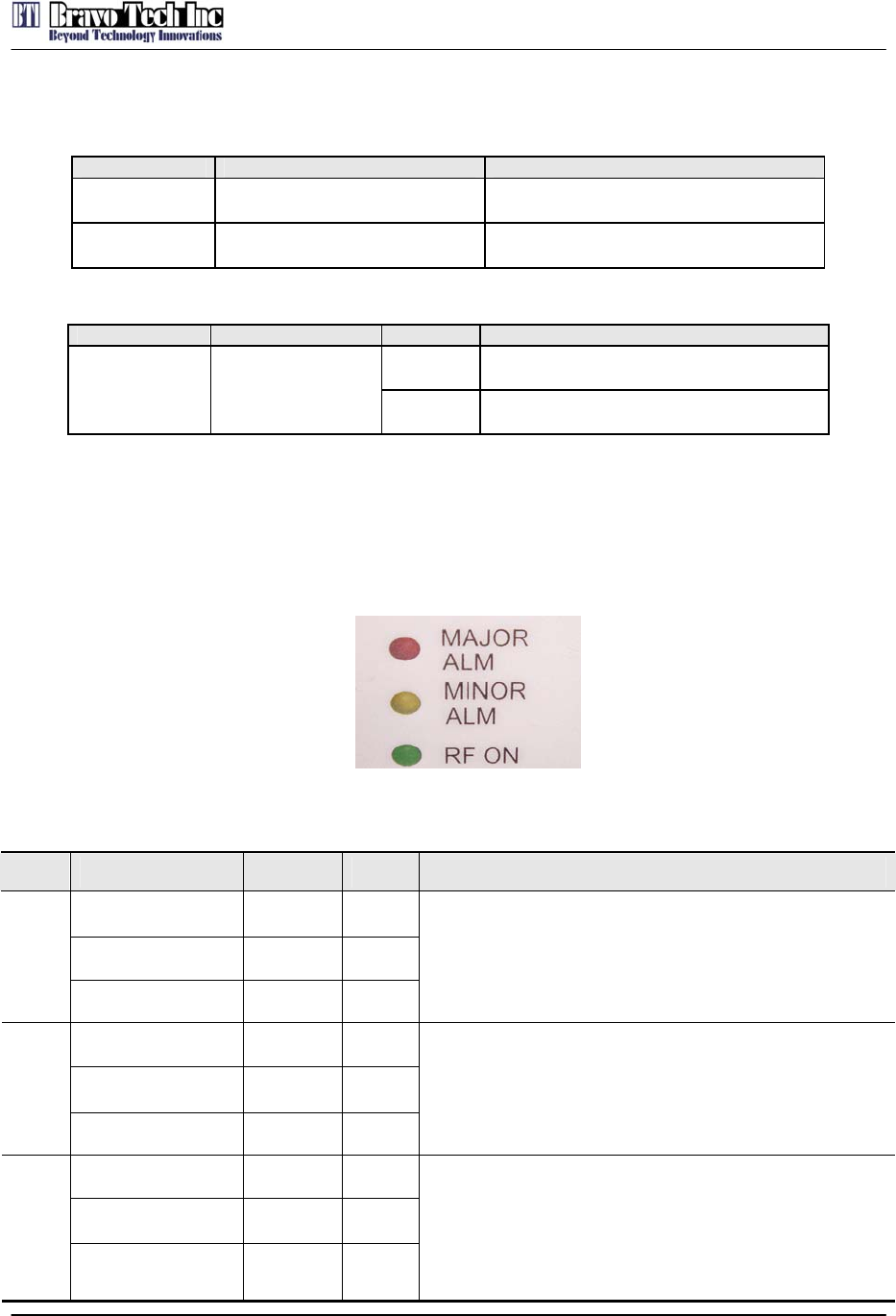
5.4 LED Indication
Figure 1 Power Amplifier Indicators
Table 1 Specification of Power Amplifier Indicator Light
Item Label Color State Specification
MAJOR ALM Red On
MINOR ALM Yellow Off
1
RF ON Green Off
Power amplifier alarms and shuts down
MAJOR ALM Red Off
MINOR ALM Yellow On
2
RF ON Green Off
Power amplifier alarms but still works
MAJOR ALM Red Off
MINOR ALM Yellow Off
3
RF ON Green On
Power amplifier works normally

LPA2100-160-SW01
BRAVO TECH INC
Add.: 6185 Phyllis Drive Unit D, Cypress, CA 90630
Phone: 1-714-230-8333 Website: www.bravotechinc.com
Revision: SP·LPA2100-160-SW01·REV.A
Page: 4
5.5 Warning
1. Check the power supply voltage is between 24V and 32V or not before electrify, better
to setup in 30V. Power of power supply shall bigger than 1400W.
2. Ensure the power supply polarity is right, port A1、A2 are anode, and port A3、A4 are
cathode.
3. Ensure the output line is connected and input power is not over load before connect
the RF input line.
4. Use the type N connector as output connector, for the high output power, suggest to
using the φ3 upwards RF cable to connect. At the same time, output matching deman
d all right, SWR more than 1.5 is better, but less than 3.0.
5. Product operating should be cooled by air flow, air flow more than 150cfm.
6. Product operating room temperature can’t above 50o ,also can’t below -20o。
LPA2100-160-SW01
BRAVO TECH INC
Add.: 6185 Phyllis Drive Unit D, Cypress, CA 90630
Phone: 1-714-230-8333 Website: www.bravotechinc.com
Revision: SP·LPA2100-160-SW01·REV.A
Page: 5
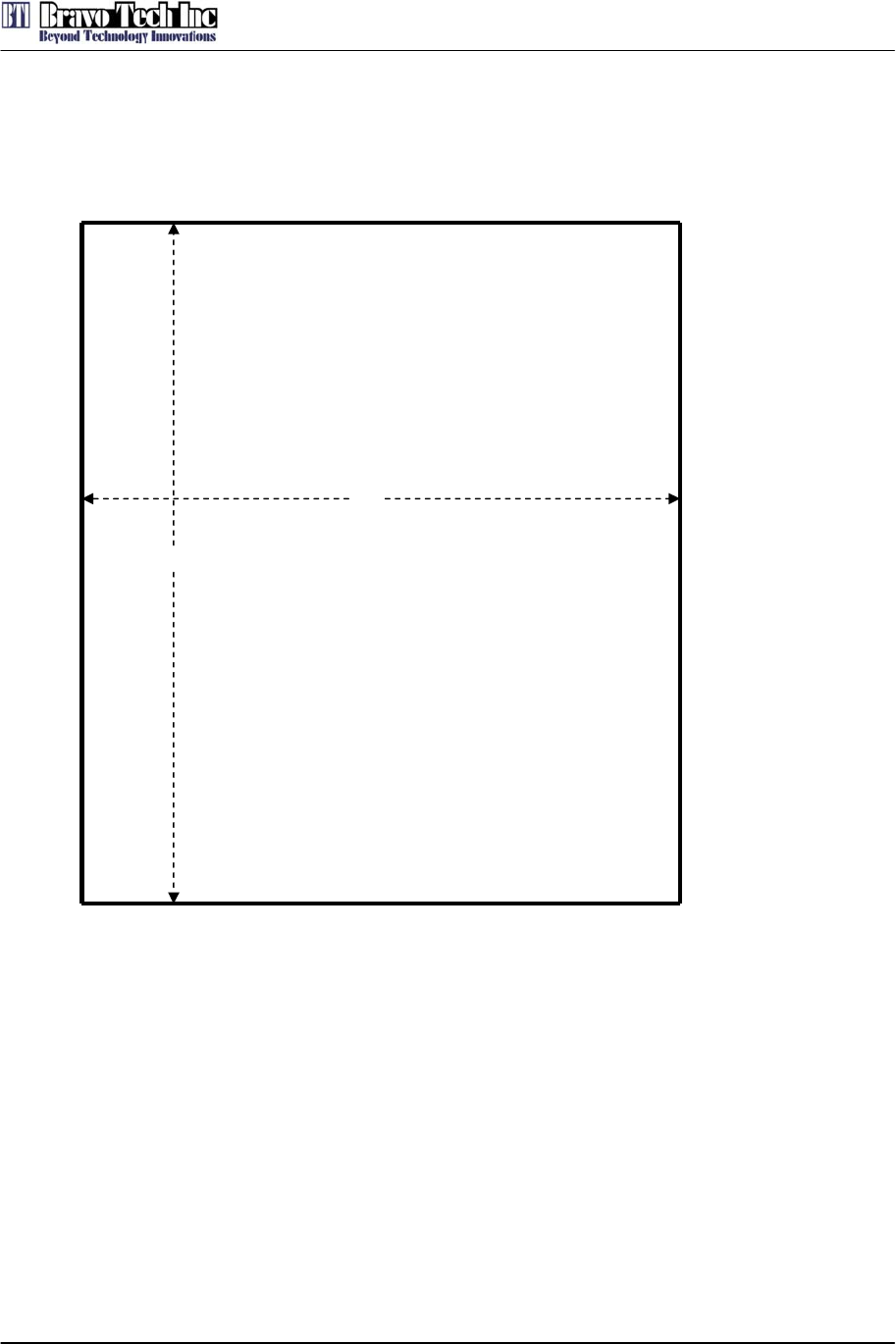
6. Dimension
Figure 2 Dimension
345
450
Left Right
Front
Rear
Unit: mm
LPA2100-160-SW01
BRAVO TECH INC
Add.: 6185 Phyllis Drive Unit D, Cypress, CA 90630
Phone: 1-714-230-8333 Website: www.bravotechinc.com
Revision: SP·LPA2100-160-SW01·REV.A
Page: 6
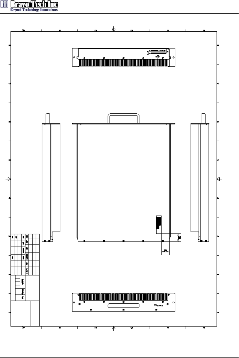
Figure 3 Mechanical drawing
LPA2100-160-SW01
BRAVO TECH INC
Add.: 6185 Phyllis Drive Unit D, Cypress, CA 90630
Phone: 1-714-230-8333 Website: www.bravotechinc.com
Revision: SP·LPA2100-160-SW01·REV.A
Page: 7
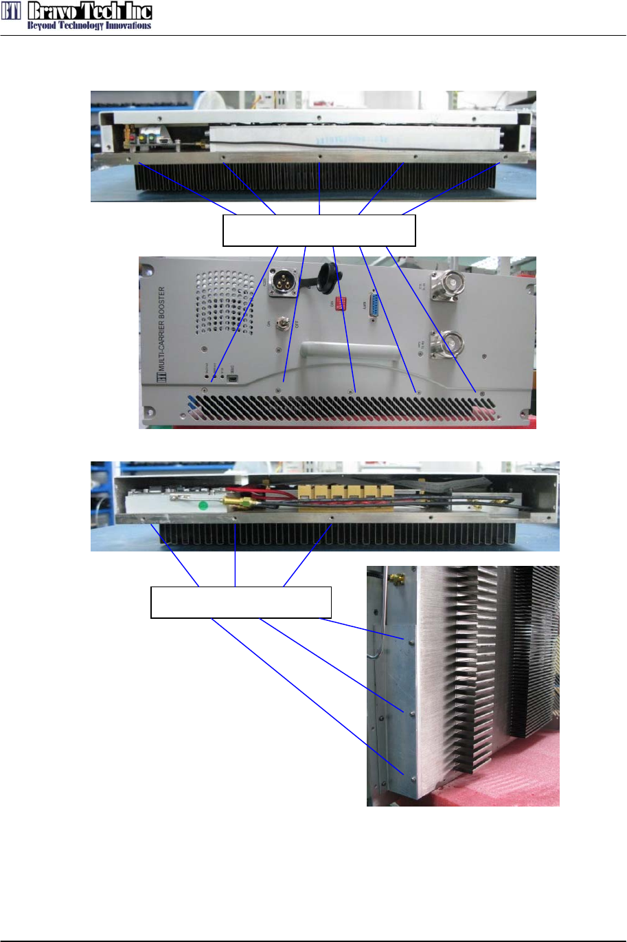
7. Assembled
Figure 4 Assembled Instructions
1. Lock 5 screws 4-40, L3/8 inch with Philip's type screwdriver to fasten the front side of PA to
the Front Plate of Booster as shown above.
2. Lock 3 screws 4-40, L5/8 inch with Philip's type screwdriver to fasten the back side of PA to a
connection board which is connected to the soleplate of Booster.
5 screws 4-40, L3/8 inch
3 screws 4-40, L5/8 inch