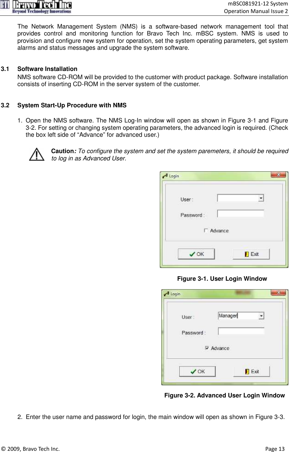
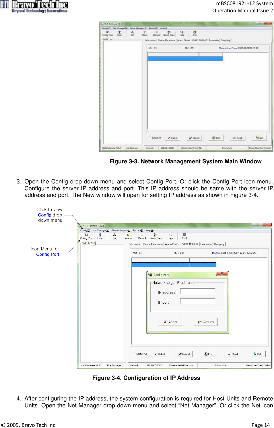
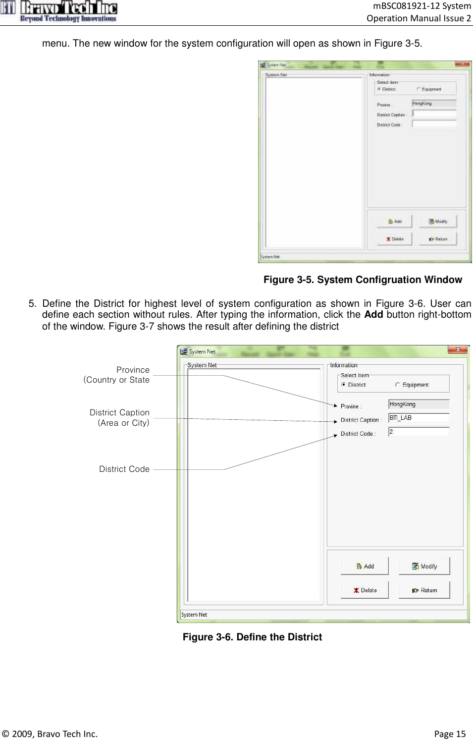
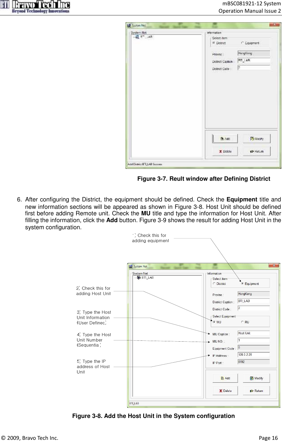
BTI Wireless MBSC081921-21 Multi-Band, Multi-Standard, Multi-Carrier Coverage System (WCDMA 2100) User Manual mBSC081921 12 Operation Manual Issue2
Bravo Tech (Shenzhen) Co. Ltd. Multi-Band, Multi-Standard, Multi-Carrier Coverage System (WCDMA 2100) mBSC081921 12 Operation Manual Issue2
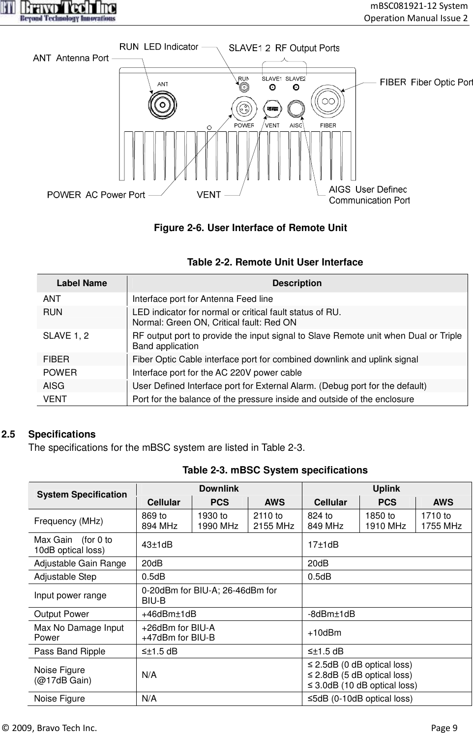
Users Manual
![mBSC081921-12 ISSUE 2 mBSC081921-12 Multi-Band, Multi-Standard, Multi-Carrier Coverage System Operation Manual](https://usermanual.wiki/BTI-Wireless/MBSC081921-21/User-Guide-1283351-Page-1.png)
![mBSC081921-12 System Operation Manual Issue 2 © 2009, Bravo Tech Inc. Page 2 COPYRIGHT This document is the Operation Manual for Bravo Tech Inc. mBSC system. Bravo Tech Inc. reserves the right to change the contents without prior notice. No part of this document may be reproduced or utilized. © 2009, Bravo Tech Inc, All Rights Reserved REVISION HISTORY Issue No. Description Date 1 Initial Draft Dec. 15, 2009 2 Update the specification Jan. 18, 2010 TABLE OF CONTENTS Content Page 1 Introduction...................................................................................................................... 4 2 Thoery of operation.......................................................................................................... 4 2.1 System Overview ..................................................................................................... 4 2.2 Basic System Components....................................................................................... 4 2.3 Host Unit Description................................................................................................ 4 2.3.1 Basic Functions of HU ................................................................................. 5 2.3.2 HU Interface Ports Description..................................................................... 5 2.4 Remote Unit Description........................................................................................... 6 2.4.1 Basic Functions of RU ................................................................................. 8 2.4.2 RU Interface Ports Description..................................................................... 8 2.5 Specifications........................................................................................................... 9 3 Network Management system ........................................................................................ 12 3.1 Software Installation............................................................................................... 13 3.2 System Start-Up Procedure with NMS .................................................................... 13 3.3 Read and Edit the current system setting parameters............................................. 19 3.4 Read and Modify the System Gain Budget ............................................................. 20 3.5 Check Alarm Status for the system ......................................................................... 21 3.6 Check the Major performance for the system.......................................................... 22 4 antenna Mount environment........................................................................................... 23 5 fcc warning..................................................................................................................... 23 6 customer Contact information......................................................................................... 23 Figure 2-1. System Overview Structure.................................................................................... 4 Figure 2-2. Host Unit ............................................................................................................... 5 Figure 2-3. User Interface of Host Unit..................................................................................... 6 Figure 2-4. 3 Remote Unit Assembly Without Solar Shell ......................................................... 7 Figure 2-5. 3 Remote Unit Assembly With Solar Shell .............................................................. 8 Figure 2-6. User Interface of Remote Unit................................................................................ 9 Figure 3-1. User Login Window.............................................................................................. 13 Figure 3-2. Advanced User Login Window ............................................................................. 13](https://usermanual.wiki/BTI-Wireless/MBSC081921-21/User-Guide-1283351-Page-2.png)
![mBSC081921-12 System Operation Manual Issue 2 © 2009, Bravo Tech Inc. Page 3 Content Page Figure 3-3. Network Management System Main Window ....................................................... 14 Figure 3-4. Configuration of IP Address ................................................................................. 14 Figure 3-5. System Configruation Window ............................................................................. 15 Figure 3-6. Define the District ................................................................................................ 15 Figure 3-7. Reult window after Defining District...................................................................... 16 Figure 3-8. Add the Host Unit in the System configuration...................................................... 16 Figure 3-9. Result Window after adding HU ........................................................................... 17 Figure 3-10. Add the Remote Unit below the Host Unit Tree................................................... 17 Figure 3-11. Completion of the System Configuration............................................................. 18 Figure 3-12. Read the current setting for teh system .............................................................. 19 Figure 3-13. Modify the parameters for the system................................................................. 19 Figure 3-14. Modify the parameters for the system................................................................. 20 Figure 3-15. Read the current Alarm Status............................................................................ 21 Figure 3-16. Change the Alarm Setting .................................................................................. 21 Figure 3-17. Check the system performance.......................................................................... 22 Table 2-1. Remote Unit User Interface ..................................................................................... 6 Table 2-2. Remote Unit User Interface ..................................................................................... 9 Table 2-3. mBSC System specifications................................................................................... 9 Table 3-1. Rule for numbering the Equipment Code ............................................................... 18 SAFETY CAUTIONS Danger: Danger is used to indicate the presence of a harzard that will cause server personal injury or substantial property damage if the harzard is not abvoided. Warning: Warning is used to indicate the presence of a harzard that can cause server personal injury or substantial property damage if the harzard is not abvoided. Caution: Caution is used to indicate the presence of a harzard that will or can cause minor personal injury or substantial property damage if the harzard is not abvoided. Glossary and Acronyms The acronyms and abbreviations used in this manual are detailed in the following list. mBSC Multi-Band, Multi-System, Multi-Carrier HU Host Unit RU Remote Unit FIU Fiber optic Interface Unit BIU Base station Interface Unit RCU Remote Control Unit PSU Power Supply Unit NMS Network Management System](https://usermanual.wiki/BTI-Wireless/MBSC081921-21/User-Guide-1283351-Page-3.png)
![mBSC081921-12 System Operation Manual Issue 2 © 2009, Bravo Tech Inc. Page 4 1 INTRODUCTION This document provides the basic description, application and configuration for Bravo Tech Inc. mBSC081921-12 system. Throughout this publication, 2 THOERY OF OPERATION 2.1 System Overview mBSC081921-12 is the economic and convenient coverage solution of DAS system which has a fiber transport. The system consists of HU (Host unit) and RU (Remote unit). The HU is mounted in a 19” rack and are intend for use indoor environment. The RU can work in outdoor environment. The output power of the RU is 40W. The transport between HU and RU is fiber optic. The downlink and uplink optical signal are duplex so there is only one fiber needed. 2.2 Basic System Components The basic components of Bravo Tech Inc. mBSC system and their functions are shown in Figure 2-1. A basic mBSC system consists of a Host Unit (HU) and a Remote Unit (RI). The Host unit has multiple slot assembly that mounts in a standard equipment rack. The RU consists of multiple electronic and optical modules for supporting multiple Standards, which mounts in outdoor wall or pole. Control and monitoring functions are provided by the Network Management System (NMS). Remote Unit(RU)Cellular PCS AWSRemote Unit(RU)Cellular PCS AWSRemote Unit(RU)Cellular PCS AWSRemote Unit(RU)Cellular PCS AWSHost UnitOptical FiberOptical Fiber Optical FiberOptical FiberOperator NMS ServerEthernet Figure 2-1. System Overview Structure 2.3 Host Unit Description The HU, shown in Figure 2-3, consists of RF conditioning units (BIU) and optical TRX modules (FIU). HU combines the 3 band downlink RF signals from BTS and converters them to optical signal. At the same time, HU converts the uplink optical signals to RF signals and splits and filters out 3 band RF signals.](https://usermanual.wiki/BTI-Wireless/MBSC081921-21/User-Guide-1283351-Page-4.png)
![mBSC081921-12 System Operation Manual Issue 2 © 2009, Bravo Tech Inc. Page 5 Figure 2-2. Host Unit 2.3.1 Basic Functions of HU HU provides the following basic functions. • BIU (Base station Interface Unit): RF interface module with Base Station • FIU (Fiber optic Interface Unit): Optical TRX module. Convert RF signals to Optic signals • RCU (Remote Control Unit): Ethernet Interface module for Network Management Software • PSU (Power Supply Unit): Power Supply unit for providing DC power to BIU, FIU and RCU module 2.3.2 HU Interface Ports Description Each interface port, shown in Figure 3, is described in below Table 1.](https://usermanual.wiki/BTI-Wireless/MBSC081921-21/User-Guide-1283351-Page-5.png)
![mBSC081921-12 System Operation Manual Issue 2 © 2009, Bravo Tech Inc. Page 6 Figure 2-3. User Interface of Host Unit Table 2-1. Host Unit User Interface Board Name Port Name Description Remark TX1, TX2 Downlink interface ports to be connected to BIU RF signal RX1, RX2 Uplink interface ports to be connected to BIU RF signal FC/APC1, FC/APC2 Fiber optic interface ports to be connected to RU Optical signal E911-800-1, E911-800-2 The cellular band coupling uplink signal for LMU RF signal E911-1900-1, E911-1900-1 The PCS band coupling uplink signal for LMU RF signal FIU E911-2100-1, E911-2100-1 The AWS band coupling uplink signal for LMU RF signal TX1, TX2, TX3, TX4 The combined downlink signal to FIUs RF signal RX1, RX2, RX3, RX4 The combined uplink signal from FIUs RF signal AWS-1, AWS-2 The interface to AWS band BTS TX/RX ports RF signal PSC-1, PCS-2 The interface to PCS band BTS TX/RX ports RF signal BIU Cellular -1, Cellular-2 The interface to cellular band BTS TX/RX ports RF signal 2.4 Remote Unit Description The Remote Unit, shown in Figure 2-5 and Figure 2-6, consists of optical module (O/E), downlink power amplifier, LNA and duplexer. Optical module converts the downlink optical signal from the HU and splits the RF signal to 3 RU. It also converts the uplink RF signal to optical signal and sends it to](https://usermanual.wiki/BTI-Wireless/MBSC081921-21/User-Guide-1283351-Page-6.png)
![mBSC081921-12 System Operation Manual Issue 2 © 2009, Bravo Tech Inc. Page 7 the HU. Each optical module can support 3 RU in different band. The 3 RU were assembled together as a whole. Figure 2-4. 3 Remote Unit Assembly Without Solar Shell](https://usermanual.wiki/BTI-Wireless/MBSC081921-21/User-Guide-1283351-Page-7.png)
![mBSC081921-12 System Operation Manual Issue 2 © 2009, Bravo Tech Inc. Page 8 Figure 2-5. 3 Remote Unit Assembly With Solar Shell 2.4.1 Basic Functions of RU The RU provides the following functions: • Convert downlink optic signal to RF signal and uplink RF signal to optic signal • Booster the forward RF signal from HU to high power level (Max output: 40W / RU) • Amplify the uplink signal from antenna to improve the system receive sensitivity 2.4.2 RU Interface Ports Description Each interface port of Remote Unit, shown in Figure 2-7, is described in below Table 2-2.](https://usermanual.wiki/BTI-Wireless/MBSC081921-21/User-Guide-1283351-Page-8.png)
![mBSC081921-12 System Operation Manual Issue 2 © 2009, Bravo Tech Inc. Page 9 Figure 2-6. User Interface of Remote Unit Table 2-2. Remote Unit User Interface Label Name Description ANT Interface port for Antenna Feed line RUN LED indicator for normal or critical fault status of RU. Normal: Green ON, Critical fault: Red ON SLAVE 1, 2 RF output port to provide the input signal to Slave Remote unit when Dual or Triple Band application FIBER Fiber Optic Cable interface port for combined downlink and uplink signal POWER Interface port for the AC 220V power cable AISG User Defined Interface port for External Alarm. (Debug port for the default) VENT Port for the balance of the pressure inside and outside of the enclosure 2.5 Specifications The specifications for the mBSC system are listed in Table 2-3. Table 2-3. mBSC System specifications Downlink Uplink System Specification Cellular PCS AWS Cellular PCS AWS Frequency (MHz) 869 to 894 MHz 1930 to 1990 MHz 2110 to 2155 MHz 824 to 849 MHz 1850 to 1910 MHz 1710 to 1755 MHz Max Gain (for 0 to 10dB optical loss) 43±1dB 17±1dB Adjustable Gain Range 20dB 20dB Adjustable Step 0.5dB 0.5dB Input power range 0-20dBm for BIU-A; 26-46dBm for BIU-B Output Power +46dBm±1dB -8dBm±1dB Max No Damage Input Power +26dBm for BIU-A +47dBm for BIU-B +10dBm Pass Band Ripple ≤±1.5 dB ≤±1.5 dB Noise Figure (@17dB Gain) N/A ≤ 2.5dB (0 dB optical loss) ≤ 2.8dB (5 dB optical loss) ≤ 3.0dB (10 dB optical loss) Noise Figure N/A ≤5dB (0-10dB optical loss)](https://usermanual.wiki/BTI-Wireless/MBSC081921-21/User-Guide-1283351-Page-9.png)
![mBSC081921-12 System Operation Manual Issue 2 © 2009, Bravo Tech Inc. Page 10 Downlink Uplink System Specification Cellular PCS AWS Cellular PCS AWS (@6dB Gain) Dynamic range N/A 60dB System delay ≤ 500ns Optic Link Budget 10dB (full performance) , 15dB (derate) Optic Wavelength 1310/1550nm ALC range 6dB 30dB VSWR ≤1.5 Antenna Port 7/16 DIN female Optical connector FC/APC (HU) ; LC/PC (RU) Power Supply DC -48V (HU) ; AC 110/220V (RU) Waterproof IP40 (HU) ; IP65 (RU) NMS Support SNMPv2 Downlink Uplink BIU Specification Cellular PCS AWS Cellular PCS AWS Frequency (MHz) 869 to 894 MHz 1930 to 1990 MHz 2110 to 2155 MHz 824 to 849 MHz 1850 to 1910 MHz 1710 to 1755 MHz Max No of Plug-in module 6 for low power (BIU-A) 3 for High power (BIU-B) Input power level 0 ~ 20dBm for low power module, 26-46dBm for high power module Input/Output VSWR ≤ 1.5 Temperature of operation -40˚C ~ +60˚C Power supply DC -48V Current < 1A @ Full power output Weight 17Kg Dimensions (H x W x D) 177mm x 485mm x 445mm MTBF 100 , 000 Hours No of BTS interface/per band 2 Max No of divided output 4/per module RF Port SMA NMS Interface Ethernet Optical module (FIU) specification Specification Notes Optical Wavelength 1310 ± 20nm (HU) 1550 ± 20nm (RU) Optical Output Power 4dBm ± 2dB Optical Input Power -18 ~ 6dBm Tx Alarm optical output power < -3dBm Software setting Rx Alarm Optical input power < -15dBm Software setting WDM Embedded Fiber Connector FC/APC Frequency 700 ~ 2200MHz Link Gain 0 ± 2dB (Uplink , Downlink) @ 0 ~ 10dB fiber loss Default Flatness ≤ 1dB in each band VSWR ≤ 1.4](https://usermanual.wiki/BTI-Wireless/MBSC081921-21/User-Guide-1283351-Page-10.png)
![mBSC081921-12 System Operation Manual Issue 2 © 2009, Bravo Tech Inc. Page 11 Optical module (FIU) specification Specification Notes Third-order Intermodulation ≤ -65dBc (0dBm/2 tone) Noise ≤ -134dBm/Hz (RF Gain: 0dB) RF Isolation ≥ 60dB Spurious ≤ -60dBm / 100KHz (100MHz ~ 3GHz) Delay 60ns Temperature of operation -20 ~ +65˚C Current ≤ 200mA/per module (+12V Power Supply) Power Supply DC +5.6V ~ +15V , Power Consumption: < 2.5W Communication Interface RS232 and RS485 Interface Data Rate: Software Setting NMS Specification Specification Notes Max No of port 30 (manage 30 BIU rack or FIU rack , 1080 Remote unit) SNMP based management yes Web browser yes Real time alarm display yes Display various system level values yes Voltages , RF power etc. Remote download yes Cellular Band Remote Unit Specification Downlink Uplink Frequency 869 to 894 MHz 824 to 849 MHz Output Power +46dBm±1dB -8dBm±1dB |∆f| ≥750kHz ≥ 45dBc / 30kHz ACPR |∆f| ≥1.98MHz ≥ 60dBc / 30kHz 90kHz < f < 150kHz ≤ -13dBm / 1kHz 150kHz < f < 30MHz ≤ -13dBm / 10kHz 30MHz< f < 1GHz ≤ -13dBm / 100kHz Spurious Emission 1GHz < f < 5GHz ≤ -13dBm / 1MHz N/A Noise figure N/A ≤ 2.5dB ALC range 6dB 30dB VSWR ≤1.5:1 ANT port 7/16 female Optical interface (master RU only) LC/PC Temperature of operation -40 ~ +60˚C Power supply AC 110V / 220V ± 20% Current < 1A @ Full power, 110VAC / 220VAC input Weight 16Kg Dimensions (H x W x D) 120mm x 250mm x 500mm Weatherproof IP65 MTBF 100,000 Hours NMS Interface Ethernet PCS Band Remote Unit Specification Downlink Uplink Frequency (MHz) 1930 to 1990 1850 to 1910](https://usermanual.wiki/BTI-Wireless/MBSC081921-21/User-Guide-1283351-Page-11.png)
![mBSC081921-12 System Operation Manual Issue 2 © 2009, Bravo Tech Inc. Page 12 PCS Band Remote Unit Specification Downlink Uplink Output Power +46dBm±1dB -8dBm±1dB |∆f| ≥885kHz ≥ 45dBc / 30kHz |∆f| ≥1.25 to 2.25MHz ≤-9dBm / 30kHz ACPR |∆f| ≥2.25 to 4MHz ≤-13dBm / 1MHzHz 9kHz < f < 150kHz ≤ -13dBm / 1kHz 150kHz < f < 30MHz ≤ -13dBm / 10kHz 30MHz < f < 1GHz ≤ -13dBm / 100kHz Spurious Emission 1GHz < ∆f < 5GHz ≤ -13dBm / 1MHzkHz N/A Noise figure N/A ≤ 2.5dB ALC 6dB 30dB VSWR ≤ 1.5:1 ANT port 7/16 female Optical interface (master RU only) LC/PC Temperature of operation -40 ~ +60 ˚C Power supply AC 110V / 220V ± 20% Current <1A @ Full power Weight 16Kg Dimensions (H x W x D) 120mm x 250mm x 500mm Weatherproof IP65 MTBF 100,000 Hours NMS Interface Ethernet AWS Band Remote Unit Specification Downlink Uplink Frequency (MHz) 2110 to 2155 1710 to 1755 Output Power +46dBm±1dB -8dBm±1dB |∆f| ≥5MHz ≥ 45dBc / 30kHz ACLR |∆f| ≥10MHz ≥ 50dBc / 30kHz 9kHz < f < 150kHz ≤ -13dBm / 1kHz 150kHz < f < 30MHHz ≤ -13dBm / 10kHz 30MHz < f < 1 GHz ≤ -13dBm / 100kHz 1GHz < f < 5GHz ≤ -13dBm / 1MHz Spurious Emission 5GHz < f < 12.75GHz ≤ -30dBm / 1MHz N/A Noise figure N/A ≤ 2.5dB ALC range 6dB 30dB VSWR ≤ 1.5:1 ANT port 7/16 female Optical interface (master RU only) LC/PC Temperature of operation -40 ~ +60 ˚C Power supply AC 110V / 220V ±20% Current < 1A @ Full power, 110V AC / 220VAC input Weight 16Kg Dimensions (H x W x D) 120mm x 250mm x 500mm Weather proof IP65 MTBF 100,000 Hours NMS Interface Ethernet 3 NETWORK MANAGEMENT SYSTEM](https://usermanual.wiki/BTI-Wireless/MBSC081921-21/User-Guide-1283351-Page-12.png)
![mBSC081921-12 System Operation Manual Issue 2 © 2009, Bravo Tech Inc. Page 13 The Network Management System (NMS) is a software-based network management tool that provides control and monitoring function for Bravo Tech Inc. mBSC system. NMS is used to provision and configure new system for operation, set the system operating parameters, get system alarms and status messages and upgrade the system software. 3.1 Software Installation NMS software CD-ROM will be provided to the customer with product package. Software installation consists of inserting CD-ROM in the server system of the customer. 3.2 System Start-Up Procedure with NMS 1. Open the NMS software. The NMS Log-In window will open as shown in Figure 3-1 and Figure 3-2. For setting or changing system operating parameters, the advanced login is required. (Check the box left side of “Advance” for advanced user.) Caution: To configure the system and set the system paremeters, it should be required to log in as Advanced User. Figure 3-1. User Login Window Figure 3-2. Advanced User Login Window 2. Enter the user name and password for login, the main window will open as shown in Figure 3-3.](https://usermanual.wiki/BTI-Wireless/MBSC081921-21/User-Guide-1283351-Page-13.png)
![mBSC081921-12 System Operation Manual Issue 2 © 2009, Bravo Tech Inc. Page 14 Figure 3-3. Network Management System Main Window 3. Open the Config drop down menu and select Config Port. Or click the Config Port icon menu. Configure the server IP address and port. This IP address should be same with the server IP address and port. The New window will open for setting IP address as shown in Figure 3-4. Figure 3-4. Configuration of IP Address 4. After configuring the IP address, the system configuration is required for Host Units and Remote Units. Open the Net Manager drop down menu and select “Net Manager”. Or click the Net icon](https://usermanual.wiki/BTI-Wireless/MBSC081921-21/User-Guide-1283351-Page-14.png)
![mBSC081921-12 System Operation Manual Issue 2 © 2009, Bravo Tech Inc. Page 15 menu. The new window for the system configuration will open as shown in Figure 3-5. Figure 3-5. System Configruation Window 5. Define the District for highest level of system configuration as shown in Figure 3-6. User can define each section without rules. After typing the information, click the Add button right-bottom of the window. Figure 3-7 shows the result after defining the district Province(Country or StateDistrict Caption(Area or City)District Code Figure 3-6. Define the District](https://usermanual.wiki/BTI-Wireless/MBSC081921-21/User-Guide-1283351-Page-15.png)
![mBSC081921-12 System Operation Manual Issue 2 © 2009, Bravo Tech Inc. Page 16 Figure 3-7. Reult window after Defining District 6. After configuring the District, the equipment should be defined. Check the Equipment title and new information sections will be appeared as shown in Figure 3-8. Host Unit should be defined first before adding Remote unit. Check the MU title and type the information for Host Unit. After filling the information, click the Add button. Figure 3-9 shows the result for adding Host Unit in the system configuration. Figure 3-8. Add the Host Unit in the System configuration](https://usermanual.wiki/BTI-Wireless/MBSC081921-21/User-Guide-1283351-Page-16.png)
![mBSC081921-12 System Operation Manual Issue 2 © 2009, Bravo Tech Inc. Page 17 Caution: When the system was shipped out, the IP address was pre-defined with default. The customer should changed HU IP address with user defined one. • Note: the IP address of Host Unit is pre-defined when the product is shipped to the customer. The customer can change the default IP address of HU to user defined IP address. Figure 3-9. Result Window after adding HU 7. After adding Host Unit, Remote units are required to add in the system configuration with same way for adding HU, as shown in Figure 3-10. Figure 3-10. Add the Remote Unit below the Host Unit Tree](https://usermanual.wiki/BTI-Wireless/MBSC081921-21/User-Guide-1283351-Page-17.png)
![mBSC081921-12 System Operation Manual Issue 2 © 2009, Bravo Tech Inc. Page 18 There is the rule to define the Equipment Code for Remote Unit. Warning: Equipment Code for RU should be followed the numbering rule for normal operation. The conflicted Cdoe may casue for the failure of configuration of the system. • The code will be defined with the combination of Slot ID and Port number for FIU module in Host Unit as shown in Table 3-1. Maximum 6 FIU modules can be installed in one HU. And the slot number is started with “1” from the left side module to right side module. Table 3-1. Rule for numbering the Equipment Code Bit 7 Bit 6 Bit 5 Bit 4 Bit 3 Bit 2 Bit 1 Bit 0 FC/APC1 0 FC/APC2 1 Slot #1 0 0 1 Slot #2 0 1 0 Slot #3 0 1 1 Slot #4 1 0 0 Slot #5 1 0 1 Slot #6 1 1 0 RU Information 0 0 0 0 Note 1. Slot # is numbered sequentially starting “1” from left side slot in HU 8. Figure 3-11 shows the completion of the system configuration and adding Host unit and Remote Units in NMS. Figure 3-11. Completion of the System Configuration](https://usermanual.wiki/BTI-Wireless/MBSC081921-21/User-Guide-1283351-Page-18.png)
![mBSC081921-12 System Operation Manual Issue 2 © 2009, Bravo Tech Inc. Page 19 3.3 Read and Edit the current system setting parameters The User can check the current setting values for the system parameter and edit or modify the parameters for Host Units and Remote Units. The Figure 3-12 and 3-13 shows how to read the current setting parameters and edit the parameters for Host Unit. Remote unit has the same procedure to read and modify the parameters Figure 3-12. Read the current setting for teh system Figure 3-13. Modify the parameters for the system](https://usermanual.wiki/BTI-Wireless/MBSC081921-21/User-Guide-1283351-Page-19.png)
![mBSC081921-12 System Operation Manual Issue 2 © 2009, Bravo Tech Inc. Page 20 3.4 Read and Modify the System Gain Budget The User can read the current setting value for the system gain budget of downlink and uplink. The parameters can be read for each HU and RU. Also the User can modify the gain budget for downlink and uplink for whole HU and RU system or for individual Host Unit and Remote Unit. The Figure 3-14 shows the current parameter setting for the system gain budget and the procedure of modifying the parameter. Figure 3-14. Modify the parameters for the system](https://usermanual.wiki/BTI-Wireless/MBSC081921-21/User-Guide-1283351-Page-20.png)
![mBSC081921-12 System Operation Manual Issue 2 © 2009, Bravo Tech Inc. Page 21 3.5 Check Alarm Status for the system The User can check the current alarm status for Host Unit and Remote Unit with NMS. The Figure 3-15 shows how to read the current alarm status. Also the User can make enable or disable for each alarms for required purpose as shown Figure in 3-16. Figure 3-15. Read the current Alarm Status Figure 3-16. Change the Alarm Setting](https://usermanual.wiki/BTI-Wireless/MBSC081921-21/User-Guide-1283351-Page-21.png)
![mBSC081921-12 System Operation Manual Issue 2 © 2009, Bravo Tech Inc. Page 22 3.6 Check the Major performance for the system The User can check the current status of the HU and RU for major items that is related with main system performance like downlink output power, temperature of unit and so on. The Figure 3-17 shows the main performance of the system in one window. Figure 3-17. Check the system performance](https://usermanual.wiki/BTI-Wireless/MBSC081921-21/User-Guide-1283351-Page-22.png)
![mBSC081921-12 System Operation Manual Issue 2 © 2009, Bravo Tech Inc. Page 23 4 ANTENNA MOUNT ENVIRONMENT The effective radiated power (ERP) limits and power & antenna height limits are related with the distance between operating area and international borders, average distance to the service area boundary, population densities, emission bandwidth, base stations location, different operation frequency band. The antenna for this system is provided and assembled by customer. Customer should follow FCC certification section 22, 24 and 27 when assembled their antenna on this system. 5 FCC WARNING Any Changes or modifications not expressly approved by the party responsible for compliance could void the user's authority to operate the equipment. This device complies with part 15 of the FCC Rules. Operation is subject to the following two conditions: (1) This device may not cause harmful interference, and(2) This device must accept any interference received, including interference that may cause undesired operation. IMPORTANT NOTE: FCC Radiation Exposure Statement: This equipment complies with FCC radiation exposure limits set forth for an controlled environment .This equipment should be installed and operated with minimum distance 400 cm between the radiator & your body 6 CUSTOMER CONTACT INFORMATION USA Bravo Tech Inc. 6185 Phyllis Dr. Unit D. Cypress, CA 90630, USA Tel: +1 714-230-8333 Fax: +1 714-230-8341 E-mail: Customer Service: CustomerService@bravotechinc.com Sales: sales@bravotechinc.com China Bravo Tech (Shenzhen) Co., Ltd. No.8 Building, Zone #3, Tangtou Industrial Park, Shiyan, Baoan District, Shenzhen, Guangdong P.R.China 518102 Tel: +86 755-2951-2233 Fax: +86 755-2951-2299 E-mail: chinasales@bravotechinc.com](https://usermanual.wiki/BTI-Wireless/MBSC081921-21/User-Guide-1283351-Page-23.png)