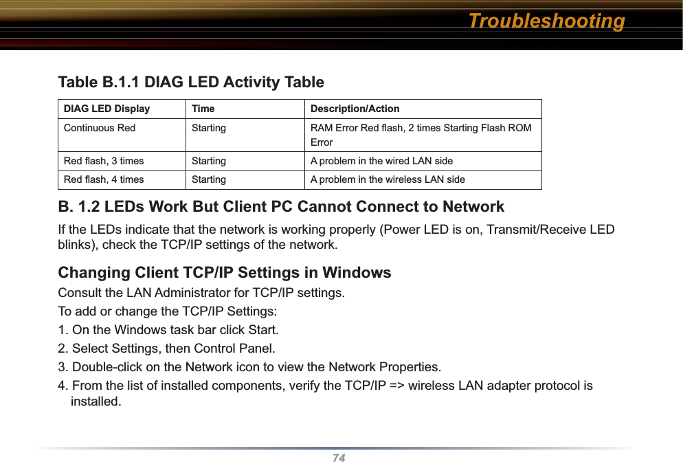
BUFFALO 04600142-0 AirStation Access Point User Manual WBR2 Manual indd

BUFFALO INC. AirStation Access Point WBR2 Manual indd

user manual

User ManualWireless Cable/DSL Router-GWBR2-G54www.buffalotech.com/wireless
2Introduction1.1 AirStation Broadband Router Base Station (WBR2-G54)Welcome to AirStation, the easy way to ultra fast wireless networking.This manual, which describes the most common confi gurations, introduces you to the AirStation Cable/DSL Router, and will help you connect to your network quickly.   The WBR2-G54 router, is a wireless 4-port router small/medium business (SMB) network device that complies with the 2.4GHz IEEE 802.11g standard specifi cation on wireless LANs.  The WBR2-G54 supports enhanced built-in NAT/SPI fi rewall functions and is used as a multi-functional router/link between wired and wireless LAN computers.  Summary of the AirStation WBR2-G54 features:•  Wi-Fi™ (Wireless Fidelity) certifi ed by the Wi-Fi Alliance as an 802.11b/g device.  AirStation will communicate with other IEEE 802.11b/g/Wi-Fi compliant wireless LAN products.•  Support for Wi-Fi Protected Access™ (WPA), 802.1x, TKIP, AES, and WEP.•  Automatic Transmit Rate Select mechanism transmits at speeds of 54, 36, 24, 11, 5.5, 2 and 1 Mbps.  •  Supports Frame Bursting for enhanced performance.•  DHCP client/server function.  •  Auto roaming, supports seamless roaming over multiple channels.•  VPN pass-through, for secure communications.•  Packet Filtering for eliminating unwanted communications.
3•  SOHO/SMB routing and fi rewall functions provide a safer private networking environment, includ-ing support for MS NetMeeting and MSN-Messenger. •  Additional SPI Firewall Functions - DMZ, intrusion detection and notifi cation•  Syslog transmits some or all system activities to a central Syslog server.•  Extended range, with optional add-on antennas or WDS (Wireless Distribution System).•  Auto Media Dependent Interface/Crossover (MDI/X) port, allows connection by standard and crossover CAT5 cables.•  Supports Universal Plug and Play (UPnP).•  Buffalo’s AOSS System for easy, secure wireless client confi guration.1.2 AirStation Wireless Network Features • Enhanced security features:-  SPI Firewall and DMZ zone functions to prevent unknown intruders.-  Intrusion Detector Firewall (NAT) with a pop-up or email alert warning unwanted attacks.- Dynamic packet fi ltering. -  WPA, 802.1x, TKIP, AES, and WEP.-  VPN (IPSec, PPTP and L2TP) pass-through-  Packet monitoring and fi ltering by MAC address, IP address and port.  - PPPoE supportIntroduction
4-  WDS support•  Buffalo’s easy web interface confi guration •  Broadband router static and dynamic routing methods between WAN and LAN based on updated routing tables.  An economical way to bridge multiple networks.•  Optional external antennas for boosting range and signal quality.•  Buffalo’s AOSS System for easy, secure wireless client confi guration.1.3 Home Networking 1For the future home entertainment applications that carry hard drives for storing hundreds of titles, IEEE 802.11g can transmit three channels of CD-quality voice to every room in the home simulta-neously.  Buffalo AirStation wireless access points enable sharing broadband by simply connecting the AirStation to a DSL or CATV modem  to:•  Share fi les and printers•  Access and share the Internet • Share media fi les1.4 SOHO/SMB NetworkingIntroduction
5With high-speed DSL or CATV connections readily available, many users can work effectively from a home offi ce, connected securely to a corporate network.  Buffalo’s solutions are ideal for home networks that require secure, high-speed access to the corporate LAN.  Tools that play an integral part in Buffalo’s solutions include VPN connectivity for secure access to corporate resources, which enable the remote employee to handle information from clients or coworkers as if they were in the offi ce.  Connect the Buffalo AirStation Broadband router AP to a CATV or DSL modem in order to:•Share broadband access•Share fi les and printers•Bridge between multiple networks  and multiple computer platforms•Provide easy and secure access to home or company networks from remote locations1.5 System RequirementsFigure 1.4 SOHO/SMB NetworkingIntroduction
6• Broadband (High-Speed) Internet connection or existing Local area connection• Any Wi-Fi (wireless) compatible computer with a Web Browser Internet Explorer or Netscape 4.5 or later. (Safari 1.0 is supported with Macintosh OS X.2)1.6 AirStation WBR2-G54 Package ContentsThe AirStation WBR2-G54 package consists of the following items. 1. WBR2-G54 Base Station2. AC adapter and power cable3. CAT5 LAN cable 4. Utility CD with Manual5. Quick Setup Guides6. Warranty StatementIntroduction
71.7 Product ViewsPower - Lit when the device is powered on.Wireless - Lit when the wireless radio is on.  Flashes when wireless traffi c is present.WAN - Lit when connection to Cable/DSL modem is present.  Flashes when internet traffi c is present.Diag - Flashes red when performing diagnostic functions.AOSS - Flashes when in AOSS mode.Ethernet - 1, 2, 3, or 4 lit when ethernet clients are connected.  Flashes when ethernet traffi c is present.IntroductionThe LAN or Wired MAC address is the default ESS-ID (SSID) of the AirStation. The LAN MAC address is clearly labeled on the back of the AirStation.
81.8 About the AirStation CD The AirStation does not require any software to be installed on your computer for confi guration. The AirStation CD contains client drivers for Buffalo Wireless Adapters (i.e. Notebook Adapter and Desktop PCI Adapter) and the AirStation documentation.Prior to copying or installing any software, please read the Software License Agreement “license.txt”, located in the root folder of the CD.  By installing, copying or using the AirStation software, you are consenting to the terms of this agreement. If you do not agree to all of the terms of the Software License Agreement, do not download, copy or install the AirStation software.It is the policy of Buffalo Technology to improve products as new technology, components, software and fi rmware become available.Please consult the AirStation wireless website (http://www.buffalotech.com/wireless) to download and install the latest fi rmware for your product. Introduction
9Follow these simple steps to connect the AirStation to your Broadband Internet connection allowing you to  combine and share wired and wireless computers and printers with the high-speed internet connection. 1. Power down the cable or DSL modem and the computer which will be used to confi gure the AirStation router.2. Plug the cable or DSL’s LAN Ethernet cable into the AirStation’s WAN port.  Initially, you may need to unplug this cable from your computer, hub or other router.3. Plug the provided Ethernet cable into a LAN port on the AirStation and plug the other end into your computer Ethernet adapter’s (NIC) port.  If you plan to initially confi gure the AirStation via a wireless connection, (not recommended), you may skip this step.4. Power on your cable or DSL modem, wait one full minute, Power on the AirStation router, wait another full minute and then power on the computer which will be used to confi gure the AirSta-tion.  If the red DIAG light on the AirStation is lit or fl ashing after several minutes of being pow-ered on, please consult Buffalo Technical Support.Installation / Setup
103.1 IntroductionConfi guring the AirStation using a standard web browser requires basic wireless confi guration knowledge. Setup includes manual wireless confi guration and basic administrative management. 3.2 Setup Preparation Make note of the AirStation’s wired MAC address (found on the back of the WBR2-G54).  It is also recommended you record any other broadband ISP information such as global IP address, subnet mask address, default gateway address, DNS server address and PPPoE parameters. 3.3 Setup Overview Buffalo recommends using a wired connection, meaning your computer is physically connected to the AirStation with a CAT5 straight cable plugged into one of the four LAN ports  This type of setup will eliminate possible setup problems due to any issues with the wireless adapter on the computer being used to confi gure the AirStation. A Web browser version 4.5 or later can be used to confi gure the AirStation. Advanced settings for security, fi ltering and other features will be explained in later sections. Standard Settings
11The WHR2-G54 has two internal antennas.  One has a vertical orientation while the other has a horizontal orienta-tion.  This setup is ideal because it allows for proper antenna polarization with both desktop and notebook style wireless adapter antennas.However, it may be necessary to increase your range further by installing an external, higher-gain antenna.  External antennas come in all shapes and sizes.  Antennas also come with different connectors.  The WHR2-G54 has an ‘MC Connector’ on it.  Thus, the antenna must also have an MC connector. To install the antenna, slide the antenna connector door on the back of the WHR2-G54 to the right.  This will expose the MC Connector.  Attaching the antenna is simple, just insert the antenna’s MC Connector into the WHR2-G54’s MC Con-nector and fi rmly push it in until it snaps into place.  Once snapped, the antenna’s connector will swivel with ease.  It is important not to push the antenna connector in at an angle.To remove the antenna, pull the antenna connector out.  It is important not to pull the antenna connector out at an angle.Antenna Installation
123.4 Open the Setup Screen  • Connect the WBR2-G54 according to the wiring instructions in Section 2.  • The WBR2-G54 has a default LAN IP address of 192.168.11.1 and Subnet Mask of 255.255.255.0.■ Note: The computer used to confi gure the AirStation should be set to obtain an IP address automatically using a DHCP server.  The Quick Setup Guide enclosed with the product contains detailed instruc-tions on how to confi gure your computer for initial confi guration.On the computer used to confi gure the AirStation, launch a Web Browser 4.5 or later.- Enter 192.168.11.1 into the URL fi eld.- A window will open prompting you to    enter a User ID and PasswordEnter “root” as the User ID and leave the password fi eld blank.■ Note:  These are the factory default settingsFig ure 3.4Initial Settings LoginStandard Settings
133.5 Enter ISP information  • Click the appropriate button to select the type of broadband access.  (Usrs more experienced in networking may choose to select the Ad-vanced button and skip to Section 4.)• For supplementary tools, use the tabs along the top of the screen.3.5.1 DSL ButtonSelect the appropriate connection method. Automatic IP Assignment by ISP - The DHCP server of the ISP assigns an IP ad-dress automatically.Fig ure 3.5Initial Settings ScreenFig ure 3.5.1Initial DSL buttonScreenStandard Settings
14Enter IP address manually- Enter the IP address given by the ISP.- Use ‘Enter IP address manually’ if the ISP requires use of a static IP address.PPPoE Connection- Enter the PPPoE information provided by the ISP. Fig ure 3.5.1aManual DSL IP Settings ScreenFig ure 3.5.1bDSL PPPoE Settings ScreenStandard Settings
153.5.2 CATV (Cable) ButtonSelect the appropriate connection method. Automatic IP Assignment by ISP - Select ‘Automatic IP Assignment by ISP’  if your ISP’s DHCP server assigns an IP address automatically.Enter IP address manually- Select ‘Enter IP address manually’ if the ISP requires use of a static IP address.Fig ure 3.5.2Initial CATV  Settings ScreenFig ure 3.5.2a Manual IP Address SettingsStandard Settings
16The IP address is acquired au to mat i cal ly but DNS server address is entered manually- Select ‘IP address is acquired automatically but DNS server address is entered manually’ if the ISP’s DHCP server supplies an IP address but not DNS server addresses.3.5.3 Line Test Tab Tests the connection to the Internet. Fig ure 3.5.2b Auto IP/Manual DNS SettingsFig ure 3.5.3 Line Test TabStandard Settings
173.5.4 Security TabThe Security Tab offers three Simple Security Settings. Follow the in struc tions in each screen to enter WEP keys, MAC Address Filtering and the degree of fi rewall security for the AirStation.Fig ure 3.5.4 Security TabStandard Settings
18Fig ure 3.5.4a Simple WEP Setup.-  Select the desired encryption and enter an appropriate WEP key to encrypt your network.  See the section on Wireless LAN Security starting on ‘Page 22’ for more information on encryption.Fig ure 3.5.4b Simple MAC Address Filter.- Select ‘Limit’ to use MAC fi lter-ing.  See ‘Page 30 for more infor-mation on MAC Address Filtering.Fig ure 3.5.4c Simple Security Setup.- See ‘Page 49’ for more information on Intrusion Detector.Standard Settings
193.5.5 Application TabThe Application Tab offers setup for special applications such as games, MS NetMeeting and MSN Messenger.  Follow the instructions in each screen. Although your AirStation will function fi ne using only the settings from Section 3, you may wish to explore more advanced options.  Chapter 4 explains each function in the Advanced settings area.  Fig ure 3.5.5Ap pli ca tion TabStandard Settings
20Fig ure 3.5.5a Web Gaming  Setup-Enter the ports(refer to Game documentation) the game runs on, and enter the Local IP Ad-dress of the PC that plays the game.Fig ure 3.5.4b NetMeeting Setup-Enter the IP Address of the PC that will use Netmeeting.Fig ure 3.5.4c MSN Messenger Setup-Refer to the on-screen help for information about Messenger.Standard Settings
21AOSSAOSS (AirStation One-Touch Secure System) is a simple, one-touch setup for connecting wireless clients to an access point while setting up the most secure possible connection.  Users no longer need to worry about choosing the proper security protocols, IP addresses, or ESS-ID's.  The intelligence of AOSS determines the most optimal connection and confi gures itself in seconds.■ NOTE: AOSS automatically creates a secure connection between your AOSS Access Point and client.  You must have a Buffalo AOSS enabled wireless client device to use the AOSS features of your AOSS Access Point/Router.◗  Confi gure your WBR2-G54's internet con-nection by referring to the instructions in the WBR2-G54's Quick Setup Guide.  ◗  Once the WBR2-G54 has been confi g-ured, follow the directions to install your wireless client device and its drivers if necessary.  Certain wireless client adapt-ers require client software to confi gure them.  If your device has a Client Man-ager, then install it as well.■ NOTE: If the  wireless client adapter is installed on a PC, then the AOSS client manager will need to be installed as well.  If your wireless client adapter is a standalone device that does not require a PC, then just power up the device.Standalone Devices:  Ethernet Converters and Access Point BridgesClient Manager Devices:  CardBus, USB, and PCI Adapters.Standalone AOSS DeviceClient ManagerDevice Client ManagerSoftware
22◗   Now that the WBR2-G54 and wireless client adapter are installed, you can use AOSS to confi gure them.◗   To begin the confi guration, press the AOSS button on the back of the WBR2-G54 for 3-5 seconds.  The AOSS light will begin to fl ash when the AOSS mode has been enabled.  You can stop pressing the button at this point.■ NOTE: AOSS mode will stay active for a period of two minutes.  This is the time-slot required to initiate the wireless client adapter.  The AOSS LED will stop fl ashing when AOSS mode has stopped or timed out.◗   Refer to your wireless client adapter's AOSS supplement to initiate the wireless client adapter's AOSS mode.◗  It typically takes 10-15 seconds for the AOSS light to stop fl ashing after the AOSS button has been pressed on the wireless client adapter.   Once confi guration is complete, the AOSS light will remain steady.  Please refer to your wireless client adapter's supplement for the remainder of the setup.AOSS
23Additional AOSS Information:◗  Only one AOSS wireless client adapter can be confi gured to the AOSS router at a time.  Thus, the button will need to be repressed for each additional AOSS wireless client adapter that will be connected.◗  It is not necessary to AOSS client devices that have already been confi gured via AOSS, unless signifi cant changes have been made to the wireless network.◗  Do not attempt to confi gure two separate AOSS networks at the same time, as it may cause undesired confi gurations.◗  If an undesired client has connected via AOSS, it can be disconnected from within the WBR2-G54's advanced confi guration menus.
24Click the Top tab and click the Advanced button.4.1 LAN Settings Set up LAN connections. 4.1.1 WirelessWireless Function - Enable or disable wireless LAN computer communication.ESS-ID (SSID) - Allows ad-ministrator to alter the ESS-ID of the AirStation.  To com-municate with a specifi c  AP only,  the AP’s ESS-ID must be entered in the client computer.  The client computer looks for the specifi c AP (or ESS-ID) for wireless communication.  Use up to 32 al pha nu mer ic characters for the ESS-ID (case sensitive).  By default the ESS-ID is the LAN Mac address of the AirStation.■ Note:  Roaming - When multiple AirStations have an identical ESS-ID, WEP key (if WEP is used), (and channel in WDS mode) , client computers may Roam between the AirStations. Wireless Channel  - Select the channel used for wireless communication.  There are 11 overlap-ping channels. Channels 1, 6 and 11 are non-overlapping.Advanced SettingsFig ure 4.1.1WirelessSettings
25If there are multiple APs in close proximity using the same channel, there may be interference.  In this case, change to a non-overlapping channel.Privacy Separator - Enable or disable communication between wireless clients.  If you choose to use this feature, every wireless client that is associated to the AirStation will not be able to commu-nicate with any other wireless clients. ■ Note: If this function is used, wired clients can still communicate with wireless clients. BSS (Basic Service Set) Basic Rate Set - The transmission data rates offered by the AirStation.  It is recommended to use the ‘Default’ selection to accomidate 802.11 and 802.11b rate sets.  It is NOT recommended to use the ‘All’ selection, as some devices may not understand all of the rate sets offered by the AirStation.Frame Bursting - This function increases 802.11b communication throughput by transferring pack-ets more effi ciently. The following conditions affect this function: • The wireless LAN client adapter must support Frame Bursting (and it must be enabled).  If the wireless LAN client adapter does not support Frame Bursting, or Frame Bursting is not enabled, then it will operate at non-Frame Bursting speeds.It is recommended to leave Frame Bursting enabled as it can only help throughput, not hurt it.DTIM Period - An access point transmits beacon signals to nearby clients at a preset interval.  This parameter sets the beacon transmission interval time (1-255 seconds). Se lec tion of a larger num-ber may conserve energy for the client computer (when client power management is enabled), but may delay wireless communication.  The default value of 1 is recommended. Advanced Settings
26Wireless output power - Confi gure output power of the AirStation. Decrease wireless output power to shrink the wireless communication range.  The default setting of 100% is recommended unless decreased range is desired4.1.2 Wireless LAN SecurityBroadcast SSID - Enable or Disable the SSID (ESS-ID) from being broadcasted. If denied,  the AirStation will not be found unless the specifi c AirStation’s SSID is entered in the client computer manually. Data Encryption - Disable to have no encryption of the wireless data.  This will make accessing the AirStation and the network very easy.  It is important to note, that without encryption it is easy for strang-ers to connect to your network, especially if the AirStation is broadcasting its SSID.Select the type of data encryp-tion:Fig ure 4.1.2Wireless Security SettingsAdvanced Settings
27• Disabled - Disable data encryption. - WEP - Uses WEP encryption. Encryption key should be entered. - TKIP - Uses TKIP (Temporal Key Integrity Protocol) for data encryption. The encryption key is renewed every “Re-key interval” when “TKIP”  is selected. WEP - When the WEP (Wired Equivalent Protection) encryption standard is implemented into a wireless network, a WEP key is used between the client and access point to successfully encrypt, transmit and decrypt data. For this reason, the same WEP key must be used for communication between the client and the AirStation. An access point and client may both carry multiple WEP keys. It is necessary for not only the WEP keys to match, but also the WEP key’s order. If a wireless client cannot support multiple WEP keys, the AirStations must be confi gured to transmit key number 1 for a connection to take place. Examples of WEP key:64-bit ASCII:  5 digits of alphanumeric characters, “ab34Y”128-bit ASCII:  13 digits of alphanumeric characters, “123456abcdef7”■ Note:  ASCII WEP keys are case sensitive.64-bit HEX:  10 digits, using characters 0-9 and a-f, “00234ABCDE”128-bit HEX:  26 digits, using characters 0-9 and a-f, “20123456789abcdeabcdeabcde” TKIP - TKIP (Temporal Key Integrity Protocol) is a WEP expanded encryption technique. TKIP has Advanced Settings
28greatly improved WEP’s weaknesses by rotating secret keys between every packet.  TKIP uses WPA-PSK (pre-Shared Key).AES - (Advanced Encryption Standard) is a next generation encryption technique discussed by the IEEE 802.11i committee for WPA2.TKIP improves WEP’s weakness, however AES also changes encryption method away from the weaker RC4 style.Throughput decreases 10 to 20 percent when TKIP software encoding is used. On the other hand, AES doesn’t decrease performance at all because it uses a hardware co-processor.TKIP Method - The TKIP method specifi es whether TKIP is processed via a software algorithm or through a hardware accelerator.  The hardware method has a limitation of 12 clients, the software client has a higher limitation of 50 clients.  It is recommended to use the hardware method unless more then 50 clients will be using TKIP at any given time.  The hardware method results in better wireless performance.Characteristics: - The Initialization Vector is expanded from 24-bits to 48-bits. - The Initialization Vector is randomized. - Uses a different RC4 key for every packet.  TIKIP requires an 8 to 63 character passphrase in ASCII or 64 digits hexadecimal key. Example 1: [ airstation -WPA-PSK ]Example 2: [0123456789abcdef0123456789abcdef0123456789abcdef0123456789abcdef]Advanced Settings
29WPA Group Rekey Interval - When TKIP is selected, the encryption key is renewed at this inter-val. This interval is in seconds; the range of acceptable values is 0-3600. If 0 is entered, the key is never renewed. ■ Note:  The lower the rekey interval, the more often a rekey occurs.  Setting a low rekey interval may affect performance negatively. IEEE802.1x/EAP authentication (WPA) - Confi gure Authentication and WPA Settings. Do not authorize - Do not use any RADIUS Server based authentication.Authorize - Authorized clients access this AirStation via RADIUS Server.Use 802.1x/EAP to authorize every wireless client who wants to access the AirStation by using 802.1x/EAP and a RADIUS Server.  The RADIUS server provides login information for every user establishing a more secure system than TKIP or other fi xed encryption key methods.  This also reduces the amount of necessary key maintenance. A RADIUS server is necessary for IEEE802.1x/EAP authentication. Enter [RADIUS Server], {RA-DIUS Port] and [RADIUS Key] information.  RADIUS authentication RADIUS Server - Enter RADIUS server IP address. RADIUS Port - Enter port number for authentication. RADIUS Key - Encryption key between RADIUS Sever and the AirStation. Enter the same key as registered in the server.  Use a 1 to 256 character alphanumeric code. Advanced Settings
304.1.3 LAN PortSet the LAN side Ethernet settings.LAN Side IP address  - Allows ad min is tra tor to specify a static IP and Subnet Mask for the LAN side of the AirStation.  ■ Note: If the AirStation’s IP address is changed, the con-fi guring computer’s IP must be changed to the same range to continue confi guration.  If the LAN IP is changed, restart the AirStation. (Section 4.4.10).  If the IP address is changed, then the DHCP scope must be changed to match.DHCP Server Function - Allows administrator to enable/disable the DHCP server function for the AirStation LAN side.  Select Use to enable and Do not use to disable the function.  Once Use is selected, the assigned IP address range can be specifi ed.  Enter the starting LAN IP address and total number of computers the DHCP server can accomidate. ■ Note: If there is another DHCP server on the network, one either must be disabled or the IP range must be changed to avoid confl icts derived from overlapping DHCP scopes. Figure 4.1.3LAN  Port SettingsAdvanced Settings
314.1.4 DHCP ServerAllows a more advanced con-fi guration of the DHCP server functions. DHCP Server Function - Al-lows ad min is tra tor to enable/disable the DHCP server func-tion for the AirStation LAN side. Select Use to enable or Do not use to disable this function. If the DHCP service is enabled, wireless and wired clients may receive IP addresses and other network information from the AirStation.  If the DHCP server is turned off, all client PC’s must have unique, static IP addresses and valid network settings manually entered. Check with your LAN administrator for static IP information.Assigned IP address (Range As sign ment) - Sets the beginning address and range of addresses to be assigned by the AirStation’s DHCP server function.  Select up to 253 consecutive addresses (nodes).  The IPs to be excluded from the range spec i fi  ca tion should be entered in the specifi ed fi eld. Figure 4.1.4 DHCP Server SettingsAdvanced Settings
32Lease duration - Specifi es the time in hours (1-999) an assigned IP address is valid. If the client computer does not request a renewal of IP address before the lease period expires, the AirStation can issue the IP to another client computer.Default Gateway  - Allows administrator to use the Default Gateway address (the AirStation’s IP address), assign a specifi c Gateway address, or block clients from Gateway notifi cation. DNS server - Allows administrator to use the default DNS address (the AirStation’s IP address), assign specifi c DNS addresses, or block clients from DNS address notifi cation. WINS server - Allows administrator to use a WINS address.  Select auto assignment of the IP ad-dress, enter a specifi c WINS IP address, or block clients from the WINS address notifi cation. Domain name - Allows administrator to use an assigned domain name, assign a specifi c domain name, or block clients from domain name no ti fi  ca tion.  Domain names will be sent to LAN comput-ers when an IP address is assigned.  Enter a maximum of 64 al pha nu mer ic characters. Advanced Settings
33Manual IP and MAC Address As sign ment - Allows adminis-trator to add additional leased IP addresses tied to a specifi c MAC address.  When a spe-cifi c MAC address connects to the AP, the IP address speci-fi ed will be given to that client. Display/Delete lease informa-tion - List of IP addresses, MAC addresses, lease periods and status is displayed. Figure 4.1.4bManual IP and MAC Address Assignment SettingsAdvanced Settings
344.1.5 Wireless MAC FilterWireless PC’s Connection - Select Limit to restrict wireless connections to the registered adapters in the list.  Select Do not limit to disable MAC ad-dress fi ltering. Figure 4.1.5b Wireless MAC FilterAdvanced Settings
35Register for allowable PC’s MAC address - MAC access restriction set up in LAN.  Input the MAC addresses that are allowed to communicate with the AirStation.MAC address list - Displays a table list of all MAC addresses allowed to communicate with the AirStation.Advanced SettingsFigure 4.1.5b Register for Allowable PC’s MAC Address
364.1.6 Wireless Bridge (WDS)The Wireless Distribution System supports peer-to-peer AP communication. Wireless Bridge (WDS) Func-tion - Select Enable to allow Bridge (WDS) mode between AirStations or Disable to block communication between AirStations. Wireless Bridge (WDS) dedi-cated mode - Select Enable to restrict wireless computer com-munication with the AirStation.  In dedicated mode wireless clients CANNOT connect to WDS AirStations.■ Note: All AirStations must support WDS and be on the same channel.  For roaming support, use the same SSID on all devices.Add AirStation (wireless MAC Address):  Allows administrator to input the wireless MAC address of AirStations for Bridge (WDS) communication. The wireless MAC address  is found in the Man-Advanced SettingsFigure 4.1.6 Wireless Bridge (WDS) Settings
37agement section => System Information, labeled wireless MAC address. To enable WDS, set the Wire-less Bridge (WDS) function to Enable. Enter the Wireless MAC address of the AirStation to communicate with in the form of two characters separated by a colon and click Add.  MAC Address Ex: 00:00:00:00:00:00Up to six AirStation MAC ad-dresses may be registered. Click Apply under Wireless Bridge (WDS) settings when the wireless Mac addresses AirStation are entered.Repeat this process on every other AirStations used in Bridge (WDS) mode.Figure 4.1.6b Wireless Bridge (WDS)SettingsAdvanced Settings
384.2 WAN Settings 4.2.1 WAN Port Communication Method of Wired WAN - Select port speed and type of duplex connecting to the WAN port.  If unknown, select Auto negotiation. MAC Address of WAN - Set the AirStation MAC address to be used for WAN com mu -ni ca tion.   Some ISP’s may require you to set the MAC Ad-dress of WAN to be the same MAC address of your cable or DSL modem.IP Address of WAN - Allows administrator to select DHCP server, PPPoE, or manual setting for the WAN port of the AirStation.  Auto IP assignment from DHCP server - acquire the IP address automatically from the DHCP server.Use PPPoE client - If selected, the in for ma tion listed below must be entered.Manual setting - Enter the appropriate IP address and subnet mask. Figure 4.2.1 WAN port SetupAdvanced Settings
39PPPoE Setting (for enabling PPPoE Client function) - Allows administrator to use PPPoE as specifi ed by the ISP. The following parameters should be entered for PPPoE Settings:Name of Connection - Enter the name of your connection.User Name - Enter the user name (up to 64 alphanumeric characters) for PPPoE au tho ri za tion.Password - Enter the password provided by your ISP (up to 64 alphanumeric characters).  Reenter the password in the Confi rmation box.Service Name - Enter the PPPoE service name (up to 64 alphanumeric characters).  If your ISP doesn’t require a service name, then leave it blank.Connection Type - Select from:- Continuous Connection - connects im me di ate ly after setting and never   disconnects.- Connect on Demand - Reconnects when the disconnect time elapses.- Manual - Disables Automatic Con nec tion.  Connects to the Internet using  the connect button on the initial settings page.  The Enter New Connection button will not appear until Use PPPoE Client is set.Disconnection Time - Specify the number of minutes (0-1440) before automatic dis con nect is performed.  If “0” is entered, the dis con nect function is disabled.  If Con tin u ous Connection is selected, the timer is disabled.Advanced Settings
40Authorization - Authorization method for accessing the ISP’s PPPoE server.  If unknown, select Auto authorization.MTU (Maximum Transmit Unit) Size - Maximum Transmit Unit (578-1492) when using PPPoE. MRU (Maximum Receive Unit) Size - Maximum Receive Unit (578-1492) when using PPPoE. Keep Alive - Enables the PPPoE client to send a Link Control Protocol (LCP) echo request to the PPPoE server once per minute.  If there is no reply within six minutes, the client disconnects.  Set to Disable if frequent disconnection occurs. Activation - Enable/disable registered connection settings. If disabled, the connection is not per-mitted.Figure 4.2.1a PPPoE SettingsScreenAdvanced Settings
414.2.2 Network of WANWAN side (Internet) param-eters.  These settings are gen-erally not required if your ISP is providing DHCP services.  In this case these fi elds can be left blank if desired.Host Name - Enter the host name as desired. Default Gateway  - A default gateway IP should be assigned to the AirStation.  If unknown, leave blank.  If Auto IP as sign ment from DHCP Server is selected in Section 4.2.1, a gateway IP is assigned automati-cally, provided the DHCP server is set to provide one. DNS Server Address - Enter the primary and secondary DNS address(es) of the server to be used by the AirStation for DNS resolution. If DNS was set to Do not use (Section 4.1.4), leave blank.  If Auto IP as sign ment from DHCP Server was selected, DNS addresses are assigned automatically, provided the DHCP server is set to provide them. Fig ure 4.2.2  Network of  WAN Advanced Settings
42Port Number for WEB Settings - Set a specifi c port number when remote setup of the AirStation is planned.  Using port 80 allows the AirStation to be accessed from the internet by connecting to http://xxx.xxx.xxx.xxx (where xxx.xxx.xxx.xxx is your WAN IP address).  You will need to confi gure the NAT (Section 4.32) to forward PORT 80 back to the AirStation.PING from WAN - Allows a PING test from the WAN/Internet.  Select Do not respond or Re-spond. Advanced Settings
434.3  Network Setting 4.3.1 Routing SetupRIP transmission to WAN - Allows RIP transmission or None (no RIP) to WAN RIP reception from WAN - Al-lows RIP reception or None (no RIP) from WANRIP transmission to LAN - Al-lows RIP transmission or None (no RIP) to LANRIP reception from LAN - Al-lows RIP reception or None (no RIP) from LANRIP transmission to WAN - Allows RIP transmission or None (no RIP) to WANDisplay current information - Allows administrator to view and delete routing information. Click Add Route to Add a Routing Table Entry  •Destination address - Network IP address and subnet mask.Fig ure 4.3.1 Routing SetupAdvanced Settings
44• Gateway - Address through which the packet passes be-fore it reaches the des ti na tion address.• Metric - Number of routers (1-15) to be passed before the packet reaches its destination. Fig ure 4.3.1b Add Routing Table EntryAdvanced Settings
454.3.2 Address Translation  Address Translation - Select Use or Do not Use.  Address Translation must be enabled for client computers to connect to the Internet.  Selecting Use enables the following func-tions:  • IP Masquerade - When the LAN computer connects to the WAN side, the IP address of LAN computer is dynamically translated to become the WAN IP address of the AirStation.  Multiple LAN computers can share one WAN IP address to access the Internet.• Static IP address translation -When the WAN requests connection to the LAN, the WAN IP address of the AirStation is translated into the IP address of the LAN computer. Fig ure 4.3.2 Address Translation SetupAdvanced Settings
46Log Output - Set ‘Log Output’ to log discarded packets.  Otherwise, a dropped packed is not logged.IP address of DMZ - Allows administrator to set the DMZ (De-Militarized Zone) address. Incoming packets containing no recognizable destination port information will be re di rect ed to the DMZ’s IP address.  Display/Delete NAT Table  - Allows ad min is tra tor to delete NAT tables. Add NAT TableGroup - Specify a group (up to 16 characters) that the NAT rule belongs.   Groups are sim-ply used to visually organize the NAT table for the admin-istrator.  It is recommended to name the group after the protocol that is being setup (e.g. Group Name FTP when setting up address translation for FTP)Click New Group to create new group or select an existing group to add a NAT rule to it. IP address of WAN - Select AirStation’s IP address of WAN or Manual setting.  For Manual set-ting, enter the IP address used by the WAN computer to connect to the local computer.  Fig ure 4.3.2b Address Translation SetupAdvanced Settings
47AirStation’s IP address of WAN should be used unless you have multiple WAN side IP addresses.  Some network applications (online games or streaming software) require adding Address Transla-tion tables; consult the software’s documentation for port information).Protocol (WAN):•  All - Selects all IP protocols.•  ICMP - Network Diagnostic Protocol (1).•  Manual - Specify the protocol number (0-65535).•  TCP/UDP - Enter port number for TCP or UDP protocols.  If both TCP and UDP are required, then separate entries are required.IP address of LAN - Select Manual and enter the destination IP address of the LAN computer; or select AirStation’s IP address of LAN.  AirStation’s IP address of LAN should be used when setting up the port for web setting (Section 4.2.2).  For the web setting, forward a TCP port (typi-cally port 80) from AirStation’s IP address of WAN to the same TCP port for AirStation’s IP address of LAN.Protocol (LAN) - Enter destination port number.  If left blank, the packets are transferred to the same port number as the source port number.  Typically the destination port should be left the same as the source port.• Click Add to NAT table.  This will add the information to the NAT table.  Once you have gone through this process for every desired translation, you will need to press the Apply button on the top of the screen to start the translating.Advanced Settings
484.3.3 Packet Filter Log Output - Select Output to activate the packet fi lter log. Packet Filter Information Basic Rule - Click add/delete basic rules. Place a check mark next to the basic rule to enable: • Prohibit setup from wire-less LAN - Prohibits adminis-tration from a wireless com-puter. • Prohibit setup from wired LAN - Prohibits administration from a wired computer. • Prohibit setup via wireless bridge access point - Prohibits a personal computer connected to another AirStation in a wireless bridge. • Prohibit NBT and Microsoft-DS routing - Prevent unexpected external access via Microsoft network sharing.  This prohibits computers on the internet from accessing shared resources on Windows machines.  It is recommended to leave this fi lter activated.• Reject the IDENT request - The AirStation sends reject packets if it receives an IDENT request.  Figure 4.3.3 Packet Filter SetupAdvanced Settings
49Use this fi lter when the com-munication speed goes down using a network application like E-mail, FTP and WEB. * If IDENT requests are for-warded to a LAN side client by address translation setting (DMZ or TCP port :113 ), this basic rule is ignored. IP Filter setting - Limits the type of packets allowed to pass between the WAN and LAN. The maximum number of rules is 32.   • Operation - Packets from WAN (or LAN), select ignored, rejected, or accepted.  Select the operation to be performed on the packets. Packets from:• WAN side - packets coming from the WAN side will be fi ltered. Figure 4.3.3a Basic Filter SettingAdvanced Settings
50• LAN side - packets from the LAN side will be fi ltered. Are :• Ignored - Stop the packet and do not route it. • Rejected - Return the rejected packet to the point of origin. •  Accepted - Pass the packet through. • Destination IP Address - The IP address to be fi ltered.• Source IP Address - The IP address designated for fi ltering. If all IP addresses must be fi ltered, leave this box blank. Warning: If administrator selects packet from LAN is Ignored or Rejected, the ad min is tra tor will no longer have access to the AirStation confi guration screens.  This function prohibits setup from a wireless or wired computer.  The AirStation can be returned to the factory default settings by holding down the INIT button on the back of the unit for fi ve seconds or until the red DIAG light becomes solid. Protocol  - Mark and select a specifi c protocol.  Select from all protocols, ICMP, arbitrary protocol number and TCP/UDP protocol number.Figure 4.3.3b IP Filter settingAdvanced Settings
51•  All - Selects all IP protocols.•  ICMP - Network Diagnostic Protocol (1).•  Manual - Enter protocol number (0-65535).•  TCP/UDP Destination Port - Select TCP or UDP, then enter port number. Priority - Specify the priority  an item.  The smaller the number, the higher the priority. MAC Filter - Click Enter MAC fi lter to enter MAC address.Source MAC address -The MAC address of the source of the packets that will be fi ltered may be set. Click Add rule when complete.■ Note:  If confi guring from a wireless computer, add your MAC address to the list of au tho rized wireless LAN PCs.  The MAC address must be in two-digit groups separated by colons.Example:  00:40:26:00:11:22 Click Apply when settings are complete.Advanced SettingsFigure 4.3.3c Add MAC Filter setting
524.3.4 Intrusion DetectorThe Intrusion Detector watch guards and prevents unauthorized access from the WAN (Internet)This function also records information on unauthorized access attempts  Intrusion Detector - Select Do not use, Use or Use (Apply Packet fi lter setting for Intrusion Detector setting).  IP Spoofi ng - Check Block to prevent IP spoofi ng.Threshold Value - Enter the number (1-999) of suspect packets before the notifi cation occurs.Notify by email • Notifi cation email address - Enter des ti na tion email address• Sender email address - Enter the email address that will send the email.  This is the name that will appear as the sender when the email is read.  This email can be made up (e.g. DETECTOR@AIRSTATIONAdvanced Settings
53• Sender email server address - En-ter the SMTP Server address.• Receiving email server au tho -ri za tion - Enter the POP3 Server address, User name and Password.  This is only required if your SMTP server requires POP verifi cation before it allows email to be sent.  Con-sult your ISP or mail server support for more information.• Send test - Click Send to test no ti -fi  ca tion; this will also save and commit the entries.Pop-up notifi cation - Pop-up window alert of unwanted activity. Client Man-ager must be installed and running on a client machine to use this feature.• Destination IP address - Enter the IP address to be notifi ed.  The LAN computer with this IP address must have Buffalo’s Client Manager software installed and running for the verifi cation to occur.  If the machine is off the verifi cation will not be received, and the AirStation will NOT resend information.Intrusion Detector information - displays log activity detected by the Intrusion Detector service.Figure 4.3.4 Intrusion Detector SetupAdvanced Settings
544.3.5 UPnP Select Use to enable UPnP (Universal Plug and Play).  When a computer with UPnP support connects to the AirSta-tion, that computer automati-cally receives confi guration information from the AirStation. Advanced SettingsFigure 4.3.5 UPnP Setting
554.4 Management (Network Diagnosis Settings) 4.4.1 System InformationSystem information of the AirStation is obtained here.• Model name - Displays model and fi rmware version • AirStation Name - Displays AirStation host name• DHCP Server function - Displays On or Off • Wireless - Displays the wireless LAN settings such as wireless MAC address and wireless fi rmware.  The wireless MAC address is required for setting up WDS with other access points.  This is the best place to determine the wireless MAC address.• LAN - Displays the AirStation LAN settings  • WAN - Displays the AirStation WAN settingsAdvanced SettingsFigure4.4.1 SystemInformation
56• Default Gateway - Displays the default gateway settings • WAN side IP address auto acquisition - This is the method to acquire the IP address from the WAN (Internet) side DHCP server.   Press Release to release current DHCP WAN information.  Press Renew to obtain WAN information from the DHCP server.  NOTE:  If a manual IP is assigned to the WAN port, this feature is not displayed.4.4.2 Name and Pass-word AirStation name - When using multiple AirStations, select a unique name to make it eas-ier to identify each AirStation through the AirStation Manager utility.  This utility is seldomly used, thus, the AirStation name value has little value.Administrator name - “root”, cannot be changedAdministrator password - Allows the administrator to en-ter an administrator password to restrict access to the setting screens.Advanced SettingsFigure 4.4.2 Name and Password Setup
57• New Password - Enter new password.  Enter up to eight alphanumeric characters (case sensi-tive)• Confi rm Password - Reenter the new password for confi rmation  4.4.3 Time setupTime setup - Enter the current date and time, and click Set.NTP - Network Time Protocol. Select Use or Do not use.■ Note: If NTP is used, time is set au to mat i cal ly.  NTP server name - Enter the NTP server nameCheck Interval - Enter the time interval (in hours) for the time check frequencyTime Zone - Select local time zone Click Set.Advanced SettingsFigure 4.4.3 Time Setup Screen
584.4.4 Transfer Packet ConditionDisplays number of packets sent and received for:Wired WANWired LAN Wireless LAN  Click Refresh to start update the transfer packet log.Advanced SettingsFigure 4.4.4 Transfer PacketCondition
594.4.5 Client MonitorDisplays the wired and wireless clients (computers) that are accessing the AirStation.• MAC address  - Shows the client’s MAC address. • Leased IP address  - Shows the IP address that is assigned to the client from the DHCP server. The network medium is indicated as wireless or wired depending on how the client is accessing the AirStation. ■ Note:    The Client Monitor only shows clients that have received an IP address from the AirStation’s DHCP server.  Clients that have static IP addresses will not appear in the Client Monitor.Advanced SettingsFigure 4.4.5 Client MonitorScreen
604.4.6 PING Test Performs a PING test from the AirStation to a LAN or WAN address. Enter the target IP address and click OK (e.g. 192.168.11.2 - OR- www.buffalotech.com)If the test results in an error, then verify you correctly inputted the address and check your connections.Advanced SettingsFigure 4.4.6 PING Test
614.4.7 Log InformationDisplay log info level - Select Error and/or Notify to spec-ify the types of reports to be logged by the AirStation.Display log info - Select the specifi c reports to be logged.Log information - Displays recorded logs. Advanced SettingsFigure 4.4.7 LogInformation Screen
624.4.8 Syslog transmittingSelect Use or Do not use to enable or disable the AirStation’s ability to transmit information to a Syslog server.  • Syslog Server - Enter the IP address of the Syslog server.• Log Information Level - Select Error and/or Notice to specify the types of reports to be sent to the Syslog server. • Log Information - Select the specifi c reports to be sent to the Syslog server. ■ Note:  A server on the net-work running a Syslog service is required for this. Advanced SettingsFigure 4.4.8 SyslogTransmittingScreen
634.4.9 Save/Restore SettingsSave current settings - Click Save to open the fi le saving dialog and save the current AirStation settings to a fi le. Restored saved settings - Restores settings from a fi le that has been saved. Click Choose fi le to select the saved fi le and click Restore. ■ Note: If the setting fi le is saved by a newer fi rmware than the current one, the AirStation can’t restore the settings. Advanced SettingsFigure 4.4.9 Save/RestoreSettingsScreen
644.4.10 Initialization/RebootClick Restart to reboot AirStationClick Restore to reset the AirStation to default factory settings. ■ Note: Resetting to default factory settings will erase all settings and passwords previously entered.  The AirStation will return to the condition it was in when fi rst purchased.Advanced SettingsFigure 4.4.10 Initialization/Reboot
654.4.11 Firmware Update Firmware fi le name - Click Browse to browse to the path and fi lename for the new fi rm-ware. Click Firmware Update to load fi rmware to the AirStation.■ Note: Firmware update does not erase current user settings. Please visit the Buffalo Tech-nology Web Page to download the latest fi rmwares free of charge.  http://www.buffalotech.com/wirelessAdvanced SettingsFigure 4.4.11 Firmware Update
66Additional InformationFor more information, please consult:• The AirStation website at:   http://www.buffalotech.com - for frequently asked questions (FAQ’s) and Software Updates. Advanced Settings
674.4.12 AOSS Status - Click refresh to refresh the status of the AirStation’s AOSS sessions.AOSS Function - Click Enable to allow the AirStation to use AOSS function.  Click Disable to shut off the AOSS system.  Clicking Disable will disable the AOSS button on the AirStation.Launch AOSS - Click Launch AOSS to begin the AOSS se-quence.  This starts the AOSS process just like pressing the AOSS button.Reset - Click Reset to release the AOSS information, including encryption keys.Figure 4.4.12 AOSSAdvanced Settings
68WBR2-G54 BASE STATION SPECIFICATIONSPhysical Specifi cations Dimensions W3 x H6.75 x D6.1in. (76 x 171 x 155mm)Weight 1 lb. (620g)Temperature & Humidity Operation 0˚ to 40˚ C Maximum humidity 80%Transit/Storage 0˚ to 40˚ C maximum humidity 80% (no condensation) Power CharacteristicsTransmit Mode 1.1A (Nominal), Power Supply 3.3 V Regulatory InformationWireless communication is often subject to local radio regulations. Although AirStation wireless networking products have been designed for operation in the license-free 2.4 GHz band, local radio regulations may impose limitations on the use of wireless com mu ni ca tion equipment. Specifi cations
69Networking CharacteristicsCompatibility •  IEEE802.11g/b Standard for Wireless LANs •  Wi-Fi (Wireless Fidelity) certifi ed by the Wi-Fi Alliance.Host Operating SystemMicrosoft Windows® 98SE/ME/NT4.0/2000/XP, Unix, Linux and MacOSMedia Access ProtocolWired - CSMD/CD (Collision Detection) Wireless - CSMD/CA (Collision Avoidance) with Acknowledgment (ACK) Radio CharacteristicsRF Frequency Band 2.4 GHz (2400-2483 MHz)11 selectable channels (3 non-overlapping)Modulation Technique Direct Sequence Spread Spectrum• ODFM for High Transmit Rate• DQPSK for Standard Transmit Rate• DBPSK for Low Transmit RateSpecifi cations
70Spreading 11-chip Barker SequenceNominal Output Power 13.5 dBmTransmit Rate / RangeHigh Speed 54 MbpsMedium Speed 36 MbpsStandard Speed 2 MbpsLow Speed 1 MbpsOpen Offi ce Environment 160 m (525 ft.)270 m (885 ft.)400 m (1300 ft.)550 m (1750 ft.)Specifi cations
71Semi-Open Offi ce Environment50 m (165 ft.)70 m (230 ft.)90 m (300 ft.)115 m (375 ft.)Closed Offi ce 25 m (80 ft.)35 m (115 ft.)40 m (130 ft.)50 m (165 ft.)Receiver Sensitivity -83 dBm -87 dBm -91 dBm -94 dBm (depends on data rate)Delay Spread (at FER of <1%) 65 ns 225 ns 400 ns 500 ns (depends on data rate)•   The range of wireless devices can be affected by metal surfaces, solid high-density materials and obstacles in the signal path. Table “Radio Characteristics” lists the typical ranges when used indoors:•   In Open Offi ce environments, clients can “see” each other, i.e. there are no physical obstruc-tions between them.Specifi cations
72•   In Semi-open Offi ce environments, work space is separated by room dividers; client cards are at desktop level.•   In Closed Offi ce environments, workspace is separated by fl oor-to-ceiling brick walls.■ Note: The range values listed in Table “Radio Characteristics” are typical distances as measured at Buffalo Technology AirStation laboratories. These values are provided for your guidance but may vary according to the actual radio conditions at the location where the AirStation product is installed. AirStation IEEE 802.11 Channel Sets The range of the wireless signal is related to the Transmit Rate of the wireless communication. Communications at a lower Transmit range may travel longer distances. Center Channel ID FCC1 2412  2 2417  3 2422  4 2427  5 2432  6 2437  7 2442  8 2447  9 2452  10 2457  11 2462 11  default channel Specifi cations
73Common Problems:• Out of range, client cannot connect to the AirStation.• Confi guration mismatch, client cannot connect to the AirStation.• Absence or confl ict with the Client Driver.• Confl ict of another device with the AirStation hardware. B.1.1 LED Activity B Monitoring LED activity helps identify problems.  •  Power LED should be GREEN,•  Wireless LED should be GREEN if the line is active.  If is it blinking GREEN, wireless communica-tion is active.•  Ethernet LED should be GREEN (100Mbps) or AMBER (10Mbps) while the communication is ac-tive. DIAG LED ActivityUnplug the power for three seconds. Plug the power back in to monitor the DIAG LEDs during start-up. If any symptoms match section B.1.1, call the Buffalo Tech Support line 24 hours a day, 7 days a week at 866-752-6210 or email info@buffalotech.com. Troubleshooting
74Table B.1.1 DIAG LED Activity TableDIAG LED Display Time Description/ActionContinuous Red  Starting  RAM Error Red fl ash, 2 times Starting Flash ROM Error Red fl ash, 3 times  Starting  A problem in the wired LAN side Red fl ash, 4 times  Starting  A problem in the wireless LAN side B. 1.2 LEDs Work But Client PC Cannot Connect to Network If the LEDs indicate that the network is working properly (Power LED is on, Transmit/Receive LED blinks), check the TCP/IP settings of the network. Changing Client TCP/IP Settings in WindowsConsult the LAN Administrator for TCP/IP settings.  To add or change the TCP/IP Settings:1. On the Windows task bar click Start.2. Select Settings, then Control Panel.3. Double-click on the Network icon to view the Network Properties.4. From the list of installed components, verify the TCP/IP => wireless LAN adapter protocol is installed.Troubleshooting
75•   If the wireless adapter protocol is not yet installed, click the Add button and select the TCP/IP protocol from the list. Refer to Windows Help for more information.•   If the wireless adapter protocol is installed, select the protocol and click the Properties button.  Verify the parameters match the settings provided by your LAN Administrator.  Make changes if necessary, and click OK.5. When or if prompted, restart your computer. B. 1.3 Other Problems Please refer to www.buffalotech.com for further reference materials. Troubleshooting
7610BaseT or 100BaseTx:  802.3 based Ether-net network that uses UTP (Unshielded twisted pair) cable and a star topology.  10 is 10 Mbps and 100 is 100 Mbps. 802.1x: The standard for wireless LAN authenti-cation used between an AP and a client.  802.1x with EAP will initiate key handling. Ad-Hoc Network: The wireless network based on a peer-to-peer communications session.  Also referred to as AdHoc. Bandwidth:  The transmission capacity of a computer or a communication channel, stated in Megabits per second (Mbps). BSS (Basic Service Set):  An 802.11 network-ing framework that includes an Access Point. Bus Mastering:  A system in which the speci-fi ed Input/Output device (e.g. NIC Card) can perform tasks without the intervention of the CPU. Client:  A PC or workstation on a network. Cross-Over Wiring: A UTP cable that has its transmit and receive pair crossed to allow com-munications between two devices. DCE (Data Communications Equipment):  Hardware used for communication with a Data Terminal Equipment (DTE) device. Default Gateway: The IP Address of either the nearest router or server for the LAN. Default Parameter: Parameter set by the manufacturer. Destination Address: The address portion of a packet that identifi es the intended recipient station. DHCP (Dynamic Host Confi guration Pro-tocol): Based on BOOTP, it uses a pool of IP addresses, which it assigns to each device con-nected to it, and retrieves the address when the device becomes dormant for a period of time. DNS (Domain Name System):  System used to map readable machine names into IP ad-dresses Glossary
77Driver:  Software that interfaces a computer with a specifi c hardware device. DSSS (Direct Sequence Spread Spectrum): Method of spreading a wireless signal into wide frequency bandwidth. DTE (Data Terminal Equipment):  Device that con10BaseT or 100BaseTx:  802.3 based Ethernet network that uses UTP (Unshielded twisted pair) cable and a star topology.  10 is 10 Mbps and 100 is 100 Mbps. Dynamic IP Address:  An IP address that is automatically assigned to a client station in a TCP/IP network, typically by a DHCP server. ESS (Extended Service Set):  A set of two or more BSSs that form a single sub-network.  ESS-ID is user identifi cation used in the ESS LAN confi guration. Ethernet: The most widely used architecture for Local Area Networks (LANs). It is a shared-media network architecture. The IEEE 802.3 standard details its functionality. Ethernet cable: A wire similar to telephone cable that carries signals between Ethernet devices. File and Print Sharing: A Microsoft application that allows computers on a network to share fi les and printers. Firmware: Programming  inserted into pro-grammable read-only memory, thus becoming a permanent part of a computing device. Frame: A fi xed block of data, transmitted as a single entity.  Also referred to as packet. Full-Duplex:  To transmit on the same channel in both directions simultaneously. Half-duplex: To transmit on the same channel in both directions, one direction at a time. Hub:  A device which allows connection of com-puters and other devices to form a LAN.  IEEE (Institute of Electrical and Electronics Engineers):  The professional organization which promotes development of electronics technology.  Glossary
78IP (Internet Protocol) Address:  A unique 32-binary-digit number that identifi es each sender or receiver of information sent in packets. Infrastructure:  A wireless network or other small network in which the wireless network devices are made a part of the network through the Access Point. ISP (Internet Service Provider):  A company that provides access to the Internet and other related services. IV (Initialization Vector):  The header section of an encrypted message packet. LAN (Local Area Network):  A group of com-puters and peripheral devices connected to share resources. LED (Light Emitting Diode):  The lights on a hardware device representing the activity through the ports. MAC (Medium Access Control) Address:  A unique number that distinguishes network cards. Mbps (Mega Bits Per Second):  A measure-ment of millions of bits per second. MDI/X (Media Dependent Interface/Cross-over):  Port on a network hub or switch that crosses the incoming transmit lines with the outgoing receive lines. MHz (MegaHertz):  One million cycles per second. NAT (Network Address Translation):  An inter-net standard that enables a LAN to use one set of IP addresses for internal traffi c and a second set for external traffi c. NIC (Network Interface Card):  An expansion card connected to a computer so the computer can be connected to a network. Packet:  A block of data that is transferred as a single unit, also called a frame or a block. Packet Filtering:  Discarding unwanted net-work traffi c based on its originating address or its type. Glossary
79mation between computers. RADIUS (Remote Authentication Dial In User Service):  A server that issues authentication key to clients. RAM (Random Access Memory):  Non-permanent memory. Repeater Hub:  A device that collects, strengthens and transmits information to all connected devices, allowing the network to be extended to accommo-date additional workstations. RC4:  The encryption algorithm that is used in WEP.  RJ-45 connector:  An 8-pin connector used be-tween a twisted pair cable and a data transmission device. ROM (Read Only Memory):  Permanent memory. Router:  Device that can connect individual LANs and remote sites to a server. Roaming:  The ability to use a wireless device while moving from one access point to another without losing the connection. PCI (Peripheral Component Interconnect):  A bus that is connected directly to the CPU. PCMCIA (Personal Computer Memory Card International Association) Card:  Remov-able module that adds features to a portable computer. Ping (Packet Internet Groper):  An Internet utility used to determine whether a particular IP address is online. Plug and Play:  Hardware that, once in-stalled (“plugged in”), can immediately be used (“played”), as opposed to hardware that requires manual confi guration. PoE (Power over Ethernet):  A mechanism to send DC power to a device using a CAT5 Ethernet cable. PPPoE (Point-to-Point Protocol over Ether-net):  A specifi cation for connecting users on an Ethernet line to the Internet through a common broadband medium. Protocol:  A standard way of exchanging infor-Glossary
80Script:  A macro or batch fi le containing instruc-tions and used by a computer to perform a task. Server:  Any computer that makes fi les or peripheral devices available to users of the network and has a resident Network OS. SMTP (Simple Mail Transfer Protocol):  The protocol used to defi ne and deliver electronic mail (E-mail) from one location to another. SNMP (Simple Network Management Proto-col:  An application layer protocol that outlines the formal structure for communication among network devices. Static IP Address:  A permanent IP address is assigned to a node in a TCP/IP network.  Also known as global IP.  STP (Shielded Twisted Pair):  Twisted Pair cable wrapped in a metal sheath to provide ex-tra protection from external interfering signals. Subnet Mask:  An eight-byte address divided into 4 parts separated by periods. TCP/IP (Transmission Control Protocol/In-ternet Protocol:  Protocol used by computers when communicating across the Internet or Intranet. TKIP (Temporal Key Integrity Protocol):  An encryption method replacing WEP.  TKIP uses random IV and frequent key exchanges. Topology:  The shape of a LAN (Local Area Network) or other communications system. Twisted Pair:  Cable that comprises 2 or more pair of insulated wires twisted together. UDP (User Datagram Protocol):  A com-munication method (protocol) that offers a limited amount of service when messages are exchanged between computers in a network.  UDP is used as an alternative to TCP/IP. Uplink:  Link to the next level up in a communi-cation hierarchy. UTP (Unshielded Twisted Pair) cable:  Two or more unshielded wires twisted together to form a cable. Glossary
81WAN (Wide Area Network):  A networking sys-tem covering a wide geographical area. WEP (Wired Equivalent Privacy):  An encryp-tion method based on 64 or 128-bit algorithm. Web Browser:  A software program that allows viewing of web pages. Wi-Fi (Wireless Fidelity):  An organization that tests and assures interoperability among WLAN devices. Wire Speed:  The maximum speed at which a given packet can be transferred using Ethernet and Fast Ethernet standard specifi cations. WLAN (Wireless LAN):  A LAN topology using wireless devices. VPN (Virtual Private Network):  A security method to connect remote LAN users to a cor-porate LAN system.Glossary
82Federal Communication Commission Interference StatementThis equipment has been tested and found to comply with the limits for a Class B digital device, pursuant to Part 15 of the FCC Rules. These limits are designed to provide reasonable protection against harmful interference in a residential installation. This equipment generates, uses and can radiate radio frequency energy and, if not installed and used in accordance with the instructions, may cause harmful interference to radio communications. However, there is no guarantee that interference will not occur in a particular installation. If this equipment does cause harmful interference to radio or television reception, which can be determined by turning the equipment off and on, the user is encouraged to try to correct the interference by one of the following measures:• Reorient or relocate the receiving antenna.• Increase the separation between the equipment and receiver.• Connect the equipment into an outlet on a circuit different from that to which the receiver is con-nected.• Consult the dealer or an experienced radio/TV technician for help.FCC Caution: To assure continued compliance, (example - use only shielded interface cables when connecting to computer or peripheral devices). Any changes or modifications not expressly approved by the party responsible for compliance could void the user’s authority to operate this equipment.This device complies with Part 15 of the FCC Rules. Operation is subject to the following two conditions: (1) This device may not cause harmful interference, and (2) this device must accept any interference received, including interference that may cause undesired operation.FCC / CE Information
83IMPORTANT NOTE:Federal Communication Commission Interference StatementThis equipment has been tested and found to comply with the limits for a Class B digital device, pursuant to Part 15 of the FCC Rules.  These limits are designed to provide reasonable protection against harmful interference in a residential installation.  This equipment generates, uses and can radiate radio frequency energy and, if not installed and used in accordance with the instructions, may cause harmful interference to radio communications.  However, there is no guarantee that interference will not occur in a particular installation.  If this equipment does cause harmful interference to radio or television reception, which can be determined by turning the equipment off and on, the user is  encouraged to try to correct the interference by one of the following measures:  -Reorient or relocate the receiving antenna.  -Increase the separation between the equipment and receiver.  -Connect the equipment into an outlet on a circuit different from that   to which the receiver is connected.  -Consult the dealer or an experienced radio/TV technician for help.This device complies with Part 15 of the FCC Rules. Operation is subject to the following two conditions: (1) This device may not cause harmful interference, and (2) this device must accept any interference received, including interference that may cause undesired operation.FCC Caution: Any changes or modifications not expressly approved by the party responsible for compliance could void the user’s authority to operate this equipment.FCC / CE Information
84FCC RF Radiation Exposure Statement:This equipment complies with FCC radiation exposure limits set forth for an uncontrolled environment. This equipment should be installed and operated with minimum distance 20cm between the radiator & your body.  This transmitter must not be co-located or operating in conjunction with any other antenna or transmitter.BUFFALO declared that WBR2-G54 is limited in CH1~11 by specified firmware controlled in USA.SafetyThis equipment is designed with the utmost care for the safety of those who install and use it. However, special attention must be paid to the dangers of electric shock and static electricity when working with electrical equipment. All guidelines of this manual and of the computer manufacturer must therefore be allowed at all times to ensure the safe use of the equipment.EU Countries intended for useThe ETSI version of this device is intended for home and office use in Austria, Belgium, Denmark, Finland, France (with Frequency channel restrictions), Germany, Greece, Iceland, Ireland, Italy, Luxembourg, Norway, The Netherlands, Portugal, Spain, Sweden, Switzerland and United Kingdom.The ETSI version of this device is also authorized for use in EFTA member states Iceland, Liechtenstein, Norway and Switzerland.EU Countries Not intended for useNone.Potential restrictive useFrance: Only channels 10,11,12, and 13.FCC / CE Information
85Warranty InformationBuffalo Technology (Melco Inc.) products comes with a two-year limited warranty from the date of purchase. Buffalo Technology (Melco Inc.) warrants to the original purchaser the product; good operat-ing condition for the warranty period. This warranty does not include non-Buffalo Technology (Melco Inc.) installed components. If the Buffalo product malfunctions during the warranty period, Buffalo Technology/(Melco Inc.) will, replace the unit, provided the unit has not been subjected to misuse, abuse, or non-Buffalo Technology/(Melco Inc.) authorized alteration, modifi cations or repair. All expressed and implied warranties for the Buffalo Technology (Melco Inc) product line including, but not limited to, the warranties of merchantability and fi tness of a particular purpose are limited in duration to the above period. Under no circumstances shall Buffalo Technology/(Melco Inc.) be liable in any way to the user for damages, including any lost profi ts, lost savings or other incidental or consequential damages arising out of the use of, or inability to use the Buffalo products. In no event shall Buffalo Technology/(Melco Inc.) liability exceed the price paid for the product from direct, indirect, special, incidental, or consequential damages resulting from the use of the product, its accompanying software, or its documentation. Buffalo Technology/(Melco Inc.) does not offer refunds for any product.@ 2003 Buffalo Technology (Melco, Inc.)
86Contact InformationADDRESS   Buffalo Technology (USA), Inc.4030 West Braker Lane, Suite 120Austin, TX 78759-5319GENERAL INQUIRIES    Monday through Friday 8:30am-5:30pm CSTDirect: 512-794-8533 | Toll-free: 800-456-9799 | Fax: 512-794-8520 | Email: sales@buffalotech.comTECHNICAL SUPPORT    North American Technical Support by phone is available 24 hours a day, 7 days a week. (USA and Canada). Toll-free: (866) 752-6210 | Email: info@buffalotech.com * When operating in High-Speed Mode, this Wi-Fi device achieves an actual throughput of up to 34.1 Mbps, which is the equivalent throughput of a system following 802.11g protocol and operating at a signaling rate of 125 Mbps.
87Technical Support is available 24 hours a day, 7 days a week(USA / Canada)Toll-Free: 866-752-6210 email: info@buffalotech.com©2004, Buffalo Technology (USA), Inc. 4030 W. Braker Ln. Suite 120Austin, Texas 78759Tel: 800-456-9799Fax: 512-794-8606

Navigation menu