BUFFALO 09101466-0 802.11n Wireless miniPCI User Manual
BUFFALO INC. 802.11n Wireless miniPCI Users Manual
BUFFALO >
Manual

PDBU-31119-X000-A0 1/8
BUFFALO INC.
User’s manual of
802.11n miniPCI
BUFFALO INC.
Broadband Solutions Business Unit
Product Name:802.11n Wireless miniPCI
Product Number:WZR-G300N
Document Number:PDBU-31119-X000-A0
Rev. Date Description of change Prepared by
A0 2006/04/19 first edition Nakazono
(YKK-013-04)

PDBU-31119-X000-A0 2/8
BUFFALO INC.
Table of Contents
1. Introduction
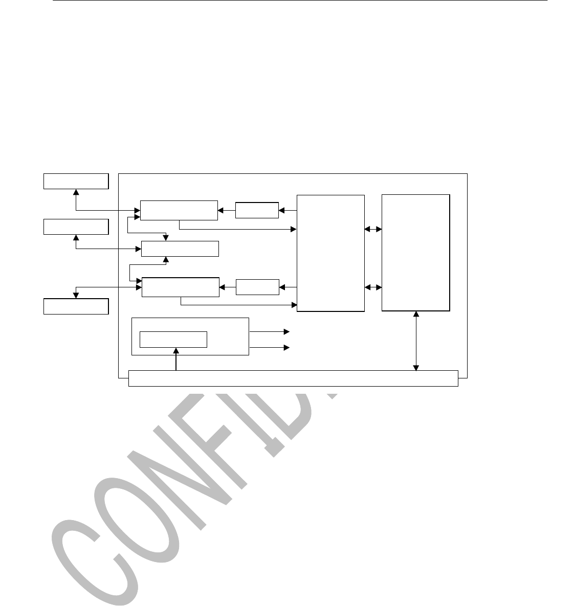
2. System block diagram
3. Product Spec
3-1. System Configration
3-2. Basic Spec
4. Outline Dimension
5. Manufacturing Test
5-1. Instruction
5-2. Test Configration
5-3. Test Flow and Criteria
6. Assembly and Label information
6-1. Instruction
6-2. Assembly drawing
6-3. Label Drawing
7. Packaging and Shipment
7-1. Instruction
7-2. Packing drawing
7-3. Shipment method
8. Restrictions about production
8-1. Manufacturers of aluminum electrolytic capacitor which BUFFALO approves
8-2. Manufacturers where BUFFALO prohibited use
9. Federal Communication Commission Interference Statement

PDBU-31119-X000-A0 3/8
BUFFALO INC.
1. Introduction
This document describes the design specifications of 802.11n Wireless miniPCI.
This product guarantees compatibility with IEEE 802.11n draft compliant goods.
And this product is compatible with IEEE802.11b/g legacy goods.
2. System block diagram
Power Supply
Dipole Antenna
Antenna Switch TX PA
Antenna Switch
PCI Bus
Regulator PCI bus
+3.3V
+2.5V
+1.8V
WZR-G300N BLOCK DIAGRAM
Dipole Antenna
Dipole Antenna
Antenna Switch
TX PA
MAC, B/B
(4321)
Transceiver
(2055)

PDBU-31119-X000-A0 4/8
BUFFALO INC.
3. Product Spec
3-1. System Configration
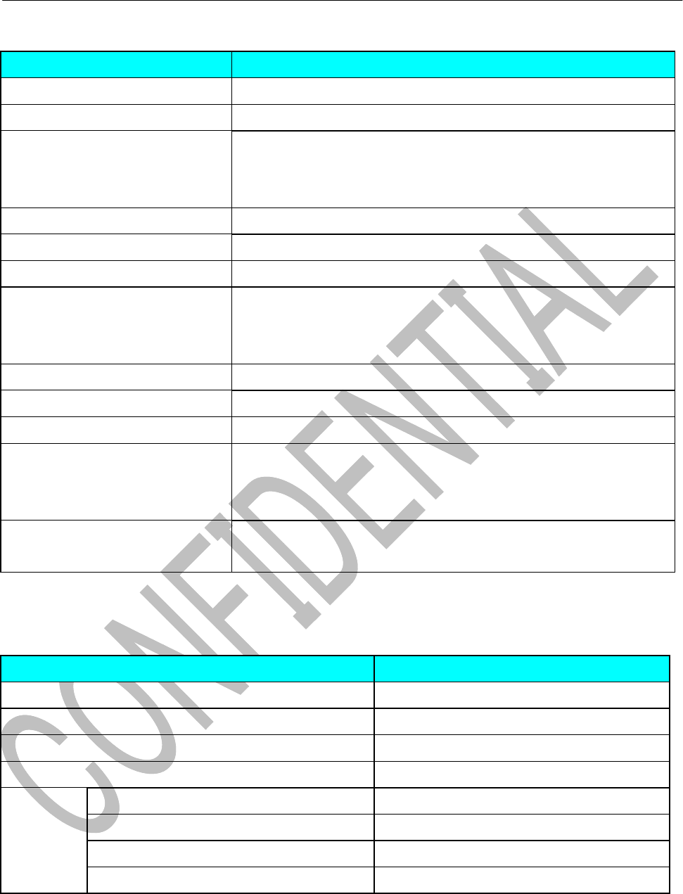
ITEM Contents
Interface / System bus support PCI
Standard IEEE 802.11g、802.11b
Data rete (Mbps) 54,48,36,24,18,12,9,6,11,5.5,2,1
20MHz BW: 130,117,104,78,52,39,26,13
40MHz BW: 270,243,216,162,108,81,54,27
Modulation PSK/CCK,DQPSK,DBPSK,OFDM
Network architectures Infrastructure and ad hoc
Operating channels 2.4GHz: 11 for North America, 13 for Europe, and 14 for Japan
RF Output Power 2x2: 2.4GHz 11n 15 dBm
2x2: 2.4GHz 11g 18 dBm
2x2: 2.4GHz 11b 17 dBm
Antenna connectors U.FL-R-SMT-1(10) HIROSE or compatibility connector
Power requirements DC 3.3V
Power consumption Average standby < 20mW
Security IEEE 802.1x, WEP/WEP2, WPA/WPA2, TKIP
, Weak-key avoidance, CCX, CCX2.0, CCX3.0
, 128bit OCB mode AES, IEEE 802.11i
Certifications IEEE 802.11-compliant, Wi-Fi CERTIFIED
, ACPI power management
3-2. Basic Spec
Basic Spec Contents
Garver version WMIB-200GN_V02
Schematic version WMIB-200GN_V02S
BOM version 970-300-0035R
Weight 25g
Reglation Japan MIC(Telec) ○ (apply by Buffalo)
FCC ClassB ○
CE ○
Wifi ○ (apply by Buffalo)

PDBU-31119-X000-A0 5/8
BUFFALO INC.
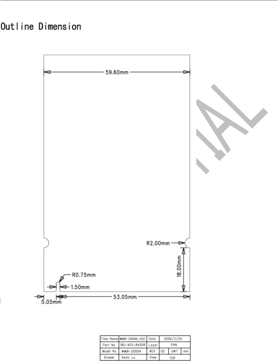
4. Outline Dimension

PDBU-31119-X000-A0 6/8
BUFFALO INC.
5. Manufacturing Test
The production company must report test result of wireless to BUFFALO in production test.
It must show that a produced product satisfies TELEC standard.
5-1. Instruction
5-2. Test Configration
5-3. Test Flow and Criteria
6. Assembly and Label information
6-1. Instruction
6-2.Assembly drawing
6-3.Label Drawing
7. Packaging and Shipment
7-1. Instruction
7-2. Packing drawing
7-3. Shipment method
8. Restrictions about production
8-1. Manufacturers of aluminum electrolytic capacitor which BUFFALO approves
Choose aluminum electrolytic capacitor among the following manufacturers.
凱美電機(JAMICON)
智寶(TEAPO)
世昕(LUXON)
TAICON
輝城(L-tec)
8-2. Manufacturers where BUFFALO prohibited use
The aluminum electrolytic capacitor must not use the following manufacturers.
Gloria
LELON(立隆)
Fuhjyyu
The ceramic condenser must not use the following manufacturers.
PanOverSea
TeamYoung(天揚)
The PCB must not use the following manufacturers.
TOPSEARCH

PDBU-31119-X000-A0 7/8
BUFFALO INC.
9. Federal Communication Commission Interference Statement
This equipment has been tested and found to comply with the limits for a Class B digital device,
pursuant to Part 15 of the FCC Rules. These limits are designed to provide reasonable protection
against harmful interference in a residential installation. This equipment generates, uses and can
radiate radio frequency energy and, if not installed and used in accordance with the instructions, may
cause harmful interference to radio communications. However, there is no guarantee that interference
will not occur in a particular installation. If this equipment does cause harmful interference to radio or
television reception, which can be determined by turning the equipment off and on, the user is
encouraged to try to correct the interference by one of the following measures:
- Reorient or relocate the receiving antenna.
- Increase the separation between the equipment and receiver.
- Connect the equipment into an outlet on a circuit different from that
to which the receiver is connected.
- Consult the dealer or an experienced radio/TV technician for help.
This device complies with Part 15 of the FCC Rules. Operation is subject to the following two
conditions: (1) This device may not cause harmful interference, and (2) this device must accept any
interference received, including interference that may cause undesired operation.
FCC Caution: Any changes or modifications not expressly approved by the party responsible for
compliance could void the user's authority to operate this equipment.
IMPORTANT NOTE:
FCC Radiation Exposure Statement:
This equipment complies with FCC radiation exposure limits set forth for an uncontrolled
environment. This equipment should be installed and operated with minimum distance 20cm
between the radiator & your body.
This transmitter must not be co-located or operating in conjunction with any other antenna or
transmitter.
Buffalo declares that WZR-G300N (FCC ID: FDI-09101466-0) is limited in CH1~CH11 for 2.4
GHz by specified firmware controlled in U.S.A.

PDBU-31119-X000-A0 8/8
BUFFALO INC.
This device is intended only for OEM integrators under the following conditions:
1) The antenna must be installed such that 20 cm is maintained between the antenna and
users, and
2) The transmitter module may not be co-located with any other transmitter or antenna.
As long as 2 conditions above are met, further transmitter test will not be required. However, the
OEM integrator is still responsible for testing their end-product for any additional compliance
requirements required with this module installed (for example, digital device emissions, PC
peripheral requirements, etc.).
IMPORTANT NOTE: In the event that these conditions can not be met (for example certain laptop
configurations or co-location with another transmitter), then the FCC authorization is no longer
considered valid and the FCC ID can not be used on the final product. In these circumstances, the
OEM integrator will be responsible for re-evaluating the end product (including the transmitter) and
obtaining a separate FCC authorization.
End Product Labeling
This transmitter module is authorized only for use in device where the antenna may be installed
such that 20 cm may be maintained between the antenna and users (for example: Access point,
Router…etc). The final end product must be labeled in a visible area with the following: “Contains
TX FCC ID: FDI-09101466-0”.
Manual Information That Must be Included
The OEM integrator has to be aware not to provide information to the end user regarding how to
install or remove this RF module in the users manual of the end product which integrate this
module.
The users manual for OEM integrators must include the following information in a prominent
location “ IMPORTANT NOTE: To comply with FCC RF exposure compliance requirements, the
antenna used for this transmitter must be installed to provide a separation distance of at least 20
cm from all persons and must not be co-located or operating in conjunction with any other antenna
or transmitter.