BUFFALO 09101556-0 Wireless-N High Power ADSL2+Modem Router User Manual Manual
BUFFALO INC. Wireless-N High Power ADSL2+Modem Router Manual
BUFFALO >
Manual
www.bualotech.com
WBMR-HP-GN
Wireless-N
High Power ADSL2+ Modem Router
User Manual

Table of Contents
1 Introduction 1
2 Understanding your Router 4
3 Installing your Router 7
4 Accessing the User Interface 10
5 Understanding the Web-Based User Interface 11
6 Understanding the Web-Based User Interface 15
7 Internet/LAN 15
8 Wireless Cong 19
9 Security 27
10 Gaming Ports 28
11 Admin Cong 30
12 Diagnostic 33
13 EU - Declaration of Conformity 35

1
Introduction 1
Thank you for your purchase of the Bualo Wireless- N ADSL2+ High Power
Modem Router. In minutes you will be able to share your Internet connection
and network your computers with your new Router.
Package Contents
• Wireless-NNnitiADSL2+ModemRouter(WBMR-G300N)
• UtilityCD-ROMw/UserManual
• QuickSetupGuide
• ACAdapter
• EthernetCable
• DSLCable
• WarrantyStatement
System Requirements
•ActivatedBroadbandADSLLine
•PCwithaClientAdapter
•Microsoft®WindowsXP/Vista™(SetupWizardsupported)
•MacintoshOSorotherOperatingSystemwithTCP/IPProtocolInstalled
(SetupWizardnotsupported)
•InternetExplorer5.0orhigher
•NetscapeNavigator4.7orhigherforWeb-basedConguration
•CD-ROMDrive
Gathering Information
MostDSLprovidersrequirePPPoEorPPPoAdetailstologintoyour
connection. You must call your ISP’s Technical Support number to obtain the
following information:
Username:ThisistheUsernamethatisusedtologontoyourADSLservice
provider’snetwork.Itiscommonlyintheform−user@isp.com.
Password: This is the Password that is used, in conjunction with the Username
above,tologontoyourADSLserviceprovider’snetwork.
ConnectionProtocol:ThisisthemethodthatyourADSLserviceprovideruses
tosendandreceivedatabetweentheInternetandyourcomputer.
VPI:ThisistheVirtualPathIdentier(VPI).Itisusedinconjunctionwiththe

2
VirtualChannelIdentier(VCI)below,toidentifythedatapathbetweenyour
ADSLserviceprovider’snetworkandyourcomputer.
VCI:ThisistheVirtualChannelIdentier(VCI).Itisusedinconjunctionwith
theVPIabovetoidentifythedatapathbetweenyourADSLserviceprovider’s
network and your computer.
Note: This information should be stored and kept to hand as it will be
requiredtoenableyoutoestablishaninternetconnection.
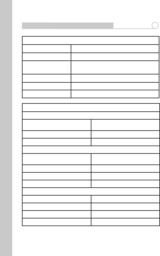
ThetablebelowisaquickreferenceguideforconguringyourADSLInternet
connection. You may try the settings for the ISPs shown.
Country Encapsulation VPI/VCI Multi-
plexing ISPs
France PPPoE 12997 LLC Various
Germany PPPoE 11689 LLC T-Online,Various
Holland
1483 Bridged
0/35
0/32
0/34
LLC-
BBNed,XS4allVer-
satel, DHCP Baby
XL,Tiscali.(start/
Surf/Family/Live)
PPPoA 8/48 VCMUX
KPN, Hetnet,
HCCNet, Tiscali
(lite/Basis/Plus),
Wanadoo
PPPoA 0/32 VCMUX VersatelPPP,
Zonnet
PPPoE 8/35 LLC Various
Belgium PPPoA 8/35 LLC Belgacom, Tiscali,
Scarlet
Ireland PPPoE 8/35 LLC
Eircom, BT,
Digiweb, Irish
Broadband
Italy PPPoE 8/35 VCMUX TIN
Spain PPPoE 8/32 LLC Telefonica

3
Sweden 1483 Bridged 3/35 LLC Telia
UK PPPoA 0/38 VCMUX BT,Freeserve,
Tiscali,AOL
4
Understanding Your Router 2
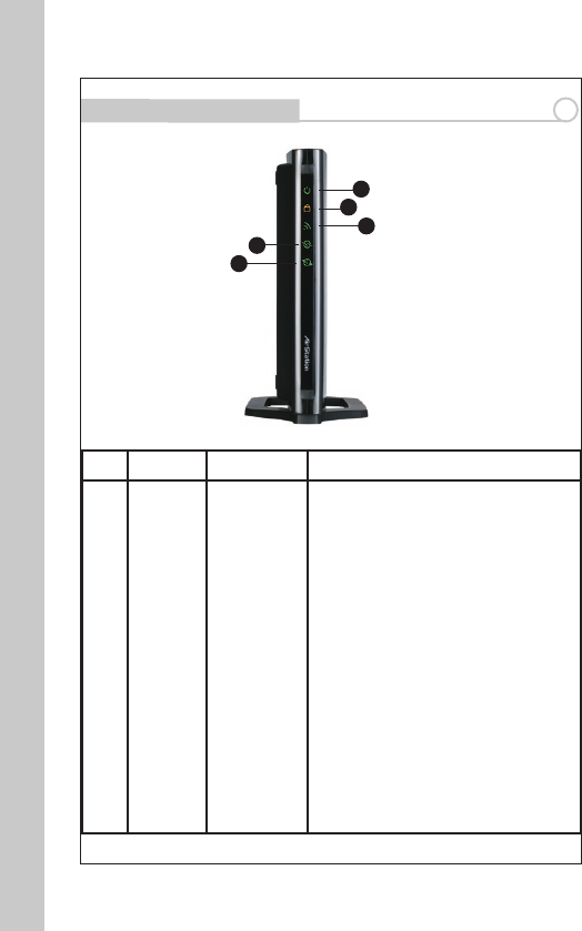
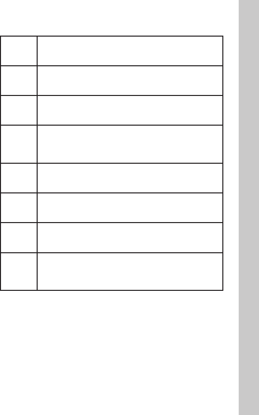
Front Panel
No Name Colour Description
1POWER Green or Red
ON(Green):PowerOn
OFF:PowerO
Continuousashing(Red):Writingto
Flash-ROM(e.g.changingsettings,updat-
ingrmware)
Flashonce(Red):RAMerror(e.g.access,
recognizedstoragesize)
Flashestwice(Red):Flash-ROMerror(e.g.
access,parametersettings)
Flashesthreetimes(Red):Wireddevice
error(Example:wireddriverinstallerror)
Flashesfourtimes(Red):Wirelessdevice
error,Wireddeviceerror(e.g.Wireless
Driverinstallerror)
Flashesvetimes(Red):Networkerror
(e.g.IPaddressatWANsideiswithinLAN
network)
Flashesninetimes(Red):Systemerror
(e.g.thedevicehasstoppedworking)
1
2
3
4
5

5
2 SECURITY Orange
ON:WirelessSecurityenabled
OFF:WirelessSecuritydisabled
Flashestwice:WaitingforAOSS/WPS
(PBC)tobeactivated.
Flashescontinuously:AOSS/WPS(PBC)
setup has failed due to timeout/negotia-
tionerror–(LEDwillturnoafter30mins,
ifsecurityisnotset.)
3 WIRELESS Green
ON:Wirelessconnectionavailable
OFF:Wirelessconnectionisinactive/not
available
Flashing: Communicating wirelessl
4 DSL Green
ON:DSLissynchronizing
OFF:Modemfunctioniso
Series of 2 ashes: Searching for carrier
signal
Series of 4 ashes: Carrier signal found
and connecting modem.
5 INTERNET Green or Red
ON:DSLissynchronizing
OFF:Modemfunctioniso
Series of 2 ashes: Searching for carrier
signal
Series of 4 ashes: Carrier signal found
and connecting modem.
TheSecuritybuttonislocatedonthetopofthedeviceasshownbelow:
6
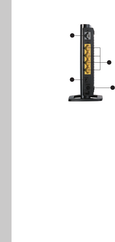
Back Panel
1. DSL Line
Connect your ADSL line to this port.
2. LAN Ports
The Ethernet ports are RJ45, 10/100 auto-negotiation. The ports are labelled 1
through 4. These ports correspond to the numbered LEDs on the front of the
Router.Connectyournetwork-enabledcomputersoranynetworkingdevices
to one of these ports.
3. Security Selection Switch
Thisswitchallowsyoutochoosetherequiredmethodtocongureawireless
connection,eitherWPSorAOSS.ToinitiateAOSS,youmustalsopressthe
AOSSbuttononthetopofthedevice.
4. Power
Connect the included power cord to this inlet.
The “Reset” button is located on the bottom of the modem router and should
be used in rare cases when the Router may function improperly. Resetting
the Router will restore the Router’s normal operation while maintaining the
programmed settings.
You can also restore the factory default settings by using the Reset button.
Usetherestoreoptionininstanceswhereyoumayhaveforgottenyour
custom password.
1
2
3
4

7
a. Resetting the Router - Push and hold the Reset button for one second then
release it. When the Power LED becomes solid again, the reset is complete.
b. Restoring to Factory Defaults - Press and hold the Reset button for 10
seconds then release it. When the Power LED becomes solid again, the restore
is complete.
Router Label
The label on the back of the modem router shows the router’s MAC address
(SSID),serialnumber,securityPIN,andfactorydefaultlogininformation.
Positioning your Router
Your wireless connection will be stronger the closer your computer is to your
Router.Typicalindooroperatingrangeforyourwirelessdevicesisbetween
30m and 60m. In the same way, your wireless connection and performance
will degrade somewhat as the distance between your Router and connected
devicesincreases.Thismayormaynotbenoticeabletoyou.Asyoumove
farther from your Router, connection speed may decrease. Factors that can
weakensignalssimplybygettinginthewayofyournetwork’sradiowaves
aremetalappliances,orobstructions,andwalls.Ifyouhaveconcernsabout
your network’s performance that might be related to range or obstruction
factors,trymovingthecomputertoapositionbetween1.5mand3.0mfrom
the Router, in order to see if distance is the problem.
Installng Your Router 3
Smart Wizard Installation
TohelpsetupyourrouterandconnecttotheInternetquickly,theresource
CDcontainsaSmartWizard.ThewizardontheAirNavigatorCDwillassist
inconnectingyourequipment,conguringwirelesssettingsandenabling
security.InserttheCD,launchthewizardandfollowthestepsasindicated.
YouwillneedtheADSLsettingsinformationasprovidedbyyourISP.
Alternatively,tosetuptheconnectionmanually,proceedtothenextsection.
Note:IfyouhaveaMacintoshorLinuxsystem,youwillneedtousethe
manual installation method.

8
Manual Installation
1.Poweroyourcomputersandnetworkingequipment.
2.ConnectyourcomputertooneoftheYELLOWRJ45portsontherearofthe
Router with the supplied Ethernet network cable.
3. Connect your ADSL Line
ConnectionfortheRoutertotheADSLlinevariesbycountryandregion.
Typicallyitinvolvesamicrolteroramicrolterwithbuilt-insplitterto
allowsimultaneoususeofADSLserviceandtelephoneserviceonthesame
telephone line. Please read the following steps carefully and select the
appropriate method.
•IfyourtelephoneserviceandADSLserviceareonthesametelephone
line,ADSLmicroltersareneededforeachtelephoneanddevice,suchas
answeringmachine,faxmachine,andcallerIDdisplay.Additionalsplitters
may be used to separate telephone lines for telephone and Router. Note: Do
not connect the ADSL microlter between the wall jack and the Router—this
willpreventADSLservicefromreachingthemodem.
•IfyourtelephoneserviceandADSLserviceareonthesametelephone
line and you are using an ADSL microlter with built-in splitter, connect the
splittertothetelephonewalljackprovidingADSLservice.Then,connectthe
telephone cord from the ADSL microlter RJ11 port generally labelled “DSL”
to the gray RJ11 port labelled “DSL line” on the back of your Router. Connect
thetelephonydevicetotheotherportontheADSLsplittercommonly
labelled “Phone”.
•Note:AnRJ11telephonecordissupplied.WheninsertinganRJ11plug,be
sure the tab on the plug clicks into position correctly.
•IfyouhaveadedicatedADSLservicetelephonelinewithanRJ11walljack,
simply connect a telephone cord from the wall jack to the DSL port on the
back of your Router.
•IfyouhaveanRJ45walljackforyourADSLservice,connectanRJ45-to-RJ11
convertertothewalljack.Thenconnectoneendofthetelephonecordtothe
converterandtheotherendtotheDSLportonthebackofyourRouter.
4. Powering Up your Router
•ConnectthesuppliedpowercordtotheRouterpower-input.

9
•Afterconnectingthepowercordandthepowersourceisturnedon,the
Router’s power icon on the front panel should be on. It might take a few
minutes for the Router to fully start up.
•Turnonyourcomputer.Afteryourcomputerbootsup,theLANstatusLED
on the front of the Router will be on for each port to which a wired computer
isconnected.Theselightsshowyoutheconnectionandactivitystatus.Now
you are ready to congure the Router for ADSL connection.
In order for your computer to properly communicate with your Router, you
willneedtochangeyourcomputer’s“TCP/IPEthernet”settingsto“Obtain
an IP address automatically/Using DHCP”. This is normally the default setting
in most home computers. Consult your operating system’s Help les for
informationonchangingthissetting,ifrequired.
10
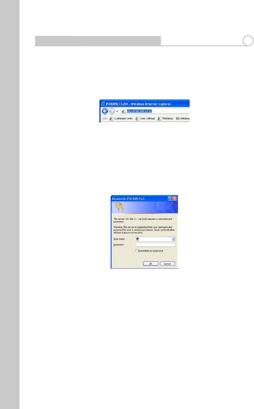
Accessing the User Interface 4
1. You can access the web-based management user interface of the Router
using the Internet browser on a computer connected to the Router. Type
“http://192.168.11.1” in your browser’s address bar. Then press the “Enter” key.
Note: It is strongly recommended that you use a computer physically
connected to the Router with an RJ45 cable for initial setup. Using a wirelessly
connected computer for initial setup is not recommended.
2. The following screen will appear in your browser to prompt you to log in.
The default User Name is “Root” and the default Password is blank. Click on
the“OK”buttontologin.
Note: It is strongly recommended that you set a password for increased
security.
11
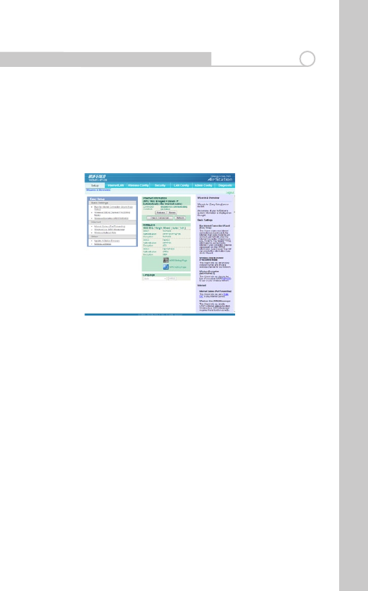
Understanding the Web-Based User Interface 5
Quick-NavigationTabs-YoucangodirectlytoanyoftheRouter’sUIpages
byclickingdirectlyontheselinks.Thelinksaredividedintologicalcategories
and grouped by tabs to make nding a particular setting easier to nd.
Helpisavailabletotherightofeachpage.
SETUP
Thepaneltotheleftofthispagecontainssetupwizardstoallowyouto
quicklyandconvenientlymakechangestoyourmodemrouterconguration.
Wizardsareprovidedforthefollowingfeatures:
•InternetConnection-ThisWizardscansyourInternetconnectionand
connects to the Internet. Most cable modems will connect automatically
whentheInternetConnectionWizardisrun.DSLmodemsmayrequire
PPPoEinformationtoconnecttotheInternet.Ifyourconnectionrequiresa
passwordorotherPPPoEinformation,haveitready!YourISPcanprovidethis
informationifyoudon’thaveit.
•WirelessSSID-ThisWizardletsyousetanSSID(networkname)andchosea
wireless channel for your network.
•WirelessEncryption-ThisWizardletsyouchoosethetypeofencryptionto
use on your wireless network.
•Portforwarding-ThisWizardletsyousetaStaticNATtoplayInternet
Games.
•WindowsLiveMessengerSettings-ThisWizardletsyouenableUPnP’s
Internetgatewayfunction.WindowsLive(MSN)Messengerrequiresthisto
12
function correctly.
•WirelessMulticastRate-ThisWizardsetstheWirelessMulticastRateand
IPv6PassThrough.
•FirmwareUpdate–ThiswizardinstallsanAirStationFirmwareupdate.
•Initialisation-ThisWizardrestorestheAirStationtofactorydefaultsettings.
AnoverviewofyourAirStation’ssysteminformationisdisplayedontheright.
The wireless section displays the status and encryption settings of your
wireless LAN access point.
ShortcutsarealsoavailableforAOSSandWPSconnectionmethods.
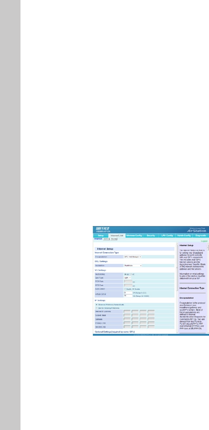
INTERNET/LAN
Internet
The Internet Setup section is for setting your broadband gateway to work
correctlywithyourISP’sequipment.ThisincludesyourISP’sInternetservers
andtheAsynchronousTransferMode(ATM)networkbetweenthegateway
andtheservers.
Note: Information on what settings to use in this section must be obtained
from your ISP.
The “Internet/LAN” tab is where you will set up your Router to connect to your
InternetServiceProvider.

13
Connection Type
Fromthe“ConnectionType”dropdownbox,youcanselectoneoftheseve
connectiontypesbasedontheinstructionprovidedbyyourISP:
•RFC2516PPPoE
•RFC2364PPPoA
•1483Bridged
•1483Routed
•BridgeModeOnly
Setting your ISP Connection Type to PPPoE or PPPoA
PPPoE(Point-to-PointProtocoloverEthernet)isthestandardmethodofcon-
nectingnetworkeddevices.Itrequiresausernameandpasswordtoaccess
thenetworkofyourISPforconnectingtotheInternet.PPPoA(PPPoverATM)
is similar to PPPoE, but is mostly implemented in the UK.
Setting your Connection Type to RFC 1483 Bridged/Routed
This connection method bridges your network and your ISP’s network
together. The Router will obtain an IP address automatically from your ISP’s
DHCPserver.
SettingyourConnectionTypetoBridgeModeOnly(DisableInternetSharing)
In this mode, the Router simply acts as a bridge passing packets across the
DSLport.Itrequiresadditionalsoftwaretobeinstalledonyourcomputersin
order to access the Internet.
14
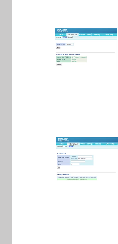
DDNS
If your Modem Router’s Internet IP address is assigned dynamically and
youwishtohostaWebsiteorotherInternetservice,youcansignupwith
DynDNS.orgorTZO.comforDynamicDNS(DDNS)service.
SelectyourDDNSproviderfromthislistbox,entertherequiredinformation,
andclickApply.ThegatewaywillsenditsInternetIPaddresstotheprovider
sotheprovidercanupdateyourDNSentry.
ForDDNS.orgservice,youmustenterausername,password,andhostname.
ForTZO.comservice,youmustllinthecorrecte-mailaddress,password,
and domain name
Route
NetworkAddressTranslation(NAT)letsyouuse“private”(andcost-free)IP
addressesonyourLANandasingle“public”IPaddress(whichyoumust
payfor)ontheInternet.WhenalocalcomputeraccessestheInternet,your
broadband modem router changes the source address from the computer’s
to its own Internet IP address. When a response comes back, it changes the
destinationaddressfromitsInternetIPaddresstotherequestingcomputer’s

15
localIPaddress.NATisenabled(turnedon)bydefault.Disableitifyoudonot
need it.
WIRELESSCONFIG
ForinformationonconguringaconnectionwithWPSorAOSS,pleaserefer
to the earlier sections of the manual which describe how to use these meth-
ods to establish a wireless connection.
Basic
The “Basic” tab lets you make changes to the wireless network settings - wire-
lessnetworkname(SSID),radio,operatingchannelandsecuritylevel.
Wireless Radio
Select Disable to turn o wireless networking, or select the type of wireless
networkyouaresettingup:Mixed(with11b,11gandDraft11nclients),
BG-Mixed(withonly11band11gclients),orsolely11b,11gorDraft11n
clients. Using the correct setting here ensures that the network will work as
eciently as possible.
Wireless Channel
Your Router is congured to operate on the proper channels for the country
you reside in. If there are other wireless networks operating in your area,
your network should be set to operate on a channel that is dierent than the
other wireless networks. For best performance, use a channel that is at least
vechannelsawayfromtheotherwirelessnetworks.Forinstance,ifanother
network is operating on channel 11, then set your network to channel 6 or
below.

16
300MHz Mode
Band Width
Youcanselectwhethertouse20MHzor40MHzmodesforwirelesscom-
munication.
The20-MHzchannelbandwidthlessensthechanceofinterferencewithother
wireless networks.
However,thewide40-MHzchannelbandwidthincreasesthroughputupto
300Mbps.
Thedefaultsettingis20MHz.
Extension Channel
When40MHzhasbeenselectedunderBandWidth,twochannelsareused-a
ControlChannelandanExtensionChannel.
The Control Channel is specied by the [Wireless Channel] setting , and the
ExtensionChannelisspeciedbythe[ExtensionChannel]setting.
Broadcast SSID
For security purposes, you can choose not to broadcast your network’s SSID
(setto“Allow”bydefault).Doingsowillkeepyournetworknamehiddenfrom
computers that are scanning for the presence of wireless networks. To turn o
thebroadcastoftheSSID,removethetick.
Security/Encryption
The WBMR-HP-GN modem router includes a security feature which allows
eachwirelessclienttoconnectwithadierentlevelofsecurity.Thisfunction
is particularly useful in a situation where a single client can only connect
viaWEP(lowestlevelofsecurity).Becauseclientscanconnectatdierent
encryptionlevels,itmeansthatthesecurityoftheremainingwirelessdevices
is not compromised.
Toidentifyyourwirelessnetwork,anamecalledtheSSID(ServiceSet
Identi¬er)isused.ThedefaultSSIDoftheRouterisprintedonthelabel
attached on the back of the Router . You can change this to anything you
wanttooryoucanleaveitunchanged.TochangetheSSID,typeintheSSID
that you want to use in the SSID eld. If you make a change to the SSID, your
wireless-equippedcomputersmayalsoneedtobereconguredtoconnect
to your new network name.
You can also change the Pre-Shared Key or password for each encryption
typeandtheRekeyinterval(frequencywiththekeywillberenewed).

17
SSID1
WirelessencryptionWPA-PSK-TKIPorWPA/WPA2-MixedisusedforMulti
Security SSID1.
SSID2
Wireless encryption WPA-PSK-AES is used for Multi Security SSID2.
SSID3
Wireless encryption WEP is used for Multi Security SSID3.
Advanced Wireless Settings
BSS BasicRateSet
BSS(BasicServiceSet)conguresthetransmissionrateofcommunicationfor
wirelessclients.Setupchoicesmayvarywithdierentwirelessclients.
Multicast Rate
You can select 1, 2, 5.5, 6, 9, 11, 12, 18, 24, 36, 48, 54Mbps or Auto.
DefaultValueis“Auto”.
Reverse Direction Grant
ChoosewhetherReverseDirectionGrant(RDG)functionisenabledor
disabled.
DuringanRDexchangesequence,theRDinitiatorstationmaytransmitPP-
DUsandobtainresponsePPDUsfromasinglestation(RDresponder)during
theexchange.
WirelessLANdevicesthatconnecttotheAirStationmustalsoenabletheRDG
function.
DTIM Period
DTIM(“DeliveryTracIdenticationMaps”)Periodisanintervalwhenwire-
lessLANequipmentbroadcastsDTIMinformation.Settinglargervaluessaves
18
power but may slow network trac. This setting is ignored unless power
managementisactivatedonthewirelessclient.Valuesthatcanbeinputted:
1-255.Defaultvalueis“1”.
Privacy Separator
ChoosewhetherPrivacySeparatorfunctionisenabledordisabled.
WhenPrivacySeparatorisenabled,eachwirelessLANdeviceconnectingto
theAirStationcannotcommunicatewithotherlocalwirelessdevices.
However,communicationwithwiredLANorInternetsidedevicesisstill
available.
Output Power
OutputPowerandtherangeoftheassociatedelectromagneticwavesare
almostproportional.IftheOutputPoweriscutto50%,theAirStation’srange
will be shortened by about half. You may limit your AirStation’s range by
modifyingthisvalue.Defaultvalueis“100%”.
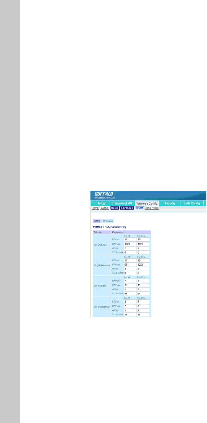
WMM
WMM(Wi-FiMultimedia)providesmultimediaenhancementsforWi-Fi®
networksthatimprovetheuserexperienceforaudio,video,andvoiceap-
plications.WMMPowerSaveincreasestheeciencyandexibilityofdata
transmission..
This screen allows you to prioritise AirStation communication for specic
transactions.Forexampleyoumaychangesettingswhichcanhelpimprove
thequalityofVOIPorotherstreamingprotocols.
19
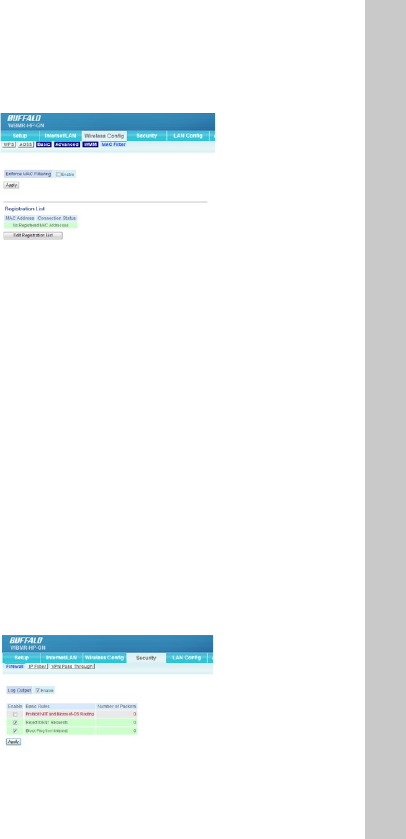
MAC Filter
The MAC Filter is a powerful security feature that allows you to specify which
computers are allowed on the network. Wireless connections to the AirStation
can be limited to specic client MAC addresses to enhance security against
unwantednetworkvisitors.Whenenabled,onlywirelessclientadapterswith
registered MAC addresses will be allowed to connect to the AirStation.
Note:ThewirelessMAClterisignoredwhileAOSSisinuse.
Check Enable to use MAC ltering.
Click the “Registration List” button to display the MAC Address Filter List. To
putadeviceonthelist,youmustknowitsMediumAccessControl(MAC)
address, often called its MAC or LAN MAC. This normally can be found on a
labelonthebottomorbackofthedevice,oronthenetworkinterfacecardin
a desktop computer.
WhenthedesiredMACaddressesareentered,click“Register”tosavethelist.
SECURITY
Firewall
20
Limits the type of packets allowed to pass between the Internet and LAN.
WhenpacketsreachtheAirStation,therewallevaluatesthepackets,and
forwards packets that don’t match any lter to their destination. The Firewall
blocksunnecessarypacketsfromtheInternetsideandpreventsleaking
secure information from the LAN side.
Prohibit NBT and Microsoft-DS routing
PreventsunexpectedexternalaccessviaMicrosoftnetworksharing.The
default setting is disabled.
RejectIDENTrequests
Whenthisisenabled,theAirStationsendsrejectpacketsifitreceivesan
IDENTrequest.Thedefaultisenabled.Usethislterwhenthecommunication
speed goes down using a network application like e-mail, ftp or WEB. If IDENT
requestsareforwardedtoaLANsideclientbyaddresstranslationsetting
(DMZorTCPport:113),thisbasicruleisignored.
Block Ping from Internet
An“anonymousInternetrequest”isanattemptto“ping”yourbroadband
gateway’s WAN interface. Pinging is a way of checking if a system is running
at a particular IP address. It can also be used to hunt for certain kinds of
vulnerabilitiesinthesystem.BlockingWANrequestsmeansnotresponding
to pings coming from the Internet. This is the default setting.
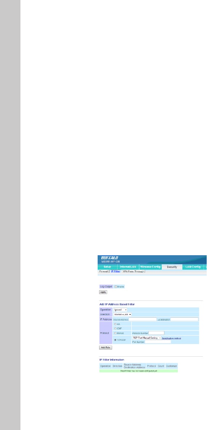
IP Filter Settings
21
Limits the type of packets allowed to pass between the Internet and LAN. The
maximumnumberofrulesis32.
If the packet meets one of the monitoring conditions before it is routed, the
specied action will be taken. If multiple conditions are met, the appropriate
action will be performed once the packet meets the condition.
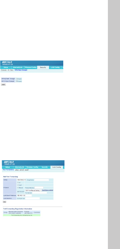
VPN Pass Through
PPPoE Pass Through
This setting enables an rfc1483 bridge mode in the modem so the PPPoE
processoccursintheconnecteddevice,egarewallrouterorPC.
PPTP Pass Through
PPTP is a tunneling protocol dened by the PPTP forum that allows PPP pack-
etstobeencapsulatedwithinInternetProtocol(IP)packetsandforwarded
overanyIPnetwork,includingtheInternetitself.PPTPensuresthatmessages
aretransmittedfromoneprivatenetworktoanother.
LANCONFIG
Port Forwarding
22
PortForwardingallowsyoutorouteexternal(Internet)callsforservicessuch
asawebserver(port80),FTPserver(Port21),orotherapplications,through
your Router to your internal network. Since your internal computers are pro-
tected by a rewall, machines from the Internet cannot get to them because
they cannot be “seen”. If you need to congure the port forwarding function
foraspecicapplication,youwillneedtocontacttheapplicationvendor
to nd out which port settings you need. You can manually input this port
information into the Router.
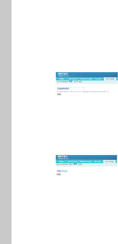
DMZ
IfyouhaveaclientPCthatcannotrunanInternetapplicationproperlyfrom
behind the rewall, you can open the client up to unrestricted two-way Inter-
net access. This may be necessary if the NAT feature is causing problems with
anapplicationsuchasagameorvideoconferencingapplication.Usethis
featureonatemporarybasisasaDMZhostishighlyexposedtothedangers
of the Internet
To put a computer in the DMZ, enter its LAN IP address and click “Apply” for
the change to take eect.
UPnP
SettinguptheinternetgatewayfunctionofUPnP:OnaPCwhichsupports
UPnP(WindowsXP,etc.),theAirStationisautomaticallyrecognizedonthe
LAN as an internet gateway. Also, if a network application which supports
UPnPisused,itcanacquiretheInternetportstatusoftheAirStationand
the Internet IP address obtained from your ISP, and perform port translation
automatically.

23
QoS
QualityofService(QoS)assignsprioritylevelstodierentkindsofpackets
tominimizedelaysinthetransferofdata.Thetablelistsfourcommonap-
plications and lets you enter the port numbers for up to four more. Click the
HighPrioritybuttonfortheapplication(s)whosepacketsyouwishtoreceive
preferential treatment.
ADMINCONFIG
Name
ThiscanbeusedtoassignaspecicdescriptivenamefortheAirStation.
The AirStation name may be up to 64 alphanumeric characters in length, and
’-’ are allowed, but a ’-’ may not be the rst or last character in the name. By
default, the AirStation name is its LAN-side MAC address. This name is used
asthehostnamefortheInternetsideDHCPserverwhentheDHCPclientis
enabled.
Whenloginformationtothesyslogserveristransmitted,itusesitasthehost
name.
Password
ConguretheAdministratorPasswordtoreviewtheAirStationsettings.
Change your root password here. Password may use alphanumeric characters
and underscores [_], and may be up to 8 characters long.
The default username is the word root and this setting cannot be changed.
Time/Date
YoumaysettheAirStation’sdateandtimemanuallyoracquirethisinforma-
tionfromyourPC(TheTimeZonecannotbeacquiredbythismethod)
NTP
IfanNTPserveriscongured,theAirStationwillaccessthespeciedNTP
serverandadjustit’sinternalclocktoconformwiththeNTPserver’stime.NTP

24
isanacronymofNetworkTimeProtocol.AnNTPserverdistributesaccurate
timetonetworkdevices.
Access
You may prohibit management of the AirStation in specic circumstances.
Enablinganyoftheselimitationswillpreventchangesbeingmadetothe
AirStation’s settings from PCs that meet the listed limitation criteria. Note that
checkingalloftheseboxesatoncewillmakeitverydiculttomakefuture
changes to the AirStation’s settings.
Log
YoucantransfertheAirStation’sloginformationtoaserver.
Checking [Enable] will instruct the AirStation to transmit log information to a
Syslogserver.Thedefaultsettingisdisabled.
Save/Restore
Onceyou’vegotyourAirStationsetupthewayyouwantit,youmaysave
the current conguration to a le on the PC. This can then be used to restore
settingsasrequired.
Note:
TheAirStationwillnotbeabletorestorecongurationsfromthesavelein
the following circumstances:
•Ifyoupassword-protectthebackupandthendon’tenterthepassword
correctly when restoring.
•Congurationlecreatedwithalaterversionofthermwarethanyouare
currently running.
•Congurationlewascreatedbyadierentproduct.
Initialize/Restart
SometimesitmaybenecessarytorestartorinitializetheRouterifitisnot
workingcorrectly.RestartingtheRouterwillNOTdeleteanyofyourcongu-
ration settings.
However,ifyouchoosetoinitializeyourAirStationsettingswillberestoredto
factory defaults.
Update
Fromtimetotime,BualomayreleasenewversionsoftheRouter’srmware.
Firmwareupdatescontainfeatureimprovementsandxestoproblemsthat
mayhaveexisted.WhenBualoreleasesnewrmware,youcandownload
the rmware from the Bualo website and update your Router’s rmware to
thelatestversion.

25
Updating the Router’s Firmware
1. In the “Update” screen, click “Browse”. A window will open that allows you
to select the location of the rmware update le.
2. Browse to the rmware le you downloaded. Select the le by double-
clicking on the le name.
3.Click“UpdateFirmware”toupdatetothelatestrmwareversion.
DIAGNOSTIC
Diagnostic panels show the current status of your modem router, its local
network connection, the wireless interface, and the DSL link. The informa-
tion displayed is read-only ie. you cannot change any settings through these
panels.
System Info
Display the AirStation’s main settings.
Logs
Displays log information recorded by your AirStation. Select the type of
information you wish to log and the location.
Packet Info
DisplaysthetotalnumbersofpacketssentandreceivedbytheAirStation,
and any errors.
Client Monitor
DisplaystheLANsideclients(PC’s)thatareaccessingtheAirStation.
Ping
A Ping test can be performed from your AirStation. With a ping test, you can
establish whether the AirStation can communicate with a specic network
device.EnterthenetworkIPaddressthatyouwanttoping;e.g.192.168.11.3
orwww.bualotech.com.Click[Execute]andtheresultsofthetestare
displayed.
DSL Connection
If a DSL link has been established, technical information about it is shown
here.ThePVCConnectionsectionreectssettingsintheInternetConnection
andVCSettingsareasoftheInternet/LANpanel.
26
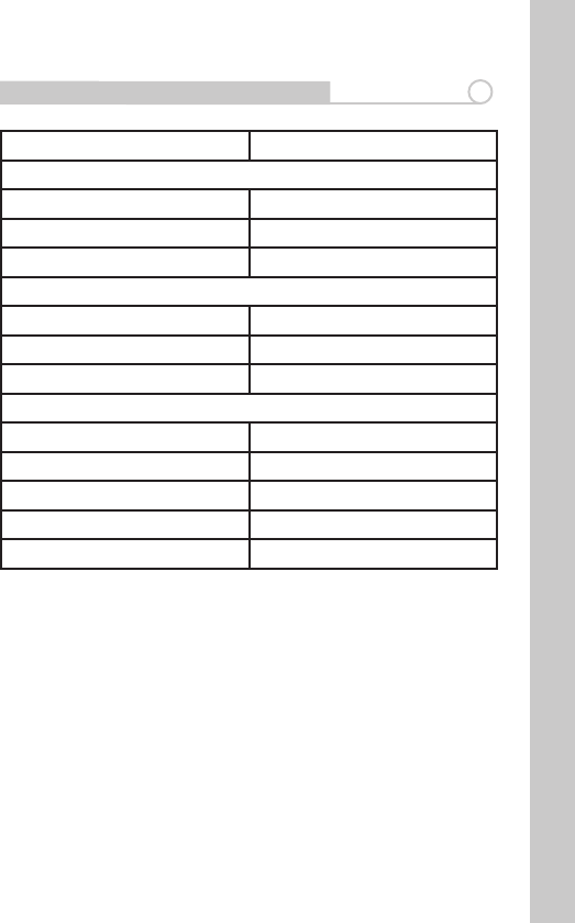
Technical Specications 6
Specications
Dimensions: (W)130x(H)143x(D)28mm
Weight: 210g
Operatingtemperature: Temperature 0-40°C,
Humidity20-80%(NonCondensing),
Power Consumption: 11W
Power Supply: 12V/2A
CDsetupwizard: Microsoft®WindowsXP/Vista™
Network Protocol and Standards Compatibility
DSL Interface
Standard TR067/TR068/G.922.1/G.992.2/G.992.3/
G.992.4/G.992.5/ T1.413
Connector Type RJ11
Number of DSL Ports 1
LAN Interface
Standard Compliance IEEE802.3IEEE802.3u(100BASE-
TX/10BASE-T)Auto-MDIX
Speed 100Mbps
Connector Type RJ45
Number of LAN Ports 4
WAN Interface
Standard Compliance Draft2.0 802.11n/802.11b/g
Frequencyrange 1-11ch2412-2462MHz)
Antenna Internal 2dBi 1pcs
Wireless Security WPA/WPA2
27
Default Factory Settings 7
Feature Default Setting
Router Login
User Login URL http://192.168.11.1
UserName(casesensitive) root
Login Password ““(blank)
Internet Connection
WAN MAC Address Use Default address
WANMTUSize 1500
Port Speed AutoSensing
LocalNetwork(LAN)
Lan IP 192.168.11.64
Subnet Mask 255.255.255.0
DHCPServer Enabled
DMZ Disabled
Time Zone GMT

28
Regulatory Compliance Information 7
Europe – EU Declaration of Conformity
ThisdevicecomplieswiththeessentialrequirementsoftheR&TTEDirective
1999/5/EC.Thefollowingtestmethodshavebeenappliedinordertoprove
presumptionofconformitywiththeDirective:
EN60950-1: (2006)
SafetyofInformationTechnologyEquipment
EN50385 : (2002-08)
Product standard to demonstrate the compliance of radio base stations and
xedterminalstationsforwirelesstelecommunicationsystemswiththe
basicrestrictionsorthereferencelevelsrelatedtohumanexposuretoradio
frequencyelectromagneticelds(110MHz-40GHz)-Generalpublic
EN 300 328 V1.7.1: (2006-10)
ElectromagneticcompatibilityandRadiospectrumMatters(ERM);Wideband
Transmissionsystems;Datatransmissionequipmentoperatinginthe2,4GHz
ISMbandandusingspreadspectrummodulationtechniques;Harmonized
ENcoveringessentialrequirementsunderarticle3.2oftheR&TTEDirective
EN 301 489-1 V1.8.1: (2008-04)
ElectromagneticcompatibilityandRadioSpectrumMatters(ERM);Electro-
MagneticCompatibility(EMC)standardforradioequipmentandservices;
Part1:Commontechnicalrequirements
EN 301 489-17 V1.3.2 (2008-04)
ElectromagneticcompatibilityandRadiospectrumMatters(ERM);Electro-
MagneticCompatibility(EMC)standardforradioequipment;Part17:Specic
conditionsfor2,4GHzwidebandtransmissionsystems,5GHzhighperform-
anceRLANequipmentand5,8GHzBroadbandDataTransmittingSystems
Intended use:
Thisdeviceisa2.4GHzwirelessLANtransceiver,intendedforindoorhome
and o ce use in USA, Canada, all EU and EFTA member states.
EU Countries intended for use:
Thisdeviceisintendedforindoorhomeandoceuseinthefollowing
countries:

29
Austria, Belgium, Germany, Denmark, Spain, Greece, France, Finland, Italy,
Ireland,Luxembourg,TheNetherlands,Portugal,Sweden,UnitedKingdom,
Cyprus,CzechRepublic,Estonia,Hungry,Latvia,Lithuania,Malta,Poland,
SlovakRepublicandSlovenia.
ThedeviceisalsoauthorisedforuseinallEFTAmemberstatesIceland,
Liechtenstein,NorwayandSwitzerland.
EU countries not intended for use:
None
Potential restrictive use:
Thisdeviceisa2.4GHzwirelessLANtransceiver,intendedforindoorhome
andoceuseinallEUandEFTAmemberstates,exceptinFrance,Belgium
andItalywhererestrictiveuseapplies.
In Italy the end-user should apply for a license at the national spectrum
authoritiesinordertoobtainanauthorizationtousethedeviceforsettingup
outdoor radio links.
InBelgiumthereisarestrictioninoutdooruse.Thefrequencyrangeinwhich
outdooroperationinBelgiumispermittedis2460–2483.5MHz.
InFranceonlychannels10,11,12and13areavailable.
ThisdevicemaynotbeusedforsettingupoutdoorradiolinksinFrance.For
more information see http://www.anfr.fr/ and/or http://www.art-telecom.fr
Safety
Thisequipmentisdesignedwiththeutmostcareforthesafetyofthosewho
installanduseit.However,specialattentionmustbepaidtothedangersof
electricshockandstaticelectricitywhenworkingwithelectricalequipment.
All guidelines of this manual and of the computer manufacturer must there-
forebeallowedatalltimestoensurethesafeuseoftheequipment.
0560
Česky
[Czech]
Bualo Technology tímto prohlašuje, že tento Modem Router
jeveshoděsezákladnímipožadavkyadalšímipříslušnými
ustanovenímisměrnice1999/5/ES.
Dansk
[Danish]
UndertegnedeBualoTechnologyerklærerherved,atføl-
gendeudstyrModemRouteroverholderdevæsentligekrav
ogøvrigerelevantekravidirektiv1999/5/EF.

30
Deutsch
[German]
Hiermit erklärt Bualo Technology, dass sich das Gerät
Modem Router in Übereinstimmung mit den grundlegenden
Anforderungen und den übrigen einschlägigen Bestim-
mungen der Richtlinie 1999/5/EG bendet.
Eesti [Es-
tonian]
KäesolevagakinnitabBualoTechnologyseadmeModem
Routervastavustdirektiivi1999/5/EÜpõhinõueteleja
nimetatuddirektiivisttulenevateleteisteleasjakohastele
sätetele.
English Hereby, Bualo Technology, declares that this Modem Router
isincompliancewiththeessentialrequirementsandother
relevantprovisionsofDirective1999/5/EC.
Español
[Spanish]
PormediodelapresenteBualoTechnologydeclaraque
elModemRoutercumpleconlosrequisitosesencialesy
cualesquieraotrasdisposicionesaplicablesoexigiblesdela
Directiva1999/5/CE.
Ελληνική
[Greek]
ΜΕ ΤΗΝ ΠΑΡΟΥΣΑ Bualo Technology ΔΗΛΩΝΕΙ ΟΤΙ Modem
Router ΣΥΜΜΟΡΦΩΝΕΤΑΙ ΠΡΟΣ ΤΙΣ ΟΥΣΙΩΔΕΙΣ ΑΠΑΙΤΗΣΕΙΣ
ΚΑΙ ΤΙΣ ΛΟΙΠΕΣ ΣΧΕΤΙΚΕΣ ΔΙΑΤΑΞΕΙΣ ΤΗΣ ΟΔΗΓΙΑΣ 1999/5/ΕΚ.
Français
[French]
ParlaprésenteBualoTechnologydéclarequel’appareilMo-
demRouterestconformeauxexigencesessentiellesetaux
autresdispositionspertinentesdeladirective1999/5/CE.
Italiano
[Italian]
ConlapresenteBualoTechnologydichiarachequesto
ModemRouterèconformeairequisitiessenzialiedallealtre
disposizionipertinentistabilitedalladirettiva1999/5/CE.
Latviski
[Latvian]
AršoBualoTechnology/izgatavotājanosaukums]deklarē,
kaModemRouteratbilstDirektīvas1999/5/EKbūtiskajām
prasībāmuncitiemartosaistītajiemnoteikumiem.
Lietuvių
[Lithua-
nian]
Šiuo Bualo Technology deklaruoja, kad šis Modem Router
atitinkaesminiusreikalavimusirkitas1999/5/EBDirektyvos
nuostatas.
Ned-
erlands
[Dutch]
HierbijverklaartBualoTechnologydathettoestelModem
Routerinovereenstemmingismetdeessentiëleeisenende
andererelevantebepalingenvanrichtlijn1999/5/EG.
31
Malti
[Maltese]
Hawnhekk, Bualo Technology, jiddikjara li dan Modem
Routerjikkonformamal-ħtiġijietessenzjaliumaprovvedi-
mentioħrajnrelevantilihemmd-Dirrettiva1999/5/EC.
Magyar
[Hungar-
ian]
Alulírott,BualoTechnologynyilatkozom,hogyaModem
Routermegfelelavonatkozóalapvetõkövetelményeknekés
az1999/5/ECirányelvegyébelõírásainak.
Polski
[Polish]
NiniejszymBualoTechnologyoświadcza,żeModemRouter
jestzgodnyzzasadniczymiwymogamiorazpozostałymi
stosownymi postanowieniami Dyrektywy 1999/5/EC.
Portu-
guês
[Portu-
guese]
BualoTechnologydeclaraqueesteModemRouterestá
conformecomosrequisitosessenciaiseoutrasdisposições
daDirectiva1999/5/CE.
Sloven-
sko[Slov-
enian]
BualoTechnologyizjavlja,dajetaModemRoutervskladuz
bistvenimizahtevamiinostalimirelevantnimidoločilidirek-
tive1999/5/ES.
Slov-
ensky
[Slovak]
BualoTechnologytýmtovyhlasuje,žeModemRouterspĺňa
základnépožiadavkyavšetkypríslušnéustanoveniaSmernice
1999/5/ES.
Suomi
[Finnish]
BualoTechnologyvakuuttaatätenettäModemRoutertyyp-
pinenlaiteondirektiivin1999/5/EYoleellistenvaatimustenja
sitäkoskeviendirektiivinmuidenehtojenmukainen.
Svenska
[Swedish]
Härmed intygar Bualo Technology att denna Modem Router
stårIöverensstämmelsemeddeväsentligaegenskapskrav
ochövrigarelevantabestämmelsersomframgåravdirektiv
1999/5/EG.

32
Federal Communication Commission Interference Statement
Thisequipmenthasbeentestedandfoundtocomplywiththelimitsfora
ClassBdigitaldevice,pursuanttoPart15oftheFCCRules.Theselimitsare
designedtoprovidereasonableprotectionagainstharmfulinterferencein
aresidentialinstallation.Thisequipmentgenerates,usesandcanradiate
radiofrequencyenergyand,ifnotinstalledandusedinaccordancewith
the instructions, may cause harmful interference to radio communications.
However,thereisnoguaranteethatinterferencewillnotoccurinaparticular
installation.Ifthisequipmentdoescauseharmfulinterferencetoradioor
televisionreception,whichcanbedeterminedbyturningtheequipmento
and on, the user is encouraged to try to correct the interference by one of the
following measures:
-Reorientorrelocatethereceivingantenna.
-Increasetheseparationbetweentheequipmentandreceiver.
-Connecttheequipmentintoanoutletonacircuitdierentfromthatto
whichthereceiverisconnected.
-Consultthedealeroranexperiencedradio/TVtechnicianforhelp.
FCC Caution:
Anychangesormodicationsnotexpresslyapprovedbythepartyresponsi-
bleforcompliancecouldvoidtheuser’sauthoritytooperatethisequipment.
ThisdevicecomplieswithPart15oftheFCCRules.Operationissubjecttothe
followingtwoconditions:(1)Thisdevicemaynotcauseharmfulinterference,
and(2)thisdevicemustacceptanyinterferencereceived,includinginterfer-
ence that may cause undesired operation.
IMPORTANT NOTE:
FCCRadiationExposureStatement:
ThisequipmentcomplieswithFCCradiationexposurelimitssetforthforan
uncontrolledenvironment.Thisequipmentshouldbeinstalledandoperated
withminimumdistance20cmbetweentheradiator&yourbody.Thistrans-
mitter must not be co-located or operating in conjunction with any other
antenna or transmitter.
Theavailabilityofsomespecicchannelsand/oroperationalfrequency
bands are country dependent and are rmware programmed at the factory
to match the intended destination. The rmware setting is not accessible by
the end user.
FCC REQUIREMENTS
ThisequipmentcomplieswithPart68ofFCCRulesandtherequirements

33
adoptedbytheACTA.Onthebassunitofthisequipmentisalabelthat
contains, among other information, a product identier in the format US:
BFFDL01BWBMRHPGN.Ifrequested,thisnumbermustbeprovidedtothe
telephone company.
TheRENisusefultodeterminethequantityofdevicesyoumayconnectto
yourtelephonelineandstillhavethosedevicesringwhenyourtelephone
number is called.
Inmost,butnotallareas,thesumoftheRENofalldevicesconnectedtoone
lineshouldnotexceedve(5.0).Tobecertainofthenumberofdevicesyou
may connect to your line, as determined by the REN, you should contact your
localtelephonecompanytodeterminethemaximumRENforyourcalling
area.
Ifyourequipmentcausesharmtothetelephonenetwork,thetelephone
companymaydiscontinueyourservicetemporarily.Ifpossible,theywill
notifyyouinadvance.Ifadvancenoticeisnotpractical,youwillbenotied
as soon as possible. You will be informed of your right to le a complaint with
theFCC.Yourtelephonecompanymaymakechangesinitsfacilities,equip-
ment, operations or procedures that could aect the proper functioning of
yourequipment.Iftheydo,youwillbenotiedinadvancetogiveyouan
opportunitytomaintainuninterruptedtelephoneservice.
Ifyouexperiencetroublewiththistelephoneequipment,pleasecontactthe
followingaddressandphonenumberforinformationonobtainingservice
or repairs:
Thetelephonecompanymayaskthatyoudisconnectthisequipmentfrom
the network until the problem has been corrected or until you are sure that
theequipmentisnotmalfunctioning.
Thisequipmentmaynotbeusedoncoinserviceprovidedbythetelephone
company.
Connection to party lines is subject to state taris.

34
Warranty Information 7
Bualo wireless products come with a 2-year limited warranty from the
date of purchase. Bualo Technology warrants products in good operating
condition for the warranty period. This warranty does not include non-Bualo
Technology installed components. If the Bualo product malfunctions during
the warranty period, Bualo Technology will, at its discretion, repair or replace
theproductatnocharge,providedtheproducthasnotbeensubjectedto
misuse,abuseornon-BualoTechnologyauthorizedalterations,modica-
tions, or repairs. When returning a product, include your original proof of
purchase.Returnrequestscannotbeprocessedwithoutproofofpurchase.
Shipment of returned product to Bualo Technology is the responsibility of
thepurchaser.AllexpressedandimpliedwarrantiesfortheBualoproduct
line including, but not limited to, the warranties of merchantability and t-
nessforaparticularpurpose,arelimitedindurationtotheaboveperiod.
Under no circumstances shall Bualo Technology be liable in any way to the
userfordamages,includinganylostprots,lostsavingsorotherincidental
orconsequentialdamagesarisingoutoftheuseof,orinabilitytouse,the
Bualoproducts.BualoTechnologyreservestherighttoreviseorupdate
its products, software, or documentation without obligation to notify any
individualorentity.
Pleasehaveyourproofofpurchasereceipttogetwarrantysupport.Alldefec-
tiveproductsshallbereturnedwithacopyofproofofpurchase.
InnoeventshallBualoTechnology’sliabilityexceedthepricepaidforthe
productfromdirect,indirect,special,incidental,orconsequentialdamages
resulting from the use of the product, its accompanying software, or its docu-
mentation. Bualo Technology does not oer refunds for any product.

35
Contact Information - EUROPE
Bualo Technology UK Ltd.
2 Bracknell Beeches
OldBracknellLane
Bracknell
Berkshire
RG12 7BW
United Kingdom
Technical Support Information
UK 0845 3511005
Austria 08101 0251552
Belgium 0787 99917
Denmark 70150919
Finland 010802812
France 0811 650220
Germany 01801 003757
Ireland 1890 719901
Italy 848 782113
Netherlands 09000401256
Norway 81000050
Spain 9018 10750
Sweden 0771404105
Switzerland 0848560374
For all other European regions +353 61 704617
Sales Inquiries
E-mail:sales@bualotech.co.uk
TEL:+44(0)1344381700
Contact Information 13

36
Contact Information - Asian Pacic
[Taiwan]
TEL: 0800-660-886
e-mail:support@bualo-tech.com.tw
[Republic of Korea]
TEL: 02-2057-2095
e-mail:support@bualotech.co.kr
[India]
TEL: 1-8004256210
e-mail:csbualo@accelfrontline.in
[Singapore]
TEL: 65-6297-2085
e-mail:bualo@blumm.com
[China]
TEL: 86-800-820-8262
e-mail:support@bualo-china.com
[Australia]
345 Princes Highway, Rockdale NSW 2216
TEL: 1300 761 310
[Hong Kong]
TEL: 852-2345-0005
e-mail:support@hornington.com
[Thailand]
TEL: 02-716-6669
[Malaysia]
TEL: 03-5032-0138
e-mail:bualo@ecsm.com.my
[Indonesia]
TEL: 021-6231-2893

37
[Philippines]
TEL: 2-688-3999
e-mail:digisupport@msi-ecs.com.ph
[OtherArea]
Please contact the shop or distributor where you
purchased, referring to the attached warranty card
issued by distributor.
At Bualo Technology, we constantly update our software and rmware. For the
mostrecent software, rmware, driver, and technical whitepaper releases avail-
able, please visit the Bualo Technology website:
www.bualo-technology.com.