Badger Meter 2014GWSE ORION SE GenII Gateway User Manual Exhibit D Users Manual per 2 1033 b3
Badger Meter Inc ORION SE GenII Gateway Exhibit D Users Manual per 2 1033 b3
Exhibit D Users Manual per 2 1033 b3
ORION® SE II
Network Gateway Transceiver
Installation Manual
ORI-UM-00205-EN-01 (October 2013)

ORION® SE II Network Gateway Transceiver
Page ii October 2013

Installation Manual
CONTENTS
OVERVIEW . . . . . . . . . . . . . . . . . . . . . . . . . . . . . . . . . . . . . . . . . . . . . . . . . . . . . . . . . . . .5
Product Description . . . . . . . . . . . . . . . . . . . . . . . . . . . . . . . . . . . . . . . . . . . . . . . . . . . . 5
License Requirements . . . . . . . . . . . . . . . . . . . . . . . . . . . . . . . . . . . . . . . . . . . . . . . . . . . 5
Product Unpacking and Inspection. . . . . . . . . . . . . . . . . . . . . . . . . . . . . . . . . . . . . . . . . . .5
SPECIFICATIONS . . . . . . . . . . . . . . . . . . . . . . . . . . . . . . . . . . . . . . . . . . . . . . . . . . . . . . . .6
MOUNTING THE GATEWAY . . . . . . . . . . . . . . . . . . . . . . . . . . . . . . . . . . . . . . . . . . . . . . . . . 7
Direct and Remote Mounting . . . . . . . . . . . . . . . . . . . . . . . . . . . . . . . . . . . . . . . . . . . . . . 7
Gateway Location. . . . . . . . . . . . . . . . . . . . . . . . . . . . . . . . . . . . . . . . . . . . . . . . . . . . . .7
Standard Components . . . . . . . . . . . . . . . . . . . . . . . . . . . . . . . . . . . . . . . . . . . . . . . . . . 8
Tools and Materials (Customer-supplied) . . . . . . . . . . . . . . . . . . . . . . . . . . . . . . . . . . . . . . . 9
Connecting the Battery Backup . . . . . . . . . . . . . . . . . . . . . . . . . . . . . . . . . . . . . . . . . . . . . 9
Installing the SIM Card. . . . . . . . . . . . . . . . . . . . . . . . . . . . . . . . . . . . . . . . . . . . . . . . . .10
Attaching the GPRS Antenna. . . . . . . . . . . . . . . . . . . . . . . . . . . . . . . . . . . . . . . . . . . . . .10
Gateway Mounting Backplate and Brackets . . . . . . . . . . . . . . . . . . . . . . . . . . . . . . . . . . . . 11
Using the V-block Clamps Mounting Hardware . . . . . . . . . . . . . . . . . . . . . . . . . . . . . . . . . . 14
Banding Mounting . . . . . . . . . . . . . . . . . . . . . . . . . . . . . . . . . . . . . . . . . . . . . . . . . . . . 15
POWER SOURCE CONFIGURATIONS . . . . . . . . . . . . . . . . . . . . . . . . . . . . . . . . . . . . . . . . . . 17
Access to Power . . . . . . . . . . . . . . . . . . . . . . . . . . . . . . . . . . . . . . . . . . . . . . . . . . . . . . 17
Use of a NEMA 4 Enclosure . . . . . . . . . . . . . . . . . . . . . . . . . . . . . . . . . . . . . . . . . . . . . . .17
Recommended Installation Congurations. . . . . . . . . . . . . . . . . . . . . . . . . . . . . . . . . . . . . 17
GPRS or LAN with 120V AC Power Source. . . . . . . . . . . . . . . . . . . . . . . . . . . . . . . . . . . . . .18
GPRS or LAN with DC Power Source . . . . . . . . . . . . . . . . . . . . . . . . . . . . . . . . . . . . . . . . . 20
LAN with Power Over Ethernet (PoE) Power Source . . . . . . . . . . . . . . . . . . . . . . . . . . . . . . . 22
ELECTRICAL CONNECTIONS . . . . . . . . . . . . . . . . . . . . . . . . . . . . . . . . . . . . . . . . . . . . . . . 23
M12 Connector Assembly. . . . . . . . . . . . . . . . . . . . . . . . . . . . . . . . . . . . . . . . . . . . . . . . 23
AC Power . . . . . . . . . . . . . . . . . . . . . . . . . . . . . . . . . . . . . . . . . . . . . . . . . . . . . . . . . . 26
Lightning Arrestors . . . . . . . . . . . . . . . . . . . . . . . . . . . . . . . . . . . . . . . . . . . . . . . . . . . .26
RJ45 Plug Assembly for LAN Connectivity . . . . . . . . . . . . . . . . . . . . . . . . . . . . . . . . . . . . . 27
GPRS DUAL BACKHAUL CONFIGURATION . . . . . . . . . . . . . . . . . . . . . . . . . . . . . . . . . . . . . . 30
APPENDIX
BATTERY BACKUP REPLACEMENT . . . . . . . . . . . . . . . . . . . . . . . . . . . . . . . . . . . . . . . . . . . . 32
Tools and Materials . . . . . . . . . . . . . . . . . . . . . . . . . . . . . . . . . . . . . . . . . . . . . . . . . . . .32
Battery Disposal . . . . . . . . . . . . . . . . . . . . . . . . . . . . . . . . . . . . . . . . . . . . . . . . . . . . . .33
REMOTE ANTENNA INSTALLATION . . . . . . . . . . . . . . . . . . . . . . . . . . . . . . . . . . . . . . . . . . . 34
Requirements . . . . . . . . . . . . . . . . . . . . . . . . . . . . . . . . . . . . . . . . . . . . . . . . . . . . . . . 34
Remote Installation Additional Parts . . . . . . . . . . . . . . . . . . . . . . . . . . . . . . . . . . . . . . . . .34
Assembly Size, Weight, Wind Loading . . . . . . . . . . . . . . . . . . . . . . . . . . . . . . . . . . . . . . . .35
Installation Considerations . . . . . . . . . . . . . . . . . . . . . . . . . . . . . . . . . . . . . . . . . . . . . . .36
Page iii October 2013

ORION® SE II Network Gateway Transceiver
Required Antenna Tests . . . . . . . . . . . . . . . . . . . . . . . . . . . . . . . . . . . . . . . . . . . . . . . . . 36
Required Installation Pictures . . . . . . . . . . . . . . . . . . . . . . . . . . . . . . . . . . . . . . . . . . . . . 37
Remote Antenna Installation Instructions . . . . . . . . . . . . . . . . . . . . . . . . . . . . . . . . . . . . . 38
ORION SE II Network Gateway Installation Form . . . . . . . . . . . . . . . . . . . . . . . . . . . . . . . . . 43
Page iv October 2013

Installation Manual
OVERVIEW
This manual contains installation instructions for the ORION® SE II network gateway transceiver.
Proper performance and reliability of the gateway depends upon installation in accordance with
these instructions.
OTE:NRefer to the Gateway Configuration Software manual available at www.badgermeter.com for programming
instructions.
Product Description
The ORION SE II network gateway transceiver (”gateway“) is an easy-to-install, easy-to-deploy unit that collects metering data
from the ORION SE meter endpoints in the area. The gateway is available with a dual GPRS (cellular)/LAN network backhaul
and LAN only (with power and PoE).
The network backhaul is used to send the requested metering data back to the utility where the data can be used to better
manage utility operations and provide improved customer service. ReadCenter® reading data management software
manages this data transfer process and includes myriad tools and standard reports, as well as the ability to create any
user-defined reports.
OTE:N Actual product markings may vary slightly from the images shown in this manual.
License Requirements
This device complies with Part 15 of FCC rules. Operation of this device is subject to the following conditions: (1) This device
may not cause harmful interference, and (2) this device must accept any interference received, including interference that
may cause undesired operation of the device.
In accordance with FCC regulations, “Code of Federal Regulations ” Title 47, Part 2, Subpart J, Section 1091, transmitters
pass the requirements pertaining to RF radiation exposure. However, to avoid public exposure in excess of limits for general
population (uncontrolled exposure), a 20-centimeter distance between the transmitter and the body of the user must be
maintained during testing.
No FCC license is required by a utility to operate an ORION SE meter reading system.
This device complies with Industry Canada license-exempt RSS standard(s). Operation is subject to the following two
conditions: (1) this device may not cause interference, and (2) this device must accept any interference, including interference
that may cause undesired operation of the device.
Le présent appareil est conforme aux CNR d'Industrie Canada applicables aux appareils radio exempts de licence.
L'exploitation est autorisée aux deux conditions suivantes : (1) l'appareil ne doit pas produire de brouillage, et (2) l'utilisateur
de l'appareil doit accepter tout brouillage radioélectrique subi, même si le brouillage est susceptible d'en compromettre
le fonctionnement.
MPORTANTI
Transportation: The Federal Aviation Administration prohibits operating transmitters and receivers on all commercial aircraft. The
ORION SE II network gateway transceiver is considered an operating transmitter and cannot be shipped by air.
Changes: Changes or modifications to the equipment that are not expressly approved by Badger Meter could void the user’s
authority to operate the equipment. Only properly trained and authorized personnel should install and/or maintain this equipment.
Product Unpacking and Inspection
Upon opening the shipping container, visually inspect the product and applicable accessories for any physical damage such
as scratches, loose or broken parts, or any other sign of damage that may have occurred during shipment.
OTE:NIf damage is found, request an inspection by the carrier’s agent within 48 hours of delivery and file a claim with the
carrier. A claim for equipment damage in transit is the sole responsibility of the purchaser.
Page 5 October 2013

ORION® SE II Network Gateway Transceiver
SPECIFICATIONS
Size/Weight/Wind Loading Area
Direct Mount Antennas Height Width Depth Weight Wind Loading Area
Assembly
(includes network gateway
transceiver enclosure, TX/RX
antennas, backhaul antenna
and mounting brackets)
43.8" 15.5" 6.5" 23.2 lb 1.5 ft2
Remote Mount Antennas
Network gateway transceiver
enclosure with mounting
bracket 10.3" 14.5" 6.5" 17.5 lb 1.0 ft2
TX/RX antennas with
mounting bracket 21.3" 15.5" 2.9" 4.8 lb 0.8 ft2
Backhaul antenna with
mounting bracket 16.6" 4.2" 2.1" 0.9 lb 0.2 ft2
Mounting Hardware
V-Block mounting
1.25…2.5" outside diameter
pole mount: aluminum
V-blocks
1.6 lb
Banding mounting
2.5…24" outside diameter
pole mount: BAND-IT®
mounting bands
1.0 lb
Enclosure Sealed, metallized berglass reinforced polyester (FRP)
Color Silver/gray
Operating Temperature –30…60° C (–22…140° F)
Storage Temperature –40…60° C (–40…140° F)
Backhaul Options GPRS with LAN 802.3
LAN 802.3
LAN PoE 802.3af and 802.3at
Battery Backup 5 hours of receive operation
Data Storage 60 days of hourly metering and exception data for up to 3600 endpoints
Power Supply DC voltage, 24V DC (AC adapter provided)
PoE alternative available for LAN
Solar can be used if it meets DC requirements
Programming Local via programming harness
Approvals FCC certied
IC certied
Page 6 October 2013

Installation Manual
MOUNTING THE GATEWAY
MPORTANTI
Professional installation of the ORION SE II Network Gateway Transceiver per Badger Meter installation instructions is required.
Installation, mounting and disposal shall be in accordance with all local, state and federal regulations. When installing the
network gateway transceiver, the customer is responsible for complying with local, state and federal codes and guidelines as well
as applicable industry standards, such as ANSI/TIA/EIA 222 (structural standards for steel antenna towers and antenna supporting
structures) and the National Electrical Code (NEC). Proper grounding is necessary, and in the case of a wooden pole, a dedicated
copper ground wire should be used for lightning protection.
OTE:NThe ORION SE II Network Gateway Installation Form in this manual must be completed for each installation and
returned to Badger Meter. The three-page form starts on page 43.
Direct and Remote Antenna Mounting
The ORION SE II network gateway transceiver (“gateway”) is designed to allow direct and remote mounting of the TX/RX and
backhaul antennas. The gateway ships in a direct mount configuration but the antennas can be separated from the enclosure
assembly and remotely mounted using the antenna mounting bracket and antenna cables and connectors as defined in the
Badger Meter specifications. Refer to "Remote Antenna Installation" on page 34 for complete information.
Gateway Location
The utility is responsible for properly positioning the gateway. For optimal reception and transmission, locate the gateway
and antennas in line-of-sight view of the desired endpoints. The gateway should be positioned no closer than 25 feet from
the nearest endpoint.
To help maximize the performance of your ORION SE fixed network system, the following installation guidelines and
recommendations should be considered when selecting mounting locations for the gateway.
• Avoid installing the gateway next to or between objects such as tall buildings, towers, bridges, highway overpasses
or signs that obstruct line of sight with the endpoints.
• Avoid installing the gateway near RF transmitters or other sources of RF radiation including high-power in band and
near-power sources such as pagers, cellular 900 MHz transmitters and communications transmitters. Other potential
sources of RF radiation include power line transformers, neon or fluorescent signs, RADAR transmitters and SCADA
systems. If the gateway is to be located near other RF radiators, a minimum distance of 100 feet horizontal separation
and 10 feet vertical separation must be maintained between the gateway and the source of RF radiation.
• Mount the gateway as high as possible above average terrain, within the limits of the 300-foot power cable, and
maintain a 360-degree view of the horizon.
• Minimum standoff distance of 2 feet from any structure is required.
• The ORION SE II network gateway should be positioned no closer than 25 feet from the nearest endpoint.
• Avoid installing the gateway antennas inside metal enclosures or inside of a building as the antennas cannot
communicate if surrounded by metal.
FAILURE TO READ AND FOLLOW THE INSTRUCTIONS IN THIS MANUAL CAN LEAD TO MISAPPLICATION OR
MISUSE OF THE ORION SE NETWORK GATEWAY TRANSCEIVER, RESULTING IN PERSONAL INJURY AND DAMAGE TO
THE EQUIPMENT.
Page 7 October 2013
ORION® SE II Network Gateway Transceiver
Standard Components
• One (1) ORION SE II network gateway transceiver assembly with attached mounting backplate and
TX/RX fiberglass antennas
• One (1) GPRS backhaul antenna (GPRS gateway units only)
• V-block clamps or banding and locking equipment for attaching the gateway to a pole
• 100-foot or 300-foot power cable, M12 plug (not included with LAN configuration if Ethernet (PoE) is used for power),
RJ45 plug assembly for LAN configuration, AC-to-DC power supply and power cord
• Extra locknuts (replacements)
OTE:NRefer to the packing list, shipped with the gateway, for the complete list of gateway components.
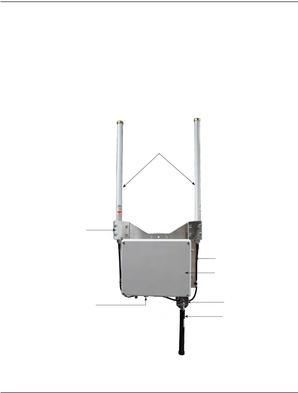
Figure 1: ORION SE II components
Transceiver Enclosure Cover
Backhaul Antenna Bracket
TX/RX Fiberglass
Antennas
GPRS Antenna
M12 Connection
(Included with all congurations
except LAN with PoE)
Antenna Mounting Bracket
Enclosure Bracket Connected to
Mounting Backplate
Page 8 October 2013

Installation Manual
Tools and Materials (Customer-supplied)
• Phillips #2 screwdriver
• Precision slotted screwdriver with a 2.0 millimeter (0.079 inch) blade size
• Two 9/16 inch or adjustable wrenches for mounting V-block clamps (standard mounting)
• BAND-IT® tool (refer to "Banding Mounting" on page 15) and instructions, a 1/2 inch wrench and a hammer for
large diameter pole mounting
• Wrench (for 1-1/16 inch gland nut and 1-1/16 inch dome nut)
• Pliers or strap wrench (for tightening the 15/16 inch OD backhaul antenna and other Type N connectors)
• 7/16 inch socket wrench for all other bolts and nuts
• Cat5e Ethernet cable (outdoor-rated) and RJ45 jack for LAN connection
Connecting the Battery Backup
The ORION SE II network gateway transceiver contains an onboard battery backup. The battery must be connected before the
gateway is installed and powered. Follow these steps to connect the battery backup.
OTE:NRefer to "Battery Backup Replacement" on page 32 for details on replacing the battery.
1. Using a #2 slotted or Phillips screwdriver, remove the
enclosure cover by unscrewing the four corner-cover
screws.
OTE:NThe battery is held in place by the enclosure
cover only. No other adhesive or locking
mechanism is used.
2. Carefully install the battery connector onto the circuit
board. Insert the connector only far enough so that the
connector latch engages. Verify that proper connector
polarity is observed.
3. Replace the enclosure cover. Tighten each of the four
cover screws to 16 inch-pounds, maximum. Be careful not
to overtighten any of the screws.
BE CAREFUL NOT TO CRIMP THE BATTERY
CONNECTOR CABLE WHEN REPLACING THE
ENCLOSURE COVER. Figure 2: Battery connection
Battery Connector
Battery Connection
Page 9 October 2013
ORION® SE II Network Gateway Transceiver
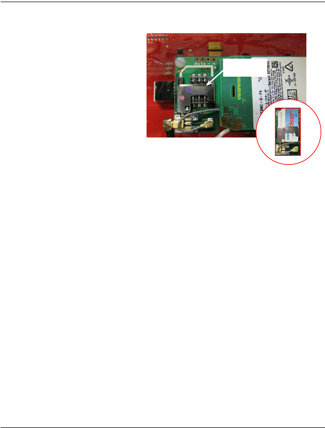
Installing the SIM Card (Customer-supplied)
A SIM card provides access to the cellular
provider network for the GPRS backhaul.
To install, slip the SIM card into the slot on
the green GPRS module, inside the enclosure,
on the gateway transceiver circuit board. An
outline of the SIM card is shown above the
slot (Figure 3). The outline shows the SIM card
notch on the left side.
Push the card into the slot (with the notch on
the left side) as far down as it will go. The SIM
card should look like the photo in the inset
circle when installed correctly.
Figure 3: SIM card slot
Attaching the GPRS Antenna
1. Remove the plastic cover from the Type N female connector on the backhaul antenna bracket.
2. Remove the backhaul antenna from the carton.
3. Thread the Type N male connector (antenna) onto the Type N female connector on the backhaul antenna bracket.
OTE:NRefer to "Backhaul Antenna Bracket" on page 13 for additional mounting information.
4. Hand tighten until nger tight. Then use pliers or a strap wrench to tighten an additional 1/16 inch turn (maximum).
Do not over-tighten or the connector can be damaged.
Insert SIM Card
Into Slot
Page 10 October 2013
Installation Manual
Gateway Mounting Backplate and Brackets
The gateway enclosure is permanently mounted to a bracket (PN: 67537-001) which is used to attach the gateway enclosure
to the backplate. When shipped, the gateway enclosure bracket is attached securely to the backplate.
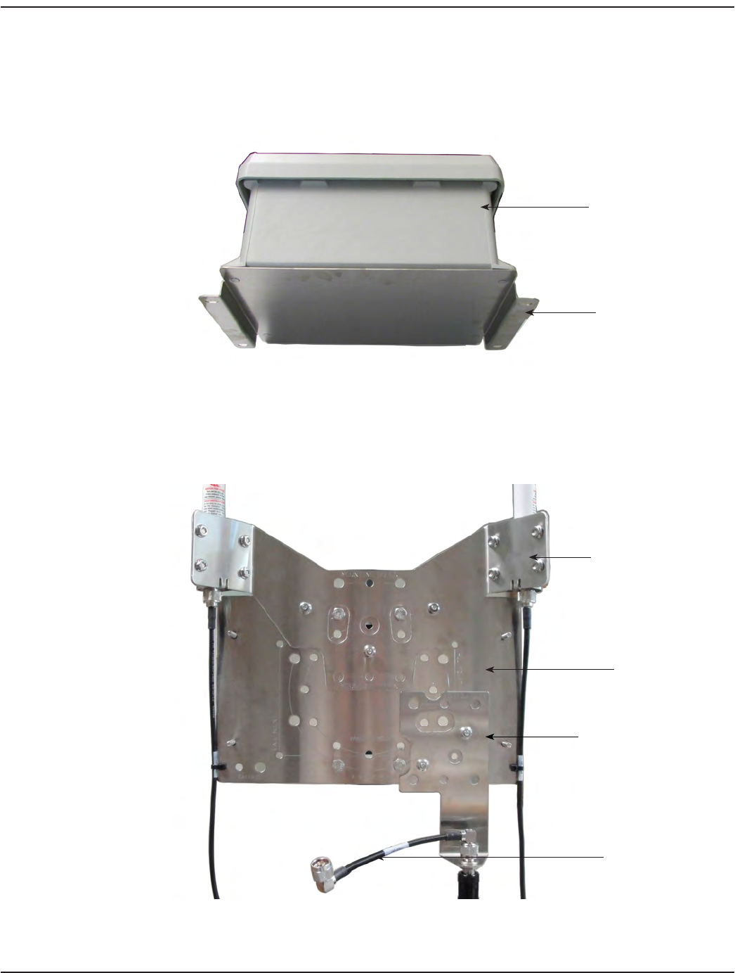
Figure 4: ORION SE II gateway transceiver with enclosure bracket
The backplate of the ORION SE II network gateway transceiver has a modular design consisting of three brackets joined
together. The brackets can be removed to provide additional mounting options. A description of each bracket starts on the
next page.
Figure 5: ORION SE II gateway backplate
Gateway Enclosure
Enclosure Bracket
Mounting Bracket
TX/RX Antenna Bracket
Backhaul Antenna Bracket
GPRS Antenna Cable
Page 11 October 2013
ORION® SE II Network Gateway Transceiver
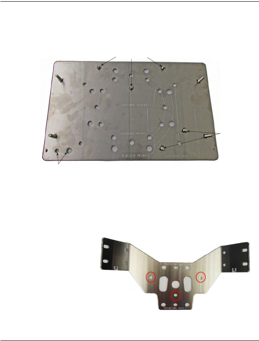
Mounting Bracket
The mounting bracket is machined with multiple holes to accommodate different mounting options. Mounting holes and the
V-Block, banding and wall mounting options are labeled on the bracket. The bracket also has 1/4 inch and 3/8 inch grounding
points (see Figure 6) which can be used if needed. When shipped, the mounting bracket, TX/RX antenna bracket and backhaul
antenna bracket are attached. Together they make up the backplate which is attached to the gateway enclosure bracket.
Figure 6: Mounting bracket
Mounting Options
The circular hole pattern on the mounting bracket can be used to accommodate mounting the gateway on an angled beam
or pole, if necessary.
The gateway can also be mounted on a wall. The mounting bracket has four .28 inch holes marked for this option.
OTE:NFor a wall mount, customers must supply mounting hardware suitable for the substructure on which the gateway
is mounted.
For all mounting options, all gateway installation considerations must be observed. Refer to "Specifications" on page 6.
TX/RX Antenna Bracket
When shipped, the TX/RX antenna bracket
is mounted to the top of the mounting
bracket with three locknuts
(PN: 67624-001). The mounting holes are
indicated in Figure 7.
Other holes on the bracket can be used
to accommodate remote installation.
For more information, refer to "Remote
Antenna Installation" on page 34 in
the Appendix.
Figure 7: TX/RX antenna bracket
Used to Mount Backhaul
Antenna Bracket
Used to Mount TX/RX
Antenna Bracket
Grounding Points
Page 12 October 2013
Installation Manual
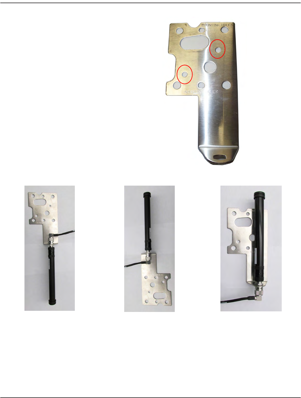
Backhaul Antenna Bracket
When shipped, the backhaul antenna
bracket (PN: 67536-001) is mounted to the
bottom of the mounting bracket with two
locknuts (PN: 67624-001). The mounting
holes are indicated in Figure 8.
Other holes on the bracket can be used
to accommodate remote installation. For
more information, refer to "Remote Antenna
Installation" on page 34 in the Appendix.
A backhaul antenna can be connected to
the bracket with either end up. However,
the antenna must always be connected at
the narrow end, hanging away from the
bracket as shown in Figure 9.
Figure 8: Backhaul antenna bracket
Correct Antenna Mount Correct Antenna Mount Incorrect Antenna Mount
Figure 9: Backhaul antenna mounting
X
Page 13 October 2013
ORION® SE II Network Gateway Transceiver
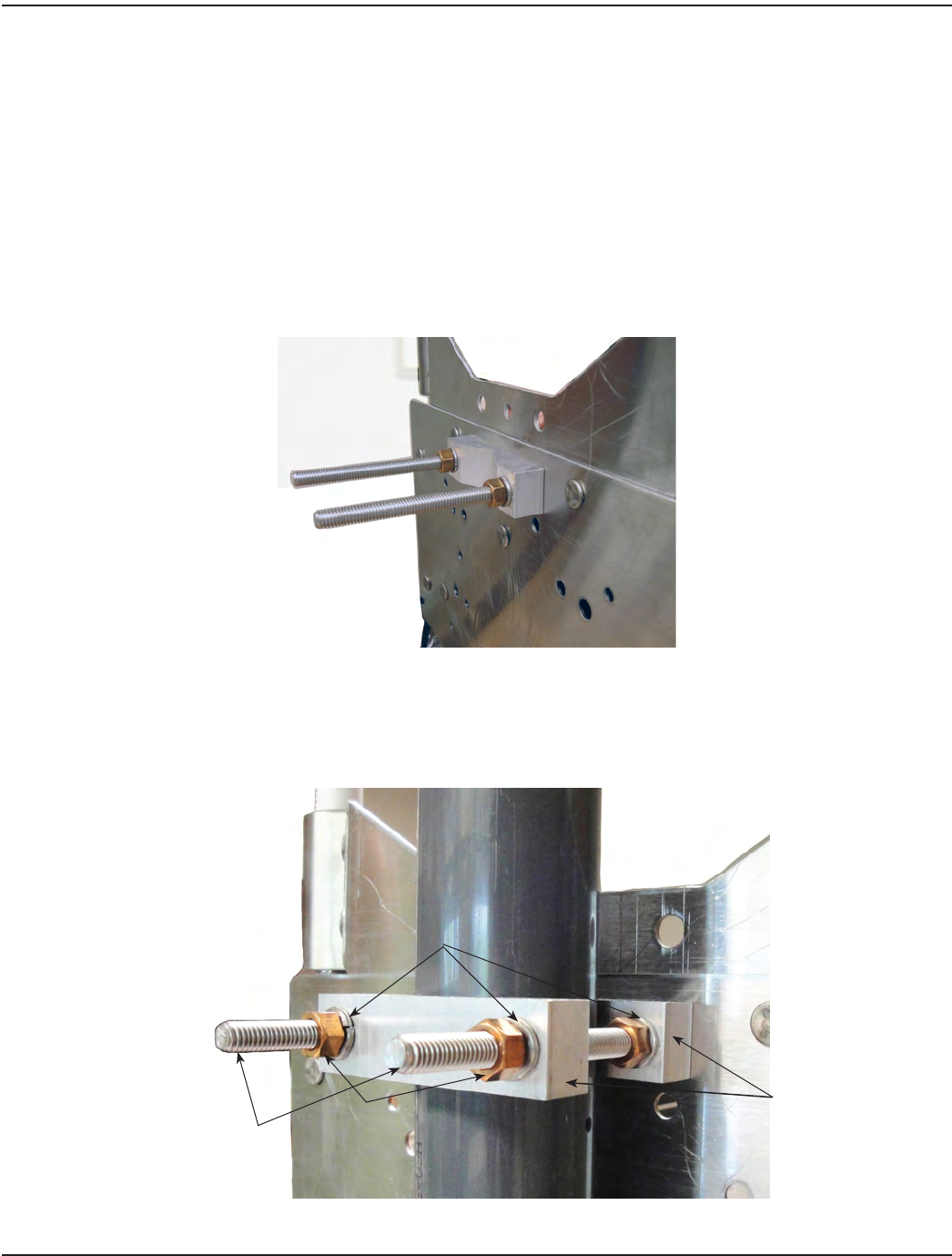
Using the V-block Clamps Mounting Hardware
The V-block mounting hardware is sized to mount the gateway on a vertical or horizontal pole with outer diameters ranging
from 1-1/4 inches to 2-1/2 inches. For mounting on poles larger than 2-1/2 inches, refer to "Banding Mounting" on page 15.
1. Open the bag of mounting equipment.
2. Place two bolts (3/8-16 x 5 inches) through the holes in the top of the gateway mounting backplate (Figure 10). Use
the backplate circular pattern holes for horizontal installation.
3. Place a clamp onto the bolts, as shown below.
4. Place a lock washer and nut onto each bolt, as shown below.
OTE:NThe lock washer and nut nearest the enclosure mounting bracket can be omitted when mounting on smaller
diameter poles to provide additional clamping distance.
Figure 10: Attach hardware
5. Tighten the two nuts with a 9/16-inch or adjustable wrench so that each lock washer is fully compressed and at.
6. Repeat Steps 2 through 5, attaching a clamp to the bottom of the gateway mounting backplate. Position the gateway
on the pole and place a clamp on the top bolts.
Figure 11: Transceiver positioning and clamps
Lock Washers
Nuts
Bolts
Clamps
Page 14 October 2013
Installation Manual
7. Place a lock washer and nut on each bolt and tighten the nuts 100…150 inch-pounds to ensure the gateway is
suciently secured to the pole.
8. Repeat Steps 7 and 8 for attaching the V-block clamp mounting hardware to the bottom bolts of the
mounting backplate.
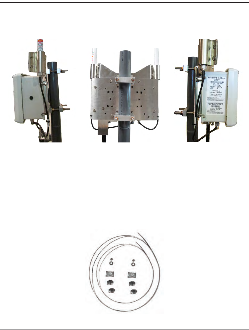
Side View Back View Side View
Figure 12: Completed gateway mounting
Banding Mounting
This mounting equipment is sized to mount the gateway on a 2-1/2…24-inch outer diameter pole.
MPORTANTI
When using the banding mounting kit for the gateway, use BAND-IT Idex installation practices. Refer to
www.band-it-idex.com/en/Literature/Tool_Instructions/P05886.pdf for more information. This is especially applicable when
mounting on a non-tapered vertical pole, as the banding could loosen over time resulting in the unit sliding down the pole.
To mount the gateway on a pole, gather the banding and locking equipment.
Figure 13: Banding and locking equipment
Page 15 October 2013
ORION® SE II Network Gateway Transceiver
OTE:NInstallation of banding mounting requires the use of the BAND-IT tool shown below (PN: 66042-006) or equivalent
BAND-IT tool as recommended by BAND-IT.
Figure 14: BAND-IT tool
1. Locate the BAND-IT tool and supplied installation instructions.
2. Follow the BAND-IT-supplied installation instructions enclosed with the BAND-IT tool for attaching the gateway
transceiver to a pole.
3. Using a 1/2 inch wrench, apply the recommended torque for the 5/16-24 screw that attaches the gateway bracket to
the BAND-IT banding. The recommended torque is 144…168 inch-pounds (12…14 foot-pounds).
Figure 15: Gateway shown with BAND-IT mounting hardware
Page 16 October 2013

Installation Manual
POWER SOURCE CONFIGURATIONS
Access to Power
• The ORION SE II network gateway transceiver requires access to power. The gateway can use a 120V AC grounded
outlet for use with the AC-to-DC power supply and power cord (PN: 66528-002), or a DC power source for use with
the DC power source cable with 308 in-line connector (PN: 66233-020). For a gateway with a LAN PoE configuration,
a Power over Ethernet connection is required. Diagrams of each power source configuration start on page 18.
• Outlet and enclosure (if required) should be mounted for easy accessibility by authorized utility personnel at the
installation site.
• Consult the appropriate electrical, building and industry codes, regulations and standards for accepted installation
practices for use of the AC-to-DC power supply and outlet in environmentally controlled indoor locations.
Use of a NEMA 4 Enclosure
AC-to-DC power supply used outdoors or in a non-environmentally controlled indoor location requires a customer-supplied
NEMA 4 enclosure, or equivalent, installed in accordance with appropriate electrical codes, building codes, industry codes,
regulations and standards.
Recommended Installation Congurations
These are the standard recommended installation configurations with various combinations of backhaul and power source:
• GPRS with 120V AC power source
• LAN with 120V AC power source
• GPRS with DC power source
• LAN with DC power source
• LAN with PoE power source
Diagrams of the above configurations are shown on the pages that follow. Consult the diagram for your
installation configuration.
Page 17 October 2013
ORION® SE II Network Gateway Transceiver
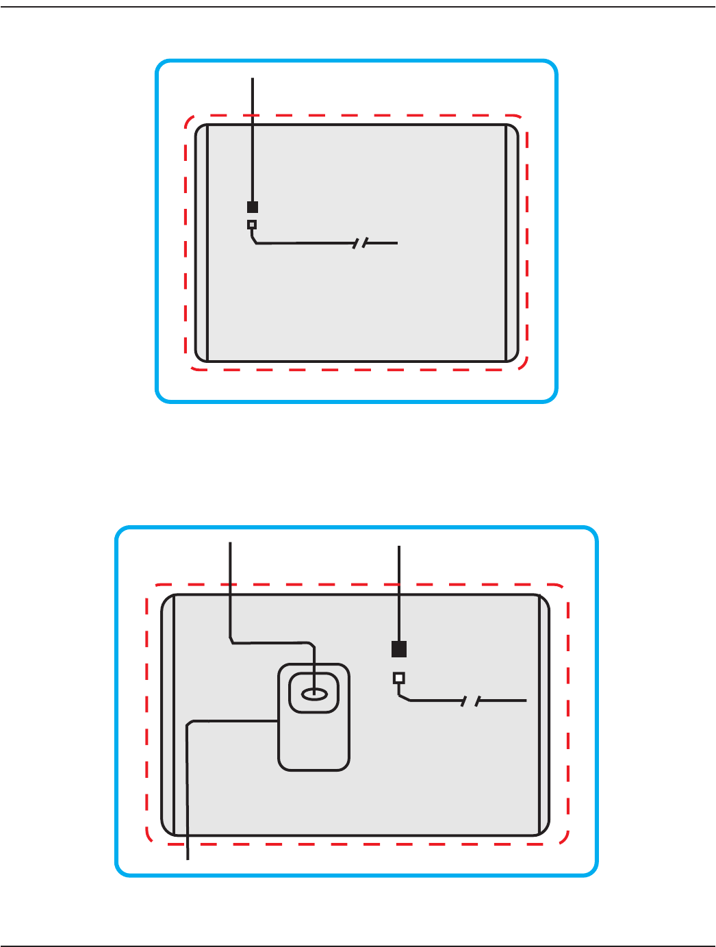
GPRS or LAN with 120V AC Power Source
Configurations for a 120V AC grounded outlet with GRPS and LAN are shown here.
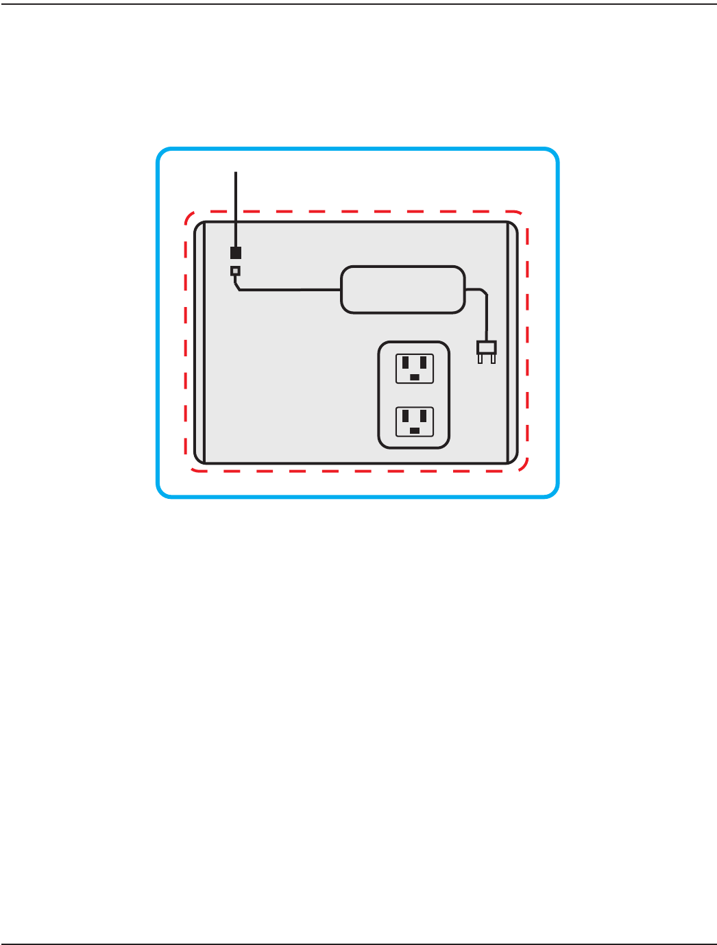
GPRS Connection with 120V AC Power Source
AC to DC Power Supply with
308 In-line Connector End and
Power Cord (supplied)
120VAC
Grounded Outlet
(customer
supplied)
Power Supply Cable with
308 In-line Connector
ORION SE Power Cable with
308 In-line Connector
(supplied)
Figure 16: GPRS connection with AC power source (*Shown with NEMA 4 enclosure)
*An enclosure may be recommended but is not included. If NEMA 4 enclosure or equivalent is required, as in an outdoor
installation, the minimum enclosure size is 12 inch x 10 inch x 6 inch (H x W x D).
Page 18 October 2013
Installation Manual
LAN with 120V AC Power Source
OTE:N Consult the manufacturer's installation and usage recommendations as well as appropriate codes, regulations and
standards for the LAN RJ45 Ethernet connection.
AC to DC Power Supply with 308
In-line Connector End and Power Cord
(supplied)
120VAC
Grounded Outlet
(customer
supplied)
To Utility
Network
Outdoor-rated
CAT5e Ethernet
Cable (customer
supplied)
LAN RJ45 Ethernet
Connection
(customer supplied)
Power Supply Cable with
308 In-line Connector
ORION SE Power Cable with
308 In-line Connector
(supplied)
Figure 17: LAN connection with AC power source (*Shown with NEMA 4 enclosure)
*An enclosure may be recommended but is not included. If NEMA 4 enclosure or equivalent is required, as in an outdoor
installation, the minimum enclosure size is 12 inch x 10 inch x 6 inch (H x W x D).
Page 19 October 2013
ORION® SE II Network Gateway Transceiver
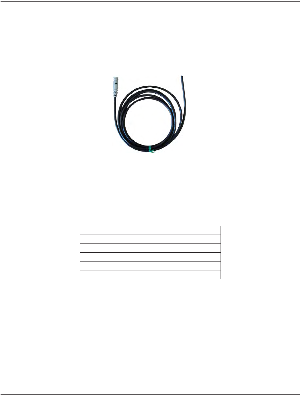
GPRS or LAN with DC Power Source
The ORION SE II network gateway transceiver can be ordered with a 10-foot DC power source cable (PN: 66233-020) for
direct connection with a customer-supplied DC power source. The gateway requires about 6W average power and 12W peak
power. When connecting an AC-to-DC power supply, the recommendation is to use a power supply rated at 1 A (minimum) at
24V DC.
OTE:NConsult the appropriate electrical, building and industry codes, regulations and standards for accepted installation
practices when attaching the cable to a DC power source.
Figure 18: 10' DC power cable
Absolute Requirements
The gateway can be powered by a DC voltage source between 12…30V. Cable length must be reduced to 100 feet, or less, if
less than a 24V source is being used. For reference, when connecting directly to batteries, as in a solar assembly (not supplied),
the average electrical load is 12V DC @ 0.5 A continuous. Cables, fuses and/or circuit breakers MUST be capable of handling at
least 1A peak currents.
External DC Power Source Connections
Wire Color for 66233-020 External DC Power Source
Drain (no insulation) Negative (–)
Black Negative (–)
Brown Negative (–)
Red Positive (+)
Light Blue Positive (+)
Page 20 October 2013
Installation Manual
GPRS Connection with DC Power Source
DC Power Source
(customer supplied)
10-foot DC Power Source Cable
with 308 In-line Connector End
(supplied)
ORION SE Power Cable with
308 In-line Connector
(supplied)
Figure 19: GPRS connection with DC power source (*Shown with NEMA 4 enclosure)
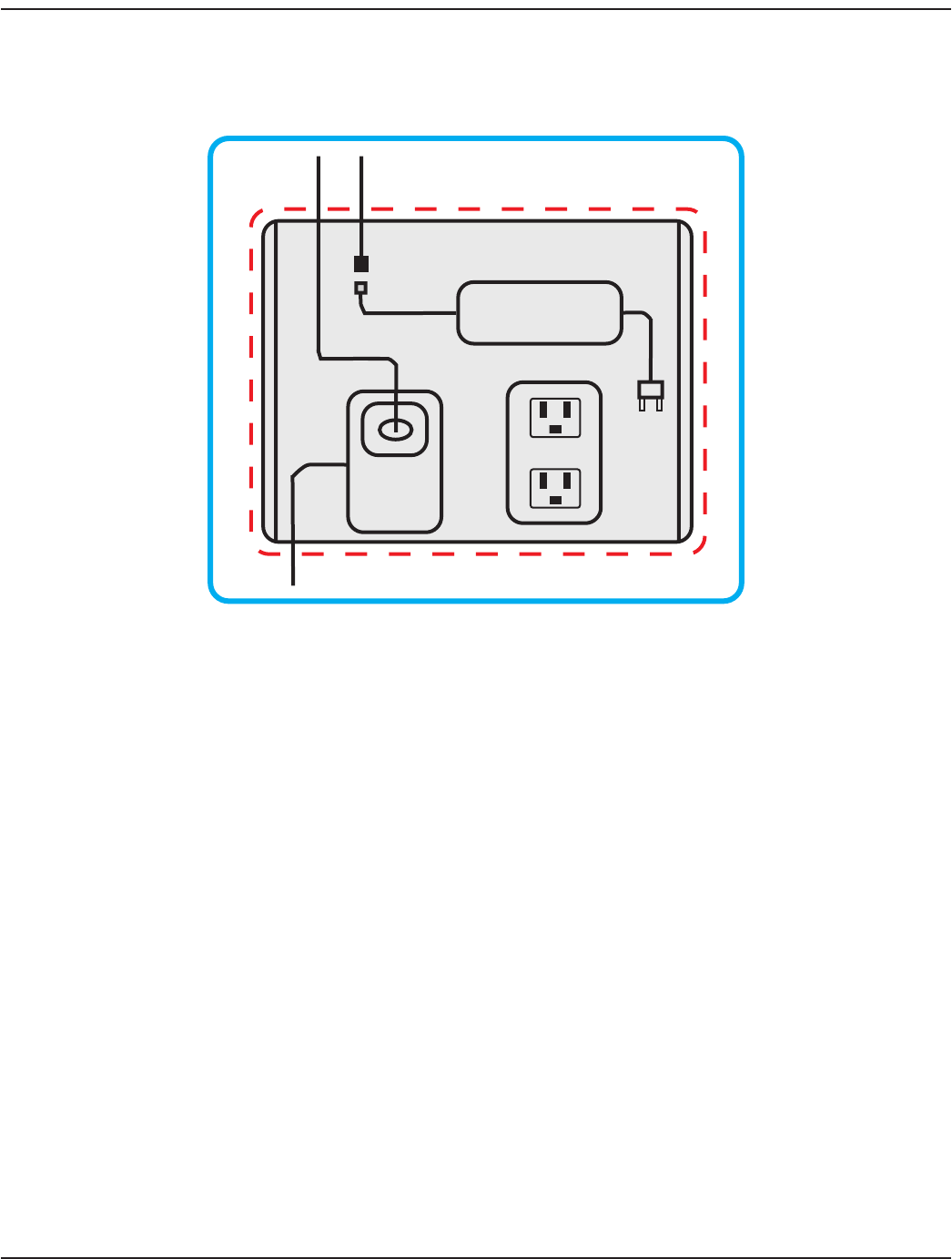
LAN Connection with DC Power Source
OTE:NConsult the manufacturer's installation and usage recommendations as well as appropriate codes, regulations and
standards for the LAN RJ45 Ethernet connection.
DC Power Source
(customer supplied)
CAT5e Outdoor-rated
Ethernet Cable
(customer supplied)
LAN RJ45 Ethernet
Connection
(customer
supplied)
To Utility
Network
10-foot DC Power Source
Cable with 308 In-line
Connector End (supplied)
ORION SE Power Cable with
308 In-line Connector End
(supplied)
Figure 20: LAN connection with DC power source (*Shown with NEMA 4 enclosure)
*The enclosure may be recommended but is not included. If NEMA 4 enclosure or equivalent is required, as in an outdoor
installation, the minimum enclosure size is 12 inch x 10 inch x 6 inch (H x W x D).
Page 21 October 2013
ORION® SE II Network Gateway Transceiver
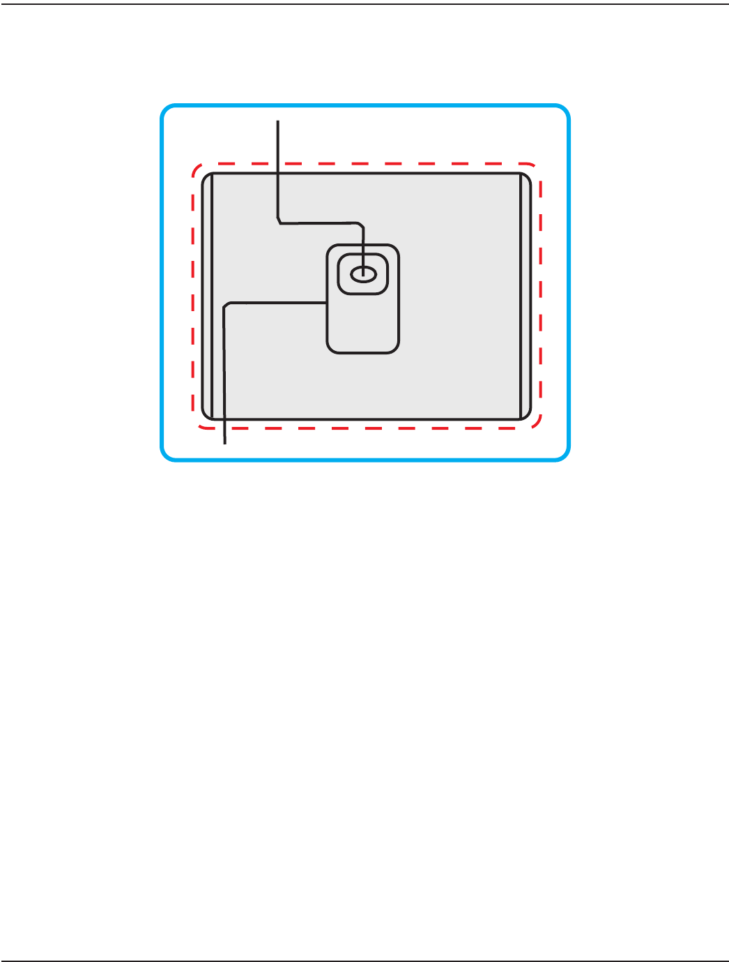
LAN with Power Over Ethernet (PoE) Power Source
OTE:N Consult the manufacturer's installation and usage recommendations as well as appropriate codes, regulations and/or
standards for the LAN RJ45 Ethernet connection.
To Utility
Network
CAT5e Outdoor-rated
Ethernet Cable
(customer supplied)
PoE LAN RJ45
Ethernet
Connection
(customer
supplied)
Figure 21: LAN with PoE power source connection (*Shown with NEMA 4 enclosure)
*An enclosure may be recommended but is not included. If NEMA 4 enclosure or equivalent is required, as in an outdoor
installation, the minimum enclosure size is 12 inch x 10 inch x 6 inch (H x W x D).
Page 22 October 2013
Installation Manual
ELECTRICAL CONNECTIONS
M12 Connector Assembly
The M12 connector assembly is required for all power source configurations except LAN with PoE.
OTE:NUse only approved Badger Meter power cable, 100-foot (PN: 66233-015) or 300-foot (PN: 66233-017), for
this assembly.
Tools and Materials
Included with gateway:
• M12 plug, 8-conductor connector (PN: 66525-002)
• Badger Meter power cable, 100-foot or 300-foot, with 308 in-line connector end
• 308 in-line connector anti-tamper collar
Customer-supplied:
• Coax stripper (customer-supplied)
• Wire stripper for 22 AWG wires (customer-supplied)
• Precision slotted screwdriver with blade size of 2.0 millimeter (0.079 inch) (customer-supplied)
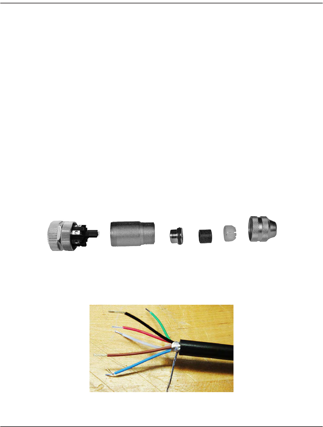
M12 Plug Connector Part Names
Figure 22: M12 plug connector parts
1. Push the connector parts onto the power cable in the following order: pressure nut, clamping cage, cable seal, sleeve
with O-ring and nally, the coupling sleeve.
2. Strip the cable outer jacket to a maximum length of 1.1 inches.
Figure 23: Stripped cable wires
3. Shorten the foil shield ush with the outer jacket.
Female Insert Coupling Sleeve Sleeve
w/O-ring Cable
Seal
Clamping
Cage
Pressure
Nut
Page 23 October 2013
ORION® SE II Network Gateway Transceiver
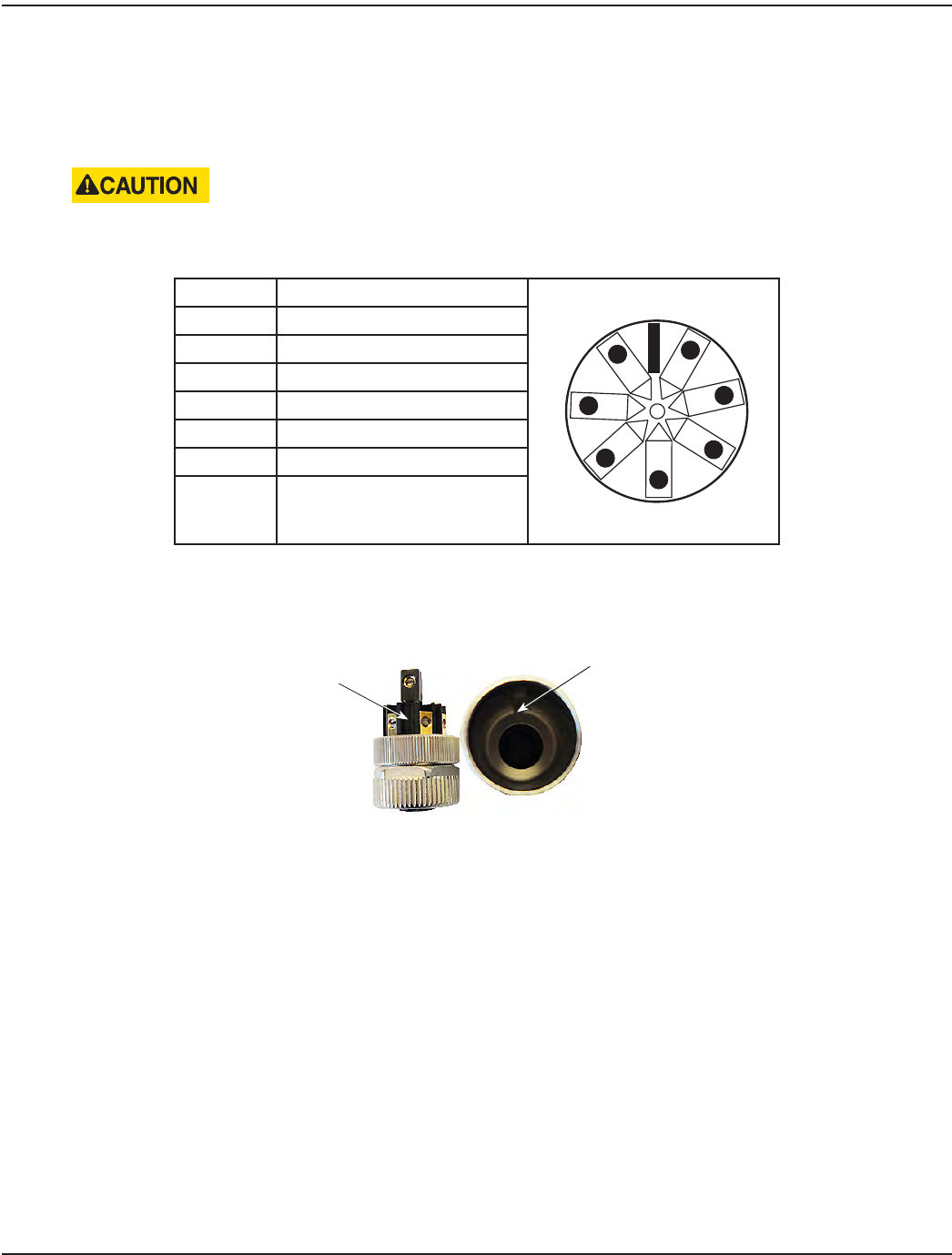
4. Strip the ends of the six (6) colored wires to a length of 1/8 inch. Twist the conductors on each wire.
5. Shorten the drain/bare wire (no insulation) to 11/16 inch.
6. Loosen each screw (about 2…3 turns) on the female insert and attach the wires to the female insert using the chart
below. Retighten each screw after the wire has been connected.
BE CAREFUL NOT TO BACK THE SCREWS OUT TOO FAR. THE SCREWS ARE SMALL AND CAN EASILY BE LOST IF
THEY ARE DROPPED.
Wire Female insert connector
Slot
Red
1
2
3
4
5
7
8
Brown
Black
White
Green
8 (center) is for the shield-drain
M12 Connector Wire Contact View
Blue
White 4
Drain 8 (Center)
Black 3
Blue 7
Red 1
Green 5
Brown 2
7. Assemble the female insert to the coupling sleeve by aligning the female insert tab slot with the notch in the
coupling sleeve.
Figure 24: Slot alignment
Female Insert
Tab Slot
Coupling Sleeve Insert
Notch
Page 24 October 2013
Installation Manual
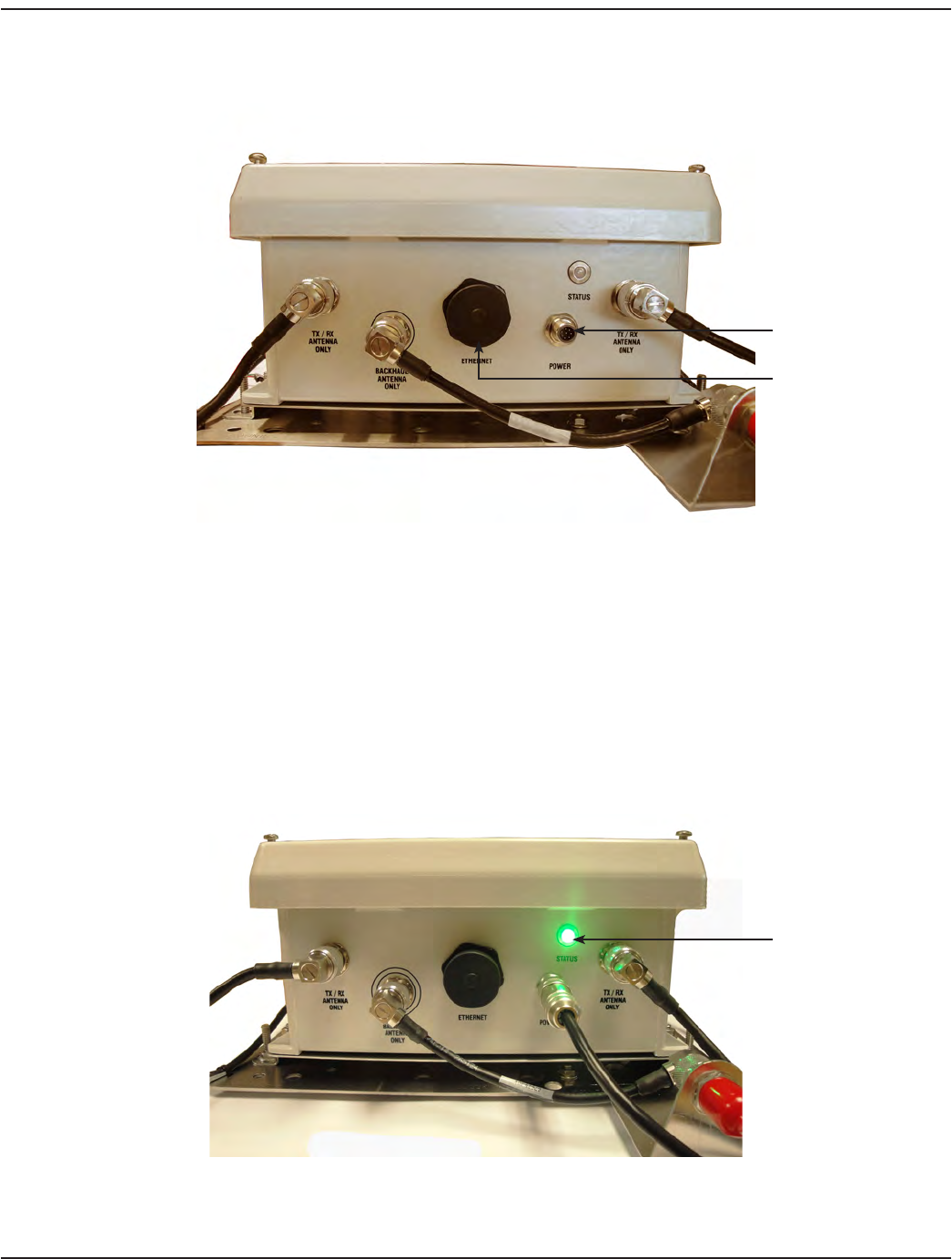
8. Remove and discard the cap from the M12 receptacle on the bottom of the gateway transceiver.
Figure 25: Bottom of gateway transceiver
9. Connect the M12 plug connector assembly to the M12 receptacle and tighten the locking ring in a clockwise
direction until nger tight.
10. Connect the 308 connector on the other end of the power cable to the 308 connector of the AC-to-DC power supply
and snap the anti-tamper collar over the connection.
11. Connect the power cord to the power supply and then plug the three-prong male end of the power cord into a
120V AC power source. The LED indicator above the M12 connection turns on with a steady green light, indicating
the gateway is being AC powered (Figure 26).
OTE:NA red blinking light indicates the gateway is being powered only by the internal backup battery.
No light indicates the gateway is not receiving AC or backup battery power.
Figure 26: Gateway on AC power
The M12 connection is complete.
M12 Receptacle
with Cap Removed
RJ45 Receptacle
Gateway on
AC Power
Page 25 October 2013
ORION® SE II Network Gateway Transceiver
AC Power
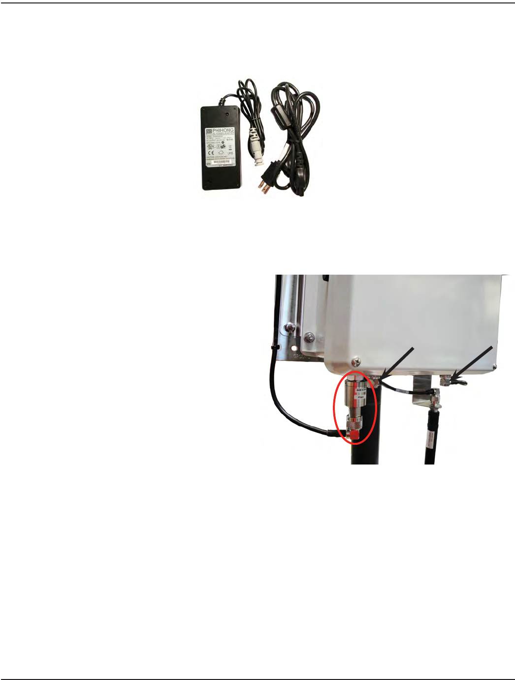
Badger Meter provides an AC-to-DC power supply with cord (PN: 66528-002) that plugs into a standard three-prong
120V AC outlet.
Figure 27: 120V AC power supply with power cord
OTE:NIf you are powering the gateway directly via DC power, refer to "GPRS or LAN with DC Power Source" on page 20 .
Lightning Arrestors
Lightning arrestors are recommended for all standard and
remote antenna installations. If lightning arrestors are
used, they should be placed directly between the gateway
enclosure and the antenna cable connector and grounded
per code. One lightning arrestor is shown in Figure 28. Arrows
indicate where other lightning arrestors should be attached.
Lightning arrestors for both the TX/RX antennas as well as
the GPRS backhaul antenna (if applicable), should meet the
following specifications:
• Operating bandwidth: 800…2400 MHz
• Impedance: 50 ohms
• Power handling (average): 2 watts, minimum
• Environmental/weather rating suitable for
the location
• N male connector on the protected side;
N female connector on the surge side
Figure 28: One attached lightning arrestor (Ground is not
pictured). Arrows indicate where additional lightning arrestors
should be attached.
Page 26 October 2013
Installation Manual
RJ45 Plug Assembly for LAN Connectivity
Use this procedure to connect an Ethernet cable to the gateway for a LAN backhaul or any PoE connection.
Required Supplies:
• RJ45 Plug Assembly (PN: 66527-001) as shown in Figure 29
• Cat5e Ethernet cable (limited to 300 feet of outdoor-rated cable) and available LAN connection (customer-supplied)
• Wrenches – 1-1/16 inch (customer-supplied)
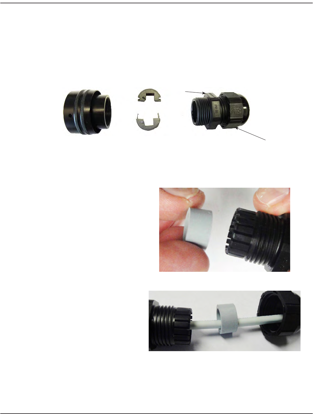
Figure 29: RJ45 plug components
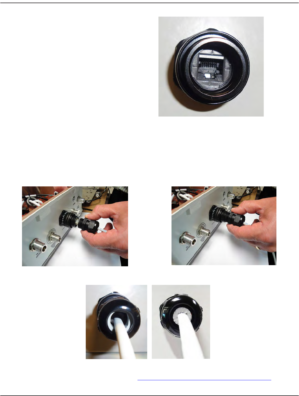
1. Separate the RJ45 plug pieces:
• Unscrew the cable gland from the metal
housing and put the metal housing
aside for use in step 4.
• For ease of installation, remove the gray
seal from inside the cable gland body as
shown in Figure 30.
Figure 30: Remove gray seal
2. In the following order, thread the dome nut,
gray seal and cable gland body onto the
Ethernet cable as shown in Figure 31.
Figure 31: Thread nut, seal and cable gland
3. Reassemble the parts on the Ethernet cable
by reinserting the gray seal into the cable
gland body and loosely screwing the dome
nut onto the cable gland body.
OTE:NDo not screw together tightly at
this time.
Cable Gland
Nut
Dome Nut
Metal Housing Insulator Halves Cable Gland
Page 27 October 2013
ORION® SE II Network Gateway Transceiver
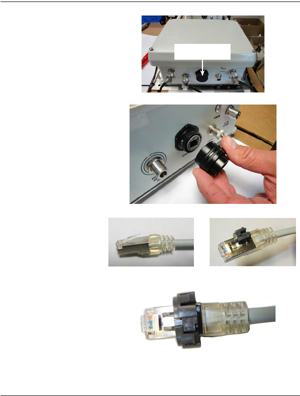
4. Attach the metal housing to the
RJ45 receptacle on the gateway:
• Remove the RJ45 receptacle
bayonet lock cap from the
gateway by turning the cap
1/4 turn counter clockwise.
OTE:NThe RJ45 receptacle cap
should be saved so it can be
replaced if the Ethernet cable
is removed later.
• Place the metal housing on
the RJ45 receptacle and turn
it until you feel the metal
housing align with the keys
on the RJ45 receptacle
(Figure 33).
Once aligned, tighten the
outer sleeve on the metal
housing 1/4 turn clockwise.
OTE:NThe metal housing fits on
the RJ45 receptacle correctly
when it is aligned with the
keys on the RJ45 receptacle.
Figure 32: Bayonet lock cap
Figure 33: Remove bayonet lock cap
5. Attach the half insulators to
the RJ45 modular plug on the
Ethernet cable connector:
• Hold down the plug latch and
slide one of the half insulators
over the latch. Make sure the
half insulator prong is aligned
next to the plug latch as
shown in Figure 35.Figure 34: Plug latch Figure 35: Half insulator over latch
• Slide the other half insulator
over the other side of the
latch while holding the half
insulator you just attached,
again making sure the
prong is aligned next to the
plug latch.
• Squeeze both insulators
together to connect. You
will hear a “click” when the
connection is made. The plug
with both half insulators is
shown in Figure 36.
Figure 36: Half insulators connected
RJ45 Receptacle Bayonet
Lock Cap
Page 28 October 2013
Installation Manual
6. Insert the Ethernet cable connector into
the RJ45 receptacle. Push the connector
in rmly.
The plug latch of the connector ts into
the recessed key section of the RJ45
receptacle. A close-up view from the front
is shown in Figure 37.
An audible click conrms a
complete connection.
OTE:NOnce assembled, RJ45 plugs cannot be
disassembled from the metal housing
without a special tool (PN: 67163-001).
Figure 37: RJ45 receptacle close up
7. Screw the cable gland onto the metal housing on the RJ45 receptacle and tighten the cable gland nut.
See Figures 38 and 39. Recommended: Use a torque wrench to tighten to 30…45 inch-pounds.
8. Tighten the dome nut on the cable gland (Figure 39). Recommended: Use a torque wrench to tighten to 20 inch-pounds.
OTE:NThe gray seal inside the dome nut must be in firm contact with the Ethernet cable. As the dome nut is tightened,
the seal should fill the open end of the dome nut without popping out the front and should be in firm contact
with the outer jacket of the Ethernet cable. See Figures 40 and 41.
Figure 38: Screw cable gland onto metal housing Figure 39: Tighten the cable gland nut
Figure 40: Gray seal before dome nut is tightened Figure 41: Gray seal after dome nut is tightened
Assembly is complete. For additional information, refer to http://www.rjfield.com/Ethernet_connectors_rjf_en.htm.
Page 29 October 2013

ORION® SE II Network Gateway Transceiver
GPRS DUAL BACKHAUL CONFIGURATION
ORION SE II network gateway transceivers are configured to allow a dual backhaul connection so you can switch from GPRS to
an alternative LAN backhaul, if necessary, using the RJ45 plug assembly included with the transceiver.
The GPRS connection can remain in place when the LAN connection is set up. Refer to "LAN with 120V AC Power Source" on
page 19 for the LAN installation diagram.
OTE:NThe gateway will need to be reprogrammed for a LAN connection. Refer to the Gateway Configuration Software
manual available at www.badgermeter.com, for programming instructions.
Page 30 October 2013

Installation Manual
APPENDIX
Page 31 October 2013
ORION® SE II Network Gateway Transceiver
BATTERY BACKUP REPLACEMENT
If a battery replacement is required, complete the installation steps as detailed below in the order presented.
OTE:NIt is not necessary to disconnect AC power from the gateway before removing the cover and replacing the battery.
Tools and Materials
• Rechargeable battery pack kit with enclosure cover (PN: 67018-001)
• #2 slotted or Phillips screwdriver (customer-supplied)
MPORTANTI
Working with electronics requires the use of proper electrostatic discharge (ESD) protection. Grounded wrist straps are
recommended when working inside the enclosure.
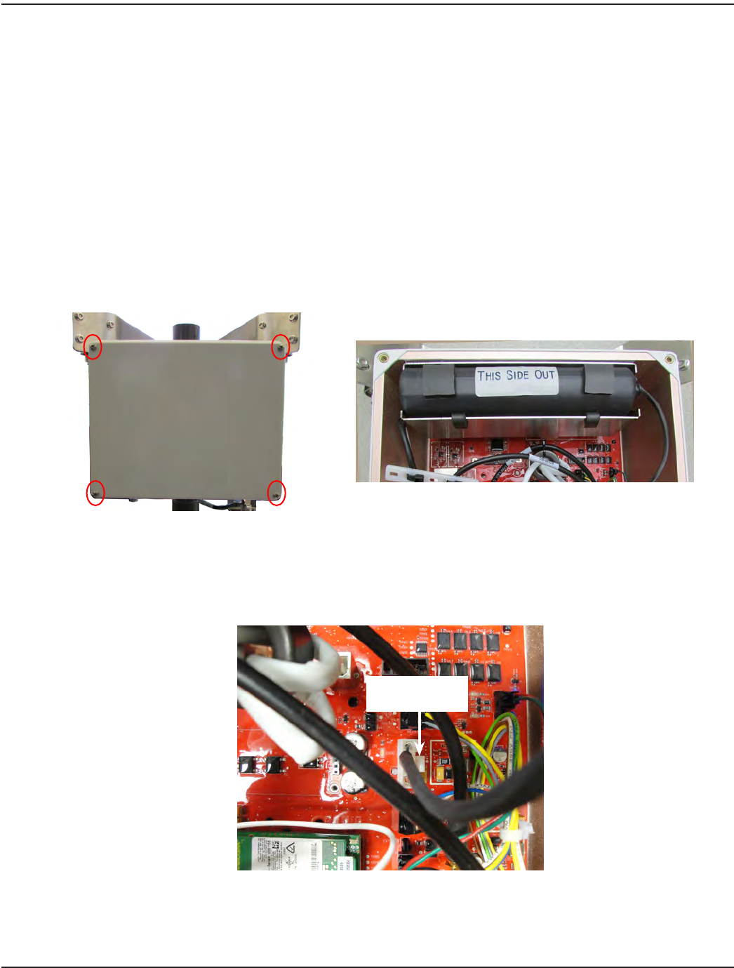
1. Using a #2 slotted or Phillips screwdriver, remove the enclosure cover by unscrewing four corner-cover screws
(Figure 42). The cover will not be used again and can be discarded.
Remove Four Corner Screws
Cover Removed
Figure 42: Enclosure cover removal
2. Squeeze the connector latch (Figure 43) of the battery connector on the circuit board and carefully pull on the
connector to remove it from the circuit board pin contacts. Do NOT pull on the connector wires. If the connector is
stuck, it can need to be gently rocked back and forth while pulling.
Figure 43: Battery connector
OTE:NThe battery is held in place by the enclosure cover only. No other adhesive or locking mechanism is used.
Battery Connector
Latch
Page 32 October 2013
Installation Manual
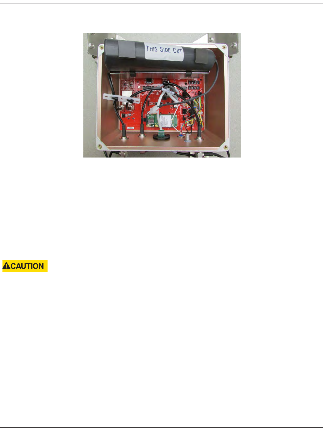
3. Grasp and pull to remove the battery from the unit (Figure 44) and safely discard the battery (see "Battery Disposal"
on page 33).
Figure 44: Battery removal
4. Place the new battery into the enclosure with the battery label “This Side Out” visible, as shown.
5. Carefully install the battery connector onto the circuit board. Insert the connector only far enough so that the
connector latch engages. Verify that proper connector polarity is observed.
6. Install the new enclosure cover provided with the battery kit. Tighten each of the four cover screws to
16 inch-pounds, maximum, being careful to not overtighten any of the screws.
Battery Disposal
The battery contains lead and should be handled and disposed of in accordance with local, state and federal regulations.
Refer to Badger Meter Battery Handling Safety Guide MRT-SG-02, available at www.badgermeter.com, for more information.
FAILURE TO PROPERLY DISPOSE OF A LEAD ACID BATTERY MAY RESULT IN BODILY HARM AND/OR PROPERTY DAMAGE
FROM ACID BURNS.
Page 33 October 2013

ORION® SE II Network Gateway Transceiver
REMOTE ANTENNA INSTALLATION
This section provides instructions for installing the TX/RX antennas and/or the backhaul antenna separately from the
ORION SE II network gateway transceiver.
The ORION SE II network gateway transceiver (“gateway”) is designed to allow remote antenna mounting. The gateway ships
in a direct mount configuration but the antennas can be separated from the enclosure assembly and remotely mounted using
the antenna mounting bracket and antenna cables and connectors as defined in the Badger Meter specifications. Antenna
cables and cable connectors are to be installed and mounted per cable and connector manufacturer instructions.
MPORTANTI
Professional installation of the ORION SE II Network Gateway Transceiver per Badger Meter installation instructions is required.
Installation, mounting and disposal shall be in accordance with all local, state and federal regulations. When installing the
network gateway transceiver, the customer is responsible for complying with local, state and federal codes and guidelines as well
as applicable industry standards, such as ANSI/TIA/EIA 222 (structural standards for steel antenna towers and antenna supporting
structures) and the National Electrical Code (NEC). Proper grounding is necessary, and in the case of a wooden pole, a dedicated
copper ground wire should be used for lightning protection.
OTE:NThe ORION SE II Network Gateway Installation Form in this manual must be completed for each installation and
returned to Badger Meter. The three-page form starts on page 43.
Antenna Maximum Distance
• Distance maximum for remote
TX/RX antennas
Up to 200 feet maximum from the gateway enclosure
• Distance maximum for remote
backhaul antenna
Up to 100 feet maximum from the gateway enclosure
Remote Installation Additional Parts
The following parts have been approved by Badger Meter and are required for remote antenna installations at the distances
indicated. Make sure all required parts are ready to use before starting a remote installation. Substitutions are not allowed.
OTE:NParts are supplied by the installation contractor unless otherwise marked.
Antenna Distance
(feet)
Antenna Coaxial
Cable
Cable Connectors Remote Flex Cable Remote Antenna Mounting
Bracket Kits
(One kit required per
antenna bracket)
TX/RX 0…60' Times Microwave
LMR-400-DB
(2 per gateway)
Times Microwave
EZ-400-NMH-X
(4 per gateway)
N/A
V-block Mounting Kit
(PN: 66681-001*)
Banding Mounting Kit
(PN: 66042-004*)
TX/RX 61…200' CommScope®
AVA6-50
(2 per gateway)
CommScope
114EZNF
(4 per gateway)
Coax cables kit
P/N: 67809-001*
(1 kit with 4 cables
per gateway)
Backhaul
(GPRS)
0…100' Times Microwave
LMR-400-DB
(1 per gateway)
Times Microwave
EZ-400-NMH-X
(2 per gateway)
N/A
*Order part/kit from Badger Meter
Page 34 October 2013
Installation Manual
Assembly Size, Weight, Wind Loading
Refer to "Specifications" on page 6 for the complete specifications list.
Height Width Depth Weight Wind
Loading
Area
Direct Mount
Antennas Assembly
(includes gateway enclosure,
TX/RX antennas, backhaul antenna and
mounting brackets)
43.8" 15.5" 6.5" 23.2 lb 1.5 ft2
Remote Mount
Antennas Gateway enclosure with mounting bracket 10.3" 14.5" 6.5" 17.5 lb 1.0 ft2
TX/RX antennas with mounting bracket 21.3" 15.5" 2.9" 4.8 lb 0.8 ft2
Backhaul antenna with mounting bracket 16.6" 4.2" 2.1" 0.9 lb 0.2 ft2
Mounting Hardware
V-Block mounting kit 1.6 lb
Banding mounting kit 1.0 lb
Weatherproofing for Connector/Cable Connections
Weatherproofing material should be provided by the installation contractor. Badger Meter recommends weatherproofing
for all connections according to cable and connector manufacturer recommendations. Weatherproofing provides additional
moisture protection and will prevent the connections from loosening due to vibrations.
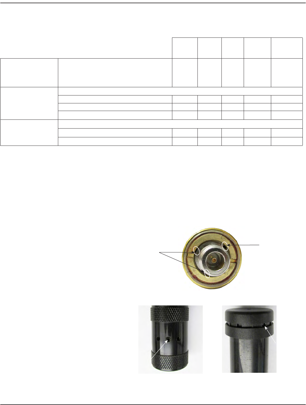
MPORTANTI
All external antennas are designed with vent holes. Any weatherproofing applied to the Type N connectors must not obstruct this
venting or the antenna can be damaged.
• On the TX/RX antennas, small vent
holes are located at the bottom end of
the antenna, next to the Type N female
connector as shown in Figure 45.
Figure 45: Vent holes at bottom of TX/RX antenna
• On the backhaul antenna, the vent holes
are located at each end (Figure 46). At
the bottom end with the Type N male
connector, the vent holes are on the
outside, on the metal section. At the top,
the holes are incorporated into the cap.
Figure 46: Vent holes at bottom and top of backhaul antenna
Vent Holes
Vent Hole
Vent Hole
Vent Hole
Page 35 October 2013

ORION® SE II Network Gateway Transceiver
Installation Considerations
To help maximize the performance of the ORION SE fixed network system, the following installation guidelines and
recommendations should be considered when selecting mounting locations for gateways.
The utility is responsible for properly positioning the gateway. For optimal reception and transmission, locate the gateway
transceiver and antennas in line-of-sight view of the desired endpoints.
• Avoid installing the gateway or remotely mounted antennas next to or between objects such as tall buildings,
towers, bridges, highway overpasses or signs that obstruct line of sight with the endpoints.
• Avoid installing the gateway or remotely mounted antennas near RF transmitters or other sources of RF radiation
including high-power in band and near-power sources such as pagers, cellular 900 MHz transmitters and
communications transmitters. Other potential sources of RF radiation include power line transformers, neon or
fluorescent signs, RADAR transmitters and SCADA systems. If the gateway is to be located near other RF radiators, a
minimum distance of 100 feet horizontal separation and 10 feet vertical separation must be maintained between the
gateway and the source of RF radiation.
• Mount the gateway as high as possible above average terrain, within the limits of the 300-foot power cable, and
maintain a 360 degree view of the horizon.
• Minimum standoff distance of two (2) feet from any structure is required.
• The gateway transceiver or remotely mounted antennas should be positioned no closer than 25 feet from the
nearest endpoint.
• Avoid installing the gateway transceiver antennas inside metal enclosures or inside of a building as the antennas
cannot communicate if surrounded by metal.
Required Antenna Tests
Once the antennas have been installed, but prior to attaching the antenna assembly to the gateway enclosure, the
installation contractor must take a VSWR reading on the remotely mounted antenna system. The actual measurement should
be recorded and provided to Badger Meter as part of the installation information for each gateway.
• For the TX/RX antennas, the VSWR meter should be set to 915 MHz.
• For the backhaul antenna, the VSWR meter should be set to 900 MHz.
• VSWR measurement 1:1…2:1 (for example, 1.2:1, 1.5:1 or 1.9:1) is acceptable.
Any objects that come into contact with the antenna during this test will affect the outcome of the VSWR measurement.
In order to properly make this measurement, the antenna must be located in free space (holding the antenna by the cable
below the Type N connection is acceptable), away from any metallic objects.
OTE:N All installation cables and devices (for example, lightning arrestor) must be included for the VSWR measurement.
Report the VSWR reading to Badger Meter for each installation using the ORION SE II Network Gateway Installation Form. The
three-page form starts on page 43.
Page 36 October 2013

Installation Manual
Required Installation Pictures
The installation contractor is required to provide electronic images of each gateway installation to Badger Meter as follows.
• View from the ground to the remote antennas
• 360-degree view (north/south/east/west-facing) from the antenna mounting structure and from the
gateway enclosure
• Pictures showing any other antennas in the proximity of the gateway antennas as well as potential obstructions
Refer to the ORION SE II Network Gateway Installation Form for a complete list of required photos. The three-page form starts
on page 43.
Page 37 October 2013
ORION® SE II Network Gateway Transceiver
Remote Antenna Installation Instructions
Remote antenna installations must be performed by a professional installation contractor to ensure compliance with
FCC regulations.
FAILURE TO READ AND FOLLOW THE INSTRUCTIONS PROVIDED CAN LEAD TO MISAPPLICATION OR MISUSE OF THE
ORION SE II NETWORK GATEWAY TRANSCEIVER, RESULTING IN PERSONAL INJURY AND DAMAGE TO THE EQUIPMENT.
1. Unpack the ORION SE gateway assembly from the
box. Locate and retain any accessories packaged
with the gateway.
OTE:N The GPRS backhaul antenna is not
connected when shipped.
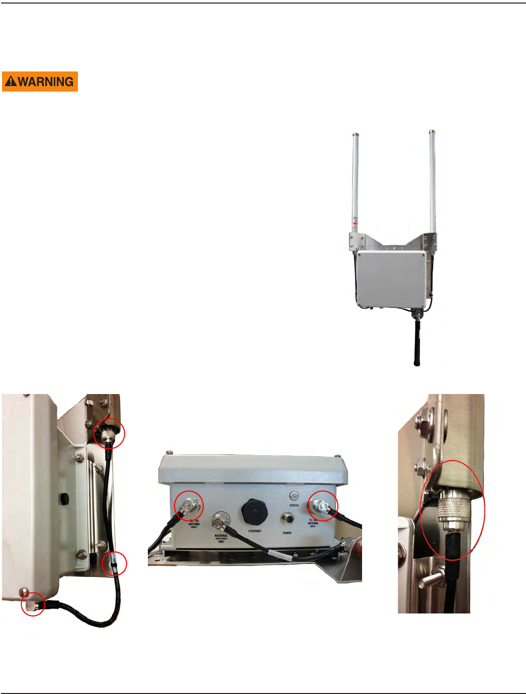
2. For each TX/RX antenna, cut and remove the
cable ties holding the antenna cable to the
gateway enclosure.
Disconnect the TX/RX antenna cable/connector
assembly from connectors located on the enclosure
and base of each antenna (Figure 48).
Figure 47: Gateway assembly with GPRS antenna
Figure 48: Disconnect cables and connector assemblies
3. Remove the antenna cable/connector assemblies but retain for future use should direct connection of the antennas
be required in the future.
Page 38 October 2013
Installation Manual
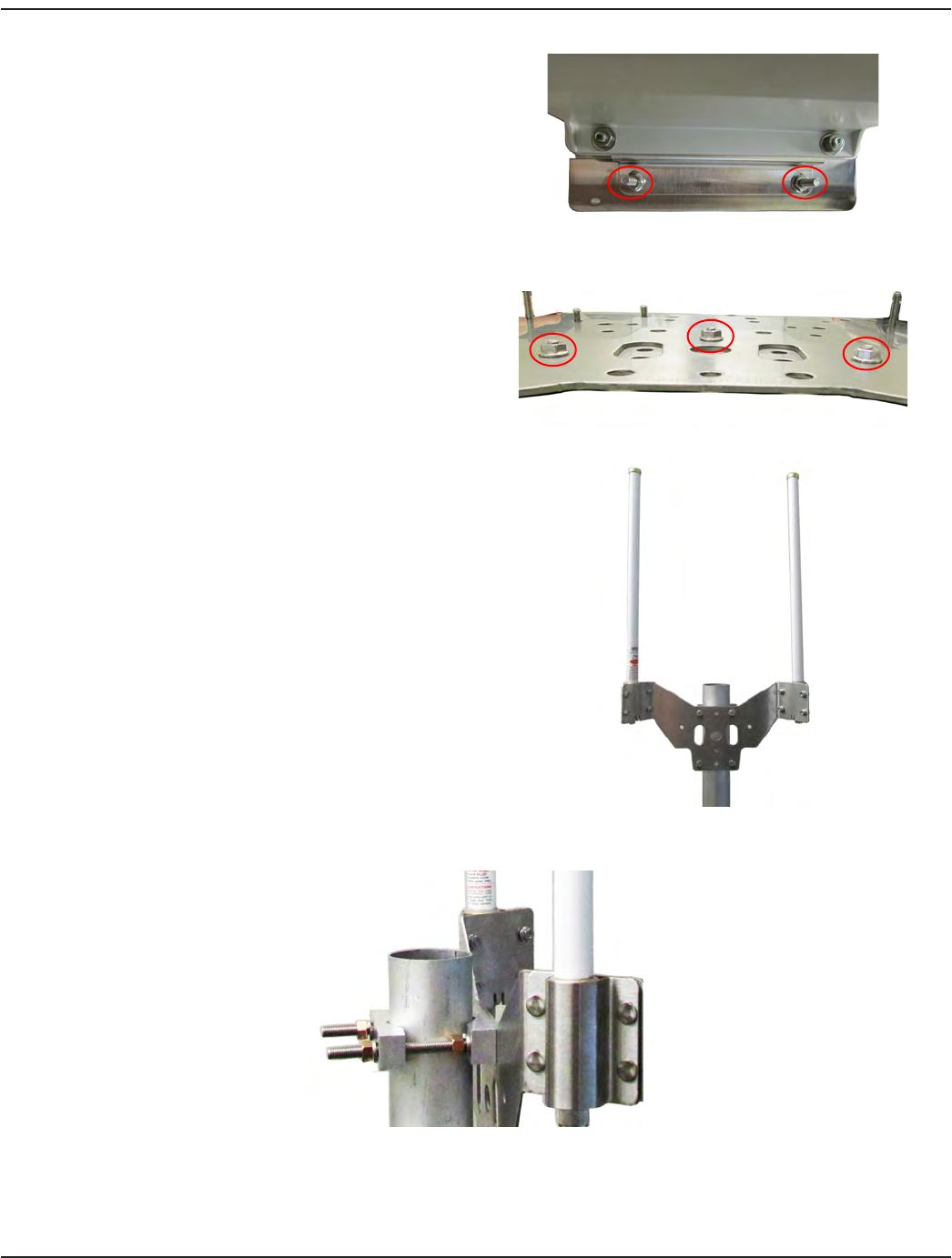
4. Disconnect the enclosure from the backplate by
removing the two (2) locknuts from each side of
the enclosure (Figure 49). Retain the locknuts as
they will be used later to reattach the enclosure to
the backplate.
5. Carefully lift the enclosure o of the backplate using
caution to not damage the backhaul antenna cable.
Figure 49: Disconnect enclosure from backplate
6. There are three locknuts holding the TX/RX antenna
mounting bracket on the enclosure backplate (Figure
50). Remove those and separate the antenna bracket
and antennas from the enclosure backplate.
Figure 50: Remove antenna mounting bracket locknuts
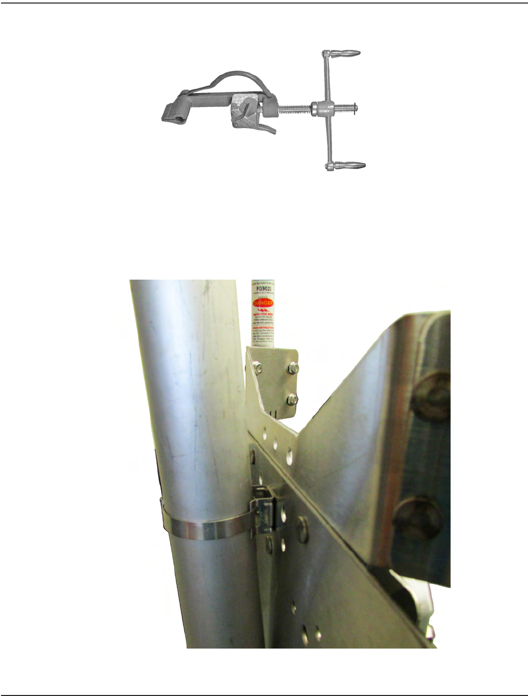
7. Once the antenna mounting bracket is removed,
reattach the enclosure to the mounting backplate.
8. Attach the antenna bracket to the remote mounting
structure using either V-block mounting hardware
or Band-IT banding, depending on the structure.
The example shown in Figure 51 is using V-block
mounting hardware. A side view of the mounting
hardware is shown in Figure 52.
Figure 51: Antenna bracket attached with V-block mounting
hardware
Figure 52: V-block mounting hardware side view
Page 39 October 2013
ORION® SE II Network Gateway Transceiver
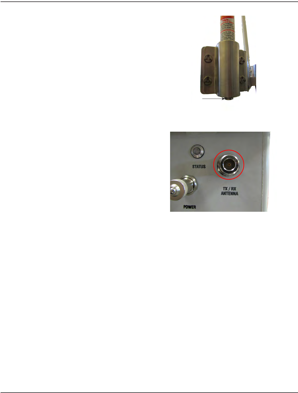
9. Prepare each of the antenna cables and connectors
per manufacturer’s instructions and connect to
the Type N female connector at the bottom of
each antenna.
Tighten each Type N connector to
8…12 inch-pounds. To approximate this
measurement without a torque wrench, nger
tighten the Type N connector and then tighten an
additional 1/16 inch turn with pliers.
OTE:NA lightning arrestor is recommended for
all remote antenna installations. Refer to
"Lightning Arrestors" on page 26 for
additional information.
Figure 53: Type N female connector
10. Collect the required VSWR readings after the
antennas are installed in their nal locations.
Record the information on the form provided by
Badger Meter. Refer to "Required Antenna Tests" on
page 36.
11. After the antenna tests are completed, connect the
TX/RX antenna to the Type N female connector on
the gateway enclosure (marked ”TX/RX Antenna’’).
The antenna cable can be connected directly to the
enclosure. If needed, a 3-foot coaxial cable with
Type N male connectors (PN: 67628-001) can be used
to transition from the antenna connector to the
Type N female connector on the enclosure. Figure 54: TX/RX Antenna connector
12. Loosen the four (4) captive screws on the gateway enclosure cover. Remove the cover, attach the internal backup
battery and reattach the cover. Refer to "Connecting the Battery Backup" on page 9 if you need help.
13. Wire the M12 connector according to the instructions provided and attach the power cable to the gateway enclosure.
14. Mount the gateway enclosure and backplate using V-block mounting hardware or Band-IT banding kit as
appropriate. Refer to "Using the V-block Clamps Mounting Hardware" on page 14 for details.
Type N Female
Connector
Page 40 October 2013
Installation Manual
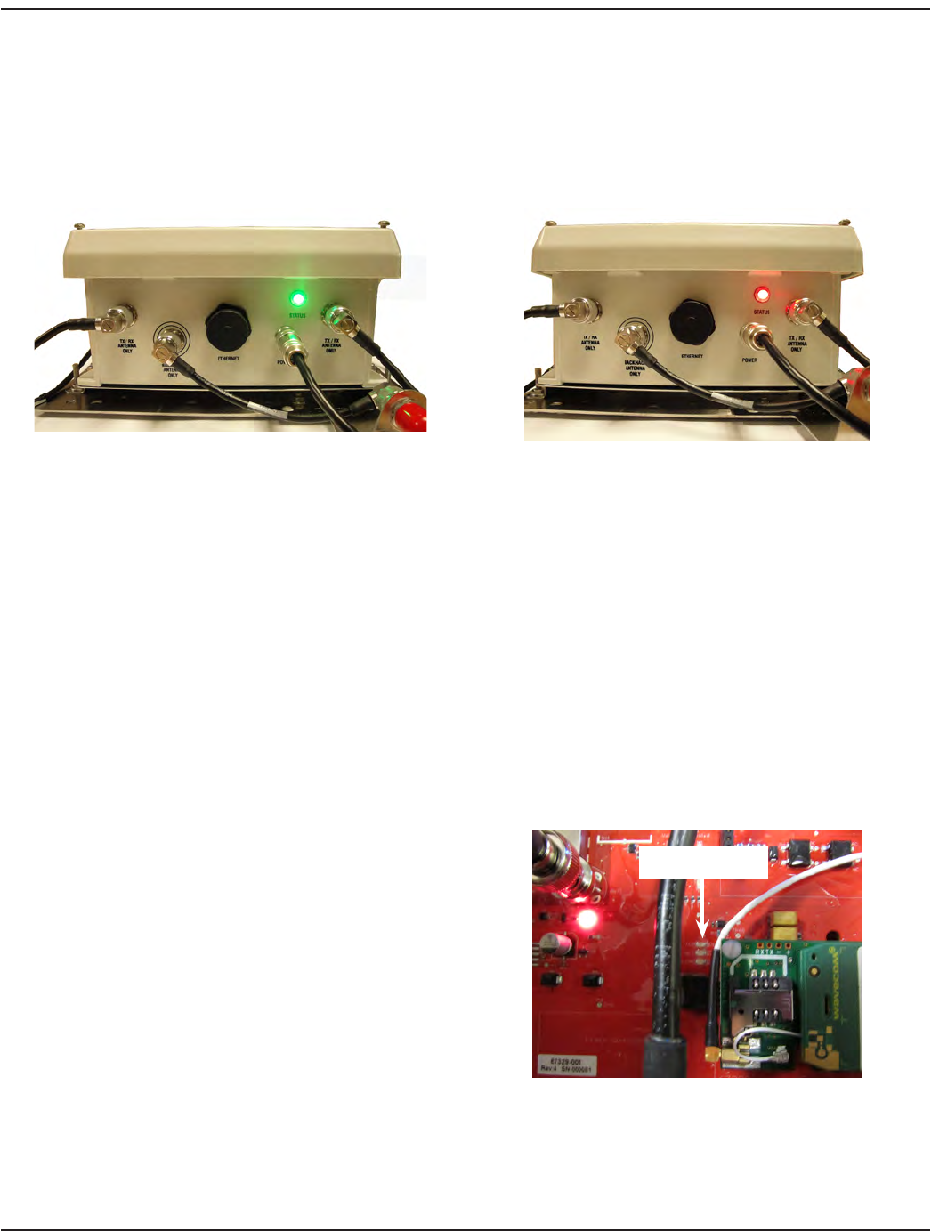
15. Connect the AC adapter and power cord to the gateway power cable using the attached 308 connector and verify
the LED indicator on the bottom of the enclosure is on with a steady green light, indicating the gateway is being AC
powered as shown in Figure 55.
OTE:NA red blinking light indicates the gateway is being powered only by the internal backup battery.
No light indicates the gateway is not receiving AC or backup battery power.
Figure 55: Gateway on AC power Figure 56: Gateway on battery power
16. Complete the ORION SE II Network Gateway Installation Form and send the completed form to Badger Meter with
any attachments. The three-page form starts on page 43.
The remote TX/RX antenna connection is complete.
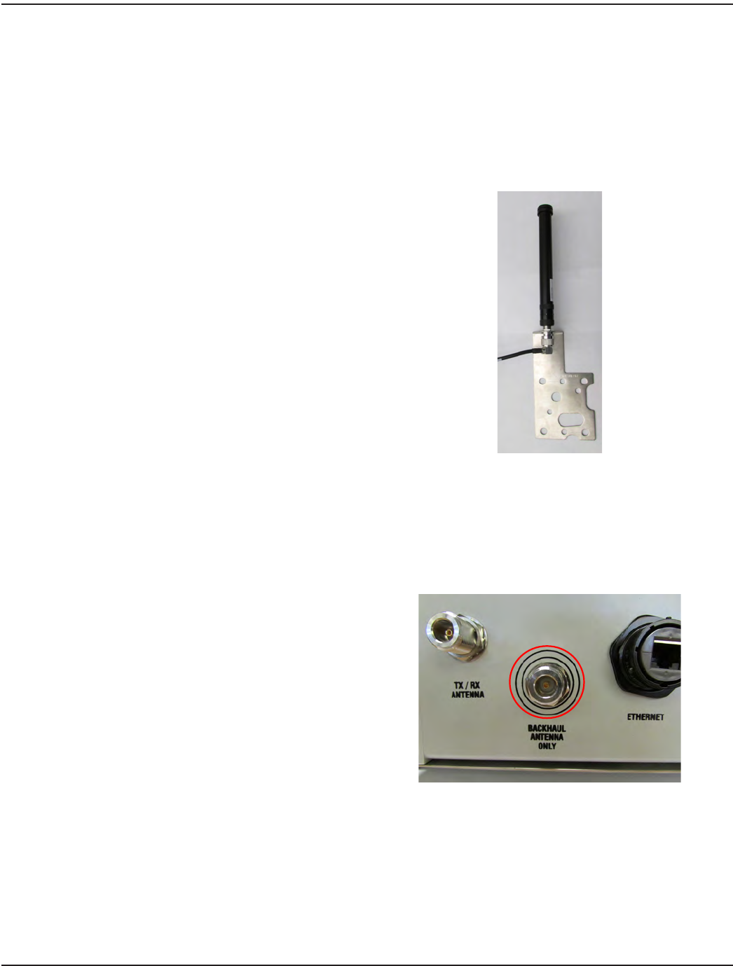
Remote Backhaul Antenna Installation
Before installing the backhaul antenna in a remote location, first determine if a remote installation is needed.
In the location selected for the gateway, test the GPRS backhaul connection while the backhaul antenna is still connected to
the gateway by doing the following.
OTE:NFor testing the backhaul connection, make sure the gateway ReadCenter® Monitor server is running, the enclosure
cover is o the gateway so the circuit board is visible, the backhaul antenna is connected to the gateway and AC
power is available for the gateway.
1. Turn on the gateway AC power. On the circuit board
in the lower left quadrant, next to the SIM card slot,
look for the LED labeled ”TCP“ (Figure 57).
The TCP LED will light when the backhaul links with
the server, signifying a connection.
Figure 57: Backhaul antenna LED
”TCP“ LED
Page 41 October 2013
ORION® SE II Network Gateway Transceiver
2. If there is a connection, the backhaul antenna bracket and antenna can remain connected to the gateway. Remote
installation is not required for the backhaul antenna.
If there is no connection, remove the backhaul antenna bracket from the gateway.
There are two locknuts holding the backhaul antenna mounting bracket on the enclosure backplate. Remove those
to separate the antenna bracket and GPRS antenna from the enclosure backplate.
3. Move the antenna bracket with the GPRS antenna to the nearest outdoor location and test again.
4. If there is a connection, mount the backhaul
antenna bracket.
If there is still no connection to the gateway, move
the antenna bracket and GPRS antenna to the
highest location available, up to 100 feet away from
the gateway enclosure.
5. Mount the backhaul antenna bracket using either
V-block mounting hardware or Band-IT banding,
depending on the structure.
OTE:NThe antenna can be inverted as shown in
Figure 58 for easier mounting.
Figure 58: Inverted backhaul antenna bracket
6. Prepare the cable and connector per manufacturer's instructions and connect to the Type N male connector at the
bottom of the backhaul antenna.
OTE:NA lightning arrestor is recommended for all remote antenna installations. Refer to "Lightning Arrestors" on
page 26 for additional information.
7. Collect the required VSWR readings after the
antenna is installed in its nal location. Record the
information on the form provided by Badger Meter.
Refer to "Required Antenna Tests" on page 36.
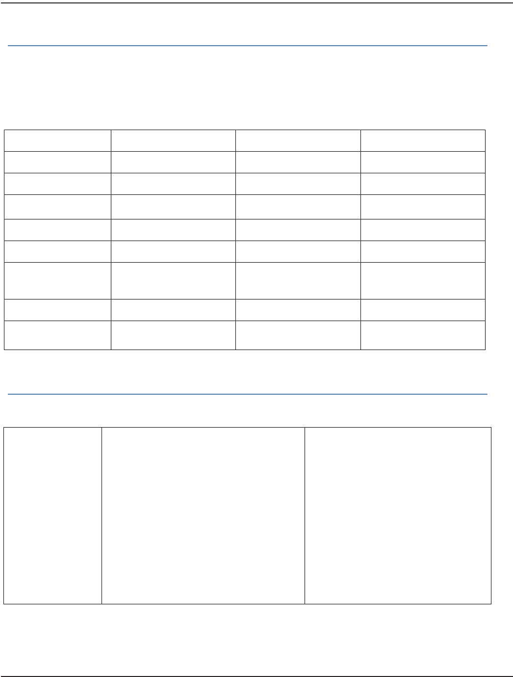
8. Connect the backhaul antenna to the Type N female
connector on the gateway enclosure (marked
”Backhaul Antenna Only”).
The backhaul antenna cable can be connected
directly to the enclosure.
If needed, a 3-foot coaxial cable with Type N male
connectors (PN: 67628-001) can be used to transition
from the backhaul antenna connector to the Type N
female connector on the enclosure.
Figure 59: Backhaul Antenna connector
9. Complete the ORION SE II Network Gateway Installation Form and send the completed form to Badger Meter with
any attachments. The three-page form starts on page 43.
The remote backhaul antenna connection is complete.
Page 42 October 2013

Installation Manual
ORION®SE II Network Gateway
Installation Form
Instructions: Complete a separate form for each gateway installation. Return completed form(s) and attachments
according to the instructions on the last page of the form.
If you have questions about this form, contact Badger Meter Technical Support, TechSupport@BadgerMeter.com or
call 800-876-3837.
ORION SE Network Gateway Transceiver Information
All installations – Complete table below.
Gateway Serial Number
Installation Date
Location
(street address or cross streets)
Gateway Power Source
(location and description)
Mounting Structure
(description of the structure the
transceiver and antenna(s) are
mounted on, including brackets)
Actual Installed Height
(above ground level)
GPS Latitude
GPS Longitude
Location Comments
Page 43 October 2013
ORION® SE II Network Gateway Transceiver
Cables & Connectors
Remote antenna installations only –
Antenna cables and connectors are not included and are to be supplied by the professional installation contractor.
Exact parts specified in Badger Meter installation documentation must be used. Substitutions are not allowed.
Confirm parts used by completing table below.
TX/RX Antenna Left
TX/RX Antenna Right
Backhaul Antenna
Cable Part Number
Cable Length
Connector Part
Number
Flex Cable Kit Used? Yes No Yes No Yes No
VSWR Measurement
Connection
Waterproofing
Method
Grounding Method
Lightning Arrestor
(manufacturer and
model/part number)
Confirmation Photographs
All installations – Photographs of the installation are required as outlined. Confirm photos taken by completing table.
Installation
Pictures
Ground level view of antenna assembly
Antenna cable connections (provide all)
Other antennas in proximity
East-facing line-of-sight from antenna
assembly
West-facing line-of-sight from antenna
assembly
North-facing line-of-sight from antenna
assembly
South-facing line-of-sight from antenna
assembly
Installed gateway enclosure and power
source
Potential obstructions
Lightning arrestor with ground
connections
Other
_________________________________
Other
_________________________________
Other
_________________________________
Badger Meter ORION SE II Network Gateway Installation Form
Page 44 October 2013

Installation Manual
Comments
Installation
Comments
Attach additional
pages as needed
I certify the ORION SE Network Gateway Transceiver and any remote antenna installations, if applicable, have
been completed per Badger Meter documentation and instructions.
Installer Name (print): _____________________________________________________________________________
Title: ___________________________________________________________________________________________
Installation Company: _____________________________________________________________________________
Date: ___________________________________________________________________________________________
Signature: _______________________________________________________________________________________
Instructions for Returning the Form
Return this form and attachments to Badger Meter by one of the following methods.
Email:
TechSupport@BadgerMeter.com
Subject Line: Gateway Installation
Mail:
Badger Meter Inc.
Attn: Gateway Installation
P.O. Box 245036
Milwaukee, WI 53224-9536
Fax:
888-371-5982
Attn: Gateway Installation
Badger Meter ORION SE II Network Gateway Installation Form
Page 45 October 2013

ORION® SE II Network Gateway Transceiver
Page 46 October 2013

Installation Manual
INTENTIONAL BLANK PAGE
Page 47 October 2013

www.badgermeter.com
ORION and ReadCenter are registered trademarks of Badger Meter, Inc. Other trademarks appearing in this document are the property of their respective entities.
Due to continuous research, product improvements and enhancements, Badger Meter reserves the right to change product or system specications without notice, except to the
extent an outstanding contractual obligation exists. © 2013 Badger Meter, Inc. All rights reserved.
The Americas | Badger Meter | 4545 West Brown Deer Rd | PO Box 245036 | Milwaukee, WI 53224-9536 | 800-876-3837 | 414-355-0400
México | Badger Meter de las Americas, S.A. de C.V. | Pedro Luis Ogazón N°32 | Esq. Angelina N°24 | Colonia Guadalupe Inn | CP 01050 | México, DF | México | +52-55-5662-0882
Europe, Middle East and Africa | Badger Meter Europa GmbH | Nurtinger Str 76 | 72639 Neuen | Germany | +49-7025-9208-0
Czech Republic | Badger Meter Czech Republic s.r.o. | Maříkova 2082/26 | 621 00 Brno, Czech Republic | +420-5-41420411
Slovakia | Badger Meter Slovakia s.r.o. | Racianska 109/B | 831 02 Bratislava, Slovakia | +421-2-44 63 83 01
Asia Pacic | Badger Meter | 80 Marine Parade Rd | 21-04 Parkway Parade | Singapore 449269 | +65-63464836
China | Badger Meter | Rm 501, N° 11 Longyue Apartment | N° 180 Longjin Rd, Jiuting Songjiang District | Shanghai, China | 201615 | +86-21-5763 5412