Badger Meter BADGERAM Orion Gas Transmitter User Manual Exhibit D Users Manual per 2 1033 b3
Badger Meter Inc Orion Gas Transmitter Exhibit D Users Manual per 2 1033 b3
Exhibit D Users Manual per 2 1033 b3

Installation &
Operation Manual
BadgerMeter, Inc.
®
ORI-IOM-39
P/N 62014-062 Rev. 2
5-06
ORION®
Automated Meter
Reading System
ORION Integral Transmitter
for Gas Meters
IMPORTANT: This manual contains important warnings and information.
READ AND KEEP FOR REFERENCE.
Sensus®/Rockwell®/Equimeter®
Gas Meters American®
Gas Meter
Actaris® Slope Face
Gas Meter Actaris® Straight Face
Gas Meter

2
Disclaimer
The user/purchaser is expected to read and understand the information provided in this manual,
follow any listed Safety Precautions and Instructions and keep this manual with the equipment for
future reference.
Misuse, mishandling and/or inadequate maintenance may impair performance and/or compromise
safety.
Questions or Service Assistance
If you have questions regarding the product or this document contact:
Badger Meter, Incorporated
P.O. Box 245036
Milwaukee, WI 53224-9536
Telephone: (414) 355-0400, (800) 876-3837
Fax: (888) 371-5982
On the Web: www.badgermeter.com
or call your local Badger Meter representative.
Product Identification Information
Record the product identification numbers from the nameplate.
Transmitter
Model Number _ ______
Serial Number _____________
Tag Number _______________
3
Table of Contents
Disclaimer ................................................................................................................................. 2
Questions or Service Assistance ................................................................................................ 2
Product Identification Information ...............................................................................................2
Note Explanations ...................................................................................................................... 4
SCOPE OF MANUAL ................................................................................................................4
PRODUCT UNPACKING AND INSPECTION ........................................................................... 4
License Requirements ...............................................................................................................4
ORION® Integral Transmitters/Hardcase Gas Meters Identification ............................................ 5
Installation Tools and Materials .................................................................................................. 5
Label Information ........................................................................................................................ 5
Installation of ORION Integral Transmitter .................................................................................. 5
SENSUS®/ROCKWELL®/EQUIMETER® MODELS R-175/200/250/275 (11 TOOTH)
With Dial or Odometer Index ...................................................................................................... 7
Before Starting Installation ......................................................................................................... 7
Index Removal From Rockwell Meter.........................................................................................7
Install ORION Transmitter and Sensus Index on Meter .............................................................. 8
Program the ORION Transmitter ..............................................................................................10
Complete the Installation .......................................................................................................... 10
AMERICAN® MODELS AL-175/250/425/630 With Dial or Odometer Index ............................11
Before Starting Installation Meter .............................................................................................11
Index Removal From American Meter ......................................................................................11
Install ORION Transmitter and American Index on Meter .........................................................12
Program the ORION Transmitter ..............................................................................................12
Complete the Installation .......................................................................................................... 13
ACTARIS® SLOPE FACE MODELS 175/250/400 With Dial or Odometer Index .................... 15
Before Starting Installation ....................................................................................................... 15
Index Removal From Actaris Slope Face Meter .......................................................................16
Install ORION Transmitter and Actaris Index on Slope Face Meter .......................................... 16
Program the ORION Transmitter ..............................................................................................17
Complete the Installation .......................................................................................................... 18
ACTARIS® STRAIGHT FACE MODELS 175/250/400 With Odometer Index..........................19
Before Starting Installation ....................................................................................................... 19
Index Removal From Actaris Straight Face Meter .................................................................... 20
Install ORION Transmitter and Index on Actaris Straight Face Meter .......................................20
Program the ORION Transmitter ..............................................................................................21
Complete the Installation .......................................................................................................... 22
4
License Requirements
This device complies with Part 15 of FCC
Rules. Operation of this device is subject to
the following conditions: (1) This device may
not cause harmful interference, and (2) this
device must accept any interference received,
including interference that may cause
undesired operation.
No FCC license is required by a utility to
operate an ORION meter reading system.
Any changes made, but not approved by
Badger Meter, can void the user’s authority to
operate the equipment.
Note Explanations
NOTE:
Communicates installation, operation or
maintenance information that is safety related but
not hazard related.
SCOPE of MANUAL
This manual contains installation instructions
for the ORION® Integral Transmitter for Gas
Meters.
Proper performance and reliability of the
ORION gas meter system depends upon
installation in accordance with these
instructions.
PRODUCT UNPACKING AND
INSPECTION
Upon receipt of the product, perform the
following unpacking and inspection
procedures:
NOTE:
If damage to the shipping container is
evident upon receipt, request the carrier to be
present when the product is unpacked.
Carefully open the shipping package, follow
any instructions that may be marked on the
exterior. Remove all cushioning material
surrounding the product and carefully lift the
product from the package.
Retain the package and all packing material
for possible use in reshipment or storage.
Visually inspect the product and applicable
accessories for any physical damage such as
scratches, loose or broken parts, or any other
sign of damage that may have occurred
during shipment.
NOTE:
If damage is found, request an inspection
by the carrier’s agent within 48 hours of delivery
and file a claim with the carrier. A claim for
equipment damage in transit is the sole
responsibility of the purchaser.
5
ORION® Integral Transmitters/Hardcase
Gas Meter Identification
ORION integral transmitters for gas meters
are designed for use with a variety of major
brands of hardcase gas meters. Please refer
to and use the following identification table.
Identification Table
Installation of ORION Integral Transmitter
This manual describes installing the ORION
transmitter and index on Sensus, American,
and Actaris gas meters.
ORION®
Gas Meter Manufacturer Gas Meter Model Transmitter #
Sensus®/Invensys®/ R-175/200/250/275
Rockwell®/Equimeter® Meters 11 tooth 64989-001
American® Meter AL-175/250/425/630 64989-002
Actaris® Slope Face Meter 175/250/400 64989-003
Actaris® Straight Face Meter 175/250/400 64989-004
Installation Tools and Materials
Use magnetized screwdrivers.
1/8" flat screwdriver
¼” flat screwdriver
#1 Phillips screwdriver
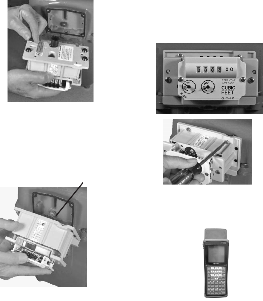
Radix® Hand Held
or
Optical Programming Probe and Laptop
computer
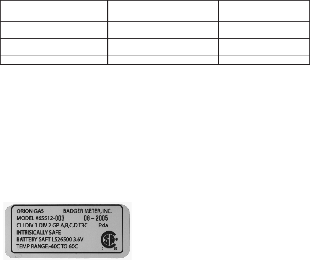
Label Information
Certification markings are noted on the
product label. Label markings include:
Model number 65512-003 08-2005
are completed with proper numbers printed at
003 08-2005.
Battery SAFT LS26500 is a 3.6V Lithium C
cell.
Battery SAFT LSI7500 is a 3.6V Lithium A
cell.

6
(This page intentionally left blank)

7
SENSUS®/ROCKWELL®/EQUIMETER® MODELS R-175/200/250/275 11 Tooth
With Dial or Odometer Index
Gas Meter Mfgr Gas Meter Model ORION® Transmitter #
Sensus/Invensys®/
Rockwell/Equimeter Meters R-175/200/250/275 11 tooth 64989-001
Index Removal From Sensus Meter
Step 1: Use a screwdriver to puncture and
remove tamper plugs, if present.
Step 2: Use a screwdriver to remove and
discard the four (4) cover mounting screws
and the cover.
Before proceeding with an installation, make
sure the ORION transmitter name matches the
model required for the specific gas meter.
Transmitter
Name
Gasket
4 Plugs
Transmitter
4 Screws
2 Stand Offs
Index
2 Phillips Screws
Gasket
Cover
2 Screws
2 Tamper Plugs
ORION® for Sensus Transmitter Kit
(Not part of kit)
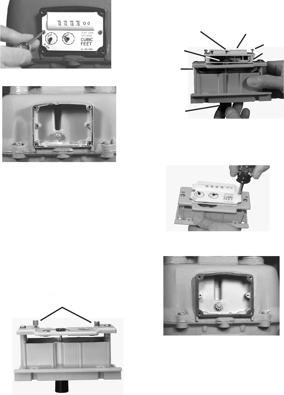
Before Starting Installation
Remove the two screws holding the
cover onto the transmitter.
Place a screwdriver in a
hole in the rear of the
transmitter and gently
break the cover and
gasket from the
transmitter.
Sensus Gas Meter and Indexes
8
2 foot dial
Transmitter
Moving the
two foot dials
Index on XMTR
Step 3: Secure the index to the transmitter
with the two (2) supplied Phillips screws
placed in the stand offs.
Step 4: Mount the gasket to the meter.
Step 4: Remove and discard old gasket.
Step 3: Use a screwdriver to remove and
discard the two (2) index mounting screws.
Install ORION® Transmitter and Sensus
Index on Meter
Use care when handling the ORION
transmitter to insure the drive pawl is not
subjected to any physical abuse. Abuse may
cause this spindle to become bent,
misaligned or otherwise inoperative.
When attaching a meter index to an ORION
transmitter, make sure it mounts securely. The
two drive gears must mate without causing
any binding or potential for disengagement.
Step 1: Place the two (2) supplied stand offs
in the transmitter.
Stand Offs
Step 2: Place the index on the front of the
ORION transmitter.
Line up two front gears. Test to ensure the
gears are engaged and moving freely by
moving the 2 foot dial.
2 Screws
2 Stand Offs
2 foot dial
Gears aligned
Transmitter
Moving the
two foot dial
9
Program the ORION Transmitter
Badger Meter uses the Badger®-Radix®
system to display and process screens.
Please reference the document “Instructions
for Installing ORION Gas Meters Using the
Radix Programming Tool”.
The meter is now installed. On the Badger-
Radix you’ll see the next meter number and
the process starts again.
Step 5: Care must be taken when placing a
transmitter/index unit on the meter.
Before placing the transmitter/index on the
gas meter put four (4) supplied plugs into the
rear of the transmitter.
Step 7: There is some adjustment in the
position of the index plate. Make sure the
index is positioned so the shaft turns freely
about ½ turn.
Step 6: When mounting an ORION®
transmitter to a gas meter, make sure the gas
meter drive gear engages the transmitter drive
pawl. These two drive pawls must mate
without causing any binding or potential for
disengagement.
Drive Gear
Drive Pawl
Step 8: There are three (3) different lengths
of mounting screws in the transmitter kit.
Install the shortest screw in the top left (#1)
of the ORION transmitter.
Install the second longest screw in the top
right (#2).
Install the two (2) longest screws in the
bottom (#3 and #4).
3 4
1 2

10
Installation of ORION for SENSUS® MODEL
R-175/200/250/275 (11 Tooth) with dial or
odometer index is now complete.
Step 3: For security purposes, insert the two
(2) supplied red tamper plugs over the screws
and push them in.
Step 2: Install the cover with the two (2)
supplied screws.
Complete the Installation
Step 1: Place the ORION® cover over the
outside of the index and transmitter.