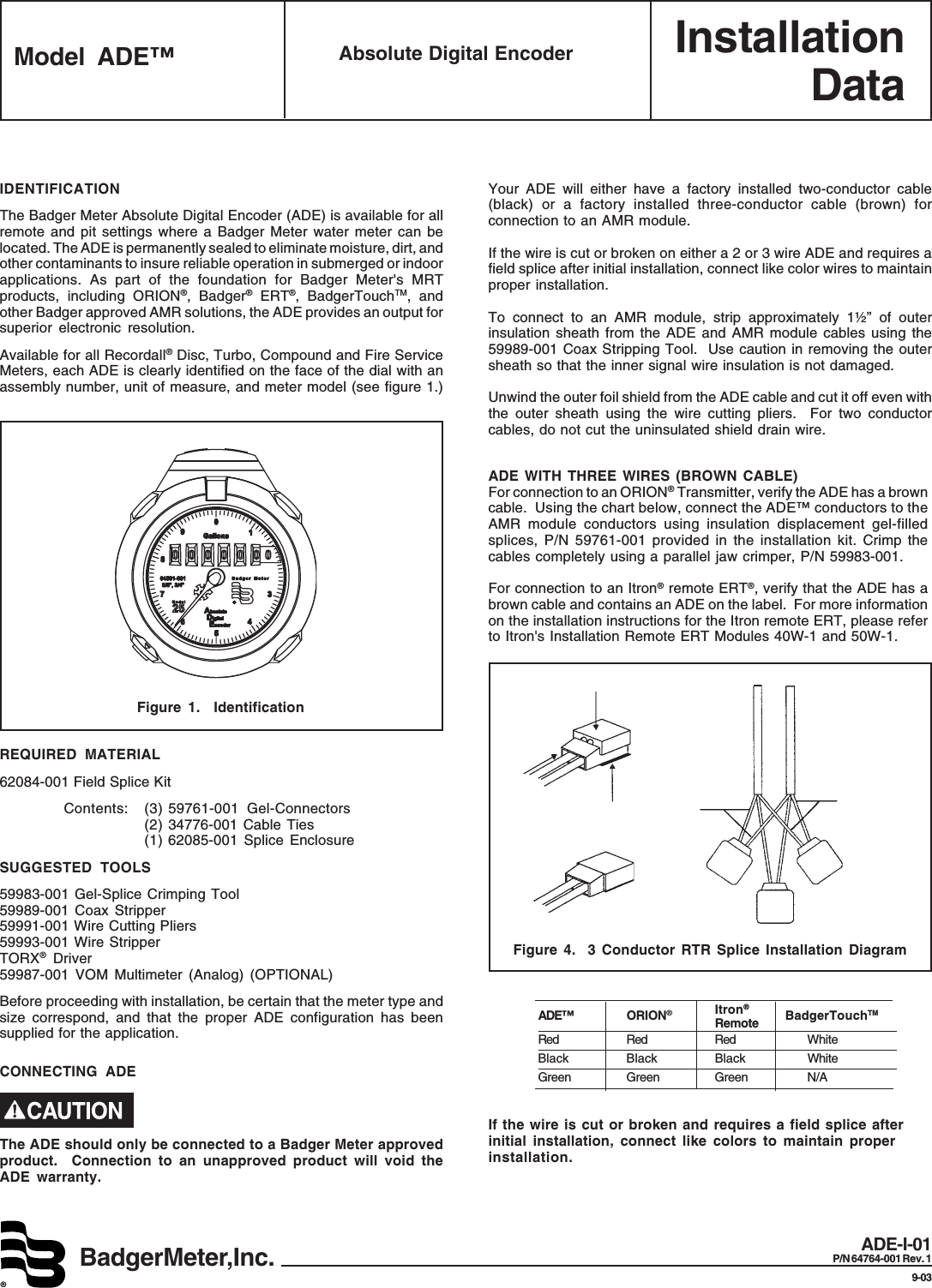
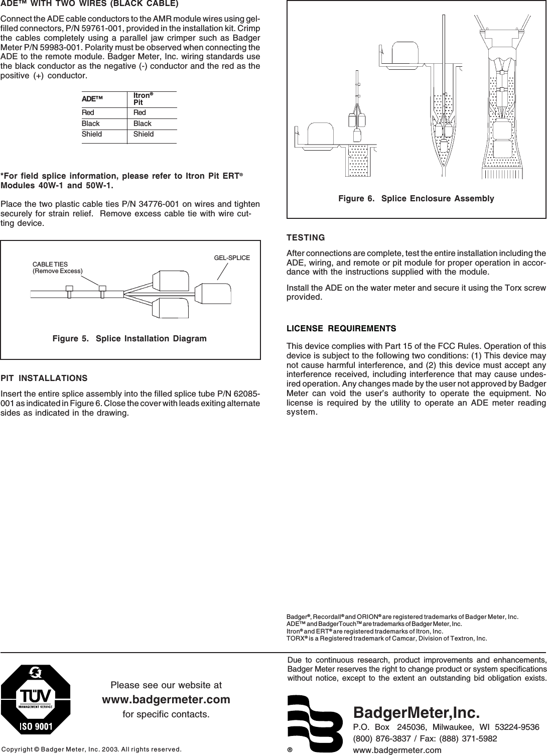
Badger Meter BTOUCH BadgerTouch or ADE User Manual ADE Installation Data Sheet pmd

Badger Meter Inc BadgerTouch or ADE ADE Installation Data Sheet pmd

Exhibit D Users Manual per 2 1033 b3

InstallationDataBadgerMeter,Inc.®Model ADE™ Absolute Digital EncoderADE-I-01P/N 64764-001 Rev. 19-03IDENTIFICATIONThe Badger Meter Absolute Digital Encoder (ADE) is available for allremote and pit settings where a Badger Meter water meter can belocated. The ADE is permanently sealed to eliminate moisture, dirt, andother contaminants to insure reliable operation in submerged or indoorapplications. As part of the foundation for Badger Meter's MRTproducts, including ORION®, Badger® ERT®, BadgerTouchTM, andother Badger approved AMR solutions, the ADE provides an output forsuperior electronic resolution.Available for all Recordall® Disc, Turbo, Compound and Fire ServiceMeters, each ADE is clearly identified on the face of the dial with anassembly number, unit of measure, and meter model (see figure 1.)SUGGESTED TOOLS59983-001 Gel-Splice Crimping Tool59989-001 Coax Stripper59991-001 Wire Cutting Pliers59993-001 Wire StripperTORX® Driver59987-001 VOM Multimeter (Analog) (OPTIONAL)Before proceeding with installation, be certain that the meter type andsize correspond, and that the proper ADE configuration has beensupplied for the application.REQUIRED MATERIAL62084-001 Field Splice KitContents: (3) 59761-001 Gel-Connectors(2) 34776-001 Cable Ties(1) 62085-001 Splice EnclosureFigure 1.  IdentificationCONNECTING ADEThe ADE should only be connected to a Badger Meter approvedproduct.  Connection to an unapproved product will void theADE warranty.Your ADE will either have a factory installed two-conductor cable(black) or a factory installed three-conductor cable (brown) forconnection to an AMR module.If the wire is cut or broken on either a 2 or 3 wire ADE and requires afield splice after initial installation, connect like color wires to maintainproper installation.To connect to an AMR module, strip approximately 1½” of outerinsulation sheath from the ADE and AMR module cables using the59989-001 Coax Stripping Tool.  Use caution in removing the outersheath so that the inner signal wire insulation is not damaged.Unwind the outer foil shield from the ADE cable and cut it off even withthe outer sheath using the wire cutting pliers.  For two conductorcables, do not cut the uninsulated shield drain wire.ADE WITH THREE WIRES (BROWN CABLE)For connection to an ORION® Transmitter, verify the ADE has a browncable.  Using the chart below, connect the ADE™ conductors to theAMR module conductors using insulation displacement gel-filledsplices, P/N 59761-001 provided in the installation kit. Crimp thecables completely using a parallel jaw crimper, P/N 59983-001.For connection to an Itron® remote ERT®, verify that the ADE has abrown cable and contains an ADE on the label.  For more informationon the installation instructions for the Itron remote ERT, please referto Itron's Installation Remote ERT Modules 40W-1 and 50W-1.Figure 4.  3 Conductor RTR Splice Installation DiagramIf the wire is cut or broken and requires a field splice afterinitial installation, connect like colors to maintain properinstallation.ADE™ ORION®Itron®                                 BadgerTouchTMRemoteRed Red Red WhiteBlack Black Black WhiteGreen Green Green N/A
®Due to continuous research, product improvements and enhancements,Badger Meter reserves the right to change product or system specificationswithout notice, except to the extent an outstanding bid obligation exists.Copyright © Badger Meter, Inc. 2003. All rights reserved.Please see our website atwww.badgermeter.comfor specific contacts. BadgerMeter,Inc.P.O.  Box   245036,  Milwaukee,  WI  53224-9536(800) 876-3837 / Fax: (888) 371-5982www.badgermeter.comBadger®, Recordall® and ORION® are registered trademarks of Badger Meter, Inc.ADE™ and BadgerTouchTM are trademarks of Badger Meter, Inc.Itron® and ERT® are registered trademarks of Itron, Inc.TORX® is a Registered trademark of Camcar, Division of Textron, Inc.PIT INSTALLATIONSInsert the entire splice assembly into the filled splice tube P/N 62085-001 as indicated in Figure 6. Close the cover with leads exiting alternatesides as indicated in the drawing.TESTINGAfter connections are complete, test the entire installation including theADE, wiring, and remote or pit module for proper operation in accor-dance with the instructions supplied with the module.Install the ADE on the water meter and secure it using the Torx screwprovided.LICENSE REQUIREMENTSThis device complies with Part 15 of the FCC Rules. Operation of thisdevice is subject to the following two conditions: (1) This device maynot cause harmful interference, and (2) this device must accept anyinterference received, including interference that may cause undes-ired operation. Any changes made by the user not approved by BadgerMeter can void the user’s authority to operate the equipment. Nolicense is required by the utility to operate an ADE meter readingsystem.CABLE TIES(Remove Excess)GEL-SPLICEFigure 5.  Splice Installation DiagramADE™ WITH TWO WIRES (BLACK CABLE)Connect the ADE cable conductors to the AMR module wires using gel-filled connectors, P/N 59761-001, provided in the installation kit. Crimpthe cables completely using a parallel jaw crimper such as BadgerMeter P/N 59983-001. Polarity must be observed when connecting theADE to the remote module. Badger Meter, Inc. wiring standards usethe black conductor as the negative (-) conductor and the red as thepositive (+) conductor.*For field splice information, please refer to Itron Pit ERT®Modules 40W-1 and 50W-1.Place the two plastic cable ties P/N 34776-001 on wires and tightensecurely for strain relief.  Remove excess cable tie with wire cut-ting device.Figure 6.  Splice Enclosure AssemblyADE™ Itron®PitRed RedBlack BlackShield Shield

Navigation menu