Badger Meter BTOUCH BadgerTouch or ADE User Manual ADE Installation Data Sheet pmd
Badger Meter Inc BadgerTouch or ADE ADE Installation Data Sheet pmd
Exhibit D Users Manual per 2 1033 b3
Installation
Data
BadgerMeter,Inc.
®
Model ADE™ Absolute Digital Encoder
ADE-I-01
P/N 64764-001 Rev. 1
9-03
IDENTIFICATION
The Badger Meter Absolute Digital Encoder (ADE) is available for all
remote and pit settings where a Badger Meter water meter can be
located. The ADE is permanently sealed to eliminate moisture, dirt, and
other contaminants to insure reliable operation in submerged or indoor
applications. As part of the foundation for Badger Meter's MRT
products, including ORION®, Badger® ERT®, BadgerTouchTM, and
other Badger approved AMR solutions, the ADE provides an output for
superior electronic resolution.
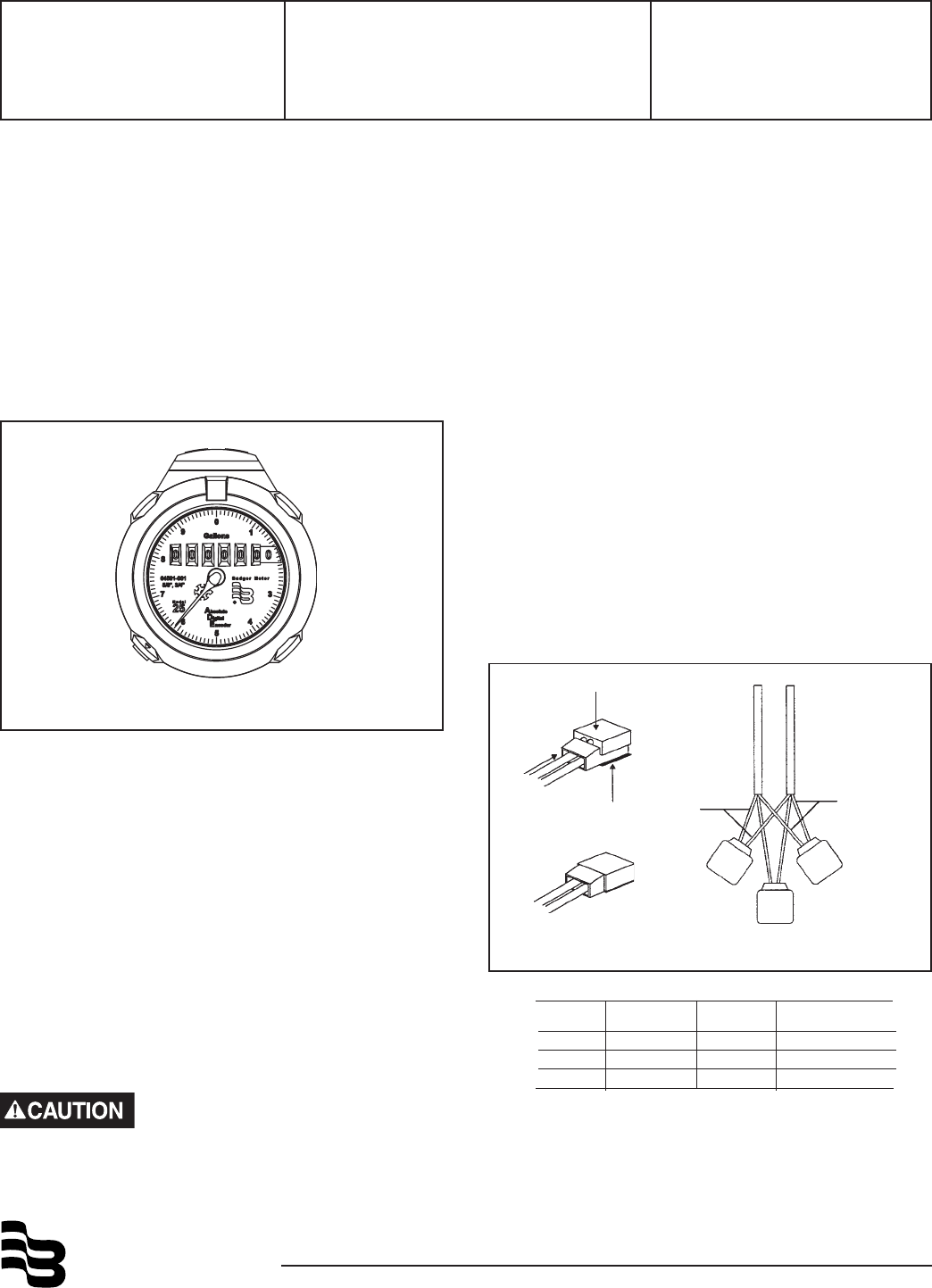
Available for all Recordall® Disc, Turbo, Compound and Fire Service
Meters, each ADE is clearly identified on the face of the dial with an
assembly number, unit of measure, and meter model (see figure 1.)
SUGGESTED TOOLS
59983-001 Gel-Splice Crimping Tool
59989-001 Coax Stripper
59991-001 Wire Cutting Pliers
59993-001 Wire Stripper
TORX® Driver
59987-001 VOM Multimeter (Analog) (OPTIONAL)
Before proceeding with installation, be certain that the meter type and
size correspond, and that the proper ADE configuration has been
supplied for the application.
REQUIRED MATERIAL
62084-001 Field Splice Kit
Contents: (3) 59761-001 Gel-Connectors
(2) 34776-001 Cable Ties
(1) 62085-001 Splice Enclosure
Figure 1. Identification
CONNECTING ADE
The ADE should only be connected to a Badger Meter approved
product. Connection to an unapproved product will void the
ADE warranty.
Your ADE will either have a factory installed two-conductor cable
(black) or a factory installed three-conductor cable (brown) for
connection to an AMR module.
If the wire is cut or broken on either a 2 or 3 wire ADE and requires a
field splice after initial installation, connect like color wires to maintain
proper installation.
To connect to an AMR module, strip approximately 1½” of outer
insulation sheath from the ADE and AMR module cables using the
59989-001 Coax Stripping Tool. Use caution in removing the outer
sheath so that the inner signal wire insulation is not damaged.
Unwind the outer foil shield from the ADE cable and cut it off even with
the outer sheath using the wire cutting pliers. For two conductor
cables, do not cut the uninsulated shield drain wire.
ADE WITH THREE WIRES (BROWN CABLE)
For connection to an ORION® Transmitter, verify the ADE has a brown
cable. Using the chart below, connect the ADE™ conductors to the
AMR module conductors using insulation displacement gel-filled
splices, P/N 59761-001 provided in the installation kit. Crimp the
cables completely using a parallel jaw crimper, P/N 59983-001.
For connection to an Itron® remote ERT®, verify that the ADE has a
brown cable and contains an ADE on the label. For more information
on the installation instructions for the Itron remote ERT, please refer
to Itron's Installation Remote ERT Modules 40W-1 and 50W-1.
Figure 4. 3 Conductor RTR Splice Installation Diagram
If the wire is cut or broken and requires a field splice after
initial installation, connect like colors to maintain proper
installation.
ADE™ ORION®Itron® BadgerTouchTM
Remote
Red Red Red White
Black Black Black White
Green Green Green N/A
®
Due to continuous research, product improvements and enhancements,
Badger Meter reserves the right to change product or system specifications
without notice, except to the extent an outstanding bid obligation exists.
Copyright © Badger Meter, Inc. 2003. All rights reserved.
Please see our website at
www.badgermeter.com
for specific contacts. BadgerMeter,Inc.
P.O. Box 245036, Milwaukee, WI 53224-9536
(800) 876-3837 / Fax: (888) 371-5982
www.badgermeter.com
Badger®, Recordall® and ORION® are registered trademarks of Badger Meter, Inc.
ADE™ and BadgerTouchTM are trademarks of Badger Meter, Inc.
Itron® and ERT® are registered trademarks of Itron, Inc.
TORX® is a Registered trademark of Camcar, Division of Textron, Inc.
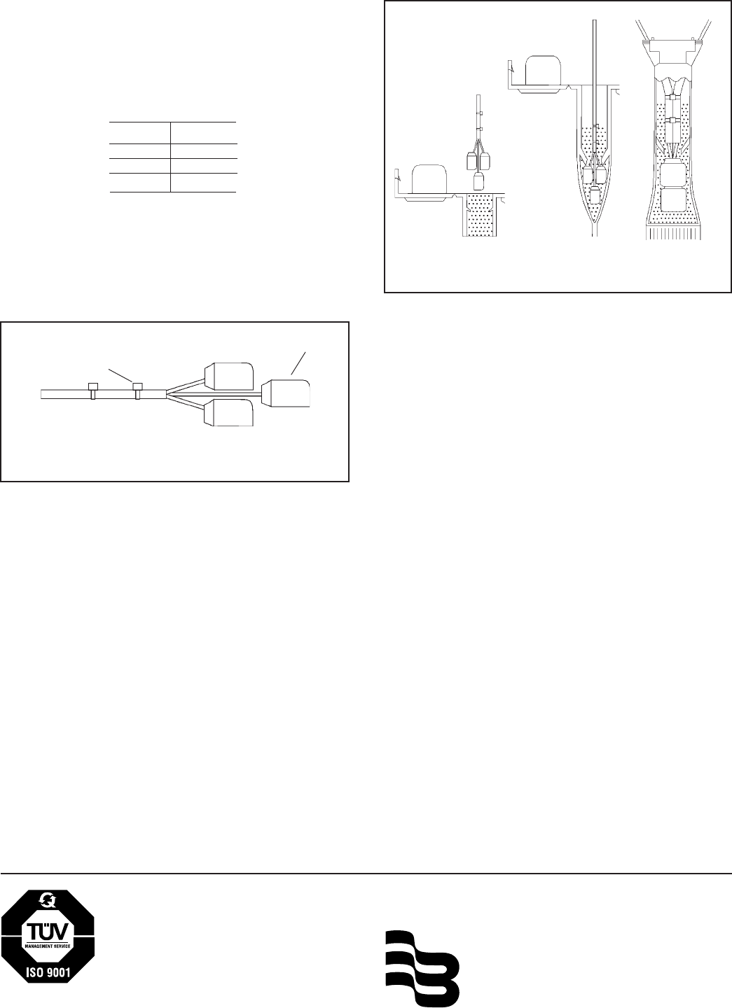
PIT INSTALLATIONS
Insert the entire splice assembly into the filled splice tube P/N 62085-
001 as indicated in Figure 6. Close the cover with leads exiting alternate
sides as indicated in the drawing.
TESTING
After connections are complete, test the entire installation including the
ADE, wiring, and remote or pit module for proper operation in accor-
dance with the instructions supplied with the module.
Install the ADE on the water meter and secure it using the Torx screw
provided.
LICENSE REQUIREMENTS
This device complies with Part 15 of the FCC Rules. Operation of this
device is subject to the following two conditions: (1) This device may
not cause harmful interference, and (2) this device must accept any
interference received, including interference that may cause undes-
ired operation. Any changes made by the user not approved by Badger
Meter can void the user’s authority to operate the equipment. No
license is required by the utility to operate an ADE meter reading
system.
CABLE TIES
(Remove Excess)
GEL-SPLICE
Figure 5. Splice Installation Diagram
ADE™ WITH TWO WIRES (BLACK CABLE)
Connect the ADE cable conductors to the AMR module wires using gel-
filled connectors, P/N 59761-001, provided in the installation kit. Crimp
the cables completely using a parallel jaw crimper such as Badger
Meter P/N 59983-001. Polarity must be observed when connecting the
ADE to the remote module. Badger Meter, Inc. wiring standards use
the black conductor as the negative (-) conductor and the red as the
positive (+) conductor.
*For field splice information, please refer to Itron Pit ERT®
Modules 40W-1 and 50W-1.
Place the two plastic cable ties P/N 34776-001 on wires and tighten
securely for strain relief. Remove excess cable tie with wire cut-
ting device.
Figure 6. Splice Enclosure Assembly
ADE™ Itron®
Pit
Red Red
Black Black
Shield Shield