Baicells Technologies EG7035 LTE Outdoor CPE User Manual BaiCells EG7035
Baicells Technologies Co., Ltd. LTE Outdoor CPE BaiCells EG7035
Users Manual

All rights reserved © BaiCells Technologies Co., Ltd.
BaiCells EG7035 User Manual
V1.0
1
About This Document
This document introduces the specifications of BaiCells EG7035 CPE and guides users to
install and configure it.
Copyright Notice
BaiCells copyrights this specification. No part of this specification may be reproduced in
any form or means, without the prior written consent of BaiCells.
Disclaimer
This specification is preliminary and is subject to change at any time without notice.
BaiCells assumes no responsibility for any errors contained herein. For more information,
please consult our technical engineers.
Revision Record
Date
Version
Description
Author
15 Jun,2015
V1.0
Initial released.
Tang Houcheng
Contact Us
E-mail: support@baicells.com
Phone: 86-10-62607100
Website: http://www.baicells.com/

Contents
1. Product Overview ....................................................................................................... 1
Introduction .............................................................................................................. 1 1.1
Features ..................................................................................................................... 1 1.2
Product Description.................................................................................................... 2 1.3
Appearance ............................................................................................................... 2 1.4
Interface and Button ................................................................................................ 3 1.5
LED Indicators ........................................................................................................... 3 1.6
2. Technical Specifications ............................................................................................... 4
Basic Specification .................................................................................................... 4 2.1
RF Specification ........................................................................................................ 4 2.2
SW Specification ....................................................................................................... 4 2.3
Device Management .................................................................................................. 5 2.4
Environment Specification ......................................................................................... 5 2.5
Regulatory Compliance .............................................................................................. 6 2.6
3. Product Installation ....................................................................................................... 8
1.1 Installation Steps ............................................................................................................. 8
4. CPE Configuration ....................................................................................................... 9
Log in .......................................................................................................................... 9 4.1
Basic Configuration .................................................................................................... 9 4.2
Network Mode .................................................................................................... 9 4.2.1
LTE Setting ........................................................................................................ 10 4.2.2
Setting Connect Method .................................................................................. 11 4.2.3
Manual Connect Network ................................................................................ 11 4.2.4
Setting Scan Mode ............................................................................................ 12 4.2.5
Setting Frequency (Earfcn) ............................................................................... 12 4.2.6
APN Management ............................................................................................ 13 4.2.7
FAQs ......................................................................................................... 14 Appendix A

2
A.1 The POWER indicator does not turn on. .................................................................. 14
A.2 Fails to Login to the web management page. .......................................................... 14
A.3 The CPE fails to search for the wireless network. .................................................... 14
A.4 The power adapter of the CPE is overheated. ......................................................... 14
A.5 The parameters are restored to default values. ...................................................... 14
Product List .............................................................................................. 15 Appendix B

Contents of Figure
Figure 1-1 EG7035 Appearance .................................................................................. 2
Figure 1-2 Interface and Button of EG7035 ................................................................. 3
Figure 3-1 Install the Sample .......................................................................................... 8
Figure 3-2 Connection Diagram ...................................................................................... 8
Figure 4-1 Login Page .................................................................................................. 9
Figure 4-2 Setup Network Mod .................................................................................. 10
Figure 4-3 LTE Setting ................................................................................................ 10
Figure 4-4 Setup Connect Method ............................................................................. 11
Figure 4-5 Setup Scan Mode ..................................................................................... 12
Figure 4-6 Setting frequency ...................................................................................... 13
Figure 4-7 APN Management ..................................................................................... 13

Contents of Table
Table 1-1 EG7035 Product Description ........................................................................ 2
Table 1-2 EG7035 Appearance Index .......................................................................... 2
Table 1-3 Description of EG7035 Interface and Button ............................................... 3
Table 1-4 LED Indicators .............................................................................................. 3
Table 2-1 Basic Specification ....................................................................................... 4
Table 2-2 RF Specification ........................................................................................... 4
Table 2-3 SW Specification .......................................................................................... 4
Table 2-4 Device Management..................................................................................... 5
Table 2-5 Environment Specification ............................................................................ 6

1
1. Product Overview
Introduction 1.1
Baicells is a high-tech company dedicated in wireless broadband access solutions and
service operation. With the advent of the Internet+ era, the development of WBB is
imminent. Through continuous innovation, Baicells launches the world first mobile
broadband system based on the Internet architecture and unlicensed spectrum.
Baicells can provide serious CPEs, include indoor and outdoor unit on different
spectrums.
Baicells EG7035 is a high performance outdoor CPE. EG7035 has the superior
wireless access performance and comprehensive routing capabilities, which have the
abilities to bring the end-users WBB services.
Features 1.2
EG7035 is designed according to the simplicity principle, which can evolve in a short
period and realize fast customization, delivery and deployment as well. The main
features of EG7035 is as follows:
Support TD-LTE network according to the operator’s choice.
LTE comply to 3GPP Release9 CAT4.
LTE TDD 3650MHz - 3700MHz
Support the 100Mbps Ethernet WAN.
Intuitionist and convenient Web-based management.
Built-in LTE bipolar directional high gain antenna.
Support TR069 and OMA-DM network management protocol.
Support Cell lock. SIM lock. Pin lock.
User-friendly design of LED indicator.
Power supply with PoE.
2
Protection support IP67.
Support pole installation or wall mounting.
Product Description 1.3
EG7035 CPE product is shown in Table 1-1.
Table 1-1 EG7035 Product Description
Product
Description
EG7035
3.65G LTE Customer Premise Equipment
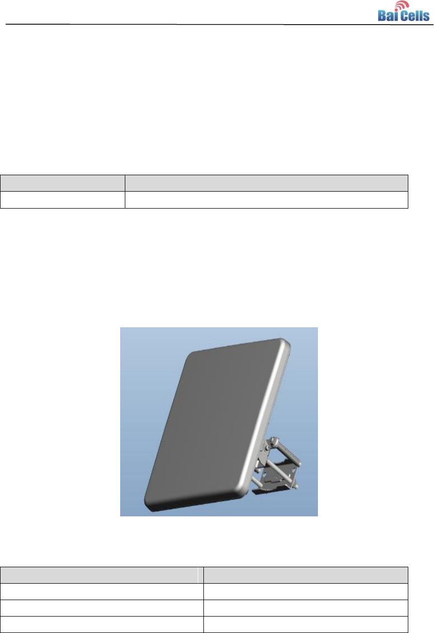
Appearance 1.4
The appearance of EG7035 is shown in Figure 1-1, and is described in Table 1-2.
Figure 1-1 EG7035 Appearance
Table 1-2 EG7035 Appearance Index
Index
Description
Dimension
About 280mm * 280mm * 135mm
Weight
About 1000g
Color
French grey
3
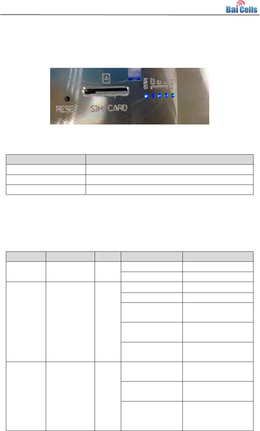
Interface and Button 1.5
The interface of EG7035 is shown in Figure 1-2, and is described in Table 1-3.
Figure 1-2 Interface and Button of EG7035
Table 1-3 Description of EG7035 Interface and Button
Connectors
Description
ETH RJ45
One LAN
USIM Slot
Support 1.8V/3.0V USIM
Restore Button
Long press over 10s to restore the factory settings
LED Indicators 1.6
Table 1-4 LED Indicators
LED Name
Description
Color
LED Behavior
Status Indicator
PWR
Power
Indicator
Green
OFF
No Power Supply
Steady On
Power On
LTE Signal
3 LTEs,
Indicate
connection
state and
signal
strength
Green
All OFF
No Connected
ALL blanking
Connecting
One LED Steady
On
Connected, the
signal is weak
Two LED Steady
On
Connected, the
signal is medium
Three LED Steady
On
Connected, the
signal is strong
LAN
Eth Indication
Green
OFF
Ethernet connection
is not established
Steady On
Ethernet connection
is normal
Blanking
Ethernet interface
data being
transmitted
4
2. Technical Specifications
Basic Specification 2.1
Table 2-1 Basic Specification
Specification
Description
Comment
LTE Standard
3GPP Release 9
None
Ethernet LAN
Port
One RJ-45 port 10/100
auto-sensing, auto-MDX, 12V ~
24V PoE
None
LED Indicators
Power/LET Signal/LAN Indicator
None
USIM
Support 1.8V/3.3V 2FF USIM
None
Restore Button
Tact Button
Long press over 10s
to restore the
factory settings
Power Supply
Input: Universal range
100~240V AC
Output: 12V 1A
None
RF Specification 2.2
Table 2-2 RF Specification
Feature
Capability
Value
Unit
LTE Mode
TDD LTE
None
Channel Bandwidth
5/10/15/20
MHz
MAX Output Power
17
dBm
LTE Standard
3GPP R9
None
Frequency
3650 ~ 3700
MHz
Antenna Gain
19.5
dBi
SW Specification 2.3
Table 2-3 SW Specification
Item
Description
Language Settings
English
Network Mode
Bridge / NAT
5
SIM
PIN Management
SIM Lock
Network Connection
setup
Create, delete, and edit APNs
Set up dial-up connection automatically
Set up dial-up connection manual
LTE Scan Mode
Full Band
Cell Lock
Band / Frequency Preferred
VPN
Support VPN pass through
Support PPTP tunnel mode
NAT
Port forwarding
Port trigger
DMZ
UPnP
Statistics
LAN Link Status
Transmit / Receive traffic
Running Time
Device Management 2.4
Table 2-4 Device Management
Item
Description
Maintenance
Date & Time setting
Reset
Restore factory settings
Restore/Backup Configuration File
Local upgrade
FOTA upgrade
TR069
Can enable or disable TR069 Management
Port mirror
Can enable or disable the port mirror function
Syslog
Support the syslog function can send the log to the
PC via LAN
Diagnostics
Support the Ping and trace route
Environment Specification 2.5

6
Table 2-5 Environment Specification
Feature
Capability
Operating Temperature
-40℃ ~ 55℃
Storage Temperature
-40℃ ~ 70℃
Operating Humidity
5% ~ 95%
Drop
0.8m
Protected Level
IP67
Regulatory Compliance 2.6
FCC Compliance
This device complies with part 15 of the FCC Rules. Operation is subject to the
following two conditions: (1) This device may not cause harmful interference,
and (2) this device must accept any interference received, including interference
that may cause undesired operation.
Any Changes or modifications not expressly approved by the party responsible
for compliance could void the user's authority to operate the equipment.
This equipment has been tested and found to comply with the limits for a Class
B digital device, pursuant to part 15 of the FCC Rules. These limits are designed
to provide reasonable protection against harmful interference in a residential
installation. This equipment generates uses and can radiate radio frequency
energy and, if not installed and used in accordance with the instructions, may
cause harmful interference to radio communications. However, there is no
guarantee that interference will not occur in a particular installation. If this
equipment does cause harmful interference to radio or television reception,
which can be determined by turning the equipment off and on, the user is
encouraged to try to correct the interference by one or more of the following
measures:
Reorient or relocate the receiving antenna.
Increase the separation between the equipment and receiver.

7
Connect the equipment into an outlet on a circuit different from that to
which the receiver is connected.
Consult the dealer or an experienced radio/TV technician for help.
Warning
This equipment complies with FCC radiation exposure limits set forth for an
uncontrolled environment. This equipment should be installed and operated
with minimum distance 20 cm between the radiator & your body.
IC Compliance
This device complies with Industry Canada licence-exempt RSS standard(s).
Operation is subject to the following two conditions: (1) This device may not cau
se interference, and (2) This device must accept any interference, including inter
ference that may cause undesired operation of the device.
Le présent appareil est conforme aux CNR d'Industrie Canada applicables aux ap
pareils radio exempts de licence.
L'exploitation est autorisée aux deux conditions suivantes:
(1) l'appareil ne doit pas produire de brouillage, et
(2) l'utilisateur de l'appareil doit accepter tout brouillage
radioélectrique subi, même si le
brouillage est susceptible d'en compromettre le fonctionnement.
The antenna(s) used for this transmitter must be installed to provide a
separation distance of at least 20 cm from all persons and must not be
collocated or operating in conjunction with any other antenna or transmitter,
End-Users must be provided with transmitter operation conditions for satisfying
RF exposure compliance.
8
3. Product Installation
1.1 Installation Steps
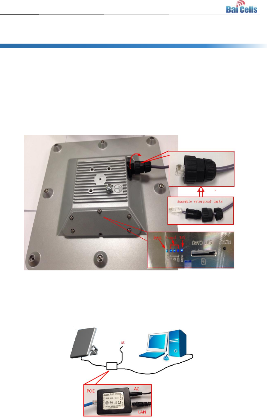
1. Assemble waterproof parts. Plug cable local connection, as shown in Figure 3-1.
2. Open the waterproof cover, and according to the instructions on the SIM card.
3. Connected to the adapter, Pay attention to the adapter interface identify.
Figure 3-1 Install the Sample
4. Mount adapter, and electricity, you can see the LED turn light, as shown in Figure
3-1.
Figure 3-2 Connection Diagram
9
4. CPE Configuration
Log in 4.1
By using a Web browser to login the CPE management page, the CPE configuration
management. Log on to the Web management page steps are as follows:
1. Power on.
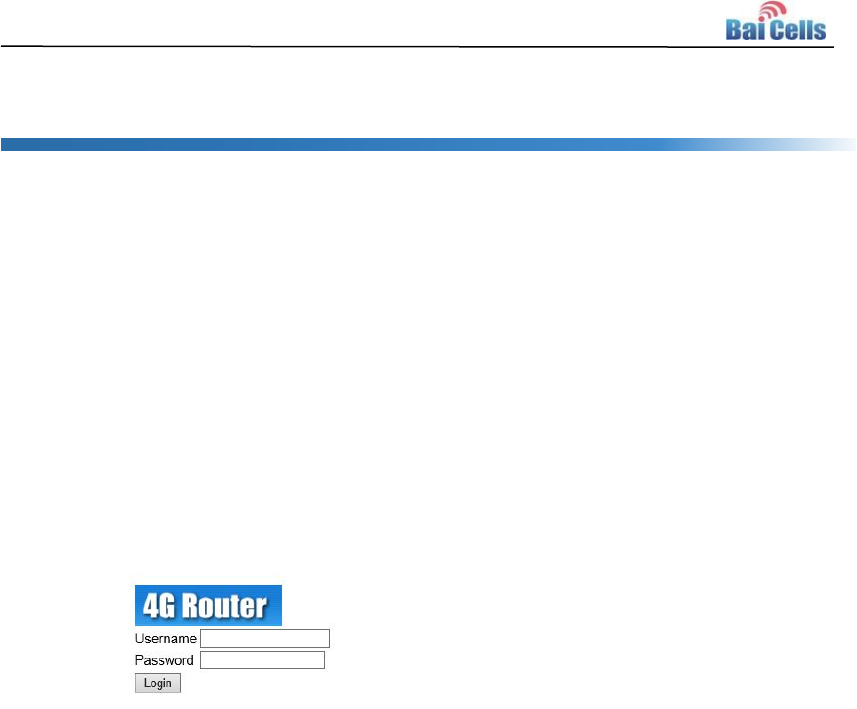
2. In the address column of browser, type in http://192.168.1.1, then press “Enter”,
login in page is shown in Figure 4-1.
Figure 4-1 Login Page
3. Enter the user name and password, click "Login" button. After password
authentication, you can log on to the web management page.
The default user name/password: admin/admin.
In order to more secure your data, it is recommended that you open the firewall,
and keep your login password, WLAN FTP passwords and password.
Basic Configuration 4.2
Network Mode
4.2.1
To set the network mode, perform the following steps:
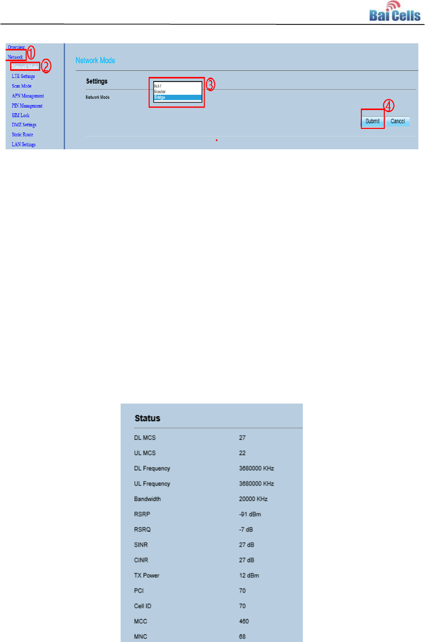
1. Choose Network Setting>Network Mode.
2. In the Network Mode area, select a mode between Route and Bridge.
3. Click “Submit”.
10
Figure 4-2 Setup Network Mod
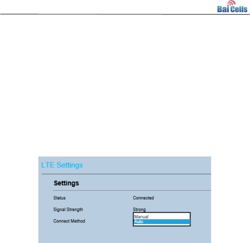
LTE Setting 4.2.2
To set the LTE Network, perform the following steps:
1. Choose Network Setting>LTE Setting.
2. In the LTE Setting area, you can configure the LTE network.
3. In the LTE Setting area, you can also view the network information such as
frequency, DL&UL MCS, RSRP, RSRQ, CINR, SINR, Tx Power, Cell ID, PCI, MCC and
MNC.
Figure 4-3 LTE Setting
11
Setting Connect Method 4.2.3
To set the LTE network connect method, perform the following steps:
1. Choose Network Setting>LTE Setting.
2. In the LTE Setting area, you can set the connect method.
3. There are two methods to connect the LTE network, it is needed to choose a
method between Auto and Manual, if you want to auto connect to the LET
network you should choose the Auto, otherwise you should choose Manual.
4. Click “Submit”.
Figure 4-4 Setup Connect Method
Manual Connect Network 4.2.4
To manual connect the network, perform the following steps:
1. Choose Network Setting>LTE Setting.
2. Set the Connect Method to Manual.
3. Click PLMN to scan the network and select a network you want to connect. If you
don’t want to use this function, it will auto select a network to connect.
4. If you want to connect to the LTE network, you should click connect button to
connect the network, otherwise you can click the button Disconnect to
disconnect from LTE network.
12
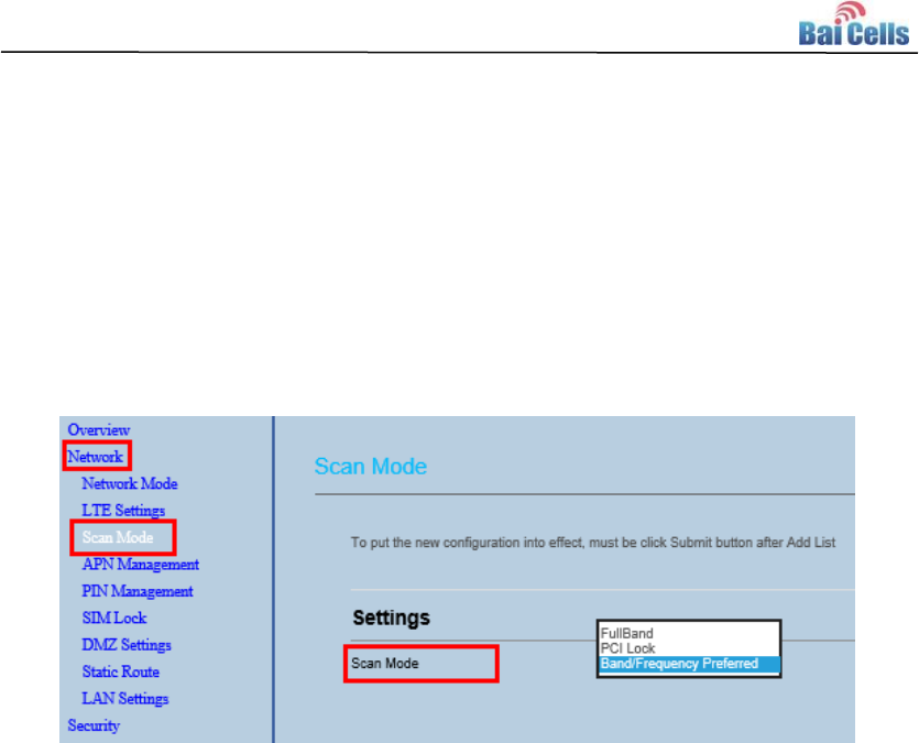
Setting Scan Mode 4.2.5
To set the LTE network scan mode, perform the following steps:
1. Choose Network Setting>LTE Setting.
2. In the LTE setting area, you can set the scan mode.
3. You can choose full Band, PCI Lock, or a band the CPE supported.
Figure 4-5 Setup Scan Mode
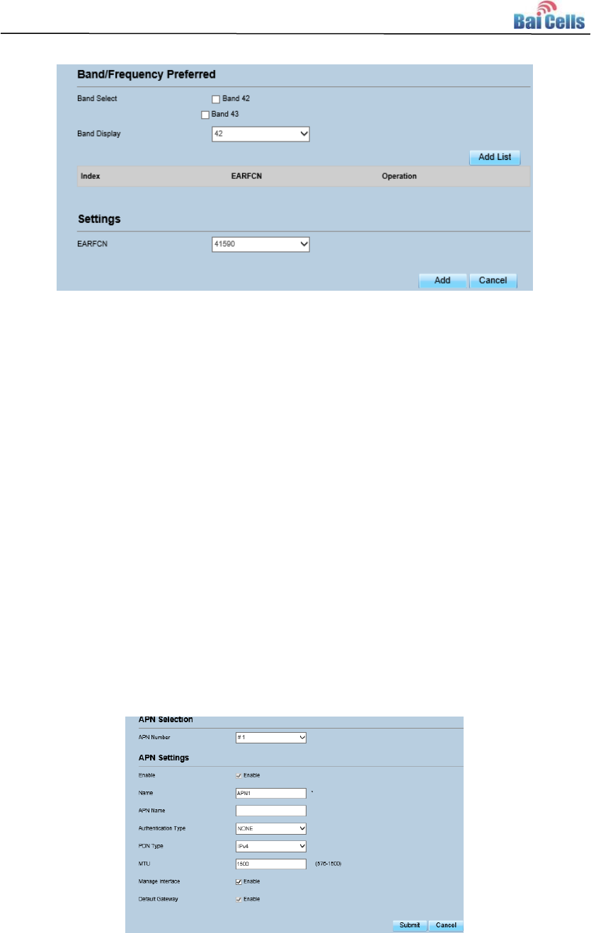
Setting Frequency (Earfcn)
4.2.6
To set the frequency, perform the following steps:
1. Choose Network Setting>LTE Setting.
2. In the LTE setting area, click to set the frequency.
3. In the Frequency Setting area, you can choose a band, then click Add list to
choose an Earfcn Number.
4. Click “Submit”.
13
Figure 4-6 Setting frequency
APN Management 4.2.7
1. To set and manage APN, perform the following steps:
2. Choose Network Setting>APN Management.
3. In the APN Management area, you can set the APN.
4. Choose an APN number which you want to set.
5. In the APN Setting area you can set the APN parameters, such as enable or
disable the APN, APN name, username, password and so on.
6. If you want set an APN as default gateway, you should check that is enabled.
7. Click “Submit”.
Figure 4-7 APN Management

14
FAQs Appendix A
A.1 The POWER indicator does not turn on.
Make sure that the power cable is connected properly and the CPE is
powered on.
Make sure that the power adapter is compatible with the CPE.
A.2 Fails to Login to the web management page.
Make sure that the CPE is started.
Verify that the CPE is correctly connected to the computer through a
network cable. If the problem persists, contact authorized local service
suppliers.
A.3 The CPE fails to search for the wireless network.
Check that the power adapter is connected properly.
Check that the CPE is placed in an open area that is far away from
obstructions, such as concrete or wooden walls.
Check that the CPE is placed far away from household electrical appliances
that generate strong electromagnetic field, such as microwave ovens,
refrigerators, and satellite dishes.
If the problem persists, contact authorized local service suppliers.
A.4 The power adapter of the CPE is overheated.
The CPE will be overheated after being used for a long time. Therefore,
power off the CPE when you are not using it.
Check that the CPE is properly ventilated and shielded from direct sunlight.
A.5 The parameters are restored to default values.
If the CPE powers off unexpectedly while being configured, the parameters
may be restored to the default settings.
After configuring the parameters, download the configuration file to quickly
restore the CPE to the desired settings
15
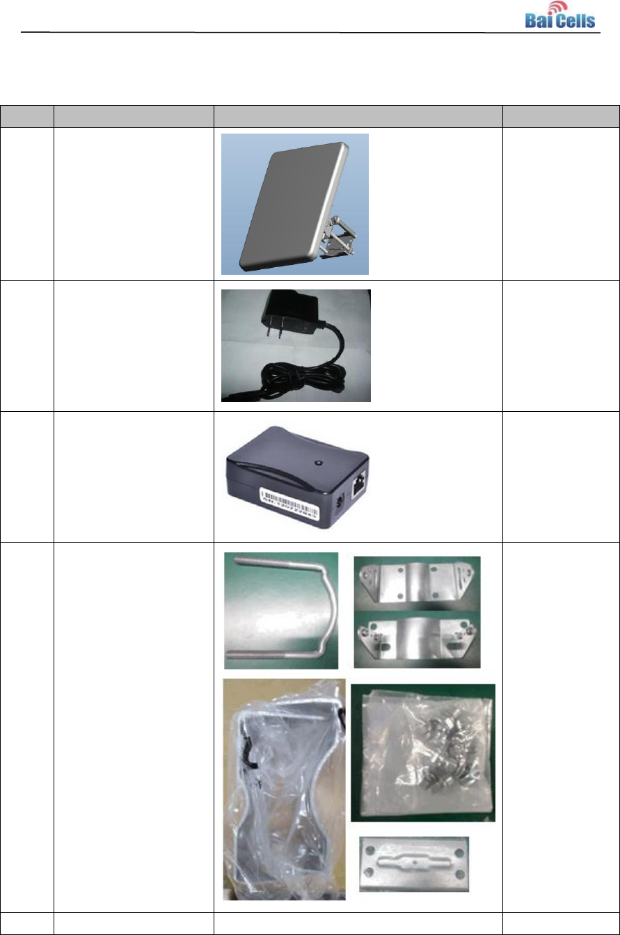
Product List Appendix B
Index
Content
Picture
Amount
1
EG7035 CPE
1
2
12V/1A adapter
1
3
PoE Combiner
1
4
Mounting bracket
1
5
User Manual
n/a
1

BaiCells EG7035 Bracket Installation Guide
V1.0
All rights reserved © BaiCells Technologies Co., Ltd.
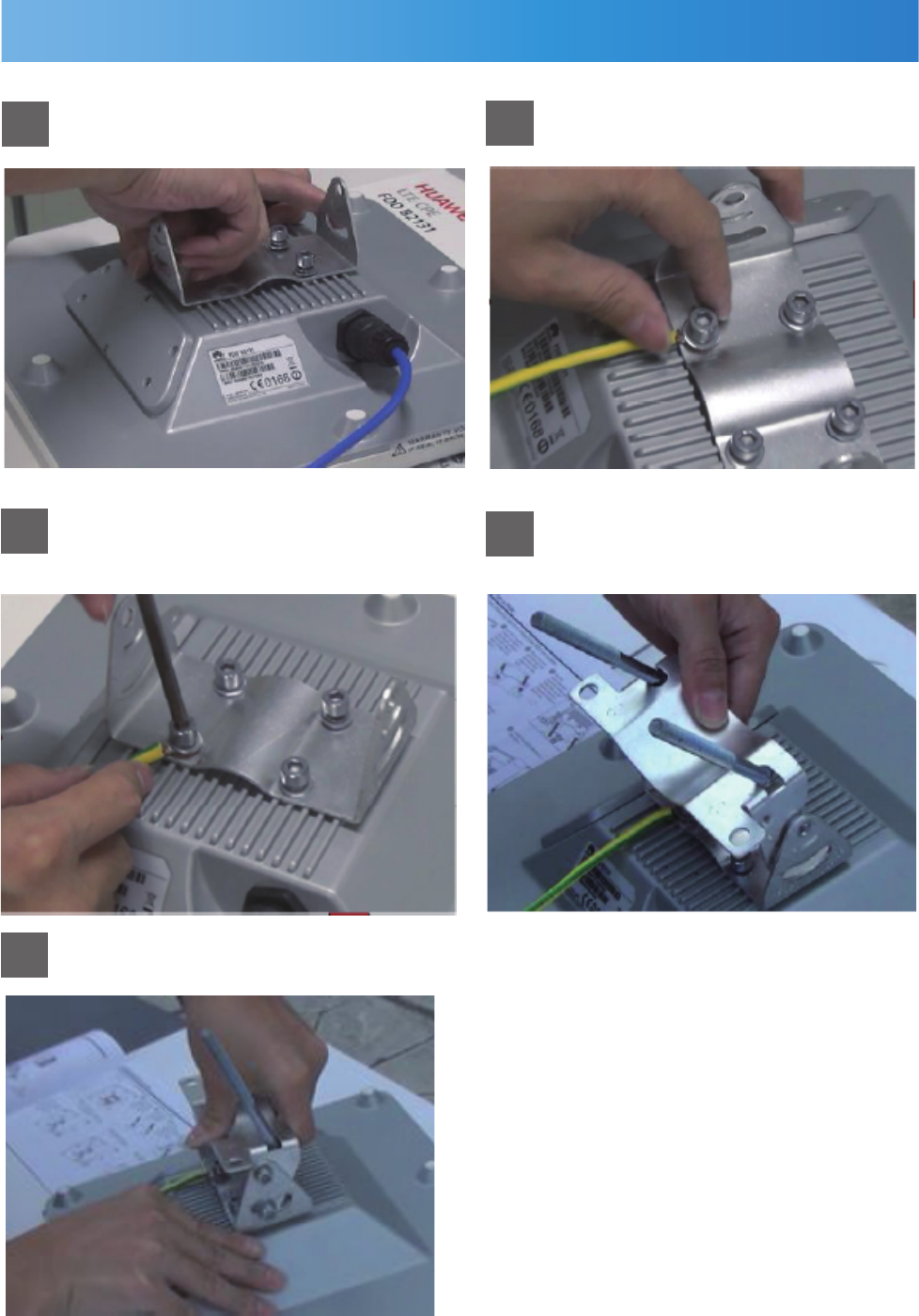
Assemble Bracket
Assemble Bracket
Install bracket and screw on, do
not tighten the screws. 2
4
Install ground wire and
lock the screw.
Tighten four screws using allen
hexagon wrench.
Screw on four bacaket srews.
Put U shape screw on bracket of
lock wall and install it on CPE
bracket.
3
5
1
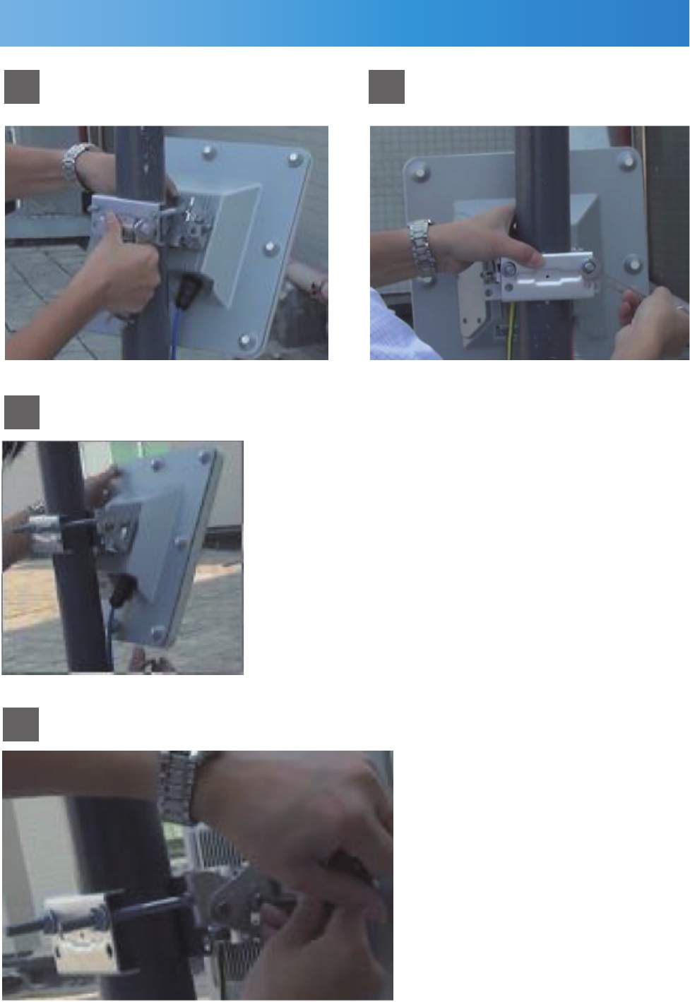
Install on Pole
Install on Pole
1 2
3
4
Loop U shape screw on pole
and put on pole bracket.
Tighten U shape screw nut
using wrench.
Tighten four screws.
Adjust CPE to a suitble position.