Balluff BISM4XX00 BIS M-400-007-001-00-S115 User Manual M 4 007 S115 854304 0910 en p65
Balluff Inc BIS M-400-007-001-00-S115 M 4 007 S115 854304 0910 en p65
Balluff >
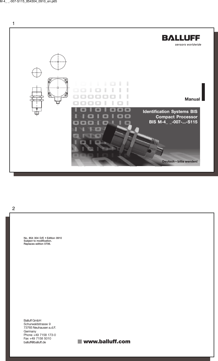
Contents
- 1. User Manual 1 of 2.pdf
- 2. User Manual 2 of 2.pdf
User Manual 1 of 2.pdf
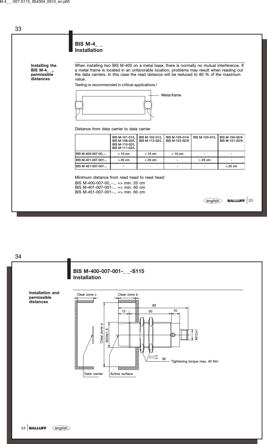
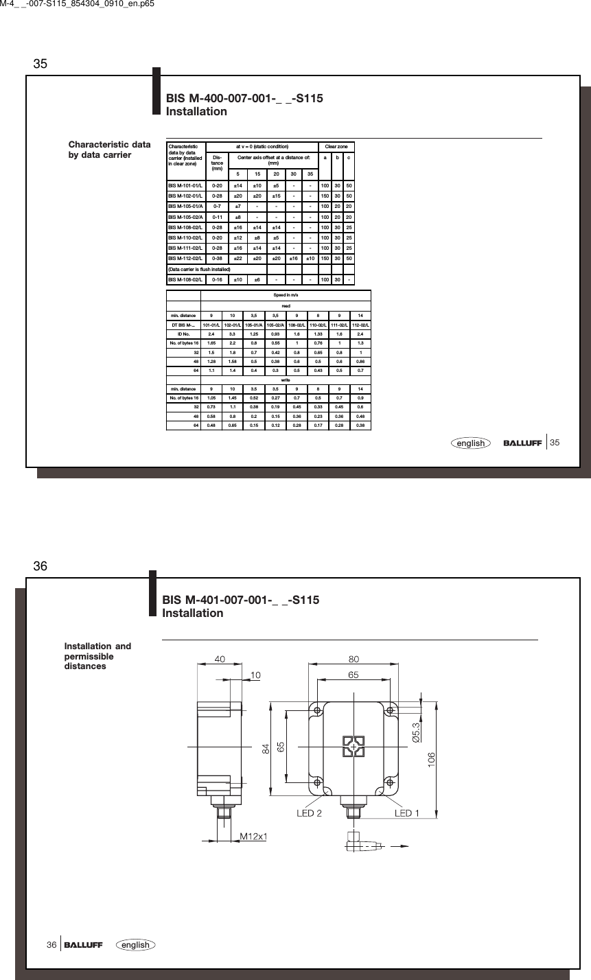
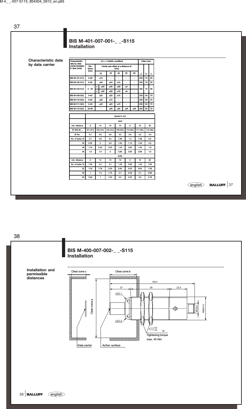
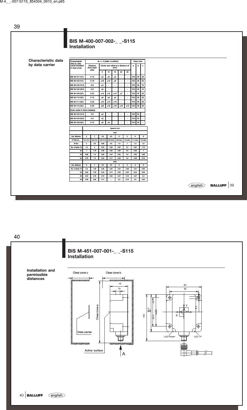
![5151englishAppendix, ASCII TableDeci-mal Hex ControlCode ASCII Deci-mal Hex ControlCode ASCII Deci-mal Hex ASCII Deci-mal Hex ASCII Deci-mal Hex ASCII Deci-mal Hex ASCII0 00 Ctrl @ NUL 22 16 Ctrl V SYN 44 2C , 65 41 A 86 56 V 107 6B k1 01 Ctrl A SOH 23 17 Ctrl W ETB 45 2D - 66 42 B 87 57 W 108 6C l2 02 Ctrl B STX 24 18 Ctrl X CAN 46 2E . 67 43 C 88 58 X 109 6D m3 03 Ctrl C ETX 25 19 Ctrl Y EM 47 2F / 68 44 D 89 59 Y 110 6E n4 04 Ctrl D EOT 26 1A Ctrl Z SUB 48 30 0 69 45 E 90 5A Z 111 6F o5 05 Ctrl E ENQ 27 1B Ctrl [ ESC 49 31 1 70 46 F 91 5B [ 112 70 p6 06 Ctrl F ACK 28 1C Ctrl \ FS 50 32 2 71 47 G 92 5C \ 113 71 q7 07 Ctrl G BEL 29 1D Ctrl ] GS 51 33 3 72 48 H 93 5D ] 114 72 r8 08 Ctrl H BS 30 1E Ctrl ^ RS 52 34 4 73 49 I 94 5E ^ 115 73 s9 09 Ctrl I HT 31 1F Ctrl _ US 53 35 5 74 4A J 95 5F _ 116 74 t10 0A Ctrl J LF 32 20 SP 54 36 6 75 4B K 96 60 ` 117 75 u11 0B Ctrl K VT 33 21 ! 55 37 7 76 4C L 97 61 a 118 76 v12 0C Ctrl L FF 34 22 " 56 38 8 77 4D M 98 62 b 119 77 w13 0D Ctrl M CR 35 23 # 57 39 9 78 4E N 99 63 c 120 78 x14 0E Ctrl N SO 36 24 $ 58 3A : 79 4F O 100 64 d 121 79 y15 0F Ctrl O SI 37 25 % 59 3B ; 80 50 P 101 65 e 122 7A z16 10 Ctrl P DLE 38 26 & 60 3C < 81 51 Q 102 66 f 123 7B {17 11 Ctrl Q DC1 39 27 ' 61 3D = 82 52 R 103 67 g 124 7C |18 12 Ctrl R DC2 40 28 ( 62 3E > 83 53 S 104 68 h 125 7D }19 13 Ctrl S DC3 41 29 ) 63 3F ? 84 54 T 105 69 i 126 7E ~20 14 Ctrl T DC4 42 2A * 64 40 @ 85 55 U 106 6A j 127 7F DEL21 15 Ctrl U NAK 43 2B +M-4_ _-007-S115_854304_0910_en.p65](https://usermanual.wiki/Balluff/BISM4XX00.User-Manual-1-of-2-pdf/User-Guide-2707949-Page-26.png)