Balluff BISM4XX00 BIS M-400-007-001-00-S115 User Manual M 4 007 S115 854304 0910 en p65
Balluff Inc BIS M-400-007-001-00-S115 M 4 007 S115 854304 0910 en p65
Balluff >
Contents
- 1. User Manual 1 of 2.pdf
- 2. User Manual 2 of 2.pdf
User Manual 1 of 2.pdf
1
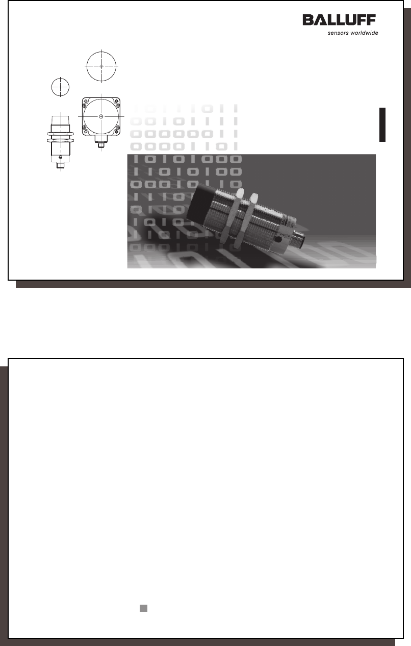
Identification Systems BIS
Compact Processor
BIS M-4_ _-007-...-S115
Manual
Deutsch – bitte wenden!
M-4_ _-007-S115_854304_0910_en.p65
2
No. 854 304 D/E • Edition 0910
Subject to modification.
Replaces edition 0706.
Balluff GmbH
Schurwaldstrasse 9
73765 Neuhausen a.d.F.
Germany
Phone +49 7158 173-0
Fax +49 7158 5010
balluff@balluff.de www.balluff.com

3
3
english
Contents
Safety Notes ............................................................................................................................... 4
Introduction BIS M-4_ _ Identification System ...................................................................... 5/6
Basic knowledge for using the BIS M-4_ _ Processor ............................................................ 7
Configuration .........................................................................................................................8-16
Programming Information .................................................................................................... 17-29
Error Numbers ..................................................................................................................... 30/31
Read/Write Times .................................................................................................................... 32
Installation RS232 ............................................................................................................... 33-42
Interface Information RS232 .................................................................................................... 43
Connection Diagrams RS232................................................................................................... 44
Installation RS422 .................................................................................................................... 45
Interface Information RS422 .................................................................................................... 46
Technical Data .......................................................................................................................... 47
Ordering Information ................................................................................................................ 48
Accessories .............................................................................................................................. 49
Symbols / Abbreviations ......................................................................................................... 50
Appendix, ASCII Table ............................................................................................................. 51
M-4_ _-007-S115_854304_0910_en.p65
4
english4
Safety Notes
BIS M-4_ _ processor together with the other BIS M system components comprise the
Identification System and may only be used for this purpose in industrial applications
corresponding to Class A of the EMC Directive.
Installation and operation are permitted by trained specialists only. Unauthorized modifica-
tions and improper use will result in loss of the right to make warranty and liability claims.
When installing the processor, follow exactly the connection diagrams provided later in this
document. Take special care when connecting the processor to external controllers, espe-
cially with respect to the selection and polarity of the connections including the power
supply.
Only approved power supplies may be used. For specific information, see the Technical
Data section.
When deploying the identification system, all relevant safety regulations must be followed.
In particular, measures must be taken to ensure that any defect in the identification system
does not result in a hazard to persons or equipment.
This includes maintaining the permissible ambient conditions and regular inspection for
proper function of the identification system and all the associated components.
At the first sign that the identification system is not working properly, it should be taken
out of service and guarded against unauthorized use.
This document applies to the processor BIS M-40_-007-00_-0_-S115 (Software version
V1.4, Hardware version V2.0 and higher).
Scope
Malfunction
Installation and
operation
Deployment and
inspection
Proper use and
operation
5
5
english
Introduction
BIS M-4_ _ Identification System
Principle
This manual is intended to guide the user in installing and commissioning the components
in the BIS M-4_ _ identification system, so that start-up time is reduced to an absolute
minimum.
The BIS M-4_ _ identification system belongs to the category of
non-contacting systems,
which can both read and write.
This dual function permits uses where not only information permanently stored in the data
carrier can be transported, but also current information can be collected and transported.
The main areas of application include
– in production for controlling material flow
(e.g., for part-specific processes),
in workpiece transport using conveying systems,
for obtaining safety-relevant data,
– in process materials organization.
The processor and the read head form a compact unit which is contained in a housing.
The data carrier represents an independent unit. It does not require line-fed power and
receives its energy from the integrated read head in the BIS M-4_ _ identification system.
The read head continuously sends a carrier signal which supplies the data carrier as soon
as the latter has reached the required distance from the read head. The read/write process
takes place during this phase. This may be static or dynamic. The data are output serially
and made available to the host system. These host systems may be:
– a control computer (e.g., industrial PC) having a serial port, or
– a programmable logic controller (PLC).
Applications
System component
function
M-4_ _-007-S115_854304_0910_en.p65
6
english6
Introduction
BIS M-4_ _ Identification System
System
components
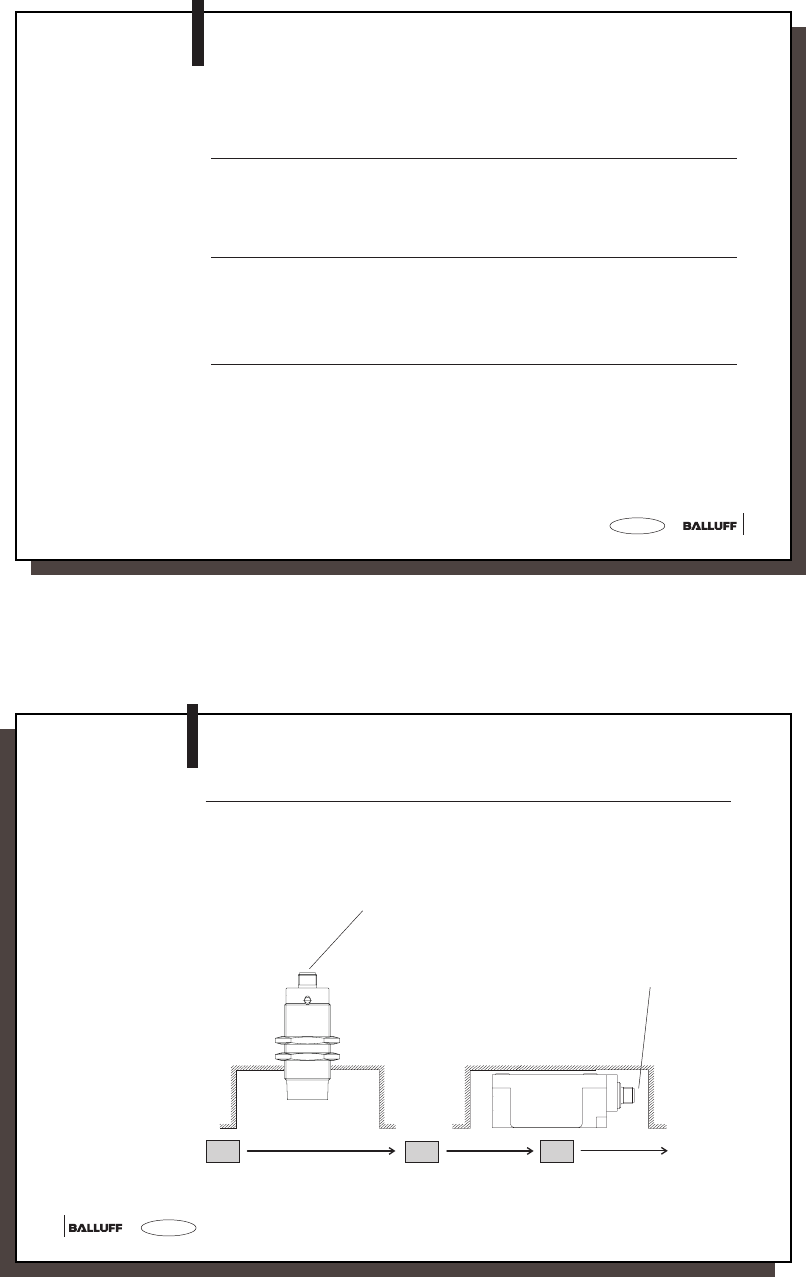
The main components of the BIS M-4_ _ identification system are
–the processor with integrated read head, and
–the data carrier(s).
Schematic
representation of an
identification system
(example)
Connections to
host system
Connections to
host system
BIS M-400...
BIS M-401...
Data carriers BIS M-1..
7
7
english
BIS M-4_ _ Processor
Basic knowledge for application
Data integrity with
CRC_16
When sending data between the read/write head and the data carrier a procedure is
required for recognizing whether the data were correctly read or written.
The processor is supplied with standard Balluff procedure of double reading and compar-
ing. In addition to this procedure a second alternative is available: CRC_16 data checking.
Here a test code is written to the data carrier, allowing data to be checked for validity at
any time or location.
Advantages of CRC_16 Advantages of double reading
Data checking even during the non-active phase No bytes on the data carrier need to be
(CT outside read/write head zone). reserved for storing a check code.
Shorter read times since each page is read only Shorter write times since no CRC needs
once. to be written.
Since both variations have their advantages depending on the application, the user is free
to select which method of data checking he wishes to use (see Configuration 8-16).
To use the CRC check method, the data carriers must be initialized. You use either data
carriers with the data map factory configured (all data are 0), or you must use the proces-
sor to write the special initialization command 'Z' to the data carriers.
It is not permitted to operate the system using both check procedures!
M-4_ _-007-S115_854304_0910_en.p65
8
english8
Configuration
Before programming, the processor configuration must be carried out, in case the factory
settings will not be used.
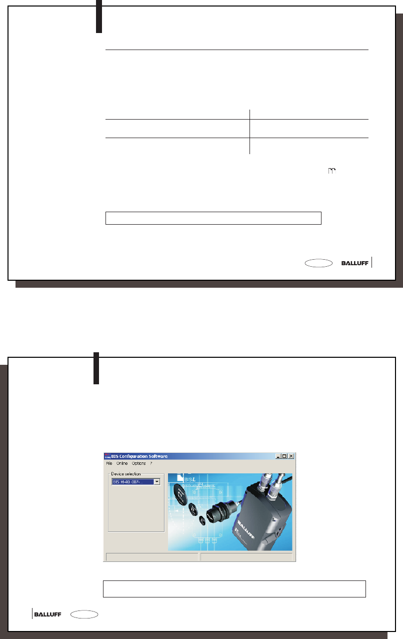
Configuration is done using a computer and the Balluff software Configuration software BIS,
and it is stored in the processor. It may be overwritten at any time. The configuration can be
stored in a file, making it accessible when required.
☞No data carrier is allowed in front of the read head while configuring the processor.
9
9
english
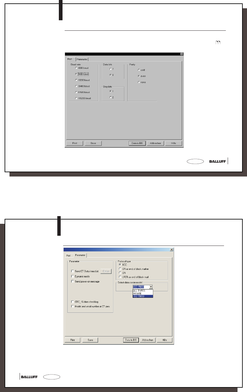
The first screen shows the parameters baud rate, number of data and stop bits, and parity
type for the serial interface selected. The graphic shows the factory settings. The other
settings are carried out in the corresponding masks which are illustrated in the following .
Configuration
Interface
BIS M-40.-007-...
M-4_ _-007-S115_854304_0910_en.p65
10
english10
Parameters
BIS M-40.-007-...
Configuration
11
11
english
Operation with blockcheck BCC is factory set. For host devices which require a terminator,
the additional use of Carriage Return 'CR' or Line Feed with Carriage Return 'LF CR' is made
available. The following page contains examples of the various possibilities.
Examples for
terminating telegrams:
Protocol Type
Configuration
Protocol Variants Telegram with command,
Address and no. of bytes
End Acknow-
ledge
Te r m i na t o r
with blockcheck BCC 'R 0000 0001' BCC <ACK> '0'
with Carriage Return 'R 0000 0001' 'CR' <ACK> '0'
with Terminator
Carriage Return
'R 0000 0001' 'CR' <ACK> '0' 'CR'
with Terminator
Carriage return and Line feed
'R 0000 0001' 'LF CR' <ACK> '0' 'LF CR'
M-4_ _-007-S115_854304_0910_en.p65
12
english12
Configuration
– Immediately send CT data
Each time another data carrier is detected, it is read according to the configuration and the
data are output. This setting eliminates the read command in dialog mode.
– Dynamic Mode
This function switches off the error-message "No data carrier present", i.e.:
-> In dynamic mode, a read or write telegram is stored until a data carrier enters the
working range of the corresponding read/write head.
-> Without dynamic mode, a read or write telegram is acknowledged with an error
message (<NAK> '1') if there is no data carrier present in front of a read/write head;
the processor goes into the ground state.
– Send power-on message
If this function is activated, the processor sends the device name and software version
as soon as power is turned on.
– Serial number when CT Pres.
If the function "Type and serial number when CT pres." is parameterized, the number of
the data carrier type followed by the 8-byte unique serial number (at Mifare 4 bytes
+ 4 bytes '0Hex') is sent.
Parameters
13
13
english
Parameters
(continued)
Configuration
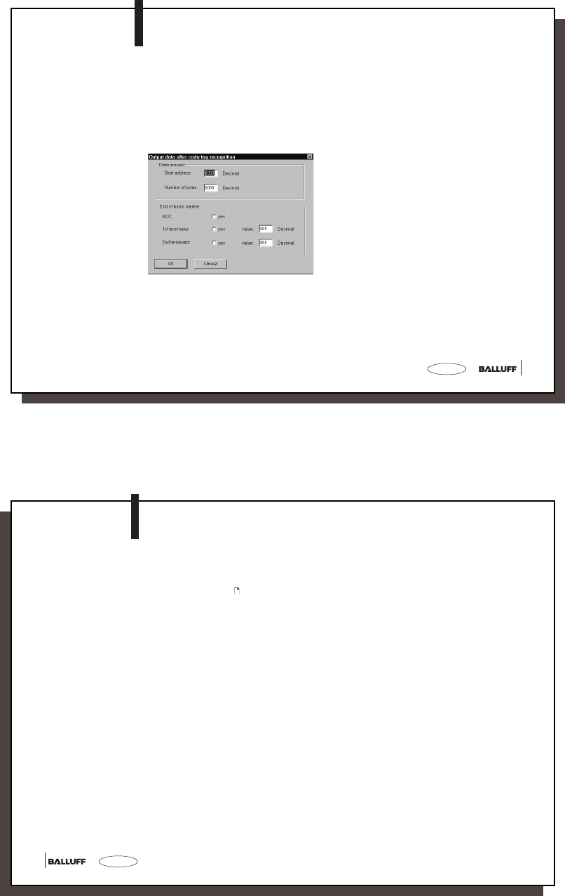
Read and send data carrier data without direct command:
The specified data amount (number of bytes beginning at start address) is read from the newly
detected data carrier.
After reading, the data are automatically output.
If desired, a BCC and/or 1 or 2 freely definable terminators may be sent also.
M-4_ _-007-S115_854304_0910_en.p65
14
english14
Parameters
(continued)
Configuration
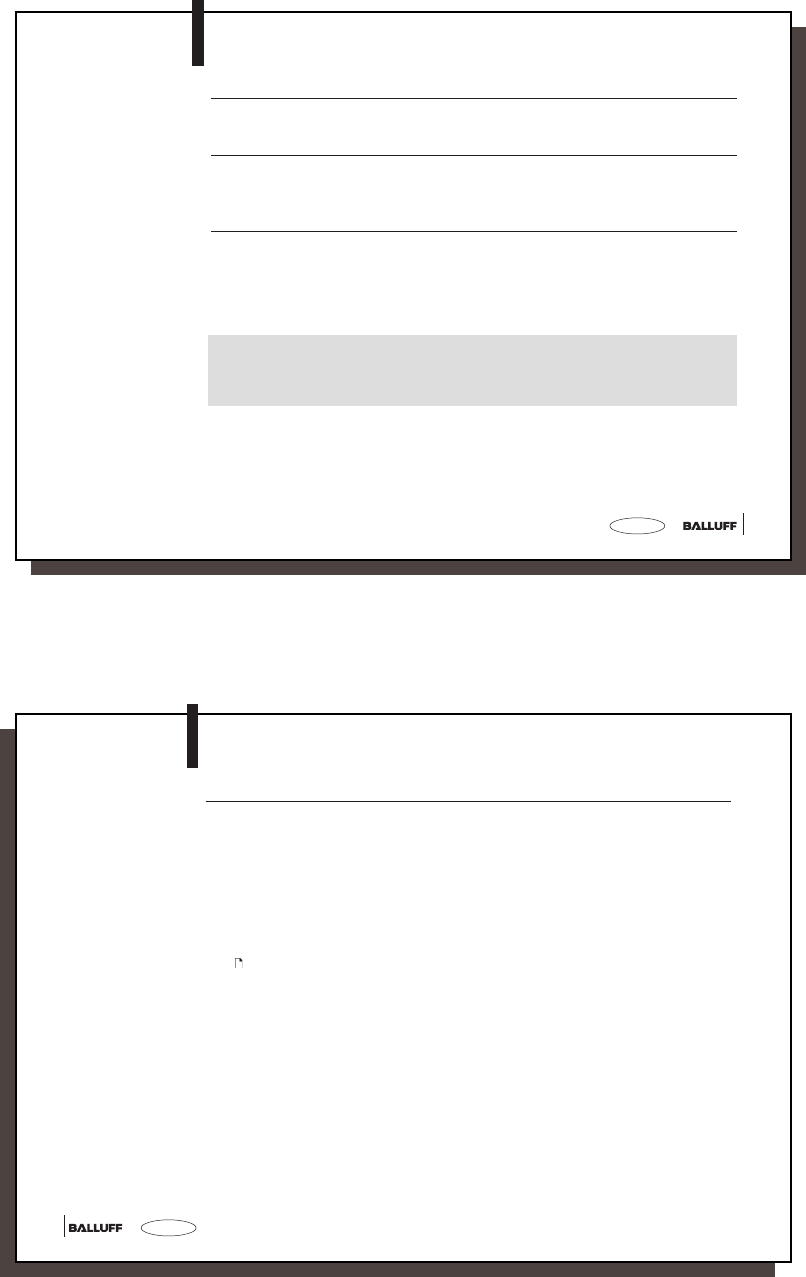
– CRC_16 initialization
To be able to use the CRC_16 check, the data carrier must first be initialized with the com-
mand identifier Z (see 28). The CRC_16 initialization is used like a normal write job. The
latter is rejected (with an error message) if the processor recognizes that the data carrier does
not contain the correct CRC_16 checksum. Data carriers as shipped from the factory (all data
are 0) can immediately be written with CRC-checked data.
If CRC_16 data checking is activated, a special error message is output to the interface
whenever a CRC_16 error is detected.
If the error message is not caused by a failed write request, it may be assumed that one or
more memory cells on the data carrier is defective. That data carrier must then be replaced.
If the CRC error is however due to a failed write request, you must reinitialize the data carrier
in order to continue using it.
15
15
english
Configuration
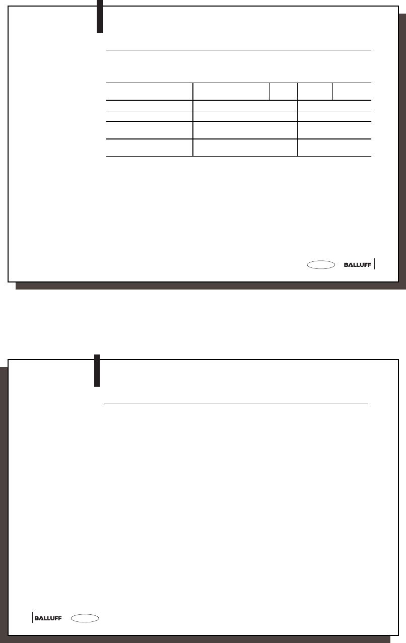
If CRC_16 was parameterized and a data carrier is recognized whose CRC_16 checksum is
incorrect, the read data are not output. The CT present LED comes on and the digital output is
set - the data carrier can be processed using the initialization command (Z).
The checksum is written to the data carrier as a 2-byte datum for each CRC block (corre-
sponds to 16 bytes). 2 bytes are used (lost) for each CRC block, i.e., the CRC block contains
only 14 bytes of user data. This means that the actual usable number of bytes is reduced:
CRC_16 and
Codetag Present
CRC_16
Mifare
Balluff data carrier type Manufacture Name Memory capacity Usable bytes using CRC Memory type
BIS M-1_ _-01 Philips Mifare Classic 752 Byte 658 Byte EEPROM
ISO15693
Balluff data carrier type Manufacture Name Memory capacity Usable bytes using CRC Memory type
BIS M-1_ _-02 Fujitsu MB89R118 2000 Byte 1750 Byte FRAM
BIS M-1_ _-031Philips SL2ICS20 112 Byte 98 Byte EEPROM
BIS M-1_ _-041Texas Inst. TAG-IT Plus 256 Byte 224 Byte EEPROM
BIS M-1_ _-051Infineon SRF55V02P 224 Byte 196 Byte EEPROM
BIS M-1_ _-061EM EM4135 288 Byte 252 Byte EEPROM
BIS M-1_ _-071Infineon SRF55V10P 992 Byte 868 Byte EEPROM
Supported data
carriers and
memory capacity
1 on request
M-4_ _-007-S115_854304_0910_en.p65
16
english16
Configuration
Select the data carrier type, you want to process:
- ALL TYPES
- MIFARE
- ISO 15693
ALL TYPES: All data carriers supported by Balluff can be processed.
MIFARE: All Mifare data carriers supported by Balluff can be processed.
ISO 15693: All ISO15693 data carriers supported by Balluff can be processed.
(See 15 "Supported data carriers and memory capacity".)
Data carrier type

17
17
english
The preceding sections describe basic telegram sequence, and configuration and wiring of
the interfaces. What now follows is information about the proper construction of the telegrams
themselves.
Specific telegrams exist in the BIS M Identification System for particular tasks. They
always begin with the command which is associated with the telegram type.
'L' Read the data carrier with 2-byte reservation
'P' Write to the data carrier with 2-byte reservation
'C' Write a constant value to the data carrier with read/write select with
2-byte reservation
'R' Read the data carrier
'W' Write to the data carrier
'Q' Restart the processor (acknowledge)
'Z' Initialize CRC_16 data check
'U' Read data carrier ID and output with status byte.
Please note:
– Continuous querying on the interface is not permitted!
Telegram types with
their associated
commands
(ASCII characters)
Programming Information
M-4_ _-007-S115_854304_0910_en.p65
18
english18
Telegram Contents Start address and The start address (A3, A2, A1, A0) and the number of bytes to send
no. of bytes (L3, L2, L1, L0) are sent in decimal as ASCII characters. For the start
address, the range 0000 to "memory capacity -1" can be used, and for
the number of bytes 0001 to "memory capacity".
A3 ... L0 represent one ASCII character each.
Please note: Start address + number of bytes may not exceed
1024 bytes.
Reserved The commands 'L' (read data carrier with L-command), 'P' (write to
data carrier with P-command), 'C' (write to the data carrier with
C-command) and 'Z' (initialize CRC_16 data check) cause the 2 bytes
given after the address and the number of 8 bytes to be read/written to
be reserved with '1'.
Acknowledge The acknowledgement <ACK> '0' is sent by the Identification System if
the serially transmitted characters were recognized as correct and there
is a data carrier in the active zone of a read/write head. In the 'R'
command, the <ACK> '0' is only sent if the data is ready for transmission.
<NAK> + Error No.' is sent if an error was recognized or if there is no
data carrier in the active zone of a read/write head.
Start <STX> starts the data transmission.
Transmitted The data are transmitted code transparent (no data conversion).
Bytes
Programming Information
19
19
english
The BCC block check is formed as an EXOR of the serially transmitted binary characters of
the telegram block. Example: Read 128 bytes starting at address 13.
The command line without BCC is: 'L 0013 0128 11'. The BCC is formed:
'L = 0100 1100 EXOR
0 = 0011 0000 EXOR
0 = 0011 0000 EXOR
1 = 0011 0001 EXOR
3 = 0011 0011 EXOR
0 = 0011 0000 EXOR
1 = 0011 0001 EXOR
2 = 0011 0010 EXOR
8 = 0011 1000 EXOR
1 = 0011 0010 EXOR
1' = 0011 0000 EXOR
Block check result: BCC = 0100 0101 = 'E'
If necessary the finish using block check BCC can be replaced with a special ASCII character.
This is:
– Carriage Return 'CR'
For hosts which always require a terminator character, this must always be included in the
telegrams. Available are:
– Carriage Return 'CR' or
– Line Feed with Carriage Return 'LF CR'.
The various protocol variants are represented on the following .
See also: Configuration starting on 8.
BCC Block Check
Variants for finish
with BCC,
Terminator
Programming Information
M-4_ _-007-S115_854304_0910_en.p65
20
english20
Description of
Various Protocol
Variants
Programming Information
The respective positions for the additional terminator are shown in the tables in italics.
Reference is now made to the command string 'L 0013 0128 11 E' with 'E' as BCC (see
preceding ). This command string is here shown in its possible variants; also shown are
the various forms of acknowledgement with and without terminator:
Command line from Acknowledge from BIS Acknowledge from BIS
host system to BIS for correct reception for incorrect reception
with BCC
but no terminator No terminator No terminator
'L 0013 0128 11 E' <ACK> '0' <NAK> '1'
with 'CR' instead of BCC,
no terminator No terminator No terminator
'L 0013 0128 11 CR' <ACK> '0' <NAK> '1'
no BCC,
with terminator 'CR' with terminator 'CR' with terminator 'CR'
'L 0013 0128 11 CR' <ACK> '0 CR' <NAK> '1 CR'
no BCC,
with terminator 'LF CR' with terminator 'LF CR' with terminator 'LF CR'
'L 0013 0128 11 LF CR' <ACK> '0 LF CR' <NAK> '1 LF CR'
For <NAK> with error number a '1' was used here (no data carrier present) as an error ex-
ample.
21
21
english
Values inside apostrophes represent the respective character(s) in ASCII code.
1) The command 'Quit' is not permitted at this point.
2) Instead of block check BCC, depending on protocol variant either Carriage Return 'CR' or LIne Feed with Carriage Return may be used.
3) <ACK> '0' is returned as acknowledgement if there is no error, or <NAK> + Error No. if an error occurs.
4) For protocol variants which always require a terminator, either 'CR' or 'LF CR' must be inserted here.
5) The number of bytes to send may not exceed 1024 bytes.
Programming Information
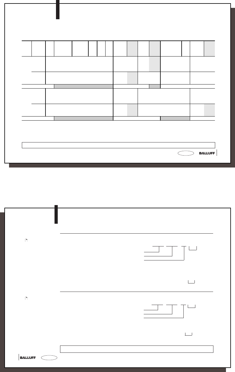
Read from data carrier with command L
Write to data carrier with command P
Task Data Flow Com-
mand
Start address
of first byte to
be sent
Number of
bytes to be
sent
re-
serv-
ed
End
2)
Acknow-
ledge
3)
Termi-
nator
4)
Start
trans-
mission
Termi-
nator
4)
Data (from start
address to start
address
+ no. of bytes)
End
2)
Acknow-
ledge
3)
Termi-
nator
4)
Read from host
system to
BIS
'L' A3 A2 A1 A0
'0 0 0 0'
to
memory
capacity -1
L3 L2 L1 L0
'0 0 0 1'
to
memory
capacity 5)
'1' '1'
BCC
or
see
2)
<STX> 'CR' or
'LF CR'
from BIS
to host
system
<ACK>'0'
or <NAK>
+ Error-
No.
'CR' or
'LF CR'
D1 D2 D3 ... Dn BCC
or
see
2)
1) 1)
Write from host
system to
BIS
'P' A3 A2 A1 A0
'0 0 0 0'
to
memory
capacity -1
L3 L3 L1 L0
'0 0 0 1'
to
'memory
capacity 5)
'1' '1'
BCC
or
see
2)
<STX> D1 D2 D3 ... Dn BCC
or
see
2)
from BIS
to host
system
<ACK>'0'
or <NAK>
+ Error-
No.
'CR' or
'LF CR'
<ACK>'0'
or <NAK>
+ Error-
No.
'CR' or
'LF CR'
1) 1)
M-4_ _-007-S115_854304_0910_en.p65
22
english22
-> Read 10 bytes starting at address 50 of the data carrier.
The host sends 'L 0 0 5 0 0 0 1 0 1 1 H' BCC (48Hex)
Address of first byte to read
Number of bytes to read
reserved
The BIS processor acknowledges with <ACK> '0'
The host system gives the start command <STX>
The BIS processor provides the data from the data carrier 1 2 3 4 5 6 7 8 9 0 '1' BCC (31Hex)
-> Write 5 bytes starting at address 100 of the data carrier.
The host sends 'P 0 1 0 0 0 0 0 5 1 1 L' BCC (54Hex)
Address of first byte to write
Number of bytes to write
reserved
The BIS processor acknowledges with <ACK> '0'
The host system gives the start command and data <STX> 1 2 3 4 5 '3' BCC (33Hex)
The processor acknowledges with <ACK> '0'
Values inside apostrophes represent the respective character(s) in ASCII code.
Telegram example
for 21:
Write to data carrier
with command P
with block check (BCC)
Programming Information
Telegram example
for 21:
Read from data
carrier with
command L
with block check (BCC)
23
23
english
Programming Information
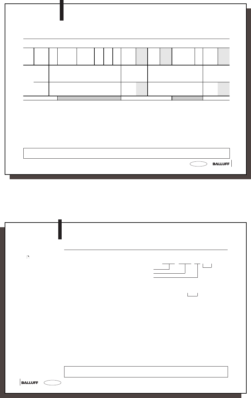
Writing a constant value in the data carrier with command C
This command can be used to erase a data carrier data. One saves the time for the transmission of the write byte.
Data within angle brackets are control characters.
Values inside apostrophes represent the respective character(s) in ASCII code.
1) The command 'Quit' is not permitted at this point.
2) Instead of block check BCC, depending on protocol variant either Carriage Return 'CR' or LIne Feed with Carriage Return may be used.
3) <ACK> '0' is returned as acknowledgement if there is no error, or <NAK> + 'Error No.' if an error occurs.
4) For protocol variants which always require a terminator, either 'CR' or 'LF CR' must be inserted here.
5) The number of bytes to send may not exceed 1024 bytes.
Ta s k D a t a F l o w C o m-
mand
Start address
of first byte to
be sent
Number of
bytes to be
sent
re-
serv-
ed
End
2)
Acknow-
ledge
3)
Termi-
nator
4)
Start
trans-
mission
Termi-
nator
4)
Data (from start
address to start
address
+ no. of bytes)
End
2)
Acknow-
ledge
3)
Termi-
nator
4)
Write from host
system to
BIS
'C' A3 A2 A1 A0
'0 0 0 0'
to
memory
capacity -1
L3 L3 L1 L0
'0 0 0 1'
to
memory
capacitity 5)
'1' '1'
BCC
or
see
2)
<STX> D BCC
or
see
2)
from BIS
to host
system
<ACK>'0'
or <NAK>
+ Error-
No.
'CR' or
'LF CR'
<ACK>'0'
or <NAK>
+ Error-
No.
'CR' or
'LF CR'
1) 1)
M-4_ _-007-S115_854304_0910_en.p65
24
english24
Programming Information
-> Write 101 bytes of ASCII data value 0 (30Hex) starting at address 20 of the data carrier.
The host sends 'C 0 0 2 0 0 1 0 1 1 1 A' BCC (41Hex)
Address of first byte to write
Number of bytes to write
reserved
The BIS processor acknowledges with <ACK> '0'
The host system gives the start command and data <STX> '0 2' BCC (32Hex)
The processor acknowledges with <ACK> '0'
Data within angle brackets are control characters.
Values inside apostrophes represent the respective character(s) in ASCII code.
Telegram example
for 23:
Write to data carrier
with command C
with block check (BCC)
25
25
english
Programming Information
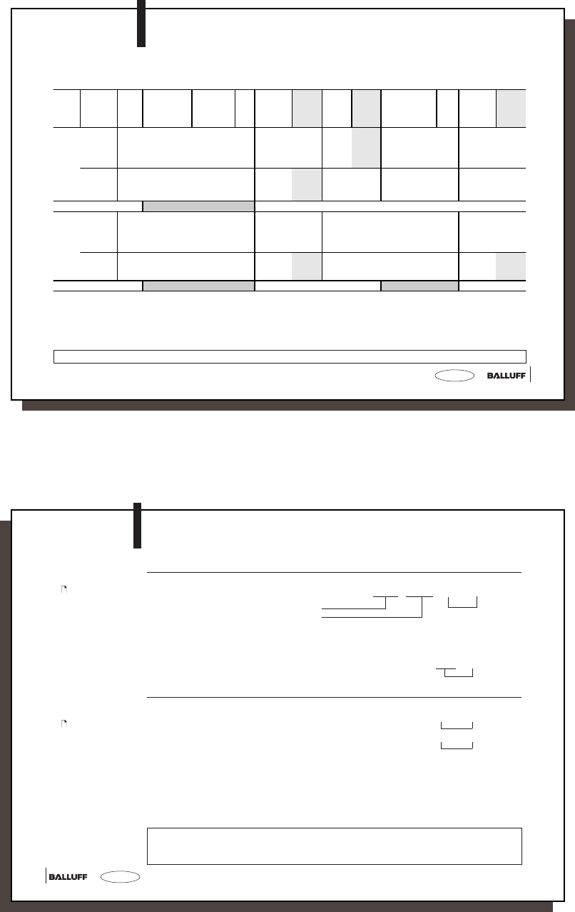
Read from Data carrier, Write to Data carrier
Values inside apostrophes represent the respective character(s) in ASCII code.
1) The command 'Quit' is not permitted at this point.
2) Instead of block check BCC, depending on protocol variant either Carriage Return 'CR' or LIne Feed with Carriage Return may be used.
3) <ACK> '0' is returned as acknowledgement if there is no error, or <NAK> + Error No. if an error occurs.
4) For protocol variants which always require a terminator, either 'CR' or 'LF CR' must be inserted here.
5) The number of bytes to send may not exceed 1024 bytes.
Task Data Flow Com-
mand
Start address
of first byte to
send
Number of
bytes to
send
End
2)
Acknow-
ledge
3)
Te rm i -
nator
4)
Start
trans-
mission
Te rm i -
nator
4)
Data (from start
address to start
address
+ no. of bytes)
End
2)
Acknow-
ledge
3)
Te rm i -
nator
4)
Read from host
system to
BIS
'R' A3 A2 A1 A0
'0 0 0 0'
to
memory
capacity -1
L3 L3 L1 L0
'0 0 0 1'
to
memory
capacity 5)
BCC
or
see
2)
<STX> 'CR' or
'LF CR'
from BIS
to host
system
<ACK>'0'
or <NAK>
+ Error-No.
'CR' or
'LF CR'
D1 D2 D3 ... Dn BCC
or
see
2)
1)
Write from host
system to
BIS
'W' A3 A2 A1 A0
'0 0 0 0'
to
memory
capacity -1
L3 L3 L1 L0
'0 0 0 1'
to
memory
capacity 5)
BCC
or
see
2)
<STX> D1 D2 D3 ... Dn BCC
or
see
2)
from BIS
to host
system
<ACK>'0'
or <NAK>
+ Error-No.
'CR' or
'LF CR'
<ACK>'0'
or <NAK>
+ Error-No.
'CR' or
'LF CR'
1) 1)
M-4_ _-007-S115_854304_0910_en.p65
26
english26
Programming Information
Read from Data carrier: -> Read 10 bytes starting at address 50.
The host sends 'R 0 0 5 0 0 0 1 0 V' BCC (56Hex)
Address of first byte to read
Number of bytes to read
The BIS processor acknowledges with <ACK> '0'
The host gives the start command <STX>
The BIS processor provides the data
from the data carrier 1 2 3 4 5 6 7 8 9 0 'SOH' BCC (01Hex)
Write to Data carrier: -> Write 5 bytes starting at address 100.
The host system sends 'W 0 1 0 0 0 0 0 5 S' BCC (53Hex)
The BIS processor acknowledges with <ACK> '0'
The host sends the data <STX> 1 2 3 4 5 '3' BCC (33Hex)
The BIS processor acknowledges with <ACK> '0'
Telegram example
for 25:
Read from Data
carrier
with block check (BCC)
The 'R' and 'W' commands represent a subtype of the 'L' and 'P' commands.
Values inside apostrophes represent the respective character(s) in ASCII code.
Telegram example
for 25:
Write to Data carrier
with block check (BCC)
27
27
english
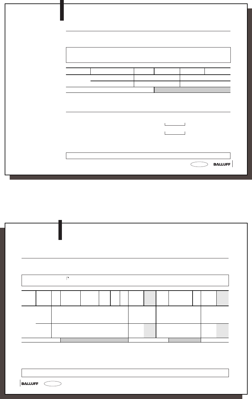
Restart the
Processor (Quit)
Programming Information
Values inside apostrophes represent the respective character(s) in ASCII code.
Sending the Restart command causes a telegram in process to be aborted and puts the
processor in the ground state. After this telegram is acknowledged, an approx. 500 ms pause
should be allowed before starting a new telegram.
Important! The Quit command is not permitted while the processor is waiting for a terminator
(BCC, 'CR' or 'LF CR'). In this situation, the Quit would be incorrectly interpreted as a termina-
tor or datum.
1) The command 'Quit' is not permitted at this point.
2) Instead of block check BCC, depending on protocol variant either Carriage Return 'CR' or LIne Feed with
Carriage Return may be used.
Put the BIS system into the ground state.
The host sends 'Q Q' BCC (51Hex)
The BIS processor acknowledges with 'Q Q' BCC (51Hex)
Telegram example:
Restart the Processor
(Quit)
with block check (BCC)
Task Data Flow Command End 2) Acknowledge End 2)
Restart
(Quit)
from host system to BIS 'Q' BCC or see 2)
from BIS to host system 'Q' BCC or see 2)
1)
M-4_ _-007-S115_854304_0910_en.p65
28
english28
Initialize CRC_16 data check
This telegram initializes a data carrier located at the read/write head for use of CRC_16 data checking. This tele-
gram must also be send again if a CRC error results from a failed write operation, i.e., the data carrier must be
reinitialized in order to use it again.
Please note the table on 15! The indicated number of usable bytes may not be exceeded, i.e., the sum of start address
plus number of bytes must not exceed the data carrier memory capacity!
1) The command 'Quit' is not permitted at this point.
2) Instead of BCC block check, depending on the protocol variant either Carriage Return 'CR' or Line Feed with Carriage Return 'LF CR'
may be used.
3) <ACK> '0" is sent as an acknowledgement if there was no error, or <NAK> + 'Error-No.' if there was an error.
4) For protocol variants which always need a terminator, either 'CR' or 'LF CR' must be inserted here.
The characters between the apostrophes represent the respective ASCII character(s). '_' = Space = ASCII 20Hex.
Programming Information
Task Data Flow Com-
mand
Start address
of first byte to
be sent
Number of
bytes to be
sent
reserv-
ed
End
2)
Acknow-
ledge
3)
Te r mi -
nator
4)
Start
trans-
mission
Data (from start
address to start
address
+ no. of bytes)
End
2)
Acknow-
ledge
3)
Te r mi -
nator
4)
Initialize
CRC_16
range
from host
system to
BIS
'Z'A3 A2 A1 A0
'0 0 0 0'
to usable
bytes at
CRC -1
L3 L3 L1 L0
'0 0 0 1'
to usable
bytes at
CRC -1
'1' '1'
BCC
or
see
2)
<STX> D1 D2 D3 .... Dn BCC
or
see
2)
from BIS
to host
system
<ACK>'0'
or <NAK>
+ Error-
No.
'CR' or
'LF CR'
<ACK>'0'
or <NAK>
+ Error-
No.
'CR' or
'LF CR'
1) 1)

29
29
english
With the telegram the status byte (Tag Present), data carrier type and data carrier ID of
data carriers are read and sent. In contrast to the standard command, here the reply is not
an <ACK> or <NAK>, but rather a fixed data telegram.
Task Data Flow Command End 2) Status message End 2)
Check Status
Message
From host system to BIS 'U' BCC
or see 2)
From BIS to host system S1 Type1 ID1 BCC
or see 2)
1)
1) The Command 'Quit' is not permitted at this point.
2) Instead of BCC block check, depending on the protocol variant either Carriage Return 'CR' or Line Feed
with Carriage Return 'LF CR' may be used.
S1 = Status byte ('1' no data carrier; '0' data carrier)
Typ1 = Number of the data carrier type (see 15 "Supported data carriers and memory
capacity")
ID1 = ID of the data carrier type is 8 bytes long (at Mifare 4 Byte + 4 Byte '0Hex')
The host sends 'U U' BCC (55Hex)
The BIS processor acknowledges with '0J123400005' BCC (35Hex) if a data carrier was
recognized
The BIS processor acknowledges with '1xxxxxxxxx1' BCC (31Hex) if no data carrier
was recognized
(x = 'NUL')
Values inside apostrophes represent the respective character(s) in ASCII code.
Query
status byte,
data carrier type,
data carrier ID
Programming Information
Telegram example:
Query status byte,
data carrier type and
data carrier ID
M-4_ _-007-S115_854304_0910_en.p65
30
english30
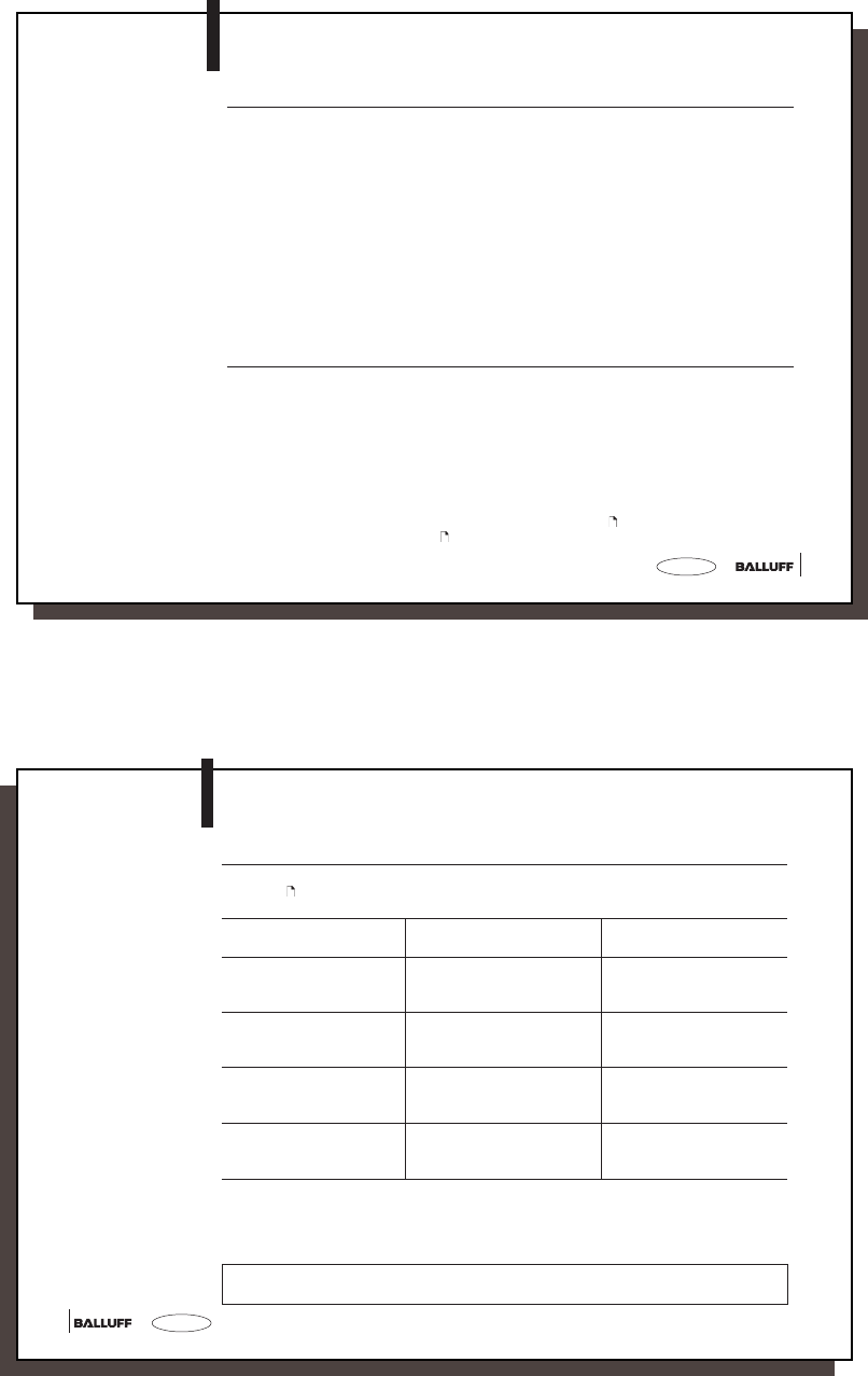
Error Numbers The BIS M-4_ _ always outputs an error number. The meaning of these error numbers is
indicated in the following table.
Error Numbers
No. Error Description Effect
1 No data carrier present Telegram aborted,
processor goes into ground state.
2 Read error Read telegram aborted,
processor goes into ground state.
Possible read error:
- data carrier removed
- Key false
4 Write error Write telegram aborted,
processor goes into ground
state.
Possible write error:
- data carrier removed
- Key false
CAUTION: An aborted write
could cause new data to be
written to the data carrier
which may be incomplete! *)
6 Interface error Processor goes into ground state.
(parity or stop bit error)
7 Telegram format error Processor goes into ground state. Possible format errors:
- Command is not 'L', 'P', 'C', 'R', 'W', 'Z' or 'U'.
- Start address or number of bytes exceed permissible range
*) Note: If a CRC data check is used, error message “E” could result if error 4 was not cleared.
31
31
english
Error Numbers
(continued)
Error Numbers
No. Error Description Effect
8 BCC error, the trans-
mitted BCC is wrong
Telegr am is ab or te d ,
processor goes into ground state.
D CT error Bad CT signal,
processor goes into ground state.
E CRC error: the CRC on the
data carrier is wrong. *)
Telegram aborted,
processor goes into ground state.
*) Note: If a CRC data check is used, error message “E” could result if in the preceding command
error 4 was reported.
M-4_ _-007-S115_854304_0910_en.p65
32
english32
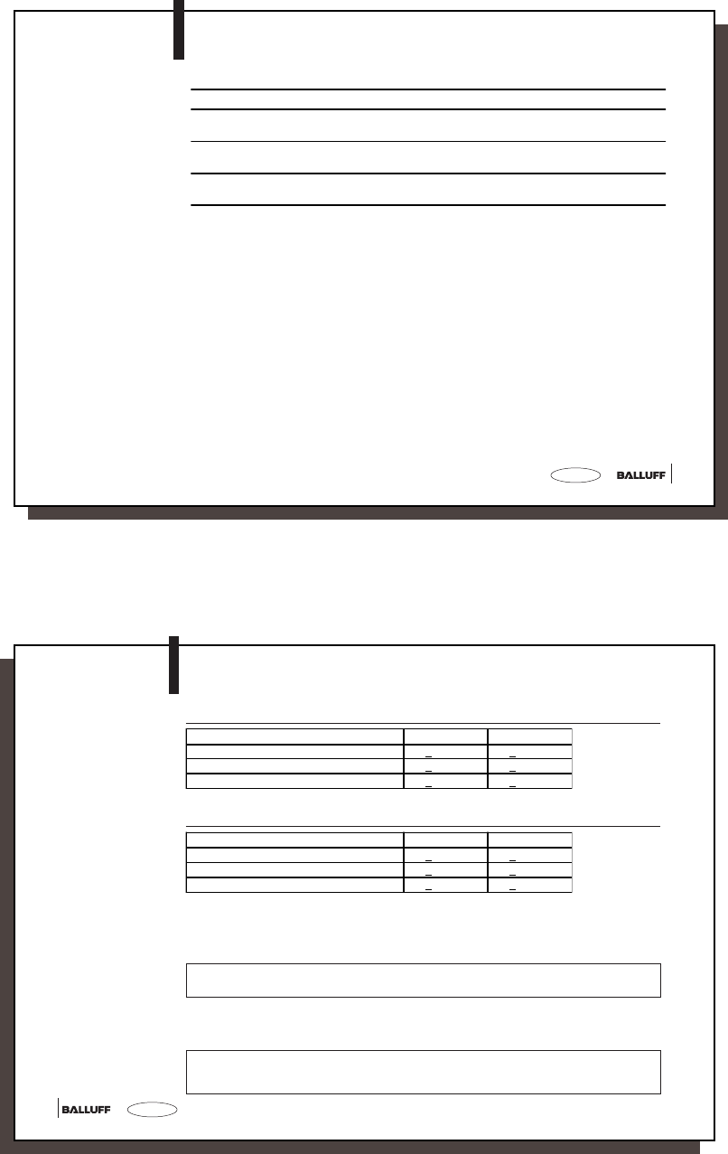
Read/Write Times
All data are typical values. Deviations are possible depending on the application and combination
of read/write head and data carrier!
The data apply to static operation, no CRC_16 data checking.
☞
Variations in the ms range are possible.
Electrical interference may increase the read/write times.
☞
Read times
Write times
Data carrier with each 16 bytes/block BIS M-1_ _-01 BIS M-1_ _-02
Time for data carrier recognition/serial ID < 20 ms < 30 ms
Read bytes 0 to 15 < 20 ms < 30 ms
For each additional 16 bytes add another < 10 ms < 15 ms
Data carrier with each 16 bytes/block BIS M-1_ _-01 BIS M-1_ _-02
Time for data carrier recognition/serial ID < 20 ms < 30 ms
Write bytes 0 to 15 < 40 ms < 65 ms
For each additional 16 bytes add another < 30 ms < 45 ms
33
33
english
BIS M-4_ _
Installation
Installing the
BIS M-4_ _,
permissible
distances
When installing two BIS M-400 on a metal base, there is normally no mutual interference. If
a metal frame is located in an unfavorable location, problems may result when reading out
the data carriers. In this case the read distance will be reduced to 80 % of the maximum
value.
Testing is recommended in critical applications !
Distance from data carrier to data carrier
Metal frame
Minimum distance from read head to read head:
BIS M-400-007-00_-... => min. 20 cm
BIS M-401-007-001-... => min. 60 cm
BIS M-451-007-001-... => min. 60 cm
BIS M-101-01/L
BIS M-108-02/L
BIS M-110-02/L
BIS M-111-02/L
BIS M-102-01/L
BIS M-112-02/L
BIS M-105-01/A
BIS M-122-02/A
BIS M-120-01/L BIS M-150-02/A
BIS M-151-02/A
BIS M-400-007-00_-.. > 10 cm > 15 cm > 10 cm - -
BIS M-401-007-001-.. > 20 cm > 20 cm - > 25 cm -
BIS M-451-007-001-.. - - - - > 25 cm
M-4_ _-007-S115_854304_0910_en.p65
34
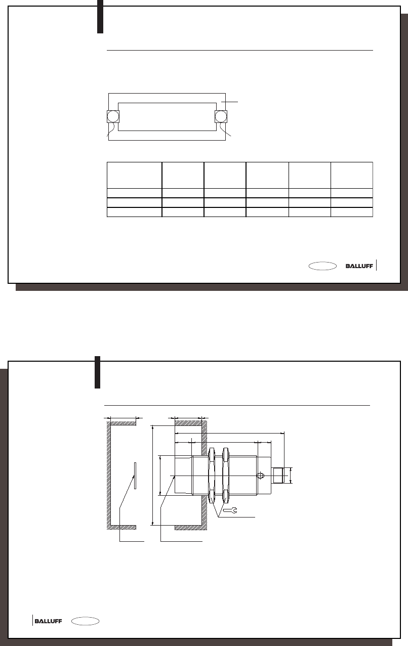
english34
Clear zone a
M30x1.5
Data carrier Active surface
Tightening torque max. 40 Nm
M12x1
36
13
83
50 10
Clear zone c Clear zone b
BIS M-400-007-001-_ _-S115
Installation
Installation and
permissible
distances
35
35
english
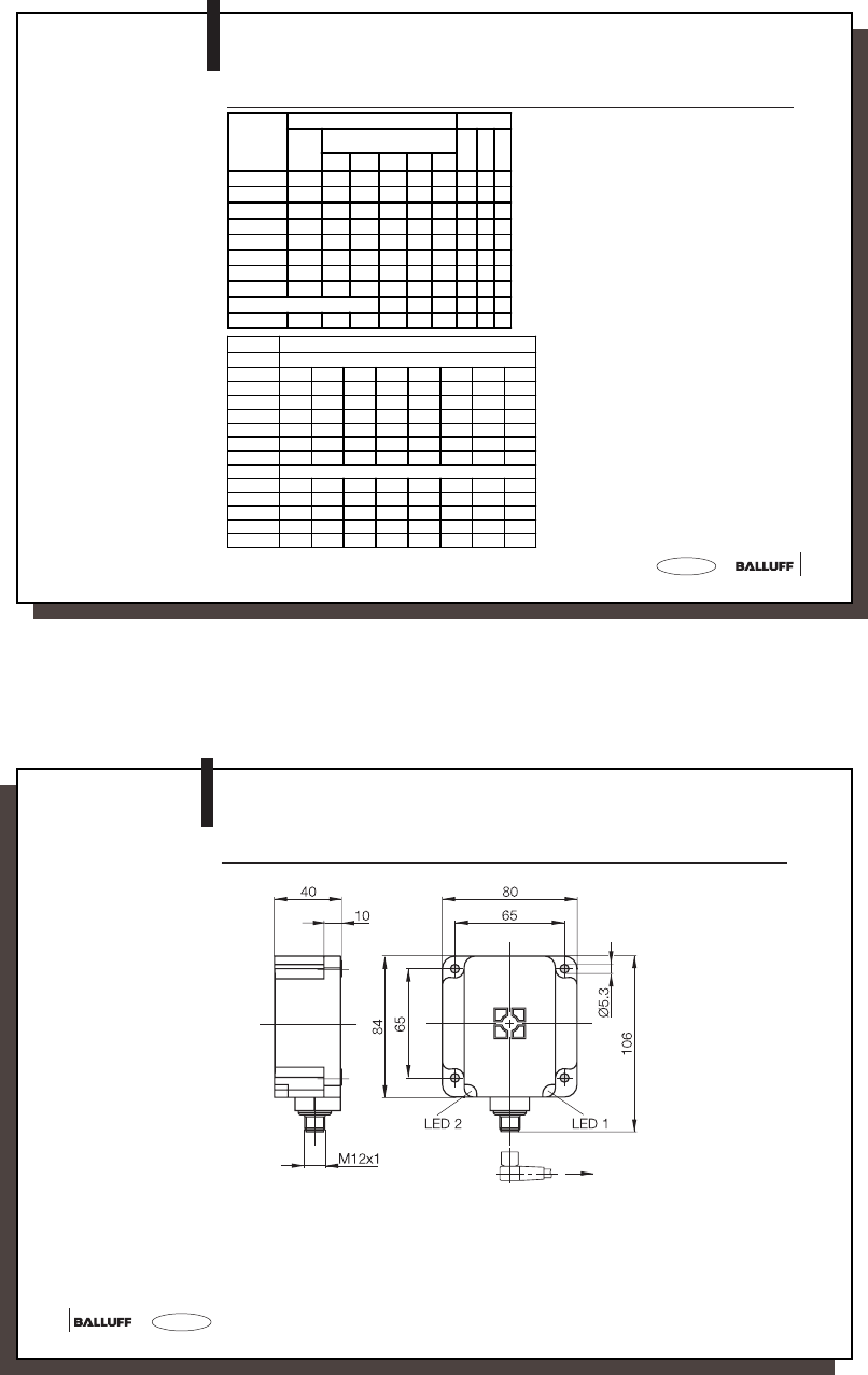
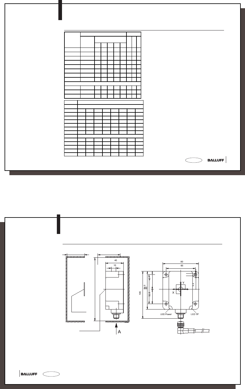
BIS M-400-007-001-_ _-S115
Installation
Characteristic data
by data carrier
Speed in m/s
read
min. di st ance 9 10 3 ,5 3,5 9 8 9 14
DT BIS M-... 101-01/L 102-01/L 105-01/A 105-02/A 108-02/L 110-02/L 111-02/L 112-02/L
ID No. 2.4 3.3 1.25 0.93 1.6 1.33 1.6 2.4
No. of bytes 16 1.65 2.2 0.8 0.55 1 0.76 1 1.3
32 1.5 1.8 0.7 0.42 0.8 0.65 0.8 1
48 1.28 1.58 0.5 0.38 0.6 0.5 0.6 0.86
64 1.1 1.4 0.4 0.3 0.5 0.43 0.5 0.7
write
min. di st ance 9 10 3.5 3.5 9 8 9 14
No. of bytes 16 1.05 1.45 0.52 0.27 0.7 0.5 0.7 0.9
32 0.73 1 .1 0.38 0.19 0.45 0.33 0.45 0.6
48 0.58 0.8 0.2 0.15 0.36 0.23 0.36 0.48
64 0.48 0.65 0.15 0.12 0.28 0.17 0.28 0.38
Characteristic
data by data
carrier (instal led
in clear zone)
at v = 0 (static condition) Clear zone
Dis-
tance
(mm)
Center axis offset at a distance of:
(mm)
abc
515203035
BIS M-101-01/L 0-20 ±14 ±10 ±5 - - 100 30 50
BIS M-102-01/L 0-28 ±20 ±20 ±15 - - 150 30 50
BIS M-105-01/A 0-7 ±7 - - - - 100 20 20
BIS M-105-02/A 0-11 ±8 - - - - 100 20 20
BIS M-108-02/L 0-28 ±16 ±14 ±14 - - 100 30 25
BIS M-110-02/L 0-20 ±12 ±8 ±5 - - 100 30 25
BIS M-111-02/L 0-28 ±16 ±14 ±14 - - 100 30 25
BIS M-112-02/L 0-38 ±22 ±20 ±20 ±16 ±10 150 30 50
(Data carrier is flush installed)
BIS M-108-02/L 0-16 ±10 ±6 - - - 100 30 -
M-4_ _-007-S115_854304_0910_en.p65
36
english36
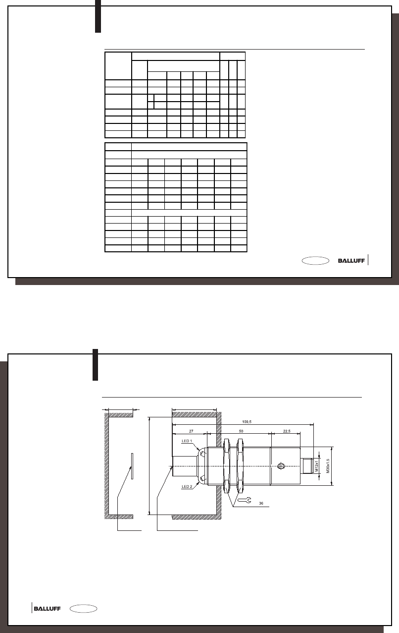
BIS M-401-007-001-_ _-S115
Installation
Installation and
permissible
distances
37
37
english
BIS M-401-007-001-_ _-S115
Installation
Characteristic
data by data
carrier (installed
in clear zone)
at v = 0 (static condition) Clear zone
Dis-
tance
(mm)
Center ax is offset at a distance of:
(mm)
abc
20 30 40 50 60
BIS M-101-01/L0-28±15 ----2007050
BIS M-102-01/L 0-45 ±30 ±24 ±15 - - 200 70 50
BIS M-120-01/L 0 - 50
x ±40 ±40 ±28 ±4 -
250 70 80
y ±30 ±28 ±18 ±4 -
BIS M-108-02/L 0-40 ±25 ±20 ±15 - - 200 50 70
BIS M-110-02/L 0-30 ±20 ±10 - - - 200 50 70
BIS M-111-02/L 0-40 ±25 ±20 ±15 - - 200 50 70
BIS M-112-02/L 20-60 - ±35 ±35 ±25 ±25 200 50 70
Characteristic data
by data carrier
Speed in m/s
rea d
min. distance914151091220
DT BIS M-... 101-01/L 102-01/L 120-01/L 108-02/L 110-02/L 111-02/L 112-02/L
ID No. 4.1 4.5 4.8 3.2 2.6 3.2 4.3
No. of bytes 16 2.7 3.8 4.2 1.88 1.4 1.88 2.6
32 2.28 3 3.9 1.56 1.13 1.56 2.3
48 1.7 6 2.25 3.25 1.2 5 0.85 1.2 5 1.8
64 1.5 1.9 3 0.98 0.65 0.98 1.5
write
min. distance914151091220
No. of bytes 16 1.5 5 2.2 3.1 1.25 0.8 5 1.2 5 1.65
32 1.3 4 1.78 2.2 5 0.84 0.5 5 0.84 1.08
48 1 1.3 1.7 5 0.7 0.3 8 0.7 0.8 8
64 0.9 3 1 1.5 3 0.5 0.25 0.5 0.78
M-4_ _-007-S115_854304_0910_en.p65
38
english38
BIS M-400-007-002-_ _-S115
Installation
Installation and
permissible
distances
Clear zone a
Data carrier Active surface
Tightening torque
max. 40 Nm
Clear zone c Clear zone b
39
39
english
Characteristic data
by data carrier
Characteristic
data by data
carrier (installed
in clear zone)
at v = 0 (static condition) Clear zone
Distance
(mm) read/
write
Center axis offset at a distance of:
(mm)
abc
5 10152025
BIS M-101-01/ L 0-15 ±9 ±6 ±4 - - 10 0 30 25
BIS M-102-01/ L 0-18 ±16 ±12 ±8 - - 15 0 30 50
BIS M-105-01/A 0-6 ±4----1002010
BIS M-105-02/A 0-9 ±6----1002010
BIS M-108-02/ L 0-20 ±14 ±12 ±10 ±7 - 100 30 25
BIS M-110-02/ L 0-15 ±8 ±6 ±4 - - 10 0 30 25
BIS M-111-02/ L 0-20 ±12 ±10 ±10 - - 10 0 30 25
BIS M-112-02/ L 0-28 ±20 ±18 ±18 ±16 ±12 150 30 50
(Data carrier is flush installed)
BIS M-105-01/A 0-5 ±2----10020-
BIS M-105-02/A 0-5 ±2----10020-
BIS M-108-02/ L 0-12 ±8 ±6 - - - 10 0 30 -
Speed in m/s
read
min. distance673,53,56568
DT BIS M-... 101-01/L 102-01/L 105-01/A 105-02/A 108-02/L 110-02/L 111-02/L 112-02/L
ID No. 2 2.6 0.85 0.6 1.3 1 1.3 1.8
No. of bytes 16 1.3 2 0.54 0.38 0.87 0.7 0.87 1.15
32 1 1.75 0.48 0.28 0.66 0.5 0.66 1
48 0.88 1.4 0.38 0.21 0.52 0.4 0.52 0.88
64 0.78 1.3 0.33 0.17 0.48 0.3 0.48 0.73
writ e
min. distance673.53.56568
No. of bytes 16 0.9 1.38 0.38 0.25 0.51 0.38 0.51 0.82
32 0.62 1.05 0.24 0.11 0.33 0.25 0.33 0.58
48 0.44 0.78 0.19 0.08 0.27 0.18 0.27 0.4
64 0.38 0.62 0.11 - 0.2 0.15 0.2 0.32
BIS M-400-007-002-_ _-S115
Installation
M-4_ _-007-S115_854304_0910_en.p65
40
english40
Installation and
permissible
distances
BIS M-451-007-001-_ _-S115
Installation
Data carrier
Clear zone a
Active surface
Clear zone c Clear zone b
41
41
english
BIS M-451-007-001-_ _-S115
Installation
Characteristic data
by data carrier Characteristic
data by data
carrier (installed
in clear zone)
at v = 0 (static condition) Clear zone
Distance
(mm) read/
write
X-axis offset at a distance
of: (mm)
Y-axis offset at a distance
of: (mm)
abc
0...10 25 40 50 0...10 25 40 50
BIS M-150-02/A 0-60 ±50 ±40 ±30 ±10 ±10 ±10 ±8 ±5 200 70 0
BIS M-151-02/A 0-60 ±50 ±40 ±30 ±10 ±10 ±10 ±8 ±5 200 70 0
(in air)
BIS M-150-02/A 0-40 ±40 ±30 ±10 - ±10 ±8 ±5 - 200 70 -
BIS M-151-02/A 0-5 ±40 ±30 ±10 - ±10 ±8 ±5 - 100 20 -
M-4_ _-007-S115_854304_0910_en.p65
42
english42
BIS M-4_ _-007-_ _ _-00-S115
Installation
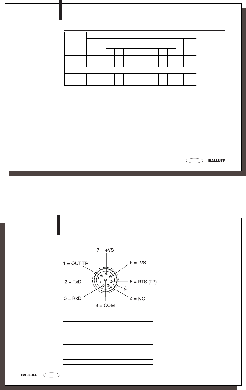
Pin assignments
BIS M-4_ _-007-...
-00-S115
RS232 = 00 Color code using cables
BKS-S116-PU / -S115-PU
1 OUT TP yellow
2TxD gray
3RxD pink
4NC red
5 RTS (TP) green
6-VS blue
7+VS brown
8COM white
43
43
english
BIS M-4_ _-007-_ _ _-00-S115
Interface Information
Interface
V.24 / RS232
➀ RTS connection (TP) allows TP display in the BISCOMRW.EXE program.
➁ OUT TP switches to +24V when there is a data carrier in the capture zone.
9 pin connector
M-4_ _-007-...-00-S115
M-4_ _-007-S115_854304_0910_en.p65
44
english44
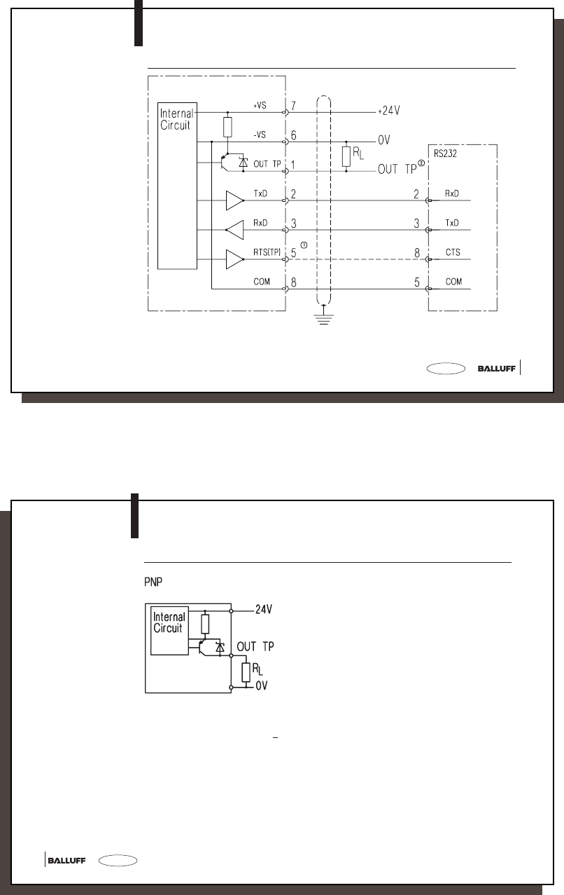
BIS M-4_ _-007-_ _ _-00-S115
Connection Diagrams
Wiring the outputs
OUT TP (only for
RS232)
Supply voltage: DC 24 V +10% / –20% (incl. ripple)
Output current: max. 200 mA
Voltage drop at 50 mA: < 1.5 V
45
45
english
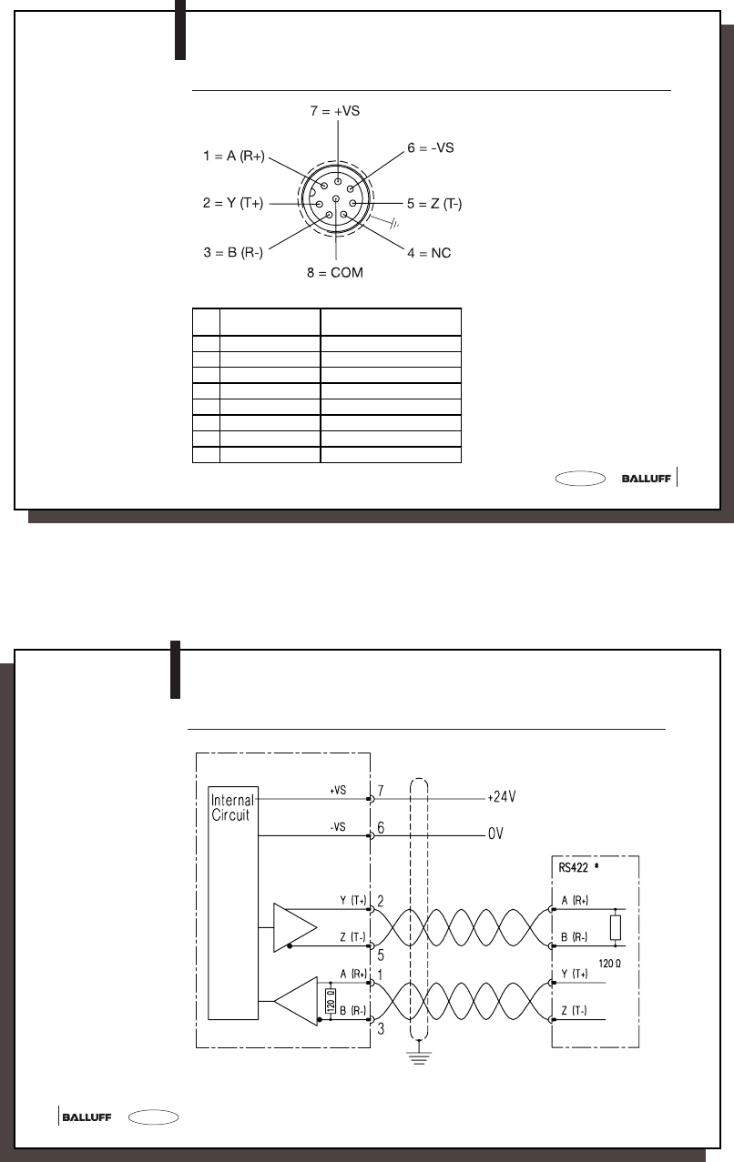
BIS M-4_ _-007-_ _ _-02-S115
Installation
Pin assignments
BIS M-4_ _-007-...
-02-S115
RS422 = 00 Color code using cables
BKS-S116-PU / -S115-PU
1 OUT TP yellow
2TxD gray
3RxD pink
4NC red
5 RTS (TP) green
6-VS blue
7+VS brown
8COM white
M-4_ _-007-S115_854304_0910_en.p65
46
english46
Interface
RS422
4-wires
point-to-point
BIS M-4_ _-007-_ _ _-02-S115
Interface Information
M-4_ _-007-...-02-S115
* For the power supply and the RS422 interface a galvanic isolation is recommended!
Twisted pair cable data links.
1) Termination
1)
47
47
english
BIS M-4_ _
Technical Data
General data Housing M-400-... M-401-...
CuZn nickel-plated plastic (PBT)
Ambient temperature 0 °C to +70 °C
Enclosure rating IP 67
Supply voltage VSDC 24 V +10 % / –20 % (incl. ripple)
LPS Class 2
Current consumption ≤ 50 mA with no load
Power LED green
Tag Present (TP) LED yellow
Temperature range
Enclosure rating
Supply voltage
LED function
indicator
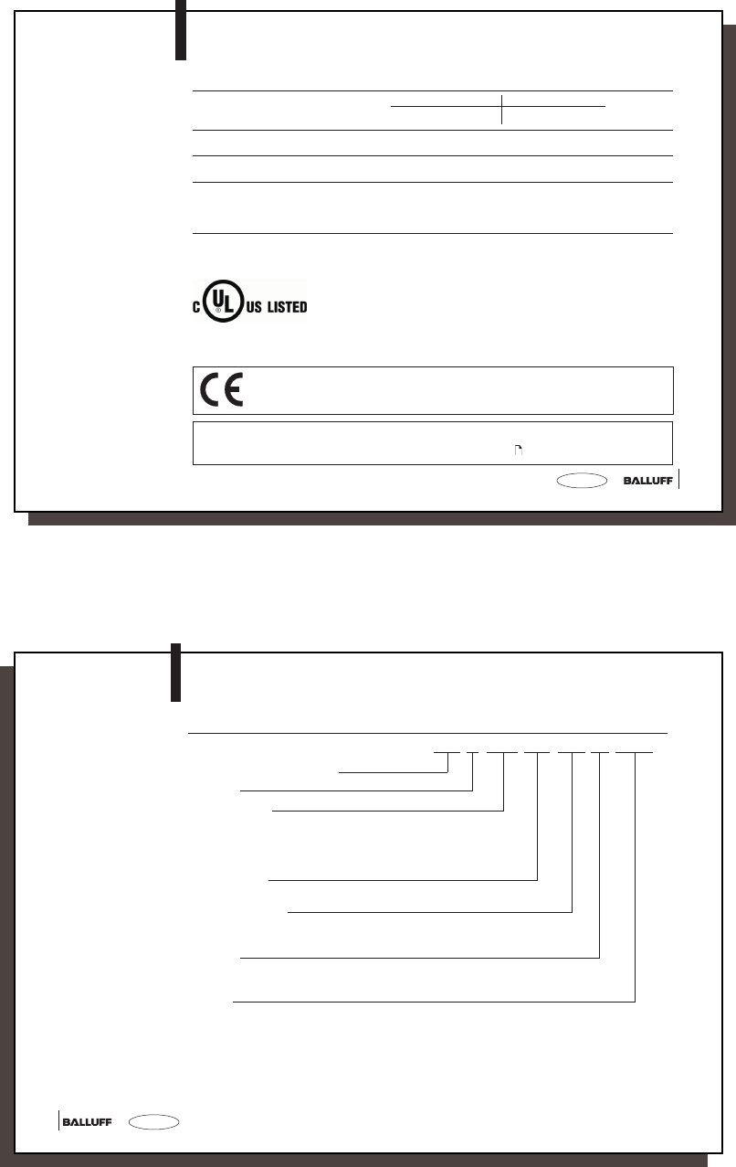
This product was developed and produced considering the claimed
European standards and guidelines.
Control No 3TLJ
File No E227256
Process Control Equipment
CE Declaration of
Conformity and
user safety
☞You can separately request a Declaration of Conformity.
Further safety measures you can find in chapter Safety (see 4).
M-4_ _-007-S115_854304_0910_en.p65
48
english48
BIS M-4_ _
Ordering Information
Part Numbers
Balluff Identification System
Series M
Hardware type
4_ _ = Processor
400 = M30 housing
401 = Maxisensor
451 = Maxisensor for data carrier on metal
Software type
007 = Balluff-Protocol
Hardware version
001 = Coil
002 = M18 read/write head
Interface
00 = RS232
02 = RS422 (4-wires, point-to-point)
Module
S115 = M12 8-pole female
BIS M-4_ _-007-00_-0_-S115
49
49
english
BIS M-4_ _
Ordering Information
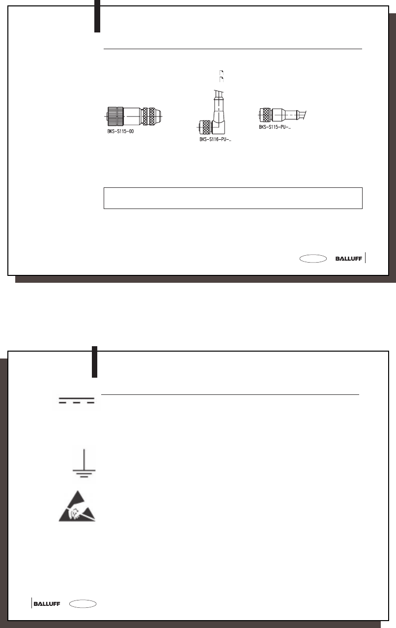
Accessories
(optional, not
included in scope of
delivery)
Type Part No.
Mating connector without cable BKS-S115-00
Cable (Pin assignments see 40) BKS-S116-PU-..
Cable (Pin assignments see 40) BKS-S115-PU-..
Cable is available in various standard lengths:
2 m, 5 m, 10 m, 15 m, 20 m, 25 m
Example: BKS-S115-PU-02 Part number for 2 m cable
BKS-S116-PU-15 Part number for 15 m cable
For BIS M-4_ _-007-00_-0_-S115 and a baud rate of 19.200 cable length max. 15 m
9.600 cable length max. 20 m
☞
M-4_ _-007-S115_854304_0910_en.p65
50
english50
Symbols / Abbreviations
DC Current
Limited Power Source Class 2
Function ground
ESD Symbol
LPS

51
51
english
Appendix, ASCII Table
Deci-
mal Hex Control
Code ASCII Deci-
mal Hex Control
Code ASCII Deci-
mal Hex ASCII Deci-
mal Hex ASCII Deci-
mal Hex ASCII Deci-
mal Hex ASCII
0 00 Ctrl @ NUL 22 16 Ctrl V SYN 44 2C , 65 41 A 86 56 V 107 6B k
1 01 Ctrl A SOH 23 17 Ctrl W ETB 45 2D - 66 42 B 87 57 W 108 6C l
2 02 Ctrl B STX 24 18 Ctrl X CAN 46 2E . 67 43 C 88 58 X 109 6D m
3 03 Ctrl C ETX 25 19 Ctrl Y EM 47 2F / 68 44 D 89 59 Y 110 6E n
4 04 Ctrl D EOT 26 1A Ctrl Z SUB 48 30 0 69 45 E 90 5A Z 111 6F o
5 05 Ctrl E ENQ 27 1B Ctrl [ ESC 49 31 1 70 46 F 91 5B [ 112 70 p
6 06 Ctrl F ACK 28 1C Ctrl \ FS 50 32 2 71 47 G 92 5C \ 113 71 q
7 07 Ctrl G BEL 29 1D Ctrl ] GS 51 33 3 72 48 H 93 5D ] 114 72 r
8 08 Ctrl H BS 30 1E Ctrl ^ RS 52 34 4 73 49 I 94 5E ^ 115 73 s
9 09 Ctrl I HT 31 1F Ctrl _ US 53 35 5 74 4A J 95 5F _ 116 74 t
10 0A Ctrl J LF 32 20 SP 54 36 6 75 4B K 96 60 ` 117 75 u
11 0B Ctrl K VT 33 21 ! 55 37 7 76 4C L 97 61 a 118 76 v
12 0C Ctrl L FF 34 22 " 56 38 8 77 4D M 98 62 b 119 77 w
13 0D Ctrl M CR 35 23 # 57 39 9 78 4E N 99 63 c 120 78 x
14 0E Ctrl N SO 36 24 $ 58 3A : 79 4F O 100 64 d 121 79 y
15 0F Ctrl O SI 37 25 % 59 3B ; 80 50 P 101 65 e 122 7A z
16 10 Ctrl P DLE 38 26 & 60 3C < 81 51 Q 102 66 f 123 7B {
17 11 Ctrl Q DC1 39 27 ' 61 3D = 82 52 R 103 67 g 124 7C |
18 12 Ctrl R DC2 40 28 ( 62 3E > 83 53 S 104 68 h 125 7D }
19 13 Ctrl S DC3 41 29 ) 63 3F ? 84 54 T 105 69 i 126 7E ~
20 14 Ctrl T DC4 42 2A * 64 40 @ 85 55 U 106 6A j 127 7F DEL
21 15 Ctrl U NAK 43 2B +
M-4_ _-007-S115_854304_0910_en.p65