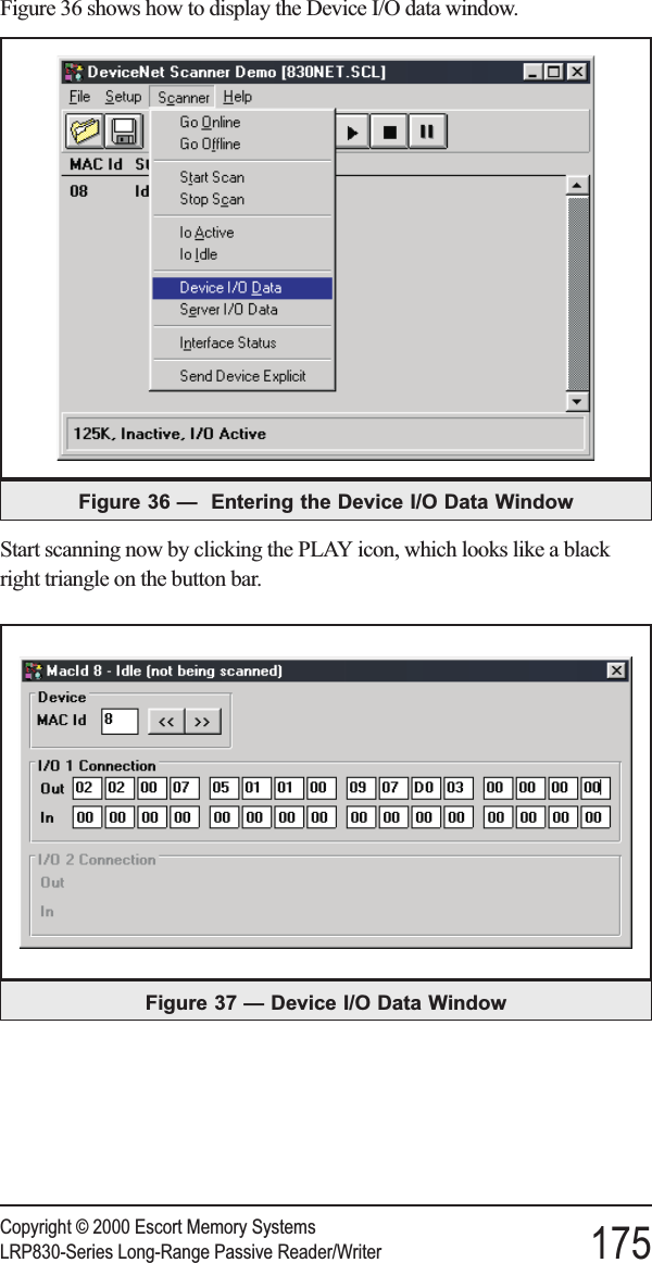
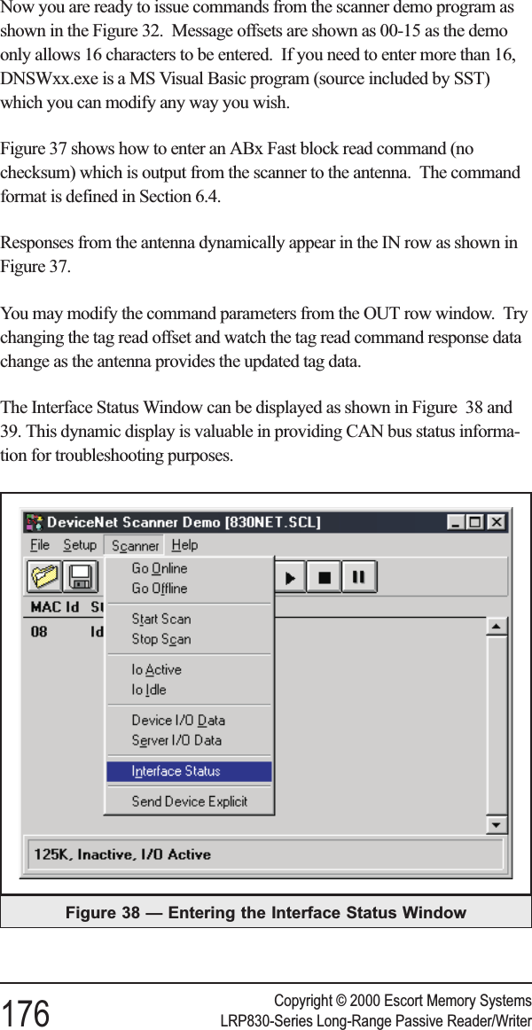
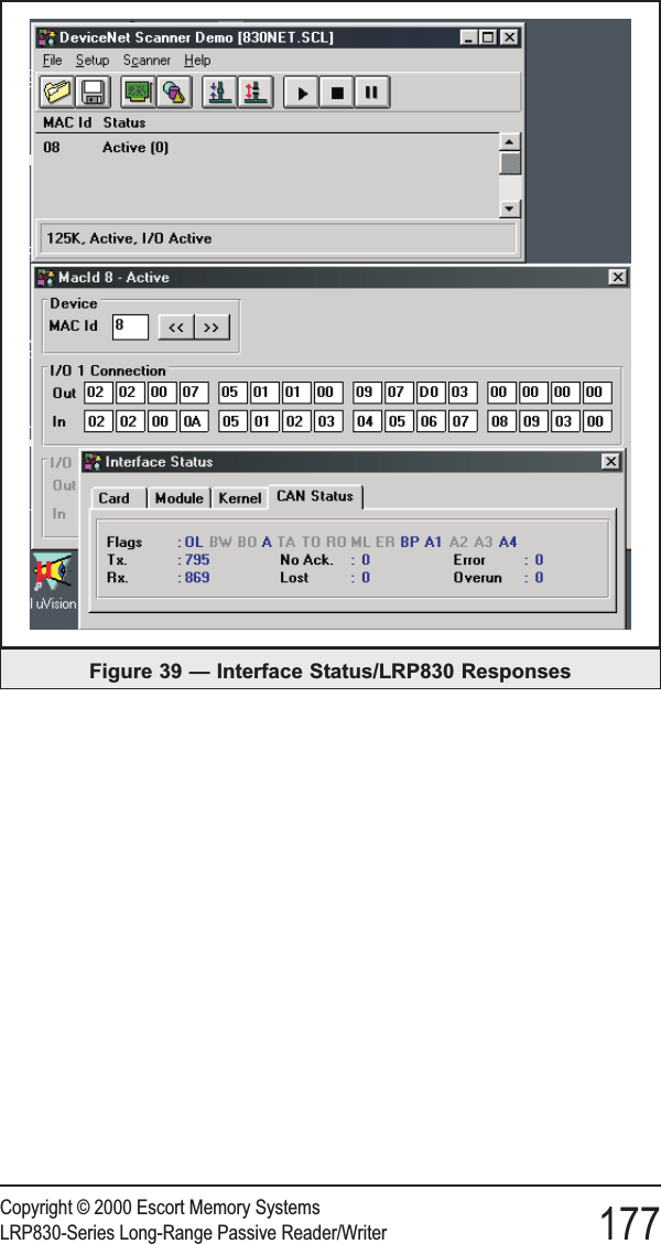
Balluff LRP800 Passive Tag Reader LRP820/LRP830 User Manual C transfer 1271 LRP830 vp
BALLUFF inc Passive Tag Reader LRP820/LRP830 C transfer 1271 LRP830 vp
Balluff >
Contents
- 1. User Manual Lrp820
- 2. User Manual Lrp830
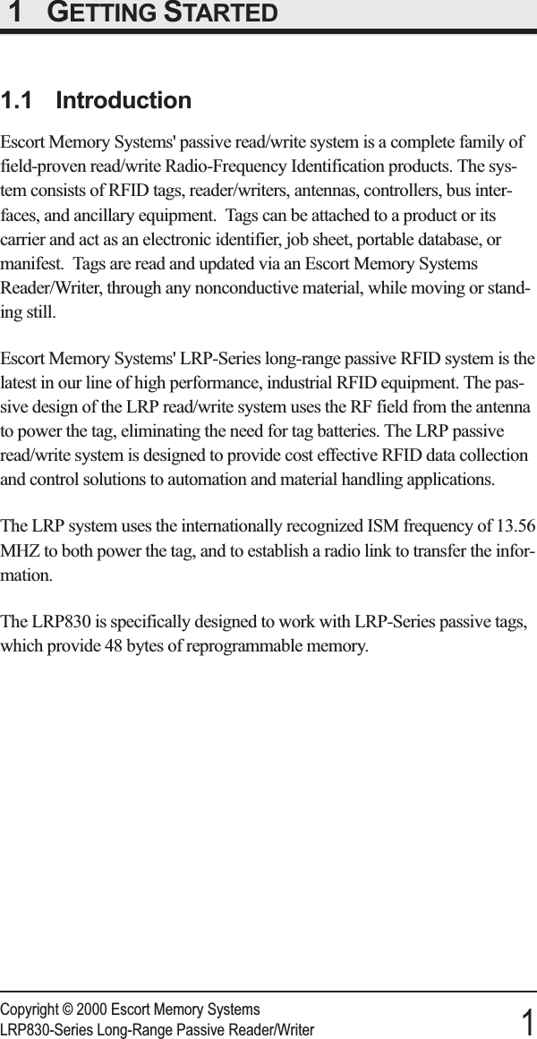
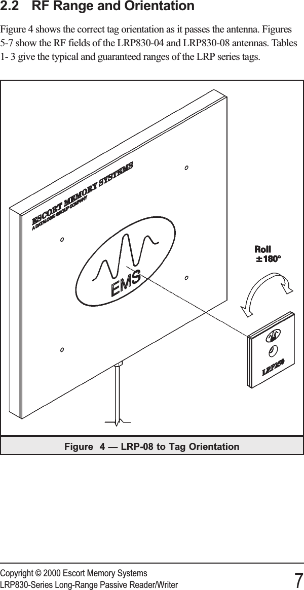
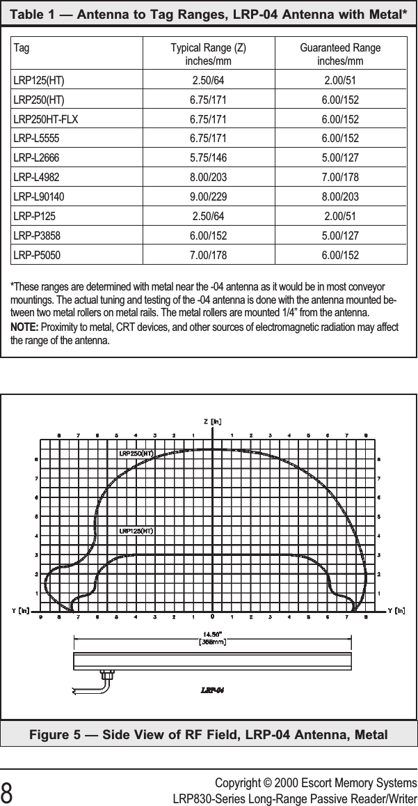
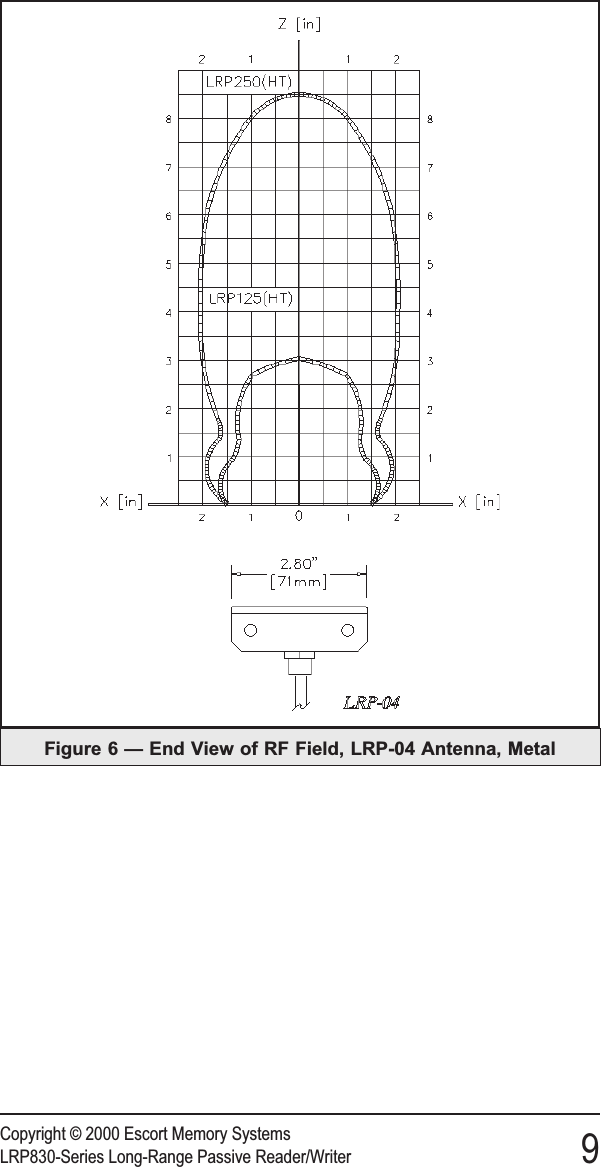
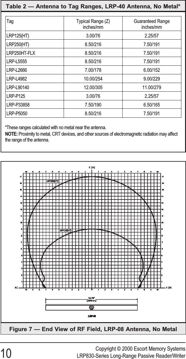
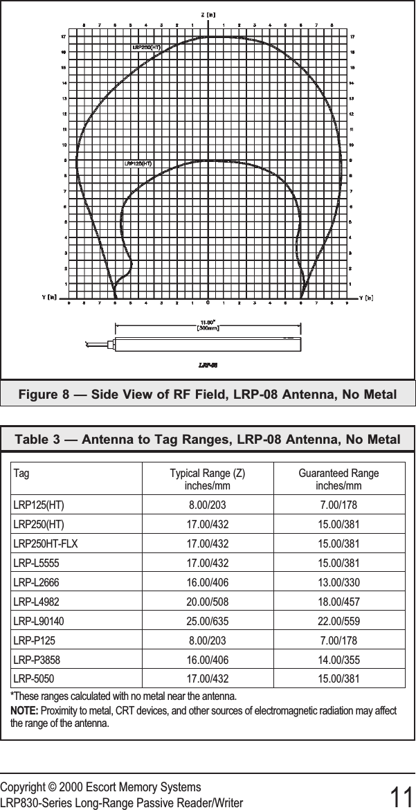
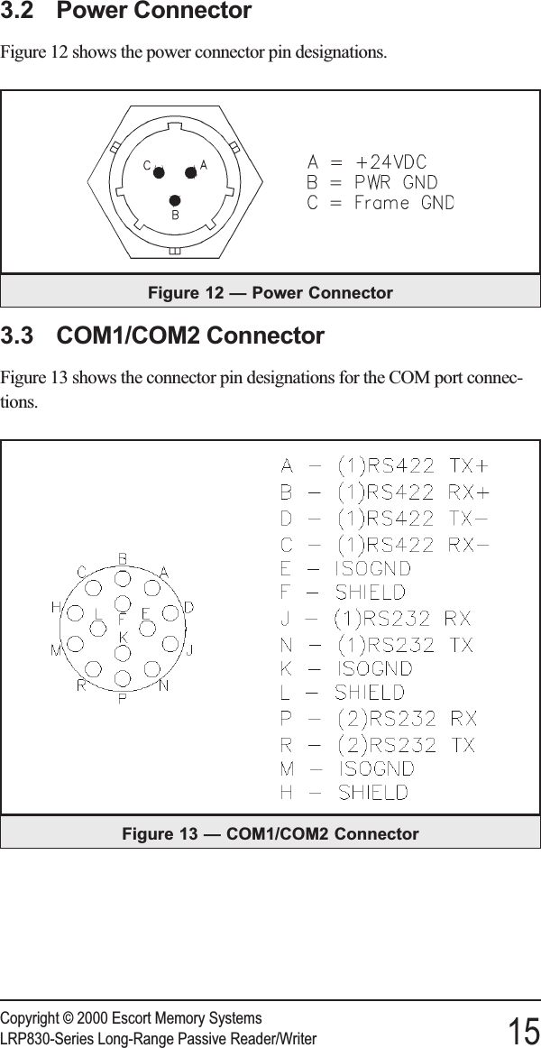
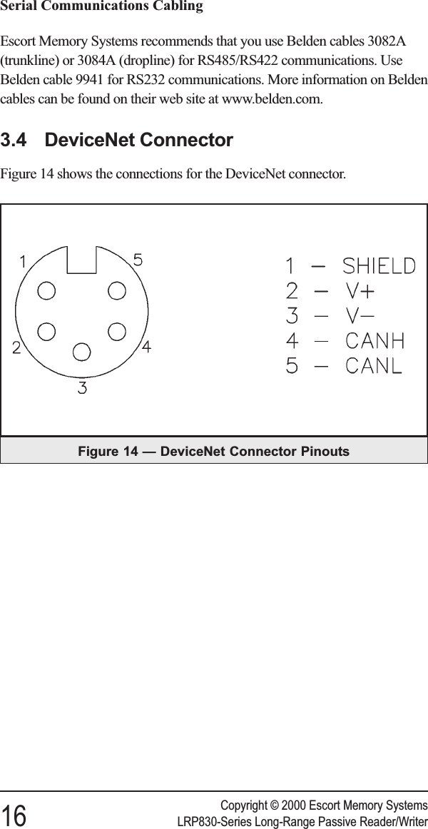
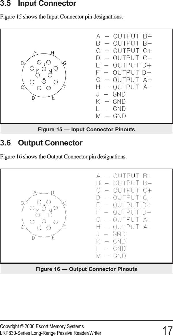
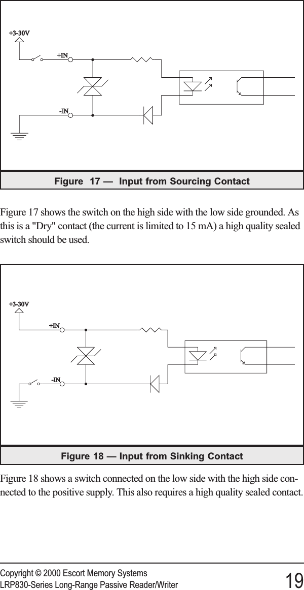
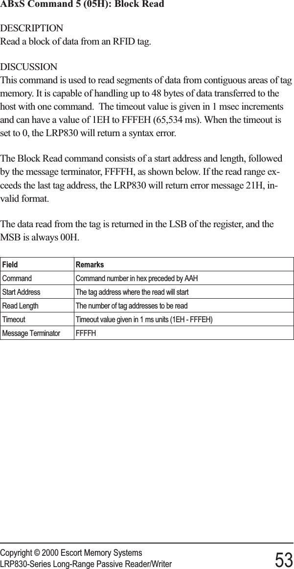
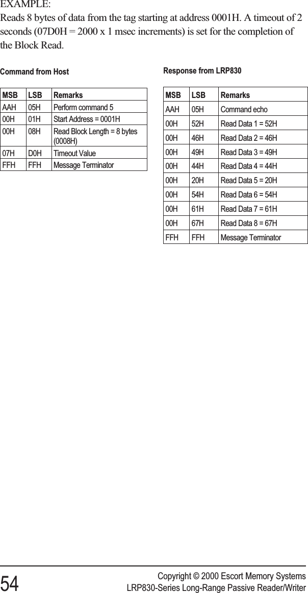
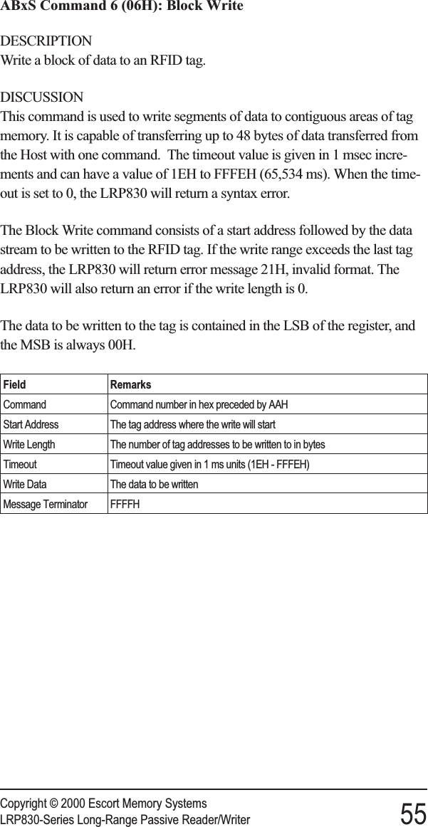
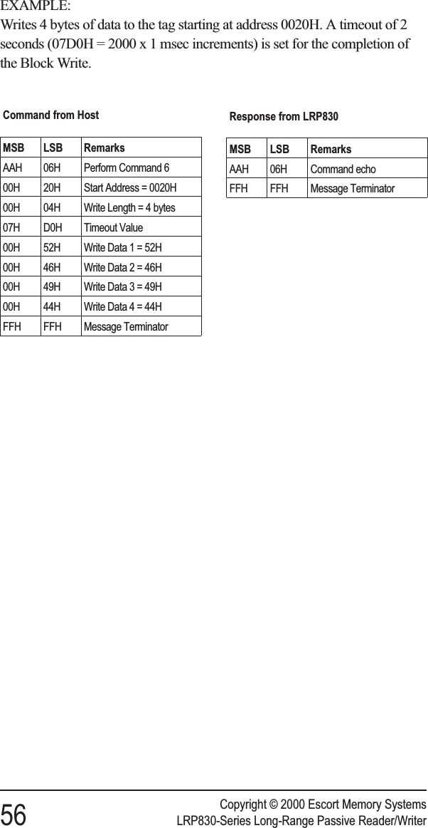
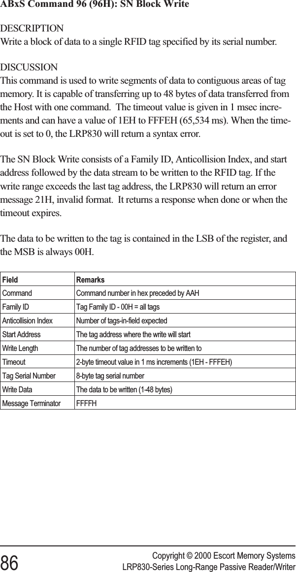
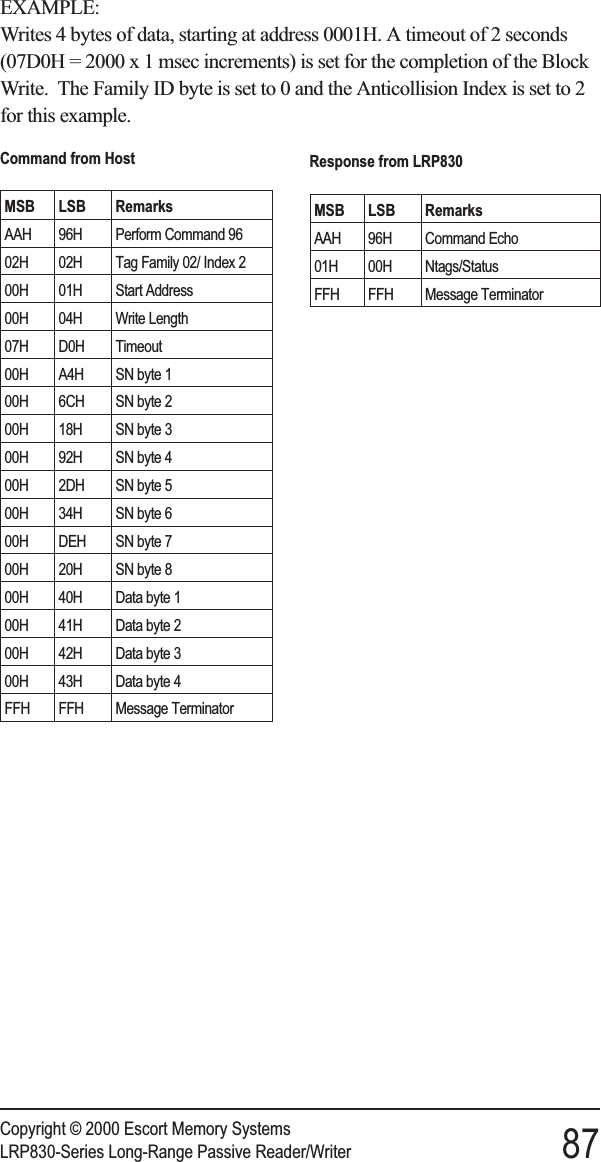
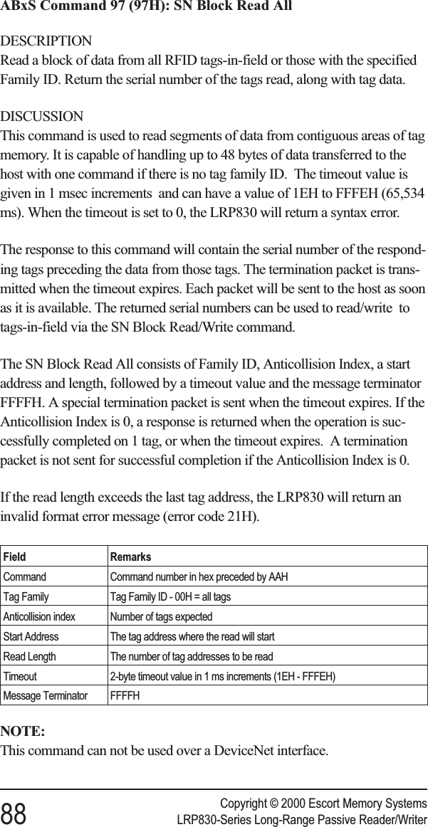
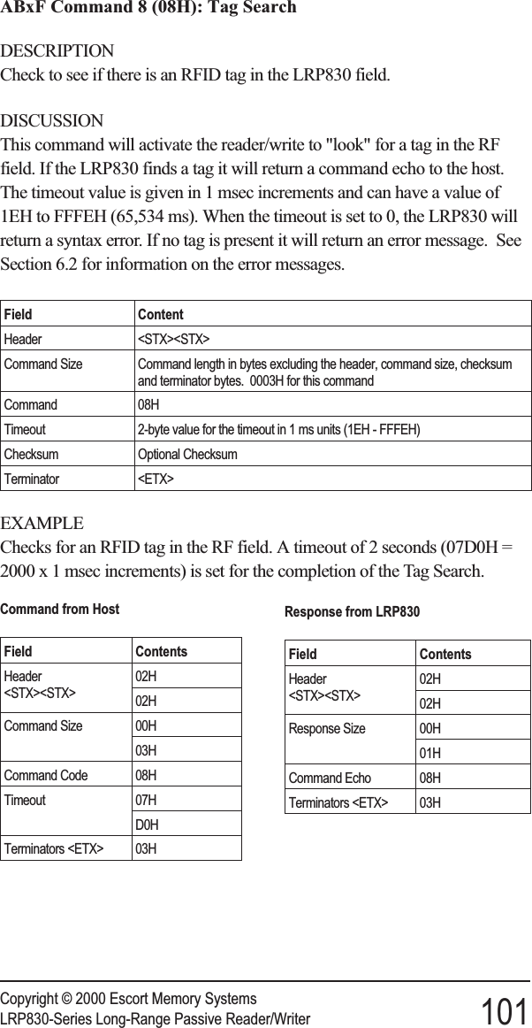
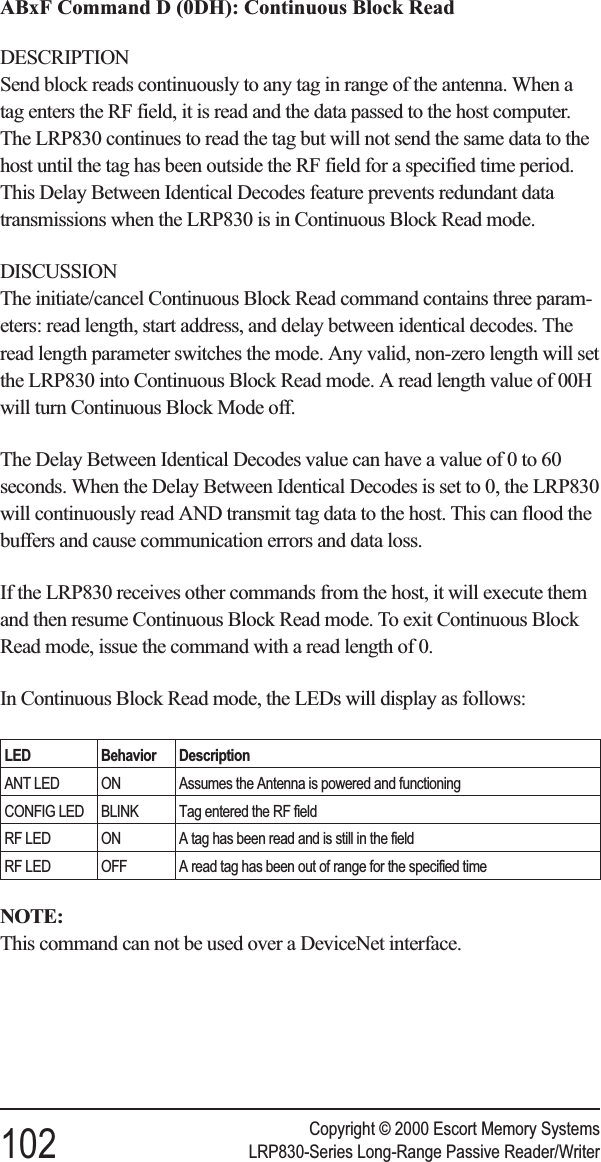
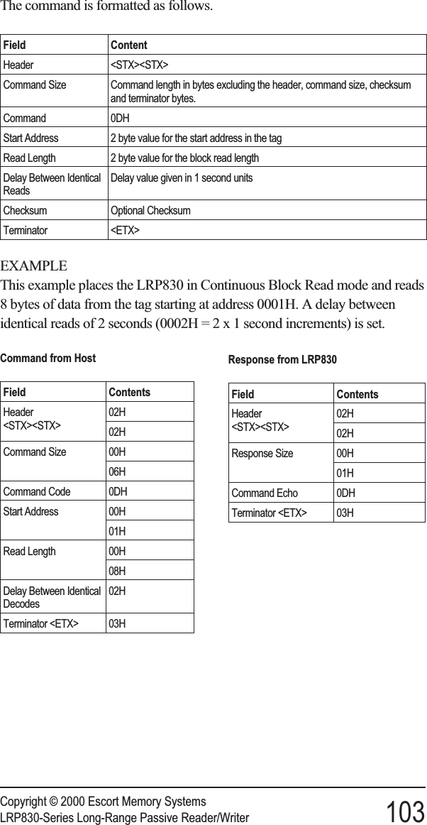
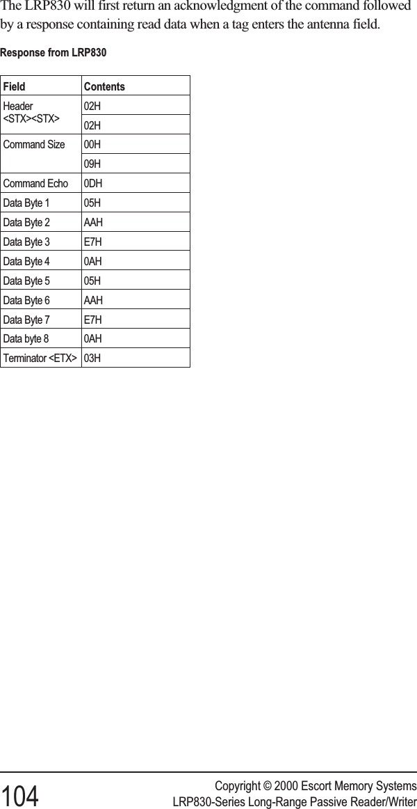
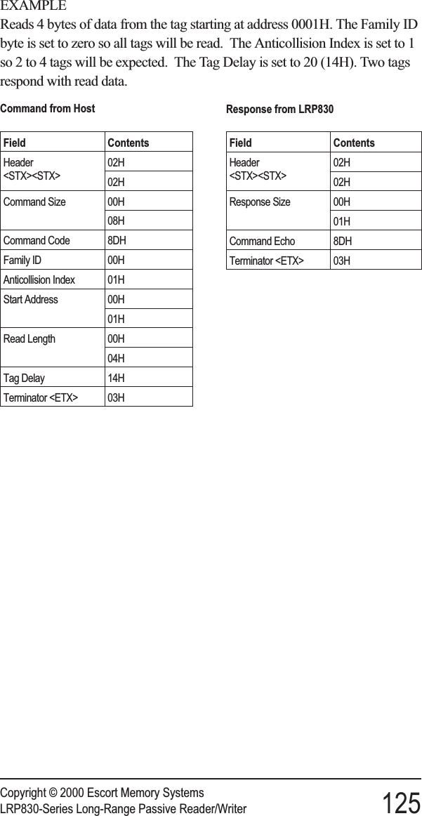
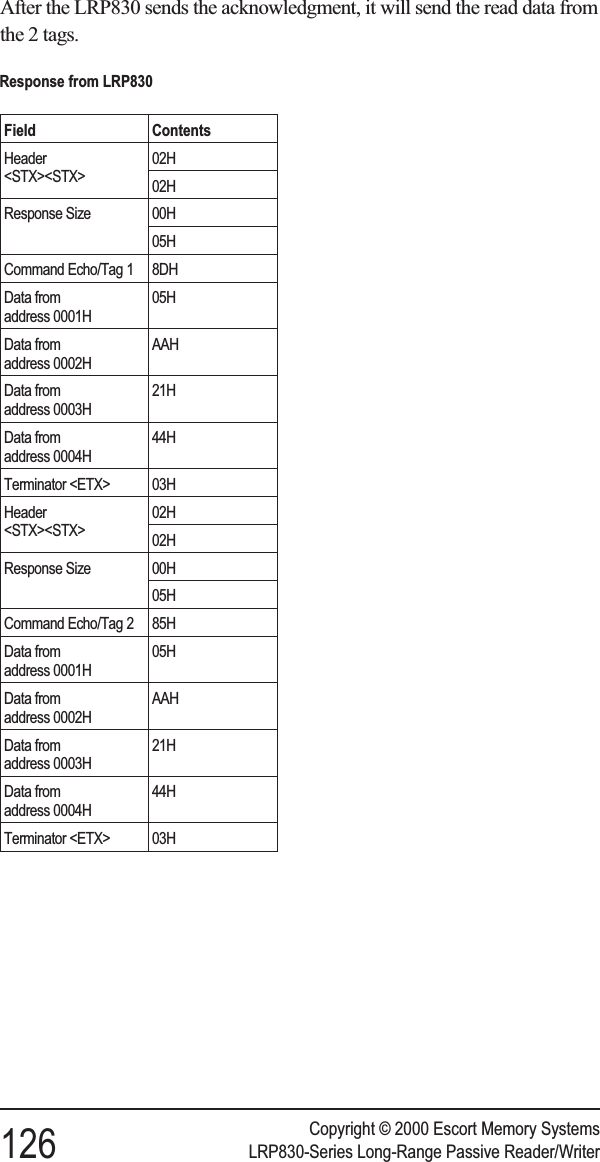
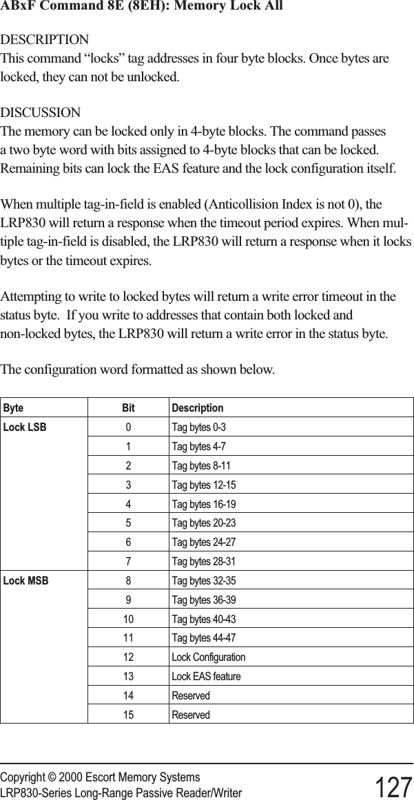
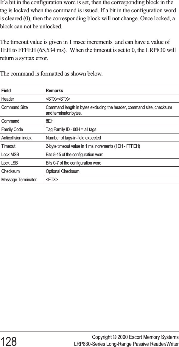
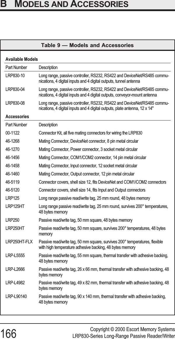
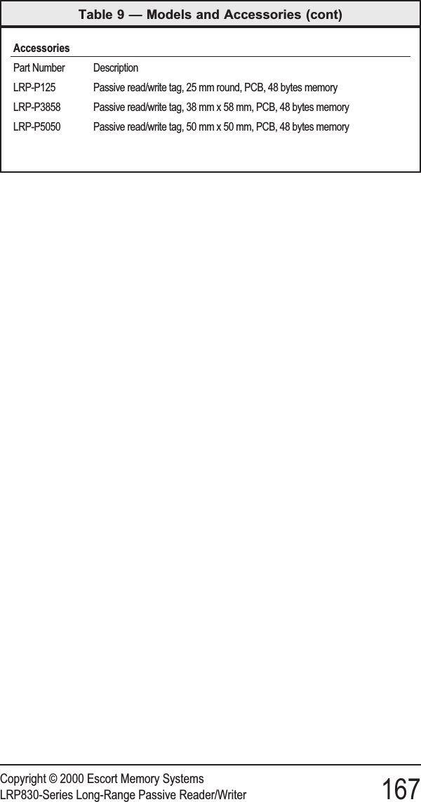
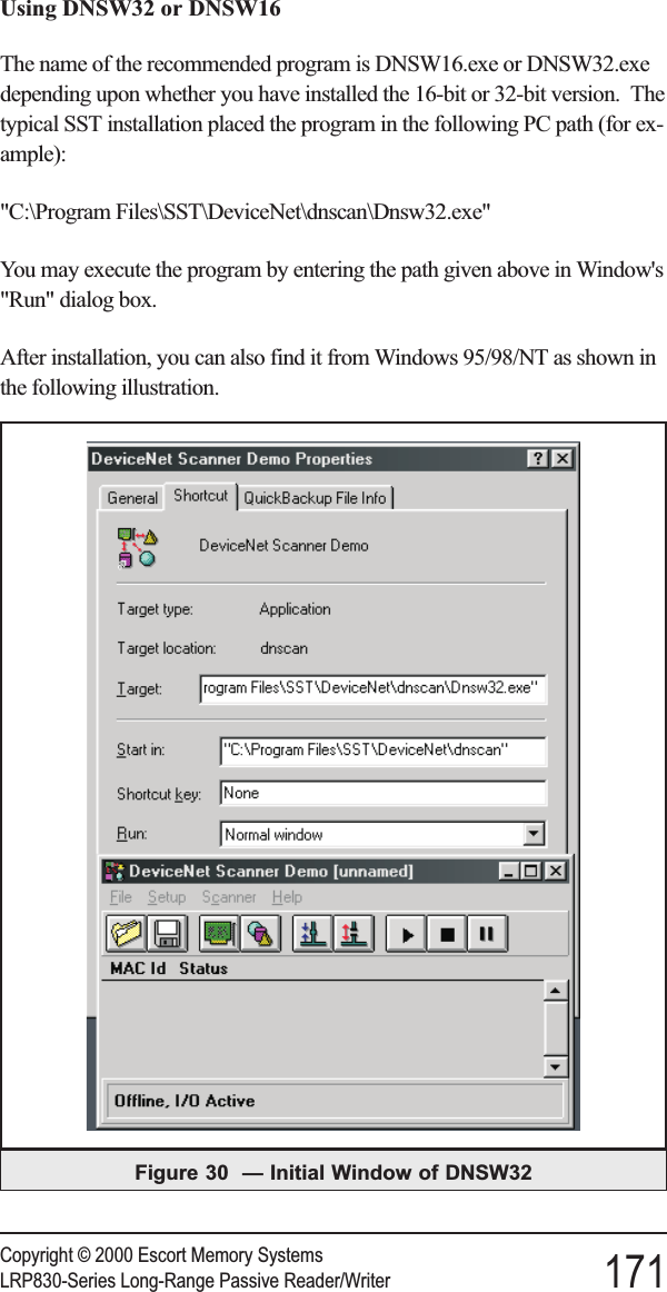
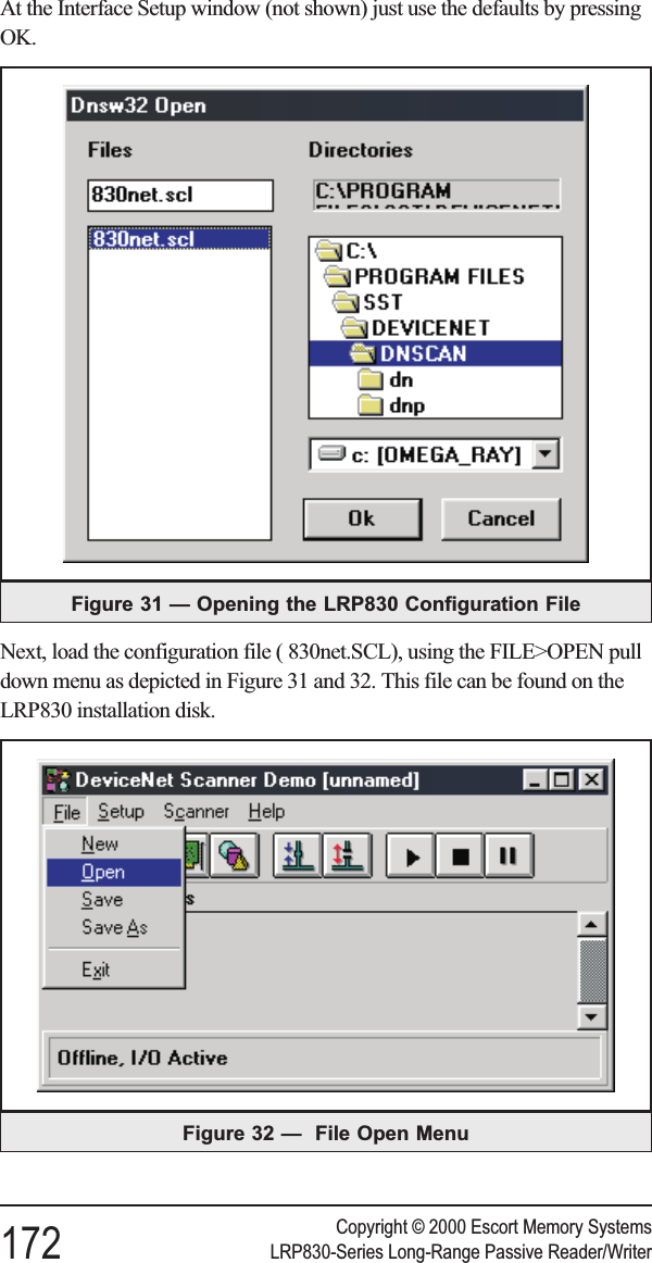
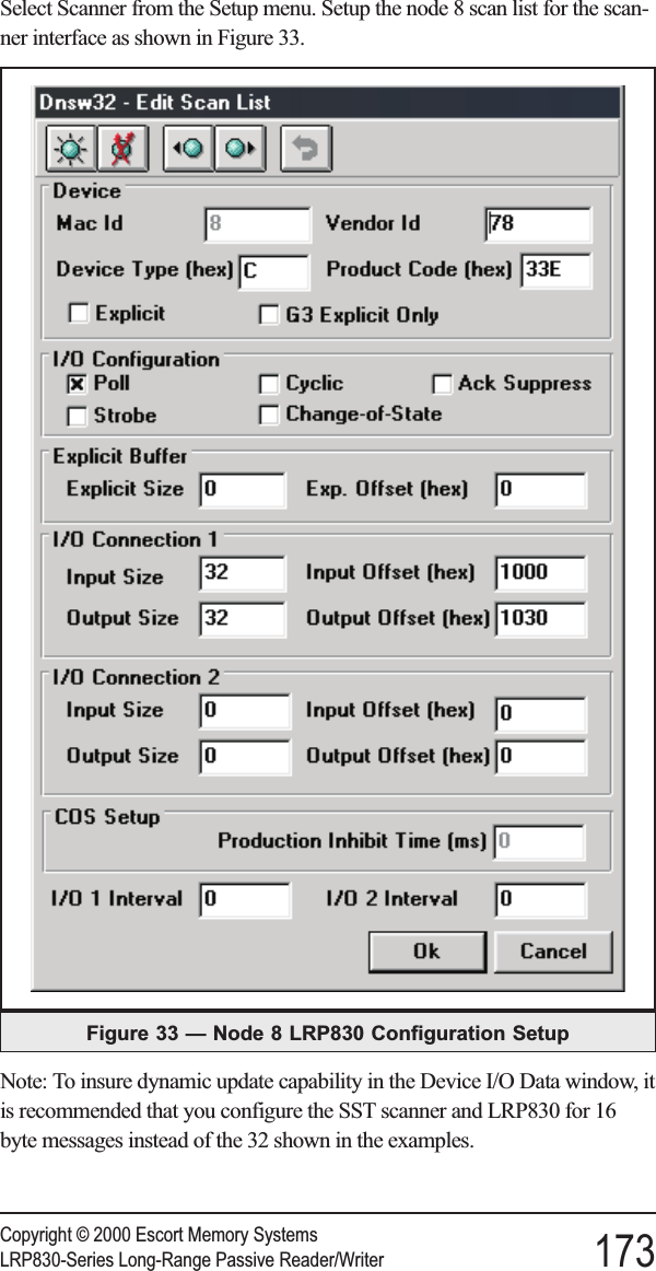
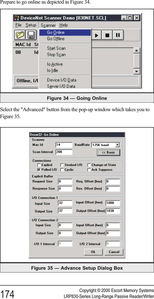
User Manual Lrp830

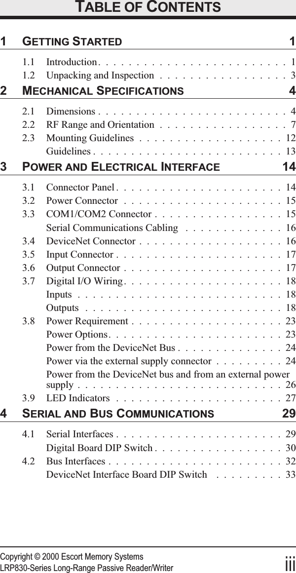

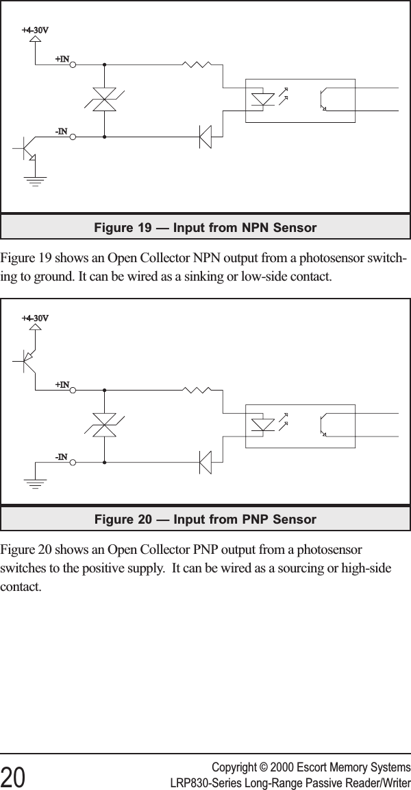
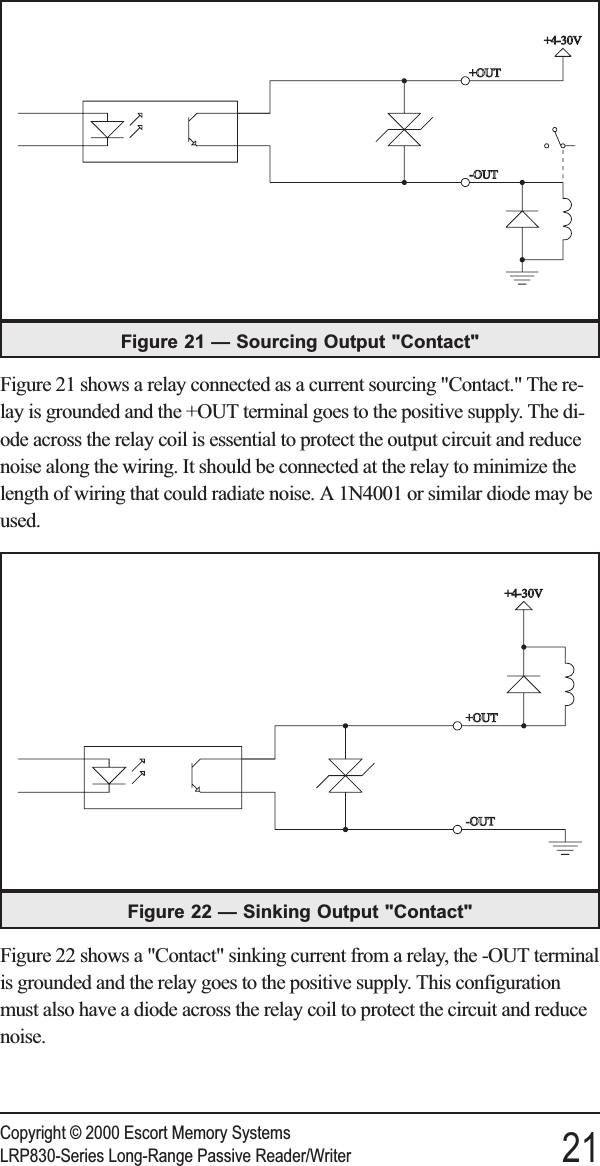
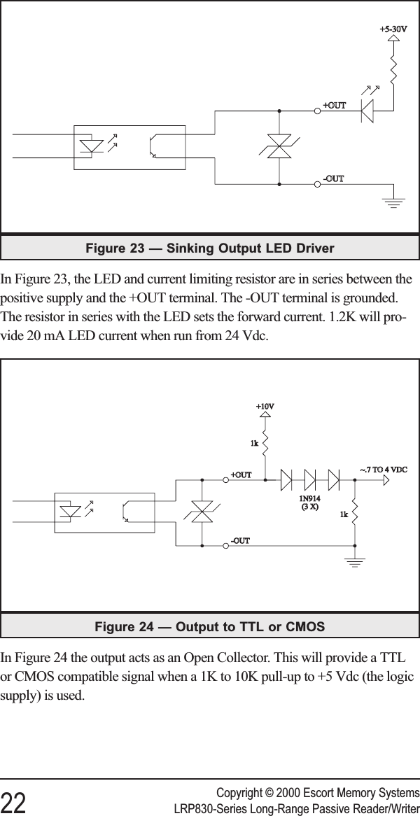
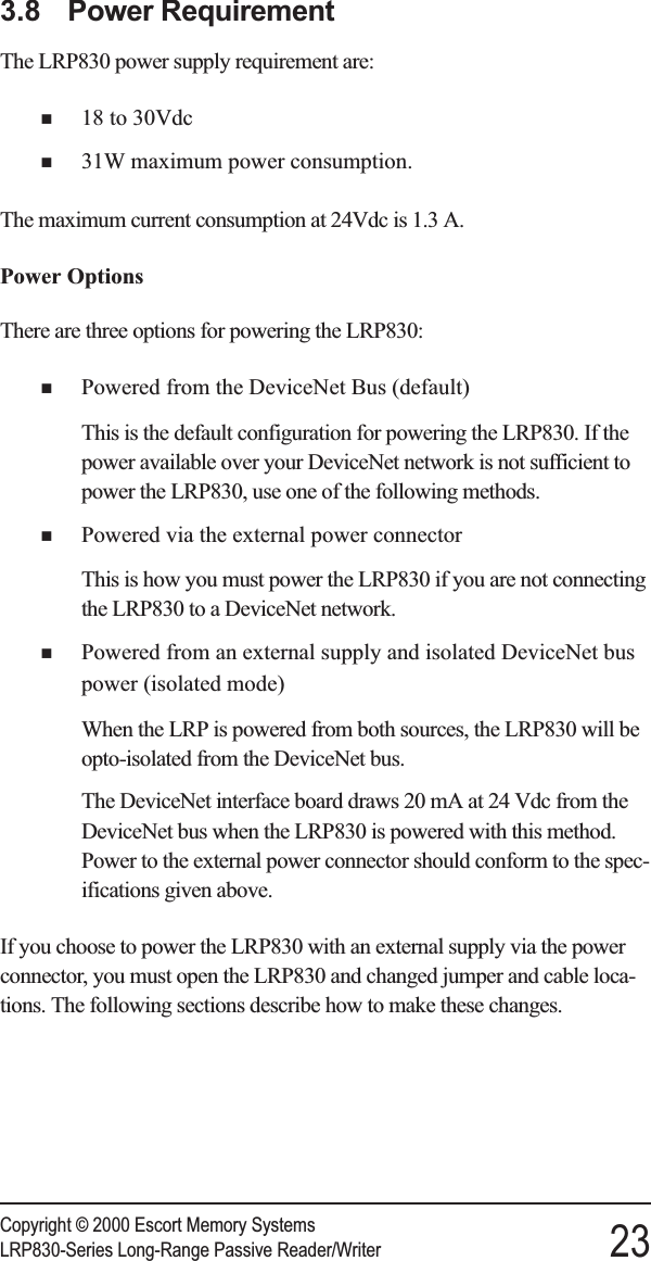

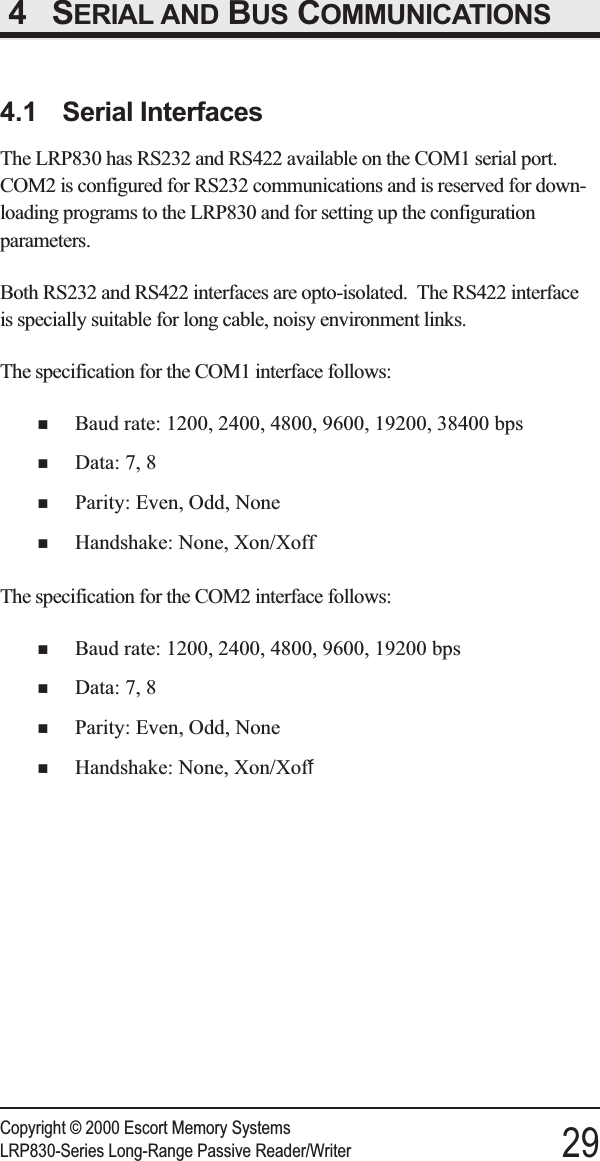
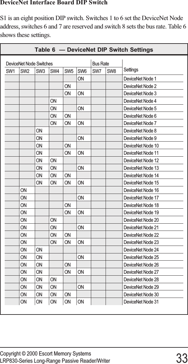
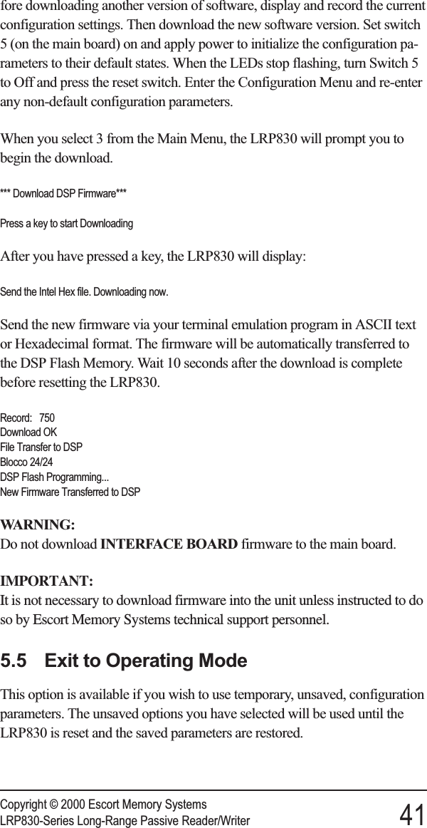
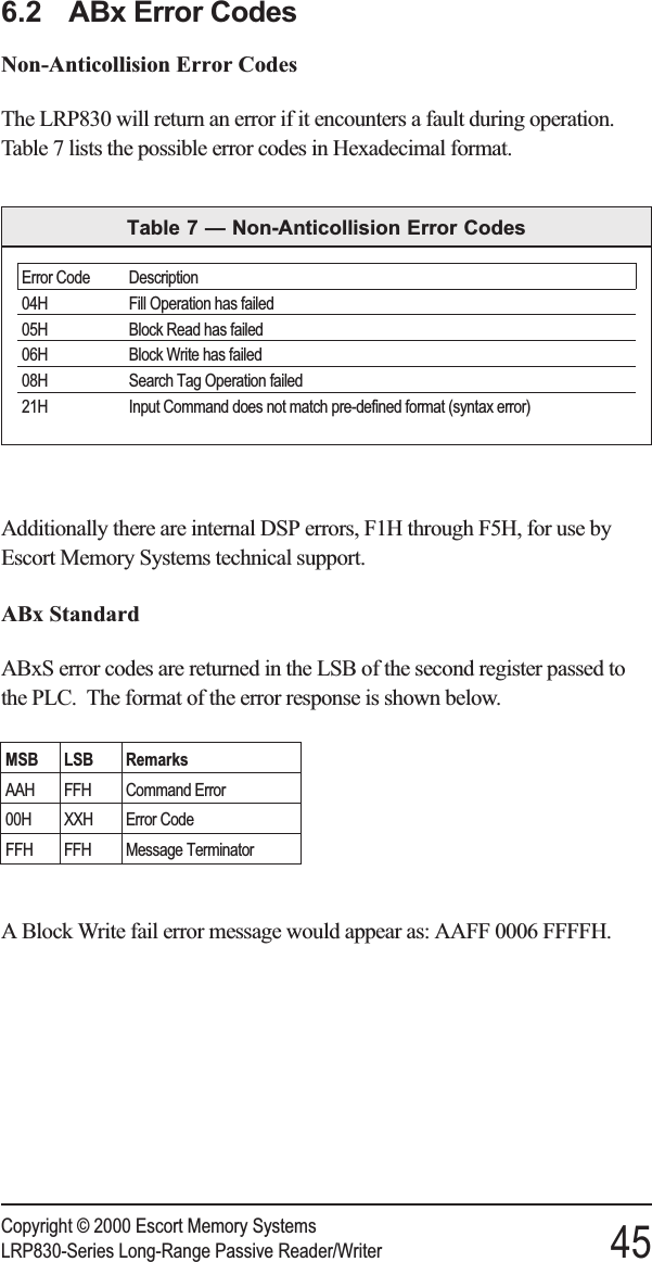
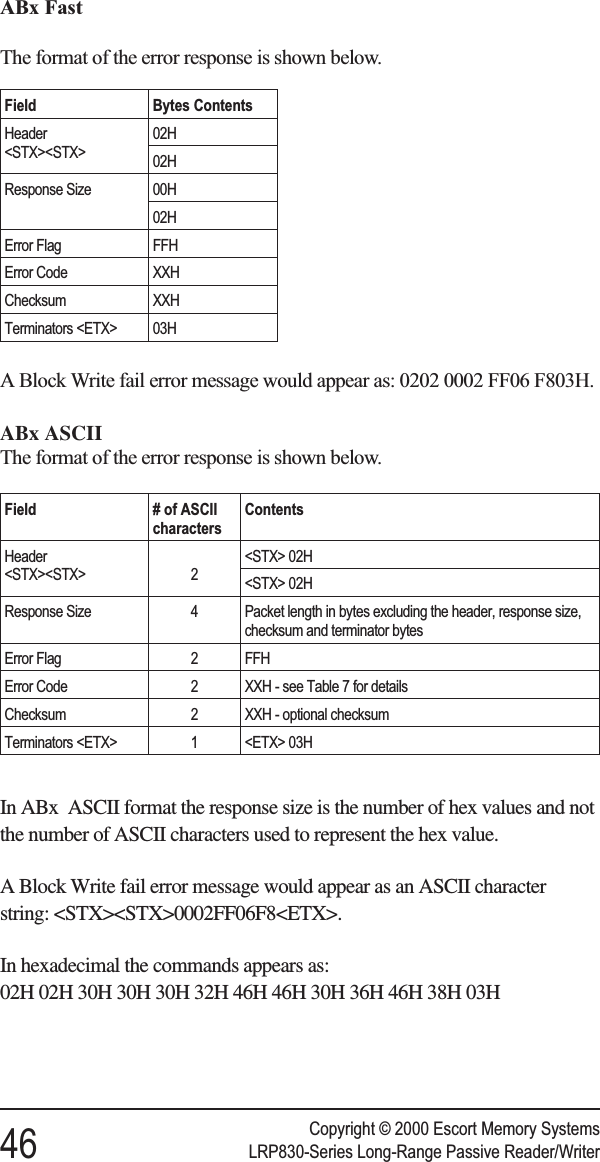
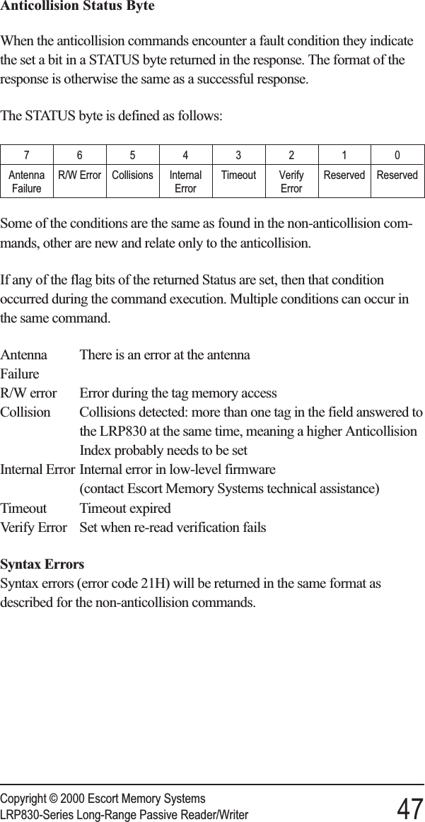
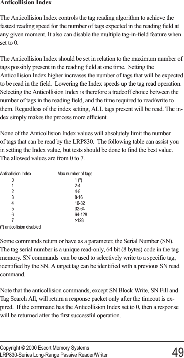
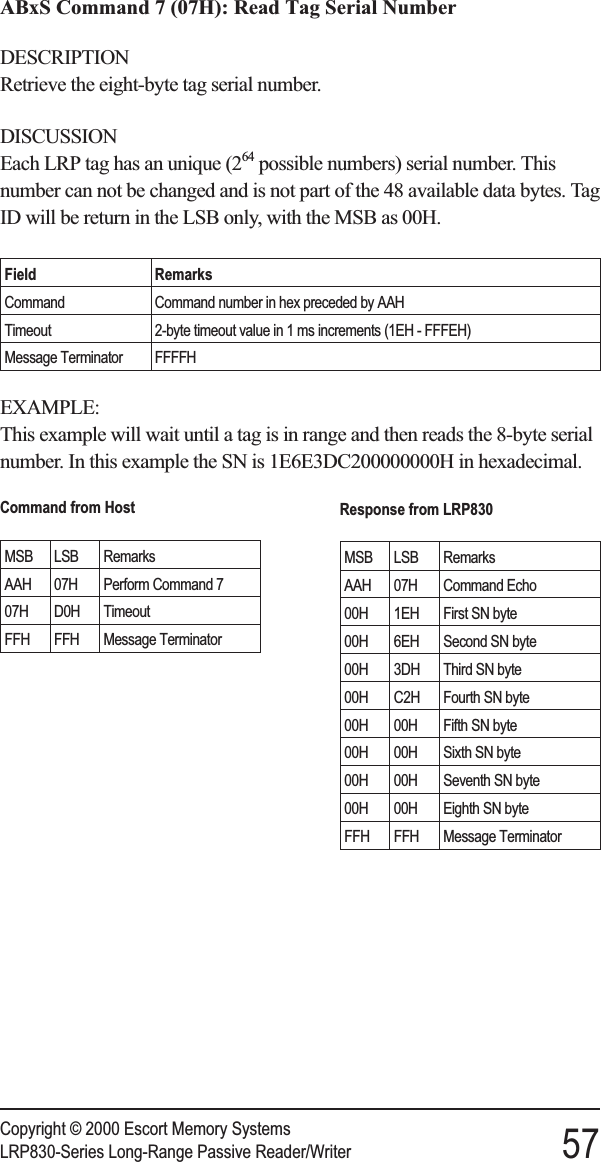
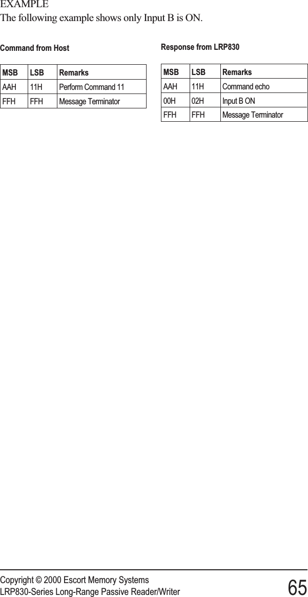
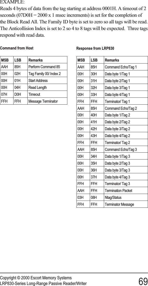
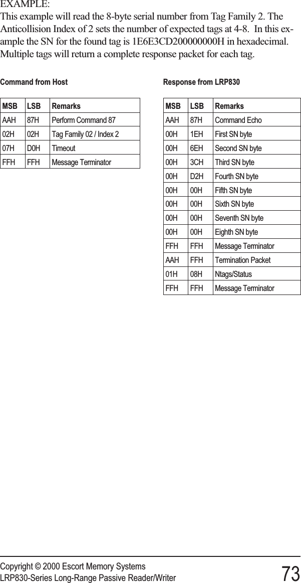
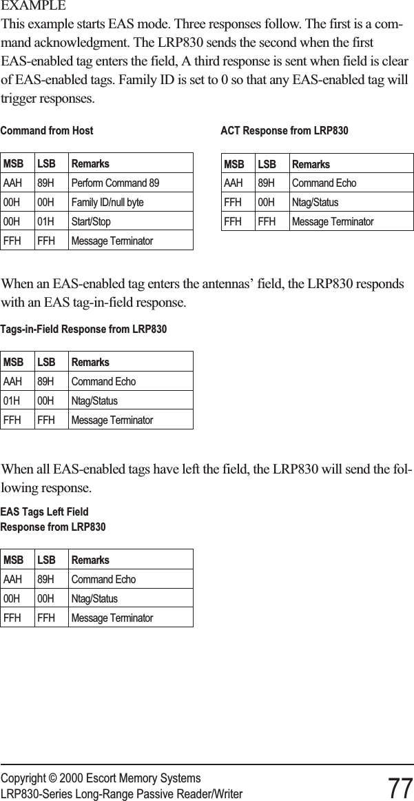
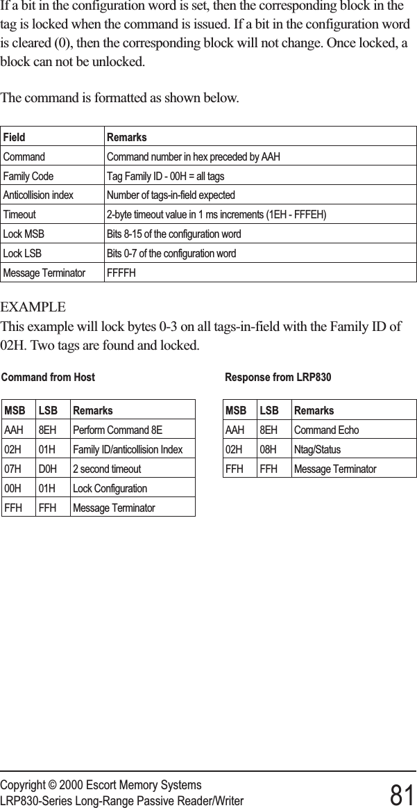
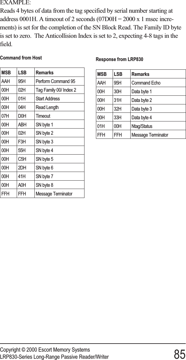
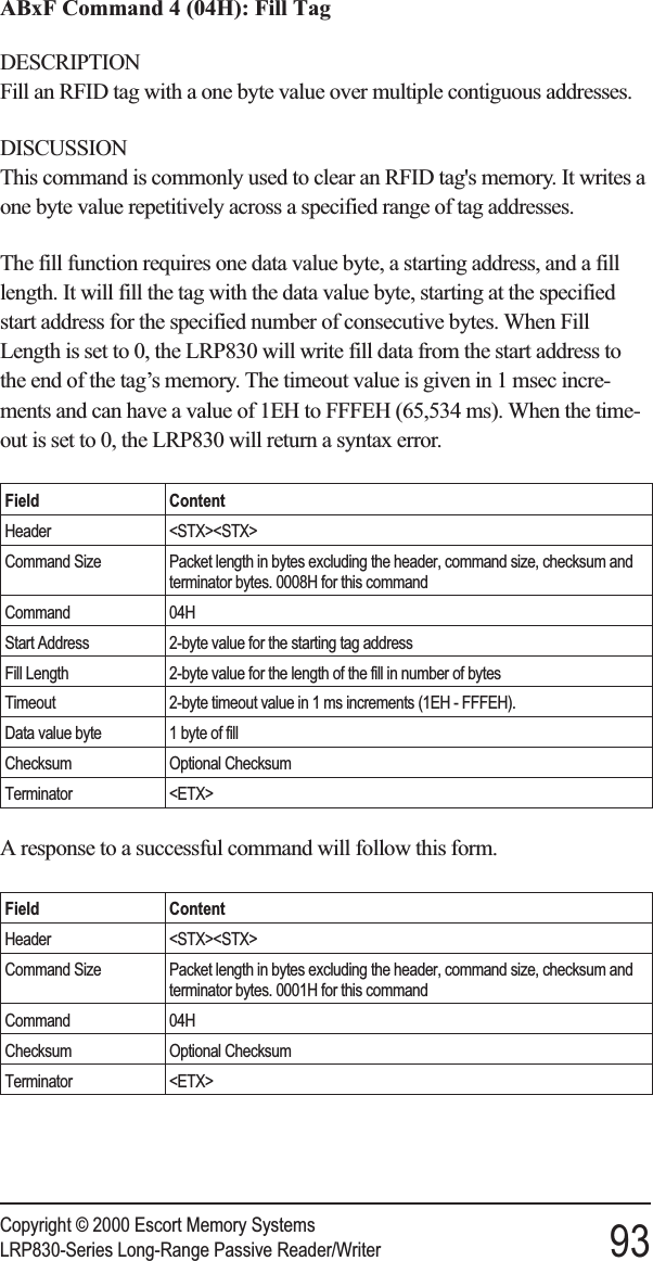
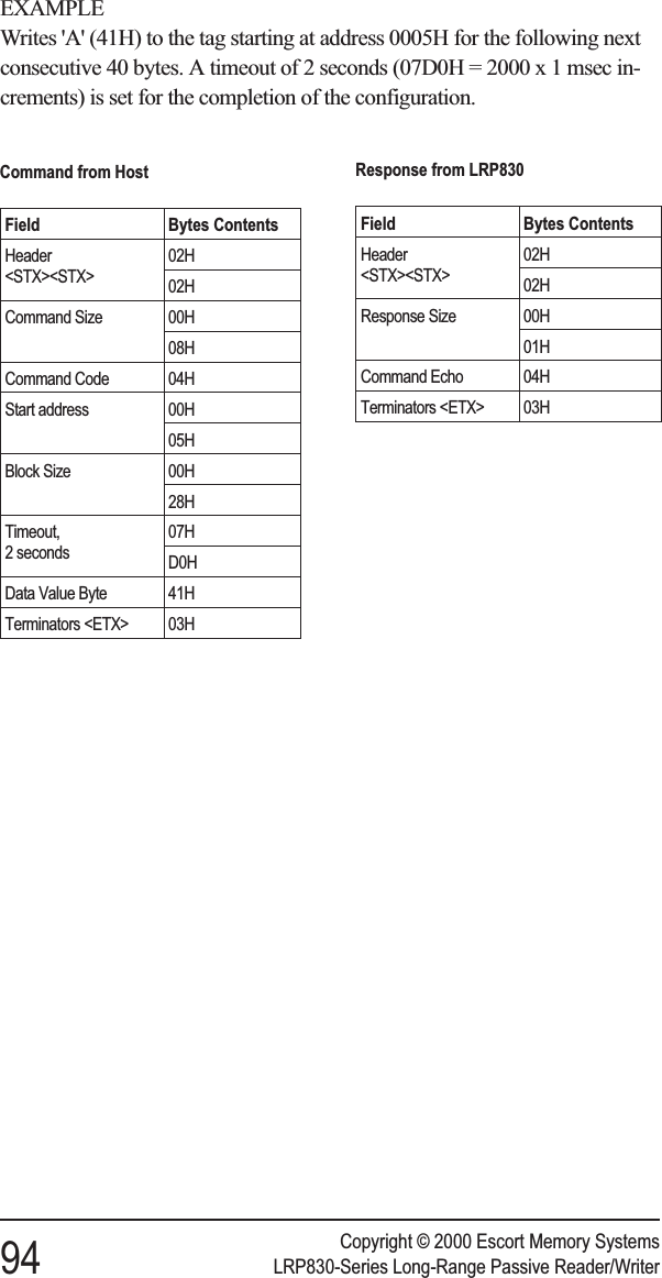
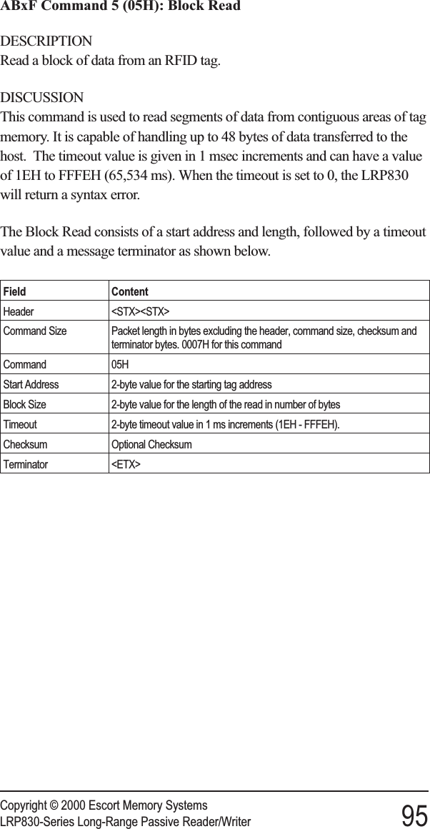
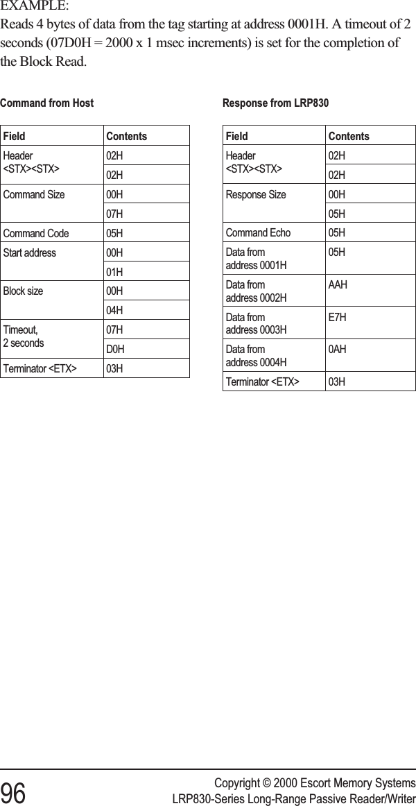
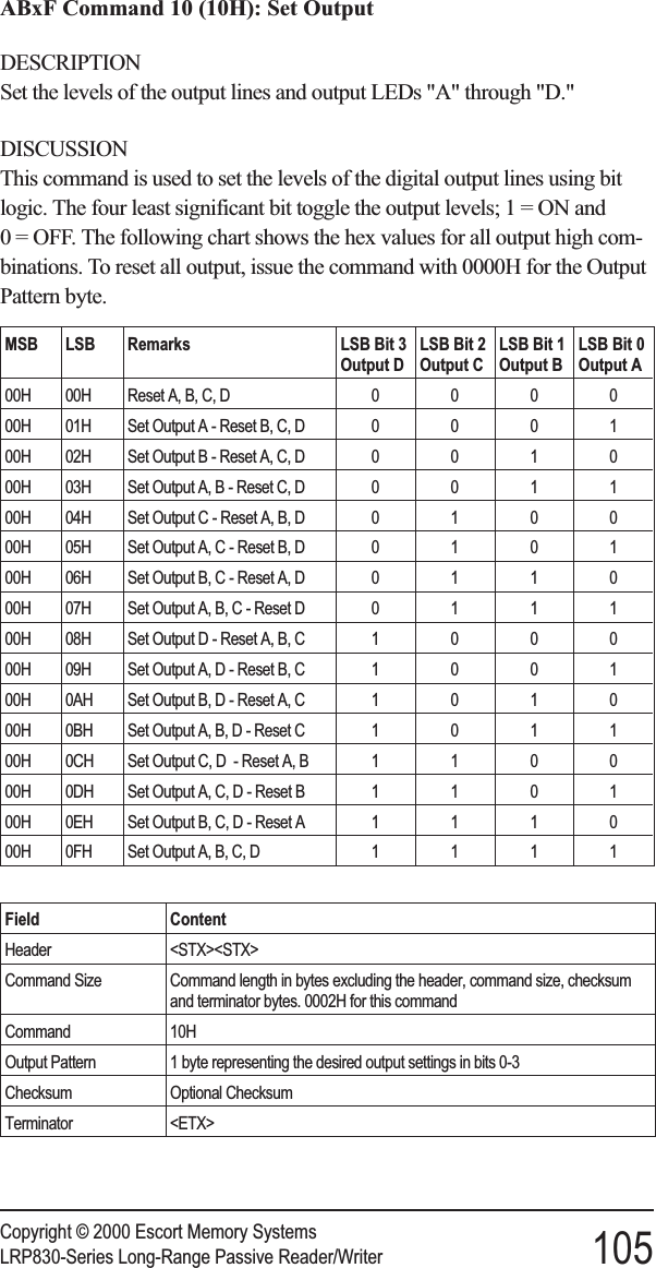
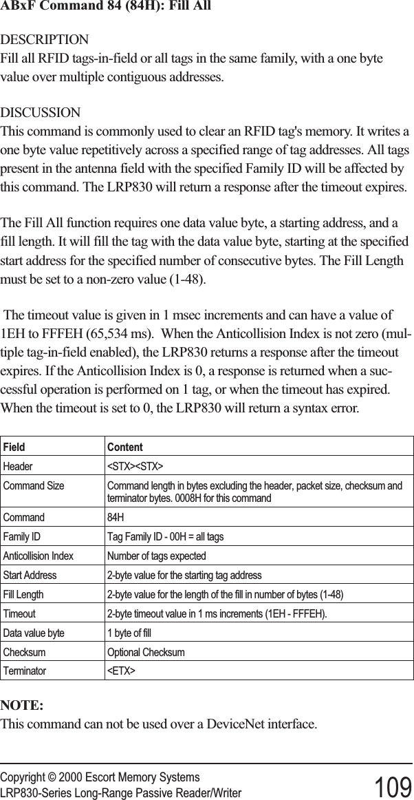
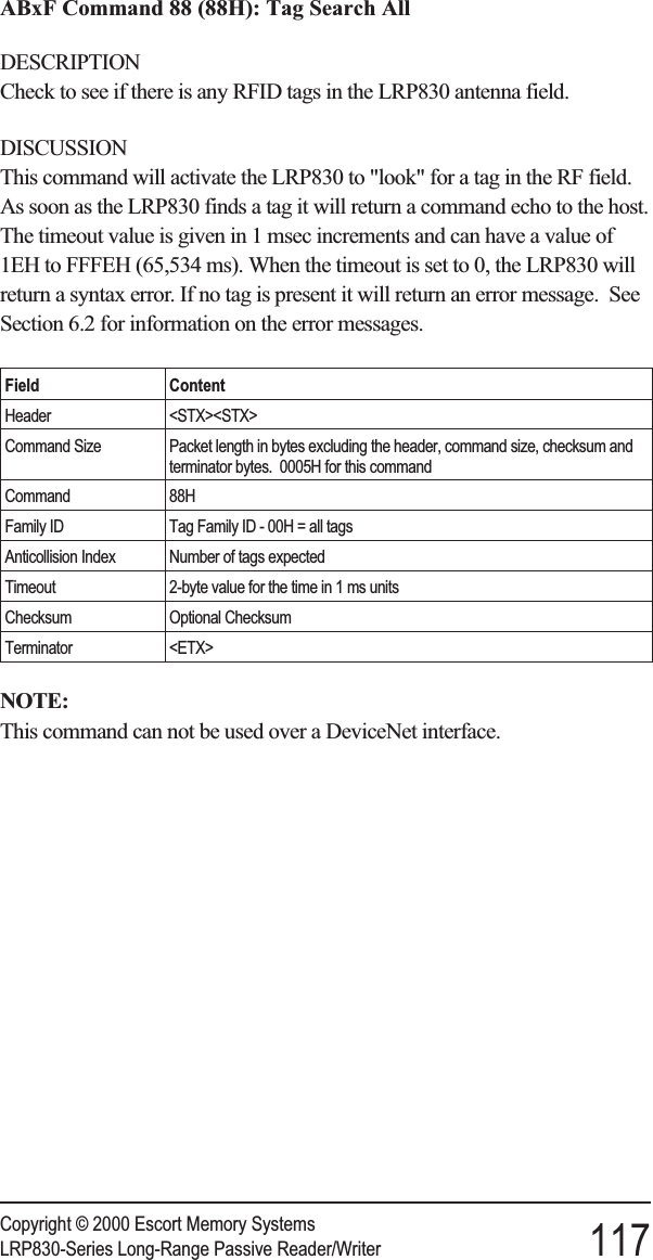
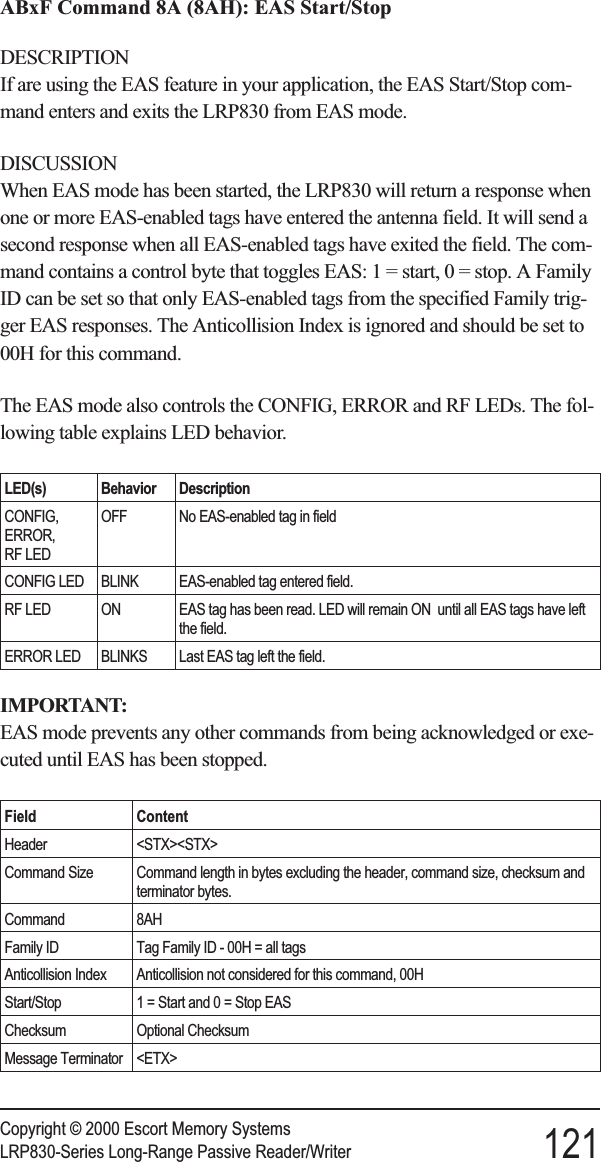
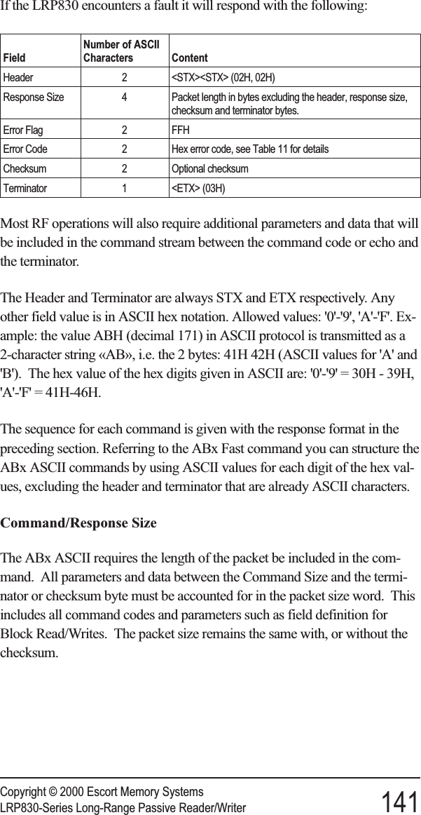
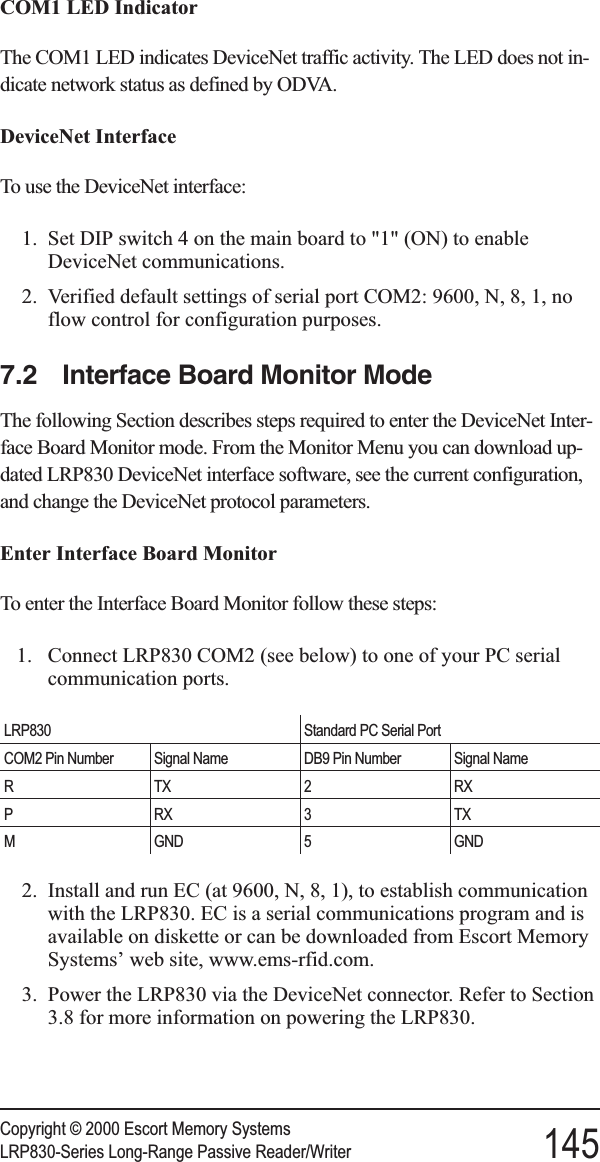
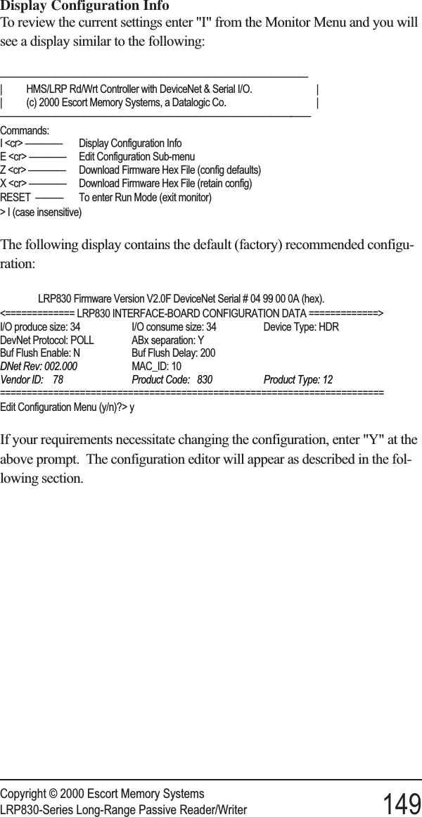
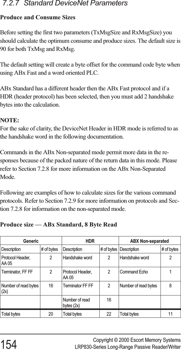
![To enter the Main Board configuration menu, cycle power or press the resetswitch, and then press CTRL-D within the first seven seconds of the initial-ization. The LRP830 will enter the Configuration Menu. As the LRP830starts the Configuration program, both the RF and CONFIG LEDs willflash. The Main Board Configuration menu will display with the currentsoftware version number together with the DSP firmware version.******************************************************LRP830 Standard ProgramSoftware V1.7C, June 2000DSP Firmware V1.7B, August 2000*******************************************************[1] Set-up Operating Parameters[2] Download New Program[3] Download DSP Firmware[4] Exit to Operating ModeEnter Selection:5.2 Set-up Operating ParametersTo change the operating parameters of the LRP830, enter 1 at the initialmenu. The following menu will be displayed, listing the current settings:The exact appearance of the menu display will depend on the settings youhave made, and will be updated when you save your changes.Serial Port COM1: RS232, 9600, N, 8, 1, No handshake (DIP switches)Serial Port COM2: RS232, 9600, N, 8, 1, No handshakeOperating Mode: ABx StandardRF Communication: Fast Mode[1] Set COM1 Parameters[2] Set COM2 Parameters[3] Set Operating Mode[4] Set RF Communications[5] Restore Factory Defaults[6] Return to Main MenuEnter Selection:Enter the number of the sub-menu you wish to enter. When you have madeyour selection you will be prompted to save your changes to the non-volatileEEPROM. For the new settings to take effect, you must save your changesto the EEPROM and reset the LRP830. If you do not save changes to theEEPROM, the new settings will be effective only until the LRP830 is reset.Copyright © 2000 Escort Memory Systems36 LRP830-Series Long-Range Passive Reader/Writer](https://usermanual.wiki/Balluff/LRP800.User-Manual-Lrp830/User-Guide-132570-Page-44.png)
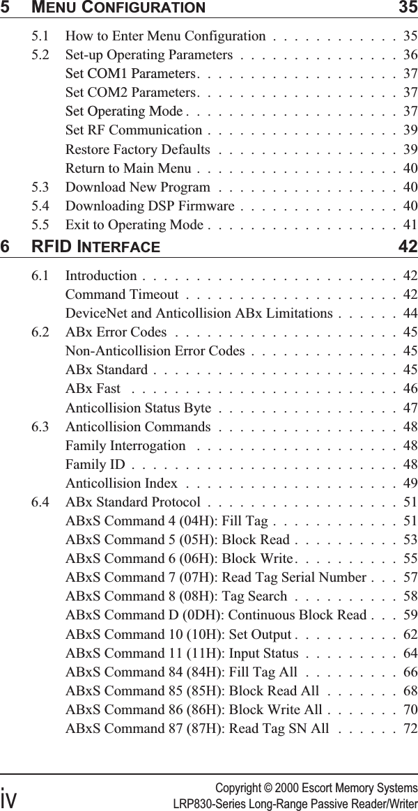
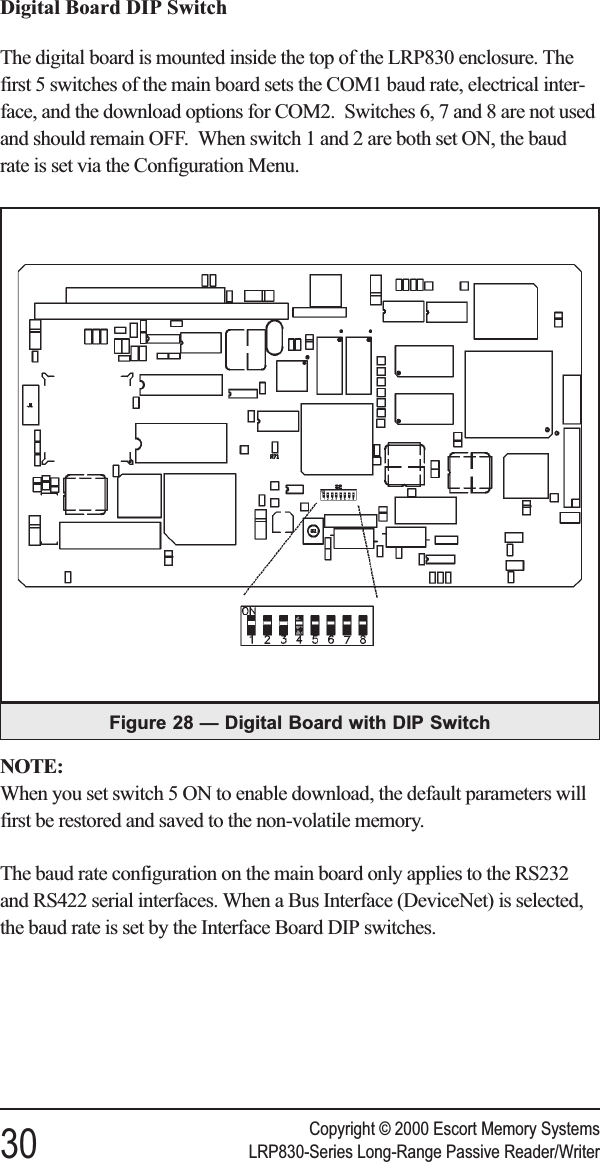
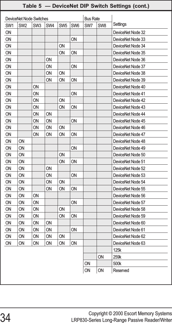
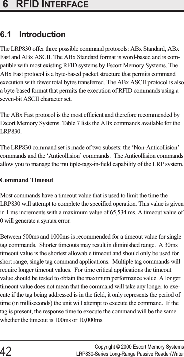
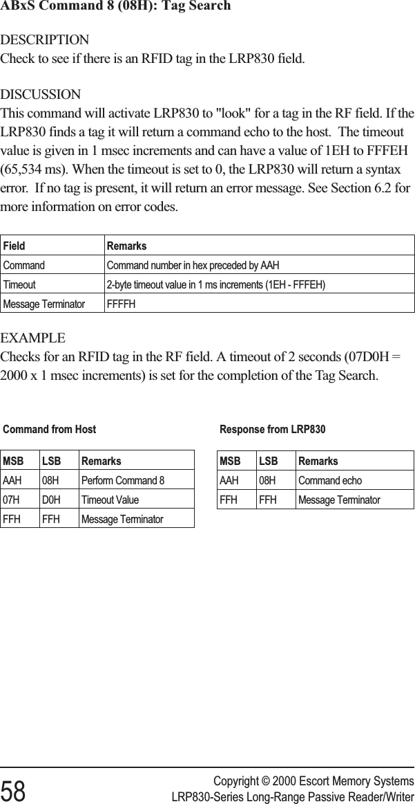
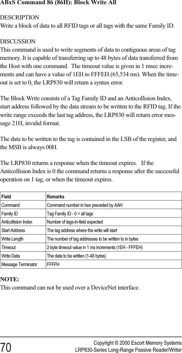
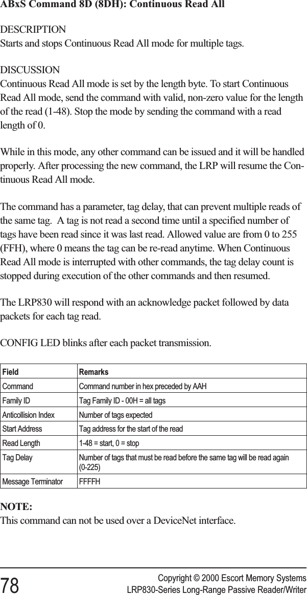
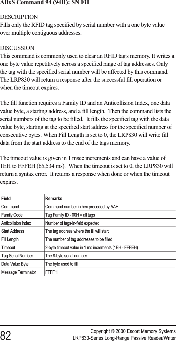
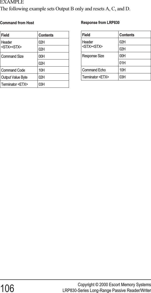
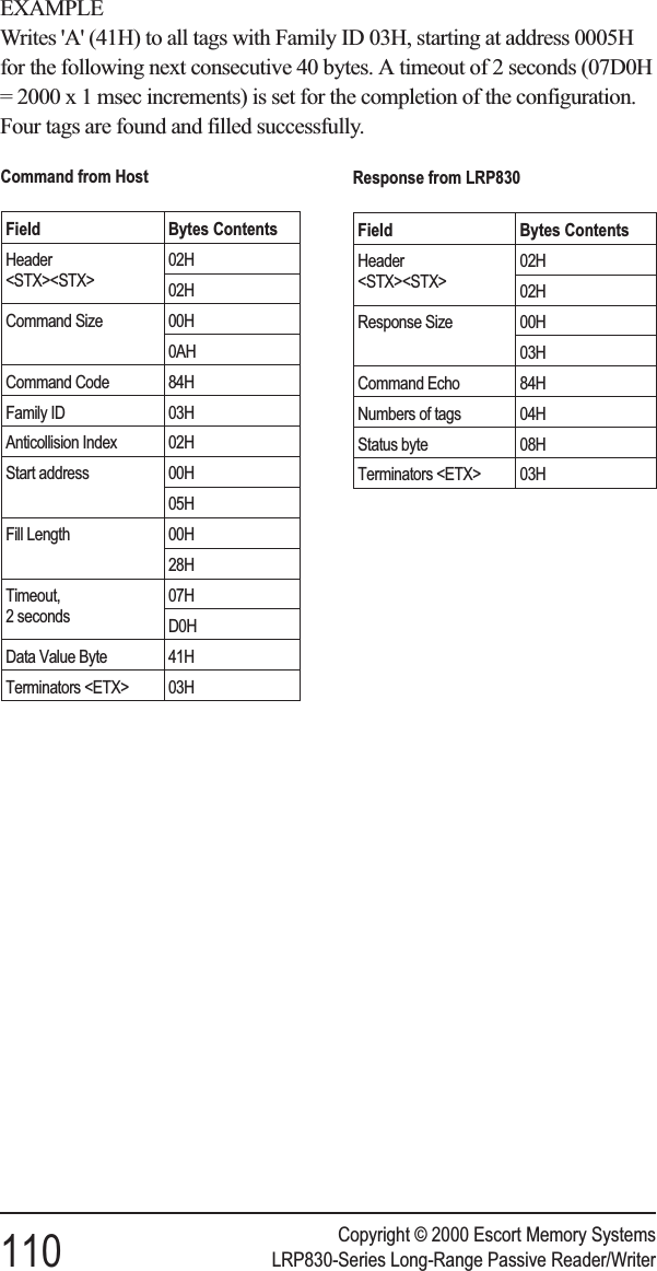
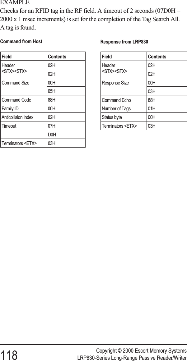
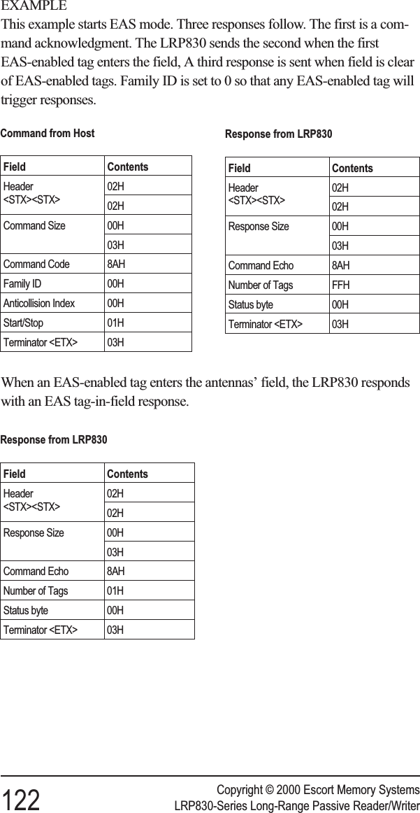
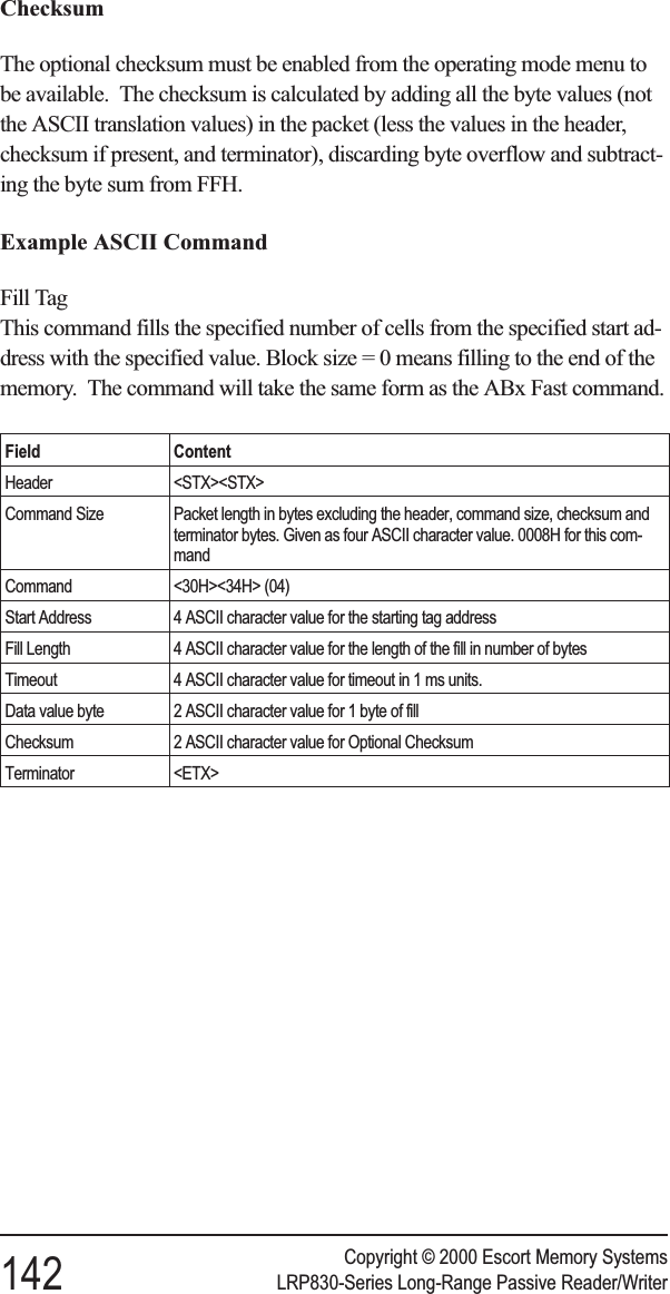
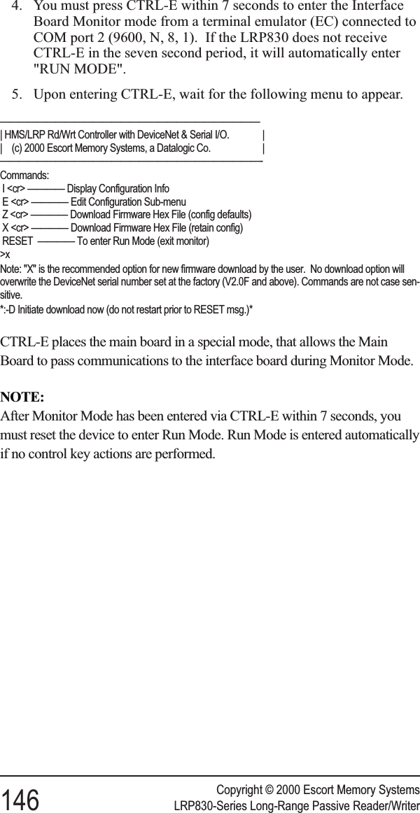
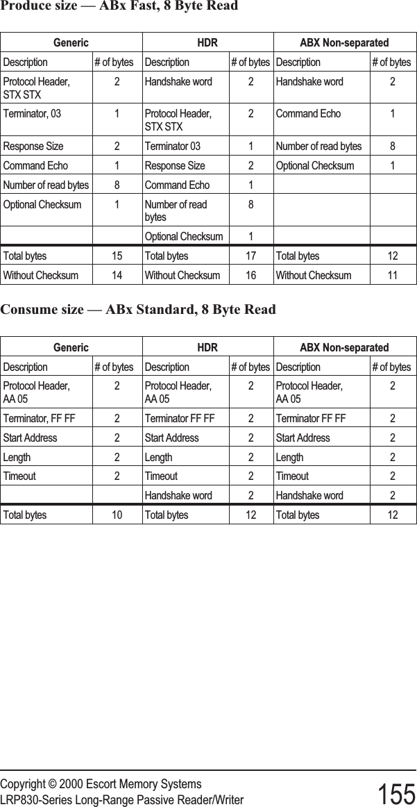
![The following sub-menus are presented here in their entirety. Actually themenus will presented one option at time, advancing as you enter selections.Some options shown are dependent on earlier selections.Set COM1 ParametersSelecting 1 from the above menu will present the following display for theCOM1 parameters. These settings are valid only if you are not using theDeviceNet Interfaces (e.g. DIP switch 4 is in the OFF position). Enter theappropriate number at each prompt. The default values are indicated by anasterisk (*).*** Set COM1 Parameters ***Baud Rate? [0] 1200 [1] 2400 [2] 4800 [3] 9600* [4] 19200 [5] 38400Data size? [0] 7 bit [1] 8 bit*Parity? [0] None* [1] Even [2] OddHandshake? [0] None* [1] Xon/XoffSave Changes to EEPROM? [0] No [1] YesSet COM2 ParametersSelecting 2 from the above menu will bring to the following display for theCOM2 parameters. Enter the appropriate number at each prompt. Thedefault values are indicated by an asterisk.*** Set COM2 Parameters ***Baud Rate? [0] 1200 [1] 2400 [2] 4800 [3] 9600* [4] 19200Data size? [0] 7 bit [1] 8 bit*Parity? [0] None* [1] Even [2] OddHandshake? [0] None* [1] Xon/XoffSave Changes to EEPROM? [0] No [1] YesSet Operating ModeThe Set Operating Mode menu allows you to choose the command protocolthe LRP830 will use or configure it to automatically enter Continuous ReadMode upon start-up.Copyright © 2000 Escort Memory SystemsLRP830-Series Long-Range Passive Reader/Writer 37](https://usermanual.wiki/Balluff/LRP800.User-Manual-Lrp830/User-Guide-132570-Page-45.png)
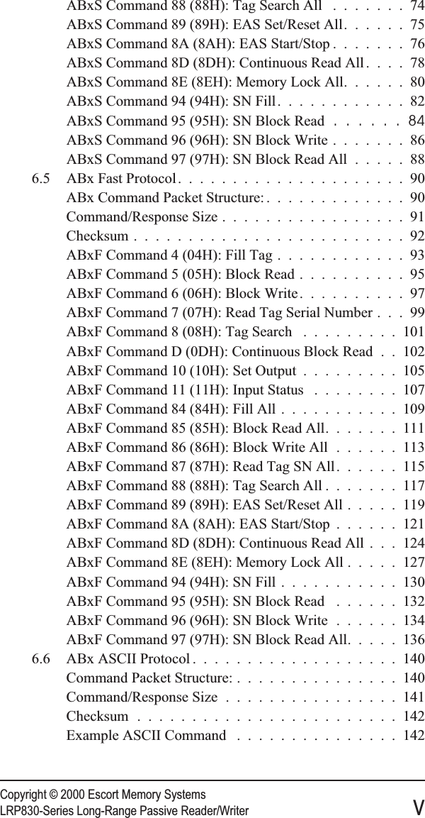
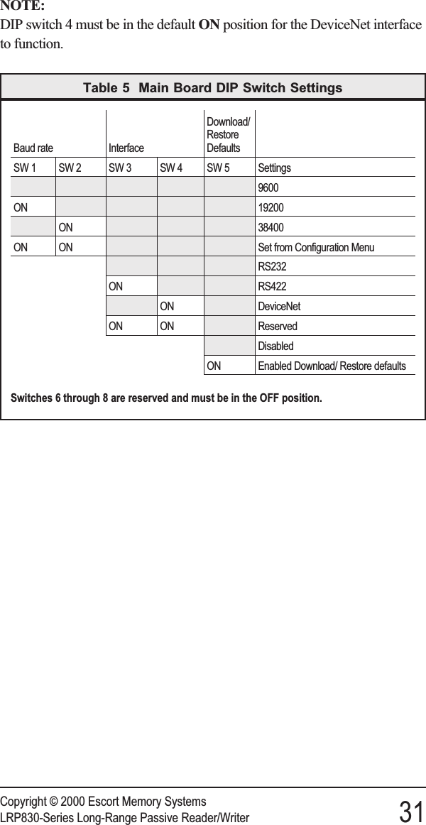
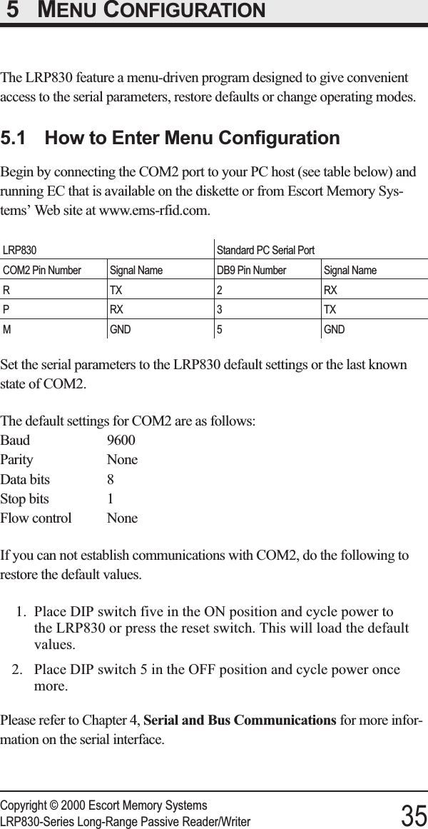
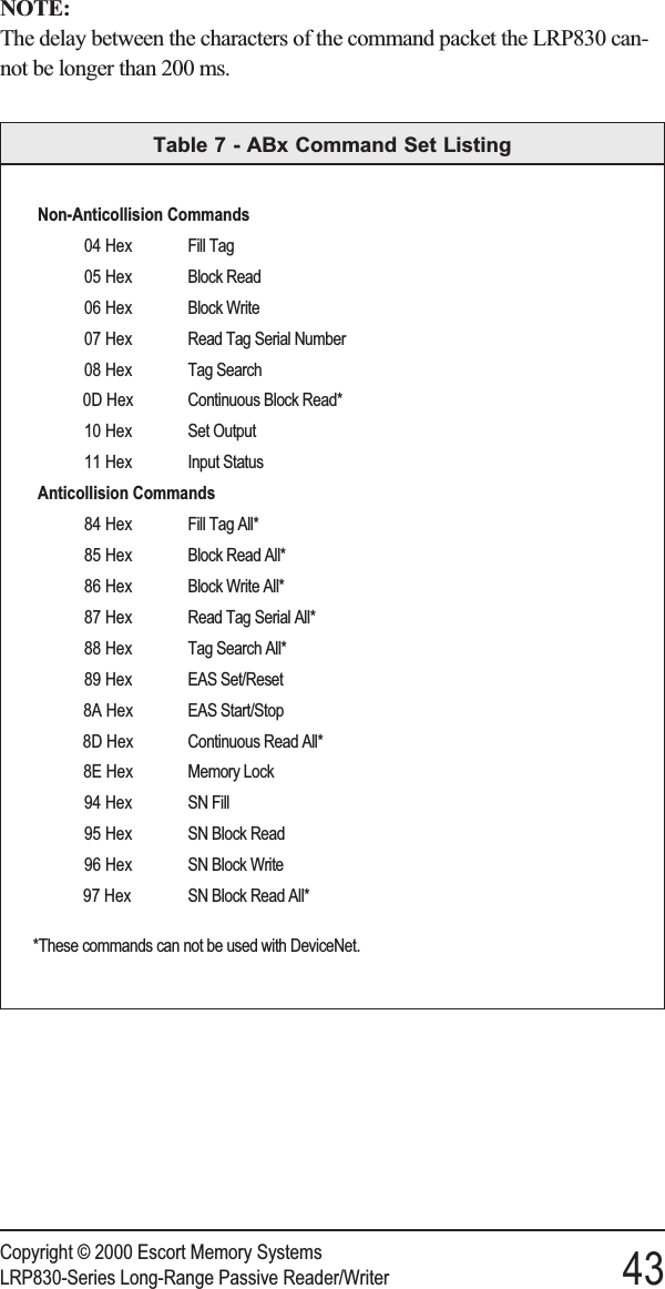
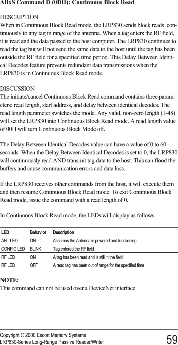
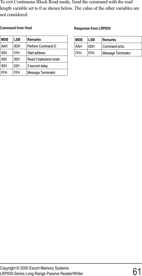
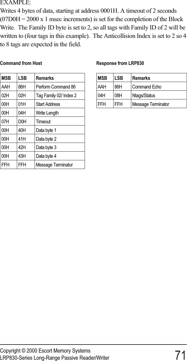
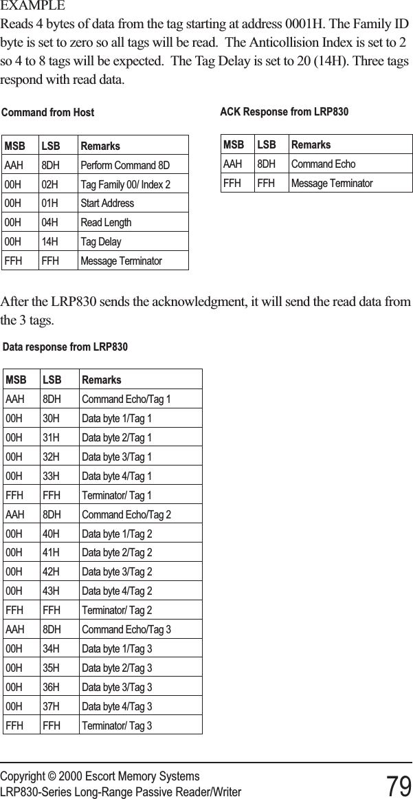
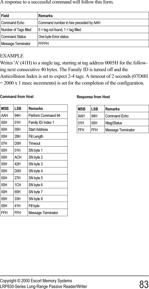
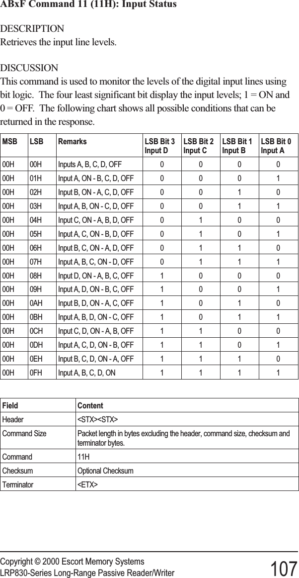
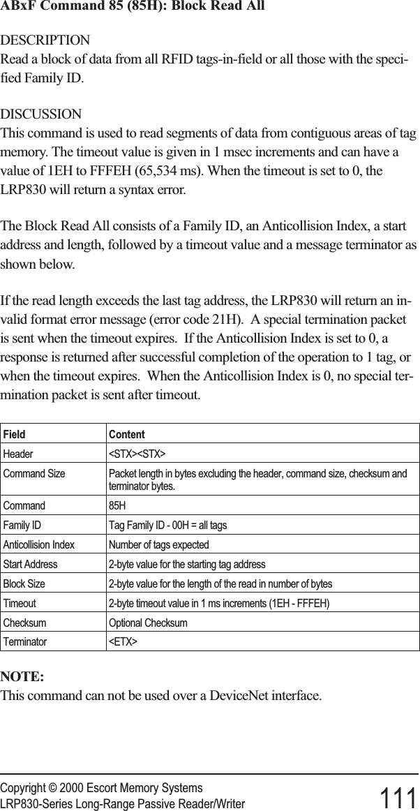
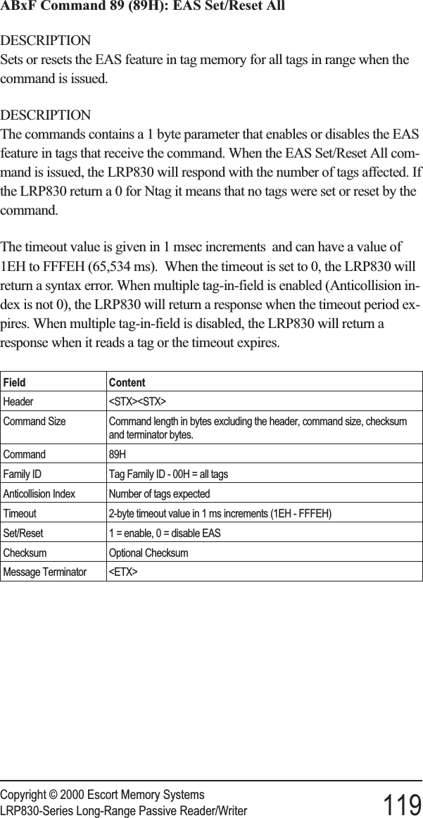
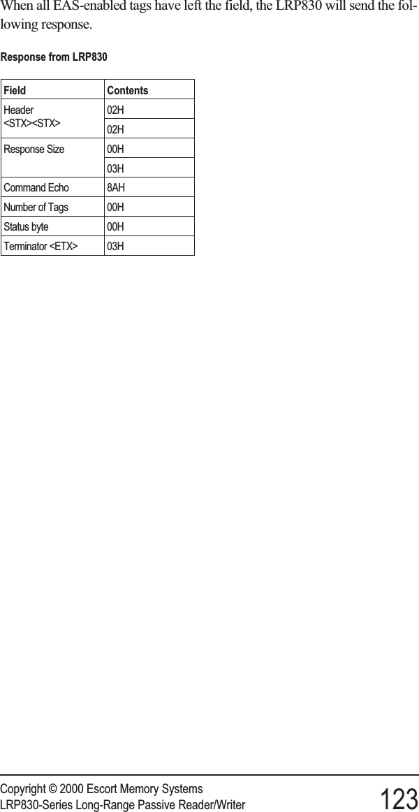
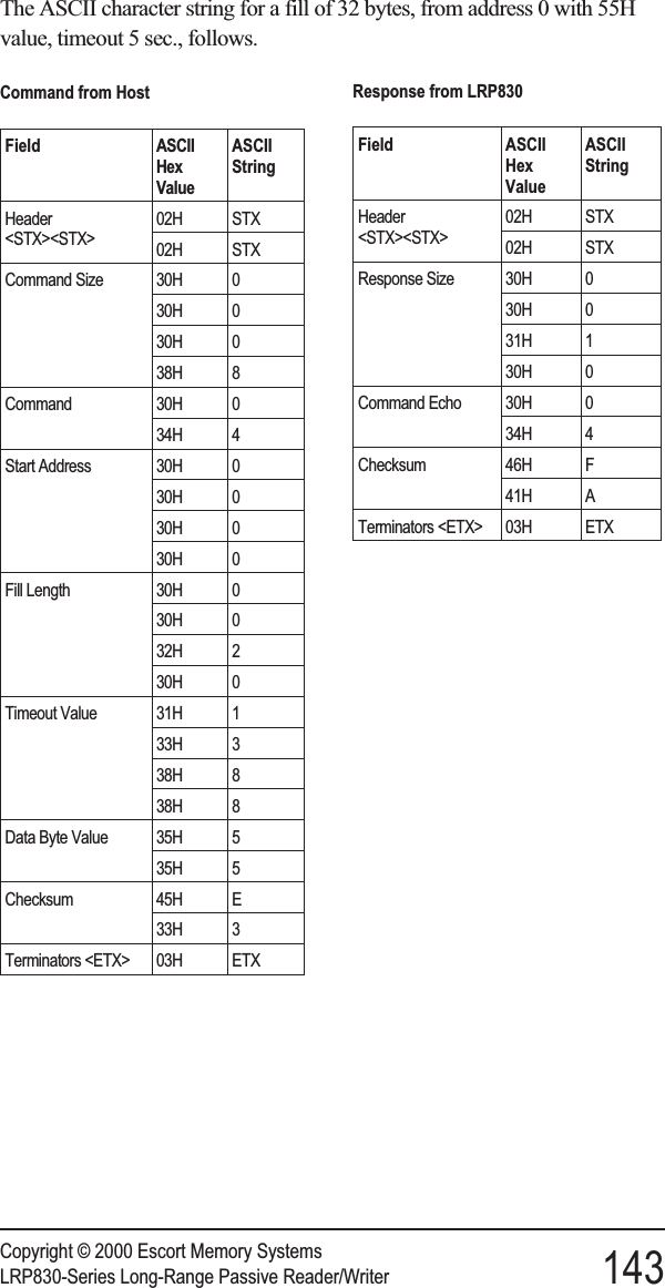
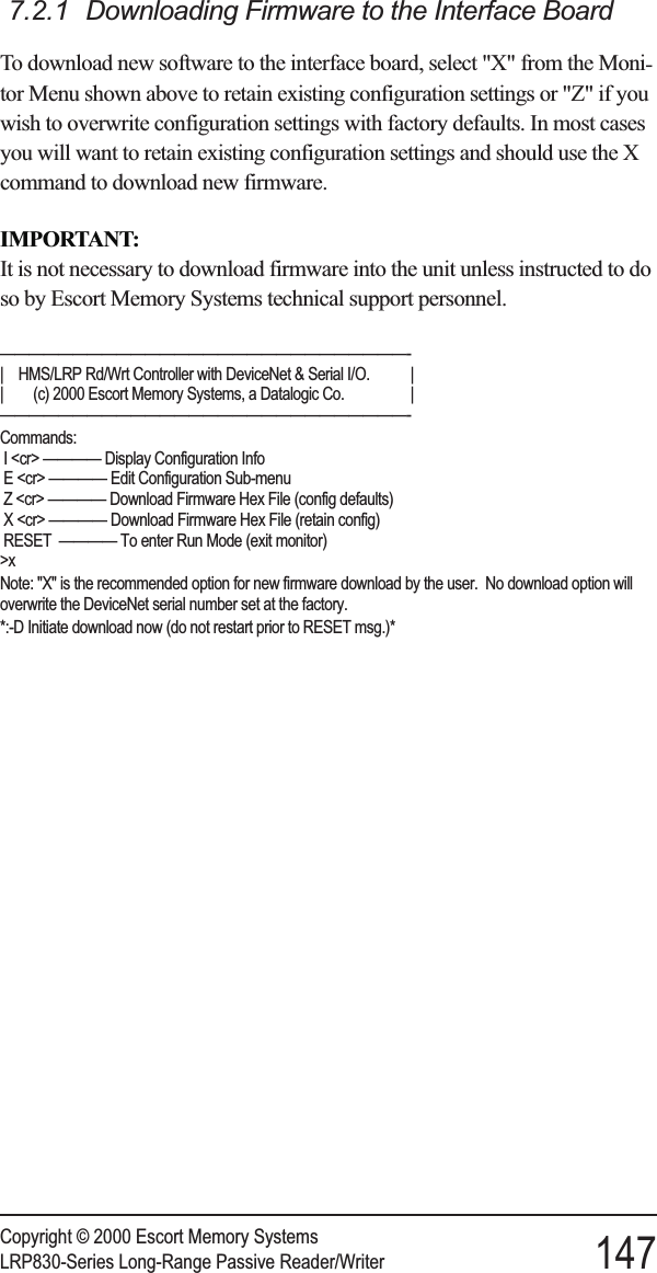
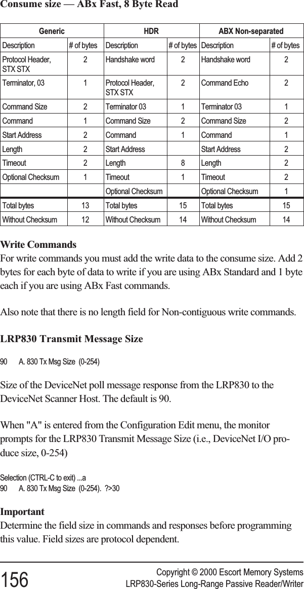
![*** Set Operating Mode ***Command Protocol? [0] ABx Standard* [1] ABx Fast [2] ABx ASCIIChecksum? [0] Disabled* [1] EnabledPower up in Continuous Read Mode? [0] NO [1] Single Tag [2] Multiple TagStart Address (0 to 47)Length (1 to 48)Delay Between Duplicate Decodes (0 to 60)Raw Read Response? [0] NO [1] CR terminate [2] CR/LF terminateSave Changes to EEPROM? [0] No [1] YesCommand Protocol?The LRP830 offers three modes for the transfer of data and commands. ABxStandard (ABxS) uses only the LSB for tag data while ABx Fast (ABxF)will use both the MSB and the LSB for the passing of data. ABx ASCII(ABxA) mode permits RFID operations using seven bit data packets in theform of printable ASCII characters.Checksum?ABx Fast and ABx ASCII also permits you to include a checksum in thecommand. To use a checksum value with the ABx commands, you mustenable the checksum option. It is recommended that you enable thechecksum option.Power up in Continuous Read Mode?You also have the option of setting the LRP830 to start-up in ContinuousRead Mode. When you have configured the LRP830 to function in thismanner, you do not issue commands to the LRP830. It will, upon start-up,enter directly into a Continuous Read Mode. Since this bypasses the normalcommand parameters, you must specify the Continuous Read Modeparameters.The LRP830 will respond to other commands and resume Continuous ReadMode when completed.This option will not function over a DeviceNet bus.If you are using your LRP830 in this mode, you must choose if you want theLRP830 to read a single tag or read multiple tags within the field.To exit Continuous Read Mode you must either re-enter the configurationmenu and select NO from the Power up in Continuous Read Mode option,or issue a Continuous Read command from the host with a read length of 0as described in Chapter 6, RFID Interface.Copyright © 2000 Escort Memory Systems38 LRP830-Series Long-Range Passive Reader/Writer](https://usermanual.wiki/Balluff/LRP800.User-Manual-Lrp830/User-Guide-132570-Page-46.png)
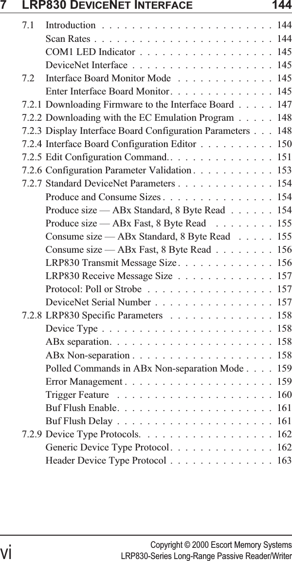
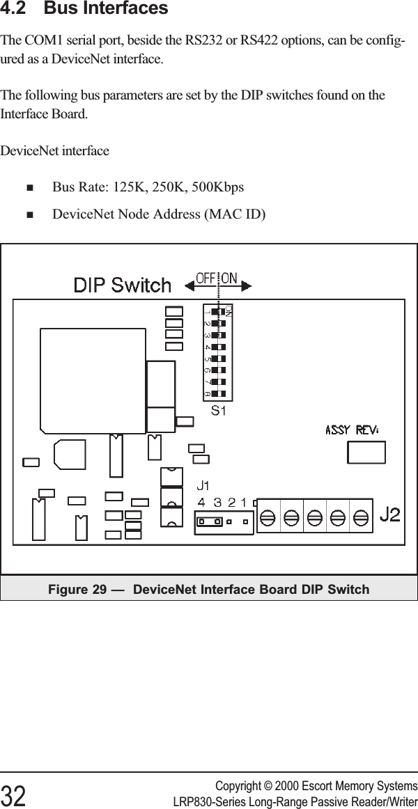
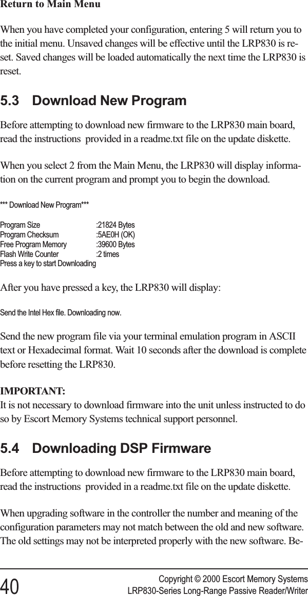
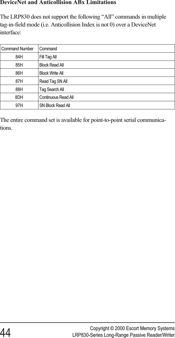
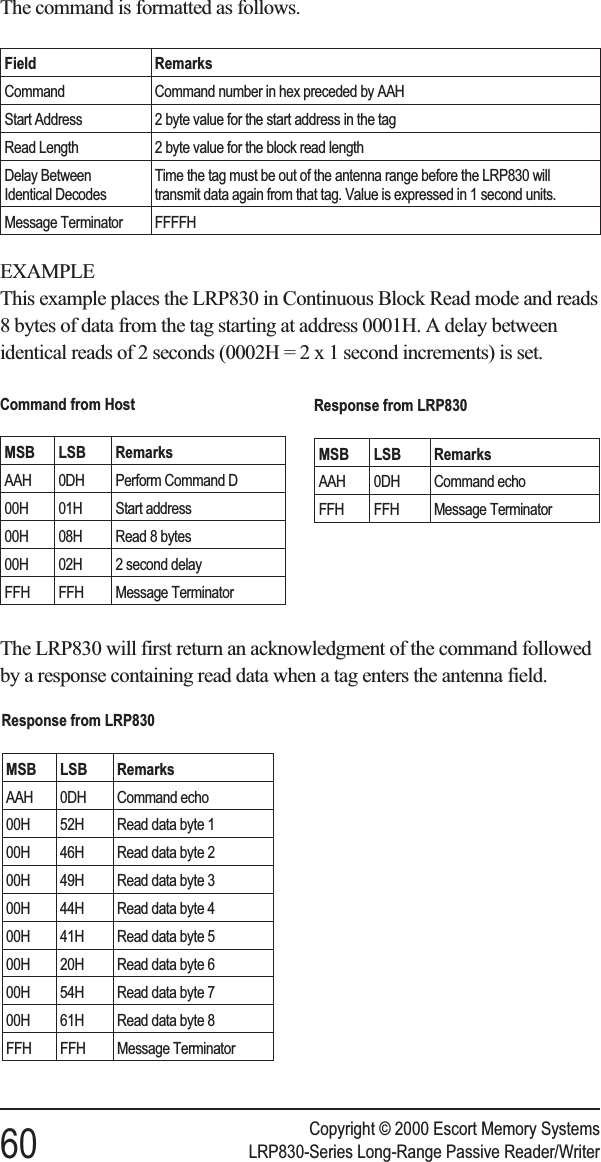
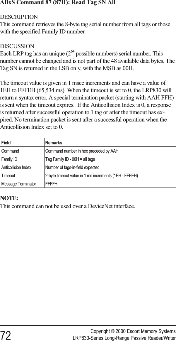
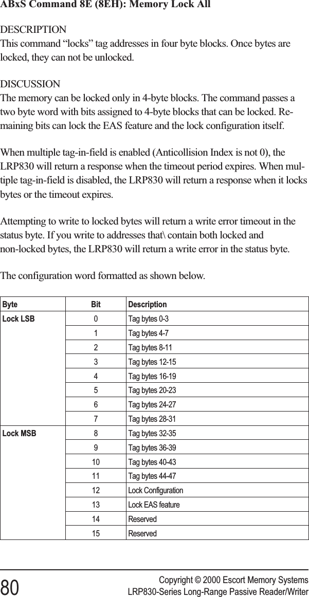
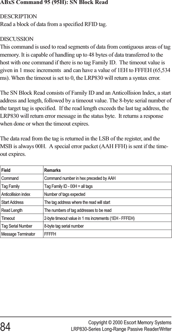
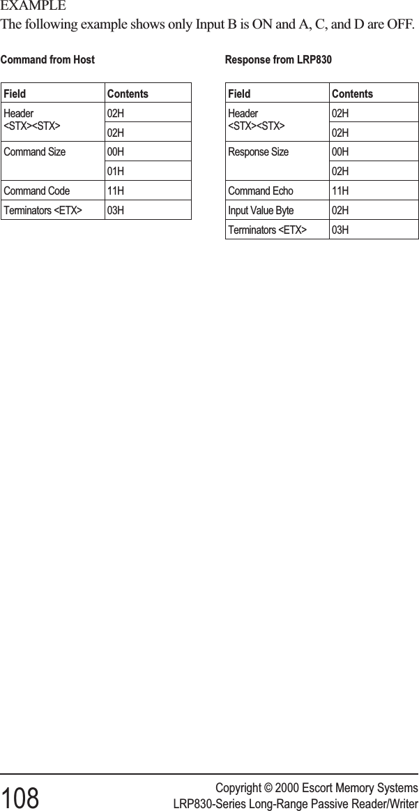
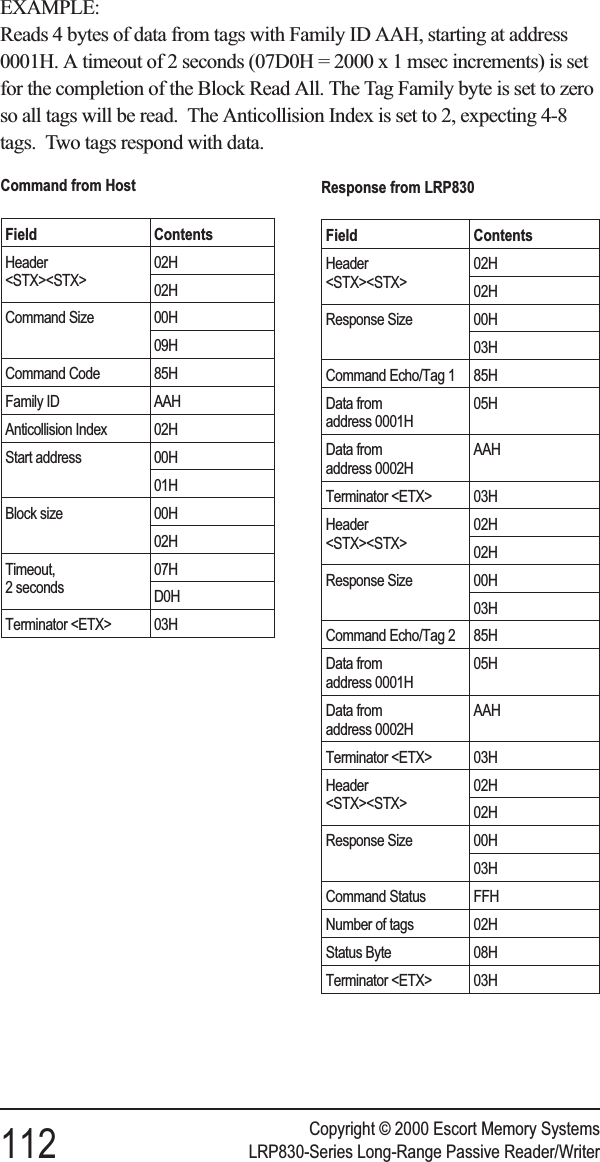
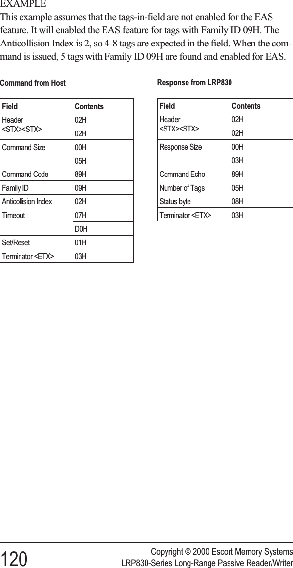
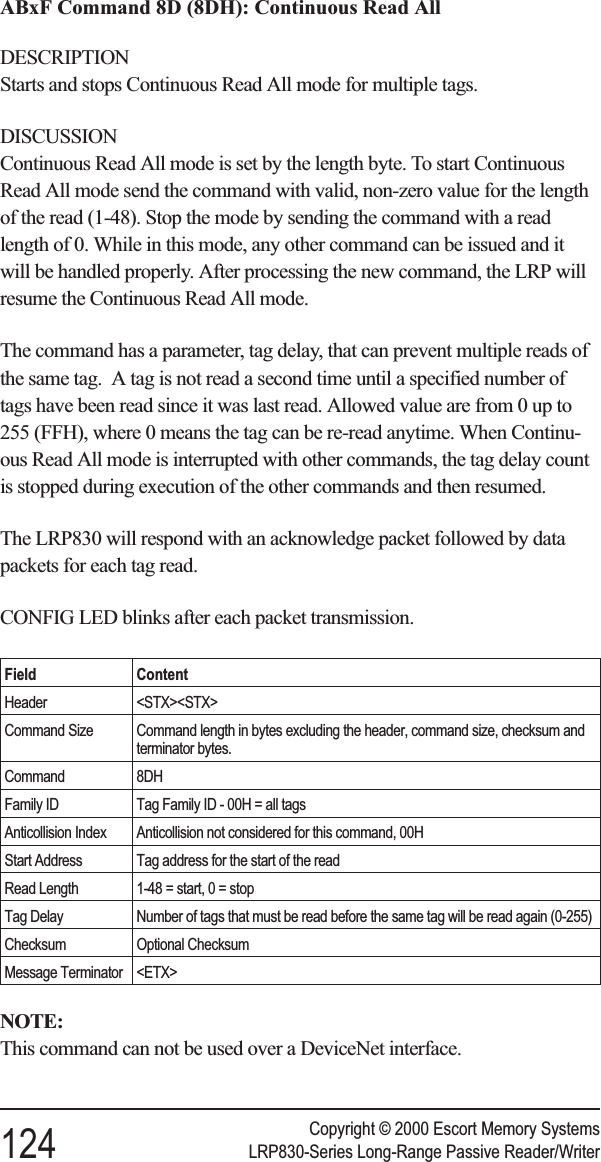
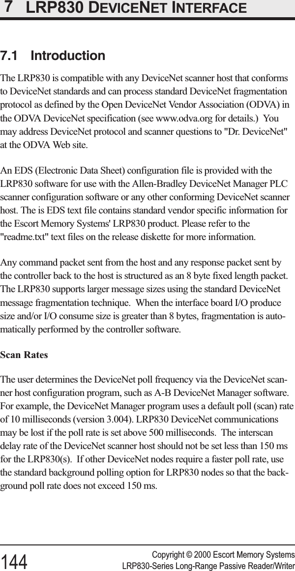
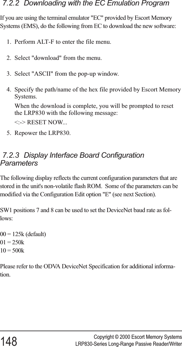
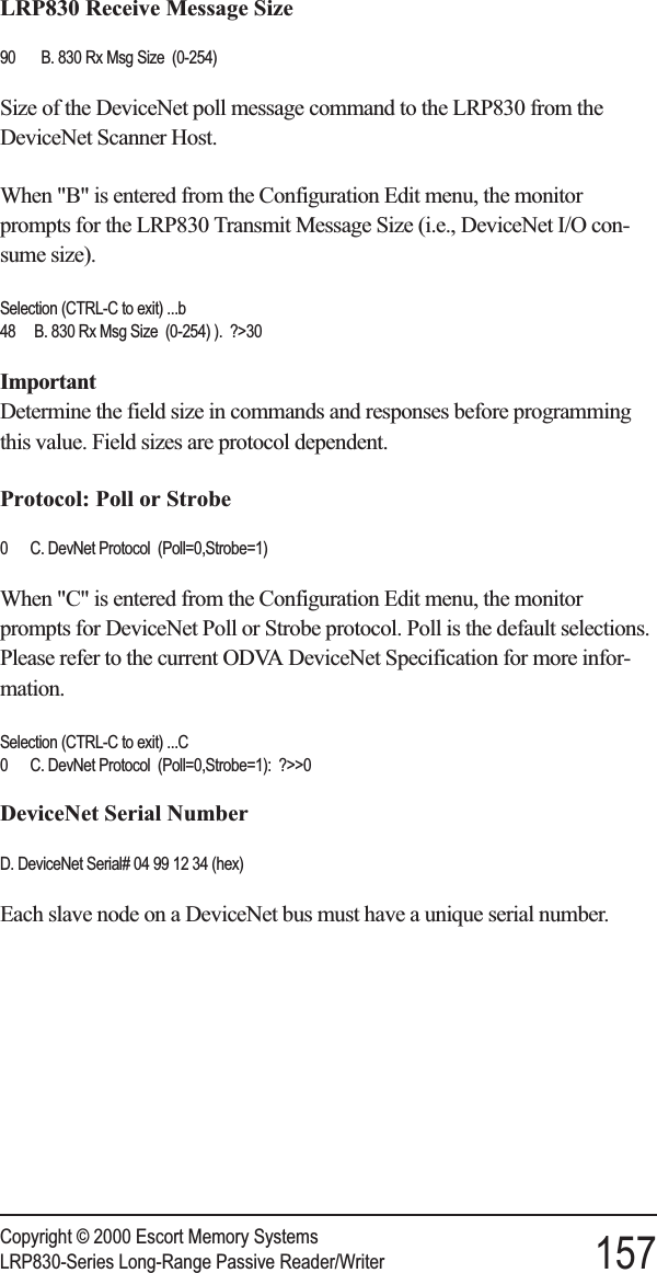
![Start Address (0-47)Enter the tag address where you want the read to begin.Length (1-48)Enter the length of the read you wish the LRP830 to perform. Make certainthat the length value does not exceed the number of possible addresses fol-lowing the starting tag address. Entering a read length of 0 will disable Con-tinuous Read Mode.Delay Between Identical Decodes (0-60)The Delay Between Identical Decodes parameters can have a value of 0 to60 seconds. When the Delay Between Identical Decodes is set to 0, theLRP830 will continuously read AND transmit tag data to the host. This canflood the buffers and cause communication errors and data loss.Raw Read Response?If you have selected ABx Fast or ABx ASCII, you have the option of strip-ping the command protocol from the data and adding a terminator to sepa-rate the data packets. You can choose a CR (0DH) or CR/LF (0DH, 0AH) toterminate the data.Set RF CommunicationThe LRP830 should be configured with the default (0) Fast Mode.*** Set RF Communication ***RF Communication? [0] Fast Mode* [1] Standard Mode 0Save Changes to EEPROM? [0] No [1] YesRestore Factory DefaultsIt is often helpful during troubleshooting to restore the LRP830 to knowndefault values. To do so, select 1from this menu.*** Restore Factory Defaults ***Restore Factory Default? [0] No [1] YesThe restored defaults will be saved to the EEPROM. The communicationdefaults can also be restored by placing the main board DIP switch number 5in the ON position and then restarting the LRP830. After you have savedany changes, you must re-initialize the LRP830 with switch 5 in the OFFposition.Copyright © 2000 Escort Memory SystemsLRP830-Series Long-Range Passive Reader/Writer 39](https://usermanual.wiki/Balluff/LRP800.User-Manual-Lrp830/User-Guide-132570-Page-47.png)
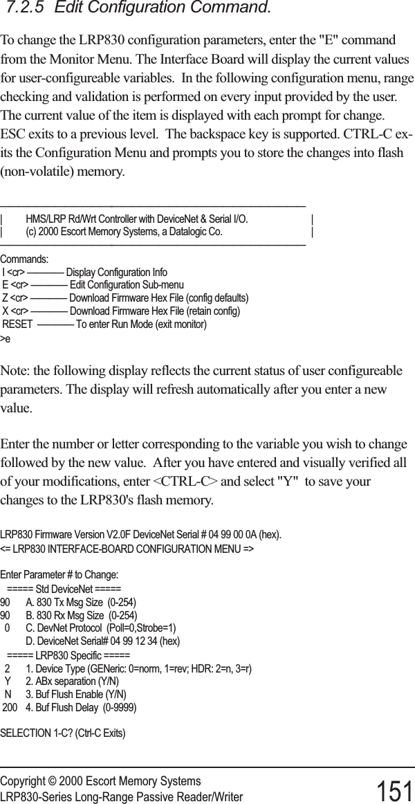
![7.2.4 Interface Board Configuration EditorNote: the following menu can be attained via "Y" (above) or selecting "E"from the Monitor Menu (above). These are the recommended parameters,however, it is likely that A and/or B (below) may require modification ac-cording to customer requirements.<= LRP830 INTERFACE-BOARD CONFIGURATION MENU =>Enter Parameter # to Change:===== Std DeviceNet =====90 A. 830 Tx Msg Size (0-254)90 B. 830 Rx Msg Size (0-254)0 C. DevNet Protocol (Poll=0,Strobe=1)D. DeviceNet Serial# 04 99 12 34 (hex)===== LRP830 Specific =====2 1. Device Type (GENeric: 0=norm, 1=rev; HDR: 2=n, 3=r)Y 2. ABx separation (Y/N)N 3. Buf Flush Enable (Y/N)200 4. Buf Flush Delay (0-9999)SELECTION 1-C? (Ctrl-C Exits)When you wish to exit the interface board configuration menu, enter"CTRL-C." The following prompt will appear which is responded with "n"in this example.Update Flash ROM (y/n)?> n [:-( Flash ROM *Not* Updated )-:]{-:) Please Reset LRP830 to enter RUN mode (:-}{HALTED}<RESET>The LRP830 must now be reset or power cycled to enable the unit to enter"RUN" mode.Copyright © 2000 Escort Memory Systems150 LRP830-Series Long-Range Passive Reader/Writer](https://usermanual.wiki/Balluff/LRP800.User-Manual-Lrp830/User-Guide-132570-Page-158.png)
![Copyright © 2000 Escort Memory SystemsLRP830-Series Long-Range Passive Reader/Writer 169Decimal Hex Character064 40 @065 41 A066 42 B067 43 C068 44 D069 45 E070 46 F071 47 G072 48 H073 49 I074 4A J075 4B K076 4C L077 4D M078 4E N079 4F O080 50 P081 51 Q082 52 R083 53 S084 54 T085 55 U086 56 V087 57 W088 58 X089 59 Y090 5A Z091 5B [092 5C \093 5D ]094 5E ^^095 5F —Decimal Hex Character096 60 `097 61 a098 62 b099 63 c100 64 d101 65 e102 66 f103 67 g104 68 h105 69 i106 6A j107 6B k108 6C l109 6D m110 6E n111 6F o112 70 p113 71 q114 72 r115 73 s116 74 t117 75 u118 76 v119 77 w120 78 x121 79 y122 7A z123 7B {124 7C |125 7D }126 7E ~127 7F DEL](https://usermanual.wiki/Balluff/LRP800.User-Manual-Lrp830/User-Guide-132570-Page-177.png)
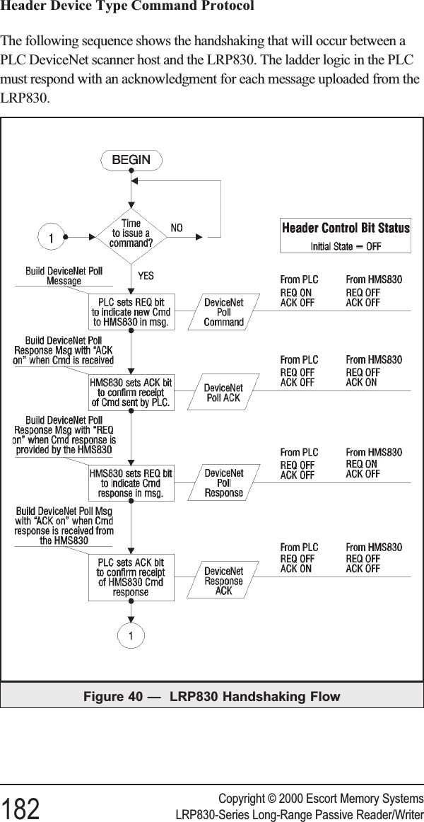
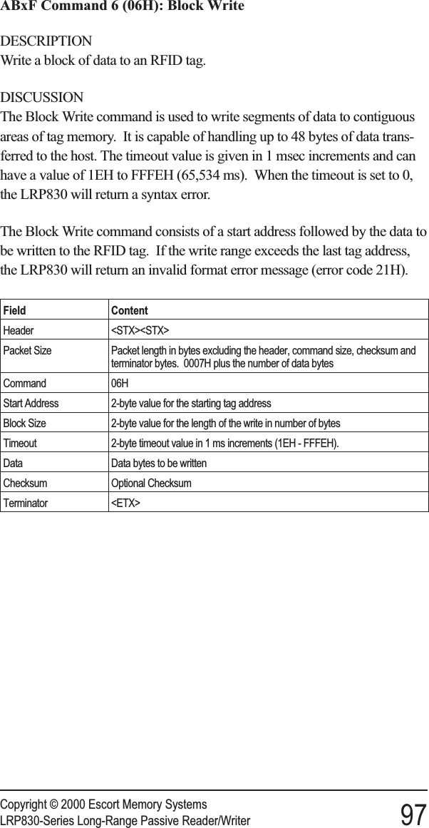
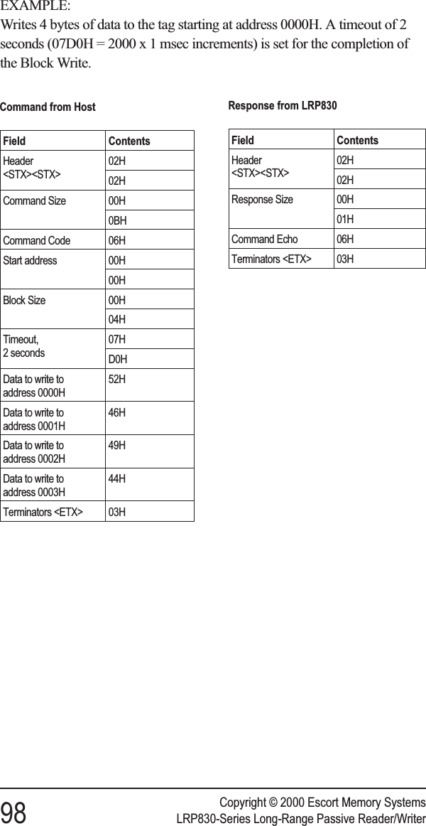
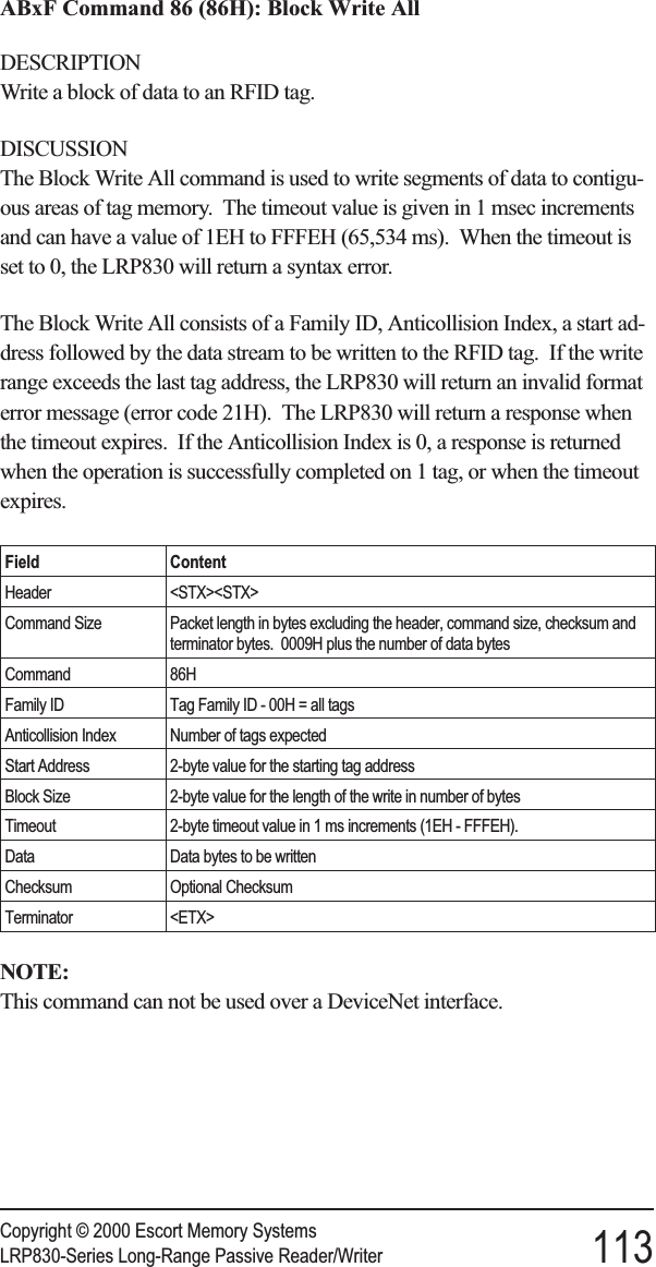
![E DEVICENET PROTOCOL EXAMPLESFor the HDR Device Type, when the DeviceNet Scanner Host has dataavailable to send to the LRP830, it must set the "REQ" bit in the DeviceNetmessage header. If the message length is 30 bytes, then the message is frag-mented and structured as follows from the master scanner. The header byteis underlined and italicized. DeviceNet Polled protocol is used.ExamplesThe following are actual DeviceNet bus message captures bySS-Technologies DeviceNet Analyzer®software. The first four examples arebased on a 30-byte message length and the last on a 28-byte message length.Generic: GEN (config display notation)Command to LRP830: Standard ABx Block WriteThis example is from the explanation of ABxS Command 5 found in Section 6.3. It will write 4 bytes ofdata to the a starting at address 0064H. A timeout of 2 seconds (07D0H = 2000 x 1 ms) is set for the com-pletion of the Block Write.MCID/MSGID Lgth Frg User Data<63>2:05 [5FD] 08 00 AA 06 00 64 00 04 07<63>2:05 [5FD] 08 41 D0 00 52 00 46 00 49<63>2:05 [5FD] 08 42 00 44 FF FF 00 00 00<63>2:05 [5FD] 08 43 00 00 00 00 00 00 00<63>2:05 [5FD] 03 84 00 00Command Response: Standard ABx Block WriteThe LRP830 will respond with a command acknowledgment as shown below, or an error message.MCID/MSGID Lgth Frg User Data<63>1:15 [3FF] 08 00 AA 06 FF FF 00 00 00<63>1:15 [3FF] 08 41 00 00 00 00 00 00 00<63>1:15 [3FF] 08 42 00 00 00 00 00 00 00<63>1:15 [3FF] 08 43 00 00 00 00 00 00 00<63>1:15 [3FF] 00 84 00 00Copyright © 2000 Escort Memory Systems178 LRP830-Series Long-Range Passive Reader/Writer](https://usermanual.wiki/Balluff/LRP800.User-Manual-Lrp830/User-Guide-132570-Page-186.png)
![Header: HDR (config display notation)Command to LRP830: Standard ABx Block ReadThis is from the explanation of ABxS Command 5 found in Section 6.3, pages 39 and 40. It reads 8bytes of data from the tag starting at address 0101H. A timeout of 2 seconds (07D0H = 2000 x 1 ms) isset for the completion of the Block Read. The REQ bit is set in the header word as shown in the first rowbelow.MCID/MSGID Lgth Frg .Hdr. User Data<63>2:05 [5FD] 08 00 02 00 AA 05 01 01 00<63>2:05 [5FD] 08 41 08 07 D0 FF FF 00 00<63>2:05 [5FD] 08 42 00 00 00 00 00 00 00<63>2:05 [5FD] 08 43 00 00 00 00 00 00 00<63>2:05 [5FD] 03 84 00 00Command Response: Standard ABx Block ReadThe LRP830 will send a response containing the bytes read as requested by the above command. In thisexample, both the ACK and the REQ bit are set in the header word as shown in the first row below.MCID/MSGID Lgth Frg .Hdr. User Data<63>1:15 [3FF] 08 00 06 00 AA 05 00 52 00<63>1:15 [3FF] 08 41 46 00 49 00 44 00 20<63>1:15 [3FF] 08 42 00 54 00 61 00 67 FF<63>1:15 [3FF] 08 43 FF 00 00 00 00 00 00<63>1:15 [3FF] 03 84 00 00Poll to LRP830This is the form of a null command from the PLC to the LRP830. No command is issued with this poll andonly the ACK bit is set in the header word.MCID/MSGID Lgth Frg .Hdr. User Data<63>2:05 [5FD] 08 00 04 00 00 00 00 00 00<63>2:05 [5FD] 08 41 00 00 00 00 00 00 00<63>2:05 [5FD] 08 42 00 00 00 00 00 00 00<63>2:05 [5FD] 08 43 00 00 00 00 00 00 00<63>2:05 [5FD] 03 84 00 00Copyright © 2000 Escort Memory SystemsLRP830-Series Long-Range Passive Reader/Writer 181](https://usermanual.wiki/Balluff/LRP800.User-Manual-Lrp830/User-Guide-132570-Page-189.png)