Balluff LRP800 Passive Tag Reader LRP820/LRP830 User Manual C transfer 1271 LRP830 vp
BALLUFF inc Passive Tag Reader LRP820/LRP830 C transfer 1271 LRP830 vp
Balluff >
Contents
- 1. User Manual Lrp820
- 2. User Manual Lrp830
User Manual Lrp830

OPERATOR'S MANUAL
LRP830-Series
Long-Range Passive
Reader/Writers
Manual Revision 3, July, ‘00
Publication #17-1271

Copyright © 2000 Escort Memory Systems
ii LRP830-Series Long-Range Passive Reader/Writer
Escort Memory Systems Warranty
Escort Memory Systems warrants that all products of its own manufacture conform to Es-
cort Memory Systems specifications and are free from defects in material and workmanship
when used under normal operating conditions and within the service conditions for which
they were furnished. The obligation of Escort Memory Systems hereunder shall expire one
(1) year after delivery, unless otherwise specified, and is limited to repairing, or at its option,
replacing without charge, any such product which in Escort Memory System's sole opinion
proves to be defective within the scope of this Warranty. In the event Escort Memory Sys-
tems is not able to repair or replace defective products or components within a reasonable
time after receipt thereof, Buyers shall be credited for their value at the original purchase
price. Escort Memory Systems must be notified in writing of the defect or nonconformity
within the warranty period and the affected product returned to Escort Memory Systems
factory or to an authorized service center within thirty (30) days after discovery of such de-
fect or nonconformity. Shipment shall not be made without prior authorization by Escort
Memory Systems.
This is Escort Memory Systems' sole warranty with respect to the products delivered here-
under. No statement, representation, agreement or understanding oral or written, made by
an agent, distributor, representative, or employee of Escort Memory Systems which is not
contained in this warranty, will be binding upon Escort Memory Systems, unless made in
writing and executed by an authorized Escort Memory Systems employee. Escort Memory
Systems makes no other warranty of any kind whatsoever, expressed or implied, and all im-
plied warranties of merchantability and fitness for a particular use which exceed the
aforestated obligation are hereby disclaimed by Escort Memory Systems and excluded
from this agreement. Under no circumstances shall Escort Memory Systems be liable to
Buyer, in contract or in tort, for any special, indirect, incidental, or consequential damages,
expenses, losses or delay however caused.
Equipment or parts which have been subject to abuse, misuse, accident, alteration, ne-
glect, unauthorized repair or installation are not covered by warranty. Escort Memory Sys-
tems shall make the final determination as to the existence and cause of any alleged defect.
No liability is assumed for expendable items such as lamps and fuses. No warranty is made
with respect to custom equipment or products produced to Buyer's specifications except as
specifically stated in writing by Escort Memory Systems in the contract for such custom
equipment.
This warranty is the only warranty made by Escort Memory Systems with respect to the
goods delivered hereunder, and may be modified or amended only by a written instrument
signed by a duly authorized officer of Escort Memory Systems and accepted by the Buyer.
Extended warranties of up to four years are available for purchase for most EMS products.
Contact EMS or your distributor for more information.
This document contains proprietary information which is protected by copyright. All rights are re-
served. The information in this manual has been carefully checked and is believed to be accu-
rate; however, no responsibility is assumed for possible inaccuracies or omissions.
Specifications are subject to change without notice.
EMS®, Escort Memory Systems® and the EMS® logo are registered trademarks of Escort
Memory Systems, a Datalogic Group Company. Other brand and product names mentioned are
trademarks or registered trademarks of their respective holders.
Escort Memory Systems
A Datalogic Group Company
170 Technology Circle
Scotts Valley, CA 95066
Telephone (831) 438-7000
FAX (831) 438-5768
www.ems-rfid.com
email: info@ems-rfid.com

Copyright © 2000 Escort Memory Systems
LRP830-Series Long-Range Passive Reader/Writer iii
TABLE OF CONTENTS
1GETTING STARTED 1
1.1 Introduction.........................1
1.2 Unpacking and Inspection .................3
2MECHANICAL SPECIFICATIONS 4
2.1 Dimensions .........................4
2.2 RF Range and Orientation .................7
2.3 Mounting Guidelines ...................12
Guidelines .........................13
3POWER AND ELECTRICAL INTERFACE 14
3.1 Connector Panel ......................14
3.2 Power Connector .....................15
3.3 COM1/COM2 Connector .................15
Serial Communications Cabling .............16
3.4 DeviceNet Connector ...................16
3.5 Input Connector ......................17
3.6 Output Connector .....................17
3.7 Digital I/O Wiring.....................18
Inputs ...........................18
Outputs ..........................18
3.8 Power Requirement ....................23
Power Options.......................23
Power from the DeviceNet Bus ..............24
Power via the external supply connector .........24
Power from the DeviceNet bus and from an external power
supply ...........................26
3.9 LED Indicators ......................27
4SERIAL AND BUS COMMUNICATIONS 29
4.1 Serial Interfaces ......................29
Digital Board DIP Switch .................30
4.2 Bus Interfaces .......................32
DeviceNet Interface Board DIP Switch .........33

Copyright © 2000 Escort Memory Systems
iv LRP830-Series Long-Range Passive Reader/Writer
5MENU CONFIGURATION 35
5.1 How to Enter Menu Configuration ............35
5.2 Set-up Operating Parameters ...............36
Set COM1 Parameters...................37
Set COM2 Parameters...................37
Set Operating Mode ....................37
Set RF Communication ..................39
Restore Factory Defaults .................39
Return to Main Menu ...................40
5.3 Download New Program .................40
5.4 Downloading DSP Firmware ...............40
5.5 Exit to Operating Mode ..................41
6 RFID INTERFACE 42
6.1 Introduction ........................42
Command Timeout ....................42
DeviceNet and Anticollision ABx Limitations ......44
6.2 ABx Error Codes .....................45
Non-Anticollision Error Codes ..............45
ABx Standard .......................45
ABx Fast .........................46
Anticollision Status Byte .................47
6.3 Anticollision Commands .................48
Family Interrogation ...................48
Family ID .........................48
Anticollision Index ....................49
6.4 ABx Standard Protocol ..................51
ABxS Command 4 (04H): Fill Tag ............51
ABxS Command 5 (05H): Block Read ..........53
ABxS Command 6 (06H): Block Write..........55
ABxS Command 7 (07H): Read Tag Serial Number . . . 57
ABxS Command 8 (08H): Tag Search ..........58
ABxS Command D (0DH): Continuous Block Read . . . 59
ABxS Command 10 (10H): Set Output ..........62
ABxS Command 11 (11H): Input Status .........64
ABxS Command 84 (84H): Fill Tag All .........66
ABxS Command 85 (85H): Block Read All .......68
ABxS Command 86 (86H): Block Write All .......70
ABxS Command 87 (87H): Read Tag SN All ......72

Copyright © 2000 Escort Memory Systems
LRP830-Series Long-Range Passive Reader/Writer v
ABxS Command 88 (88H): Tag Search All .......74
ABxS Command 89 (89H): EAS Set/Reset All......75
ABxS Command 8A (8AH): EAS Start/Stop .......76
ABxS Command 8D (8DH): Continuous Read All ....78
ABxS Command 8E (8EH): Memory Lock All......80
ABxS Command 94 (94H): SN Fill............82
ABxS Command 95 (95H): SN Block Read ......84
ABxS Command 96 (96H): SN Block Write .......86
ABxS Command 97 (97H): SN Block Read All .....88
6.5 ABx Fast Protocol.....................90
ABx Command Packet Structure: .............90
Command/Response Size .................91
Checksum .........................92
ABxF Command 4 (04H): Fill Tag ............93
ABxF Command 5 (05H): Block Read ..........95
ABxF Command 6 (06H): Block Write..........97
ABxF Command 7 (07H): Read Tag Serial Number . . . 99
ABxF Command 8 (08H): Tag Search .........101
ABxF Command D (0DH): Continuous Block Read . . 102
ABxF Command 10 (10H): Set Output .........105
ABxF Command 11 (11H): Input Status ........107
ABxF Command 84 (84H): Fill All ...........109
ABxF Command 85 (85H): Block Read All.......111
ABxF Command 86 (86H): Block Write All ......113
ABxF Command 87 (87H): Read Tag SN All......115
ABxF Command 88 (88H): Tag Search All .......117
ABxF Command 89 (89H): EAS Set/Reset All .....119
ABxF Command 8A (8AH): EAS Start/Stop ......121
ABxF Command 8D (8DH): Continuous Read All . . . 124
ABxF Command 8E (8EH): Memory Lock All .....127
ABxF Command 94 (94H): SN Fill ...........130
ABxF Command 95 (95H): SN Block Read ......132
ABxF Command 96 (96H): SN Block Write ......134
ABxF Command 97 (97H): SN Block Read All.....136
6.6 ABx ASCII Protocol ...................140
Command Packet Structure: ...............140
Command/Response Size ................141
Checksum ........................142
Example ASCII Command ...............142

Copyright © 2000 Escort Memory Systems
vi LRP830-Series Long-Range Passive Reader/Writer
7 LRP830 DEVICENET INTERFACE 144
7.1 Introduction .......................144
Scan Rates ........................144
COM1 LED Indicator ..................145
DeviceNet Interface ...................145
7.2 Interface Board Monitor Mode .............145
Enter Interface Board Monitor..............145
7.2.1 Downloading Firmware to the Interface Board .....147
7.2.2 Downloading with the EC Emulation Program .....148
7.2.3 Display Interface Board Configuration Parameters . . . 148
7.2.4 Interface Board Configuration Editor ..........150
7.2.5 Edit Configuration Command. ..............151
7.2.6 Configuration Parameter Validation ...........153
7.2.7 Standard DeviceNet Parameters .............154
Produce and Consume Sizes ...............154
Produce size — ABx Standard, 8 Byte Read ......154
Produce size — ABx Fast, 8 Byte Read ........155
Consume size — ABx Standard, 8 Byte Read .....155
Consume size — ABx Fast, 8 Byte Read ........156
LRP830 Transmit Message Size .............156
LRP830 Receive Message Size .............157
Protocol: Poll or Strobe .................157
DeviceNet Serial Number ................157
7.2.8 LRP830 Specific Parameters ..............158
Device Type .......................158
ABx separation......................158
ABx Non-separation ...................158
Polled Commands in ABx Non-separation Mode ....159
Error Management ....................159
Trigger Feature .....................160
Buf Flush Enable.....................161
Buf Flush Delay .....................161
7.2.9 Device Type Protocols. .................162
Generic Device Type Protocol..............162
Header Device Type Protocol ..............163

Copyright © 2000 Escort Memory Systems
LRP830-Series Long-Range Passive Reader/Writer vii
ASPECIFICATIONS 165
BMODELS AND ACCESSORIES 166
C ASCII CHART 168
D LRP830 DEMONSTRATION 170
Before You Begin ....................170
Using DNSW32 or DNSW16 ..............171
EDEVICENET PROTOCOL EXAMPLES 178
Header Device Type Protocol ..............179
Header Format ......................179
Header Device Type Command Protocol ........182
Calculating Message Size ................183

Copyright © 2000 Escort Memory Systems
viii LRP830-Series Long-Range Passive Reader/Writer
NOTICE
This equipment has been tested and found to comply with the limits for a
Class B digital device, pursuant to Part 15 of the FCC Rules. These limits
are designed to provide reasonable protection against harmful interference in
a residential installation. This equipment generates, uses and can radiate ra-
dio frequency energy and, if not installed and used in accordance with the in-
structions, may cause harmful interference to radio communications.
However, there is no guarantee that interference will not occur in a particular
installation. If this equipment does cause harmful interference to radio or
television reception, which can be determined by turning the equipment off
and on, the user is encouraged to try and correct the interference by one or
more of the following measures:
nReorient or relocate the receiving antenna.
nIncrease the separation between the equipment and the re-
ceiver.
nConnect the equipment into an outlet on a circuit different
from that to which the receiver is connected.
nConsult the dealer or an experienced radio/TV technician for
help.
CAUTION
Changes or modifications not expressly approved by Escort Memory Sys-
tems could void the user’s authority to operate the equipment.

1 GETTING STARTED
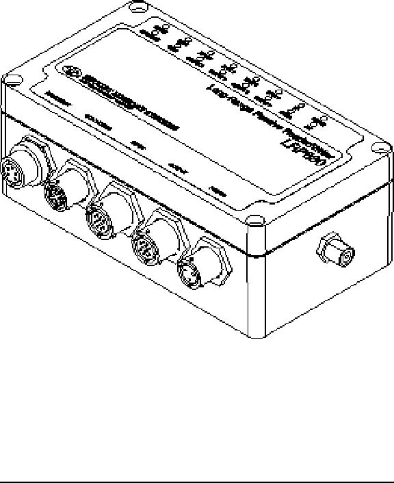
1.1 Introduction
Escort Memory Systems' passive read/write system is a complete family of
field-proven read/write Radio-Frequency Identification products. The sys-
tem consists of RFID tags, reader/writers, antennas, controllers, bus inter-
faces, and ancillary equipment. Tags can be attached to a product or its
carrier and act as an electronic identifier, job sheet, portable database, or
manifest. Tags are read and updated via an Escort Memory Systems
Reader/Writer, through any nonconductive material, while moving or stand-
ing still.
Escort Memory Systems' LRP-Series long-range passive RFID system is the
latest in our line of high performance, industrial RFID equipment. The pas-
sive design of the LRP read/write system uses the RF field from the antenna
to power the tag, eliminating the need for tag batteries. The LRP passive
read/write system is designed to provide cost effective RFID data collection
and control solutions to automation and material handling applications.
The LRP system uses the internationally recognized ISM frequency of 13.56
MHZ to both power the tag, and to establish a radio link to transfer the infor-
mation.
The LRP830 is specifically designed to work with LRP-Series passive tags,
which provide 48 bytes of reprogrammable memory.
Copyright © 2000 Escort Memory Systems
LRP830-Series Long-Range Passive Reader/Writer 1
The LRP830 supports the industrial bus protocol DeviceNet. The LRP830
is encased in a NEMA4 enclosure and features two serial ports, 4 opto-
isolated inputs, 4 opto-isolated outputs. The LRP830-04 is equipped with
an antenna designed for conveyor mounting and the LRP830-08 features a
rectangular plate antenna.
The COM1 serial port is used to receive commands from the host and to
send the data back. The LRP830 COM1 can be configured either as a
DeviceNet, RS232, or RS422 interface.
COM2 is an RS232 serial port used to download new software releases and
to setup the configuration parameters.
Copyright © 2000 Escort Memory Systems
2LRP830-Series Long-Range Passive Reader/Writer

1.2 Unpacking and Inspection
Unpack the LRP830 and documentation and retain the original shipping
carton and packing material in case any items need to be returned. Inspect
each item carefully for evidence of damage. If any item appears to be dam-
aged, notify your distributor immediately. The LRP830 is delivered with the
following components:
nLRP830 (-04, -08) Reader/Writer
nLRP830 to Antenna Cable
nLRP830 Operator's Manual
The following components are required for configuring a complete system:
nLRP-Series Passive Read/Write Tags
nUser supplied LRP830-to-host cable
nDeviceNet host
n18 - 30 Vdc, 36 W (1.5 A @ 24 Vdc) power supply
nMating connectors. Please see Appendix B for more
information.
Copyright © 2000 Escort Memory Systems
LRP830-Series Long-Range Passive Reader/Writer 3
2 MECHANICAL SPECIFICATIONS
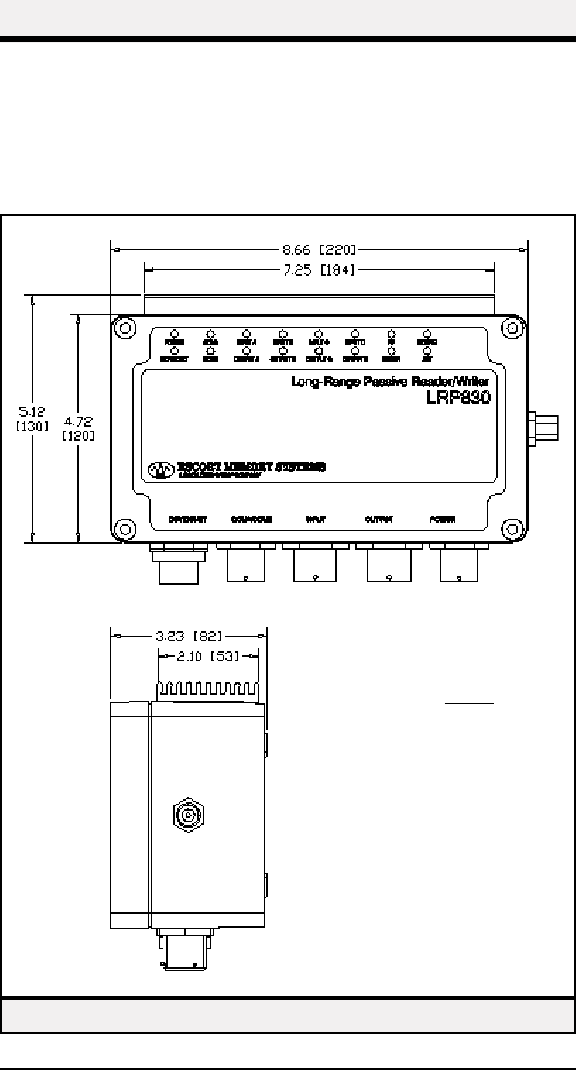
2.1 Dimensions
Figure 1 gives the dimensions for the LRP830. Figures 2-3 show the dimen-
sions of the 04 and 08 remote antennas.
Copyright © 2000 Escort Memory Systems
4LRP830-Series Long-Range Passive Reader/Writer
Figure 1 — LRP830 Dimensions
inches
mm
Copyright © 2000 Escort Memory Systems
LRP830-Series Long-Range Passive Reader/Writer 5
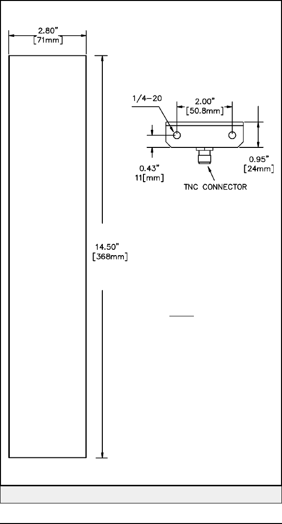
Figure 2 — LRP-04 Conveyor-Mount Antenna
inches
mm
Copyright © 2000 Escort Memory Systems
6LRP830-Series Long-Range Passive Reader/Writer
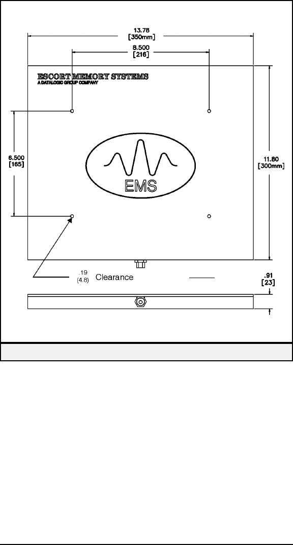
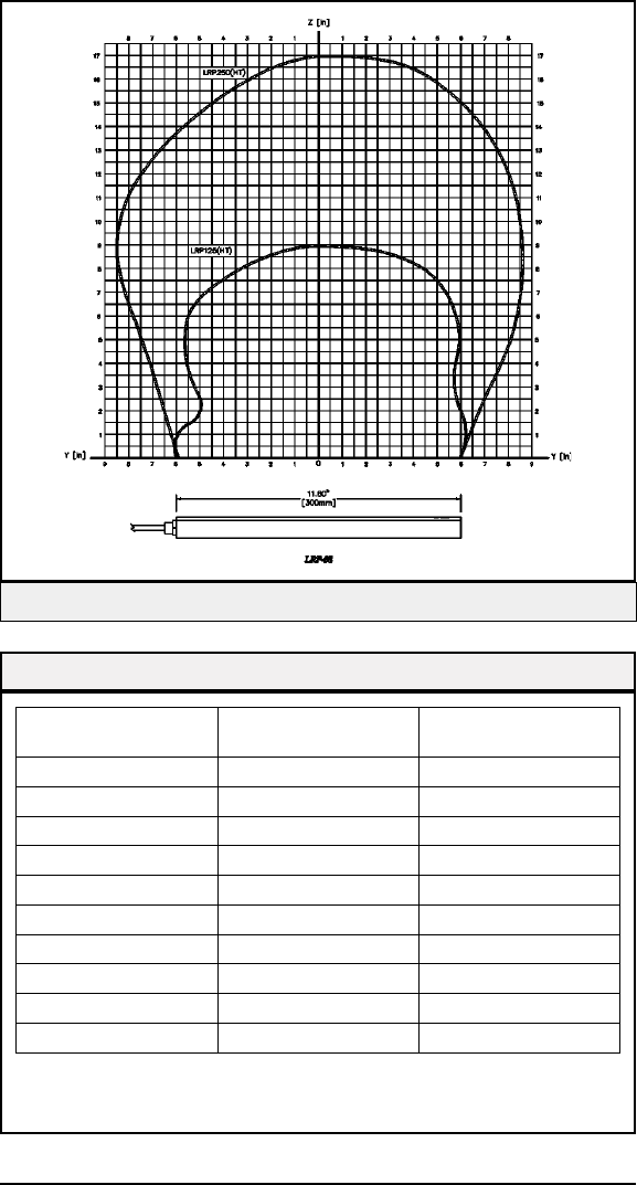
Figure 3 — LRP-08 Antenna Dimensions
inches
mm
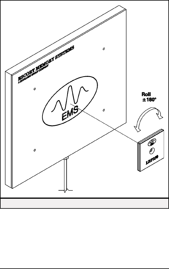
2.2 RF Range and Orientation
Figure 4 shows the correct tag orientation as it passes the antenna. Figures
5-7 show the RF fields of the LRP830-04 and LRP830-08 antennas. Tables
1- 3 give the typical and guaranteed ranges of the LRP series tags.
Copyright © 2000 Escort Memory Systems
LRP830-Series Long-Range Passive Reader/Writer 7
Figure 4 — LRP-08 to Tag Orientation
Copyright © 2000 Escort Memory Systems
8LRP830-Series Long-Range Passive Reader/Writer
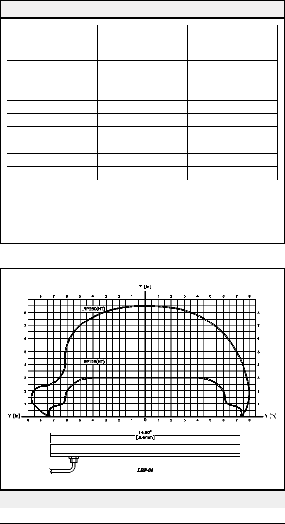
Figure 5 — Side View of RF Field, LRP-04 Antenna, Metal
Tag Typical Range (Z)
inches/mm
Guaranteed Range
inches/mm
LRP125(HT) 2.50/64 2.00/51
LRP250(HT) 6.75/171 6.00/152
LRP250HT-FLX 6.75/171 6.00/152
LRP-L5555 6.75/171 6.00/152
LRP-L2666 5.75/146 5.00/127
LRP-L4982 8.00/203 7.00/178
LRP-L90140 9.00/229 8.00/203
LRP-P125 2.50/64 2.00/51
LRP-P3858 6.00/152 5.00/127
LRP-P5050 7.00/178 6.00/152
*These ranges are determined with metal near the -04 antenna as it would be in most conveyor
mountings. The actual tuning and testing of the -04 antenna is done with the antenna mounted be-
tween two metal rollers on metal rails. The metal rollers are mounted 1/4” from the antenna.
NOTE: Proximity to metal, CRT devices, and other sources of electromagnetic radiation may affect
the range of the antenna.
Table 1 — Antenna to Tag Ranges, LRP-04 Antenna with Metal*
Copyright © 2000 Escort Memory Systems
LRP830-Series Long-Range Passive Reader/Writer 9
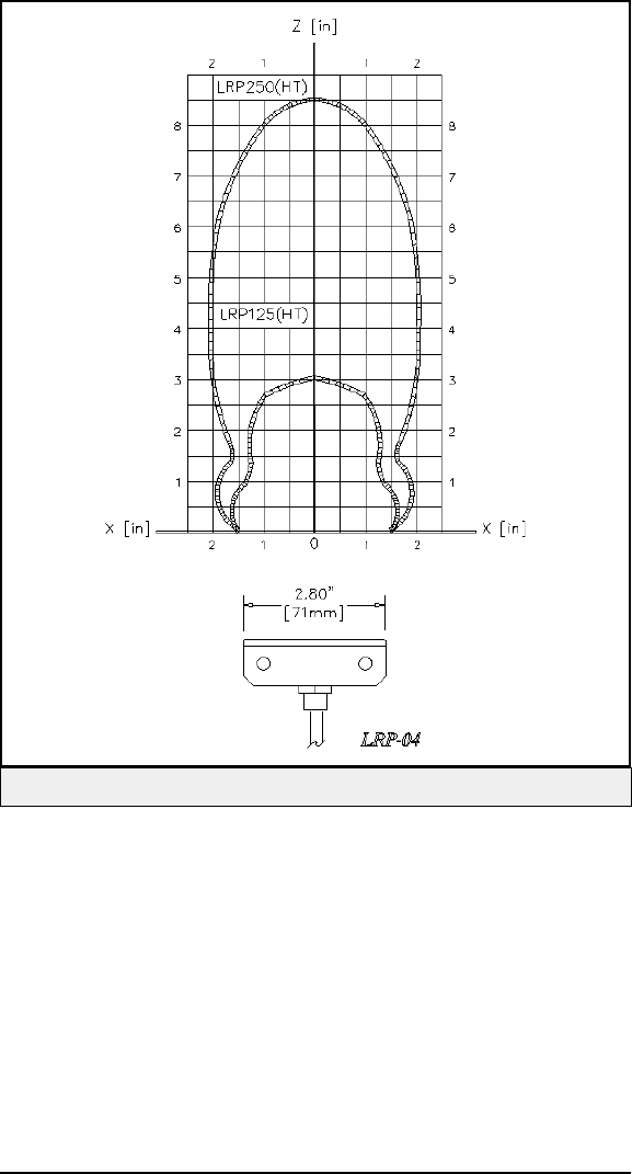
Figure 6 — End View of RF Field, LRP-04 Antenna, Metal
Copyright © 2000 Escort Memory Systems
10 LRP830-Series Long-Range Passive Reader/Writer
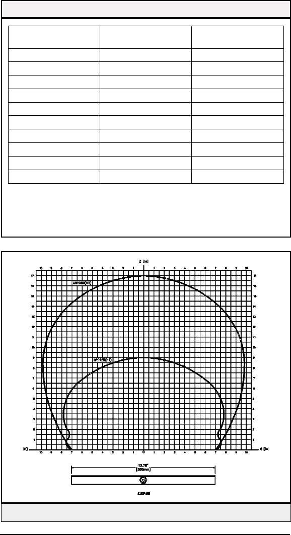
Figure 7 — End View of RF Field, LRP-08 Antenna, No Metal
Tag Typical Range (Z)
inches/mm
Guaranteed Range
inches/mm
LRP125(HT) 3.00/76 2.25/57
LRP250(HT) 8.50/216 7.50/191
LRP250HT-FLX 8.50/216 7.50/191
LRP-L5555 8.50/216 7.50/191
LRP-L2666 7.00/178 6.00/152
LRP-L4982 10.00/254 9.00/229
LRP-L90140 12.00/305 11.00/279
LRP-P125 3.00/76 2.25/57
LRP-P33858 7.50/190 6.50/165
LRP-P5050 8.50/216 7.50/191
*These ranges calculated with no metal near the antenna.
NOTE: Proximity to metal, CRT devices, and other sources of electromagnetic radiation may affect
the range of the antenna.
Table 2 — Antenna to Tag Ranges, LRP-40 Antenna, No Metal*
Copyright © 2000 Escort Memory Systems
LRP830-Series Long-Range Passive Reader/Writer 11
Tag Typical Range (Z)
inches/mm
Guaranteed Range
inches/mm
LRP125(HT) 8.00/203 7.00/178
LRP250(HT) 17.00/432 15.00/381
LRP250HT-FLX 17.00/432 15.00/381
LRP-L5555 17.00/432 15.00/381
LRP-L2666 16.00/406 13.00/330
LRP-L4982 20.00/508 18.00/457
LRP-L90140 25.00/635 22.00/559
LRP-P125 8.00/203 7.00/178
LRP-P3858 16.00/406 14.00/355
LRP-5050 17.00/432 15.00/381
*These ranges calculated with no metal near the antenna.
NOTE: Proximity to metal, CRT devices, and other sources of electromagnetic radiation may affect
the range of the antenna.
Table 3 — Antenna to Tag Ranges, LRP-08 Antenna, No Metal
Figure 8 — Side View of RF Field, LRP-08 Antenna, No Metal
2.3 Mounting Guidelines
Electromagnetic radiation and metal affect the range of the LRP830. Mount
the LRP830 and antenna to minimize the impact of these factors. The RF
field of the antenna can also cause errors when antennas are spaced too
closely together. Do not position adjacent antennas closer than 2 meters from
each other.
The remote antennas for the LRP830 have a cable length 2 meters. Sur-
rounding the antenna with metal will greatly reduce the reading range of the
antenna. As rule of thumb, keep any metal structure away from the antenna
at least more than the reading range along the axis, and a third of such dis-
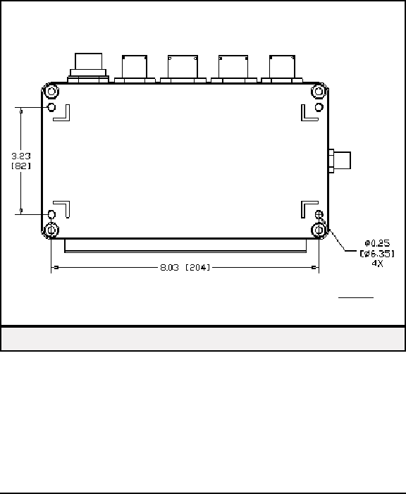
tance on the side. The mounting holes are accessed through the inside of the
LRP830 Reader/Writer. Refer to Figure 9 for locations and dimensions.
Copyright © 2000 Escort Memory Systems
12 LRP830-Series Long-Range Passive Reader/Writer
Figure 9 — LRP830 Mounting Holes
inches
mm
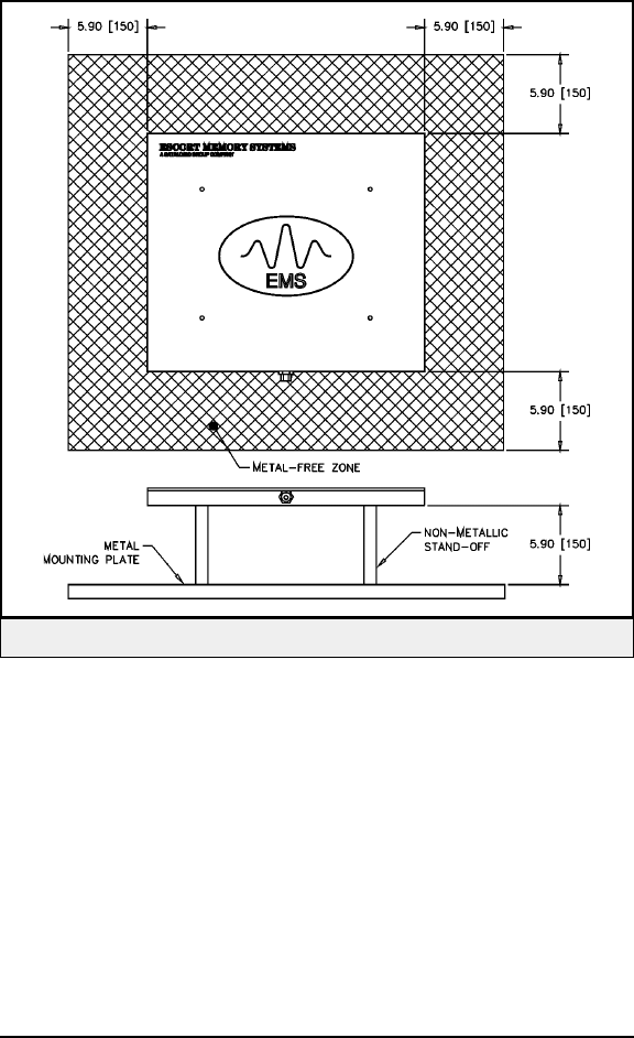
Special mounting instructions must be followed to get optimal read/write
performance from the LRP830-08 antenna. Mount the antenna with a mini-
mum 5.90" (150mm) spacing from any metal to the back or sides of the an-
tenna, as shown in Figure 10.
Guidelines
nIsolate the LRP830 and antenna from electromagnetic
radiation.
nAvoid surrounding LRP830 and remote antenna with metal.
nMaintain at least 2 meters minimum spacing between adjacent
LRP830s or antennas.
nStay within the guaranteed range for the tag to be used.
nConform with EIA RS232, RS422 and RS485 standards.
Copyright © 2000 Escort Memory Systems
LRP830-Series Long-Range Passive Reader/Writer 13
Figure 10 — LRP830-08 Antenna Mounting
3 POWER AND ELECTRICAL INTERFACE
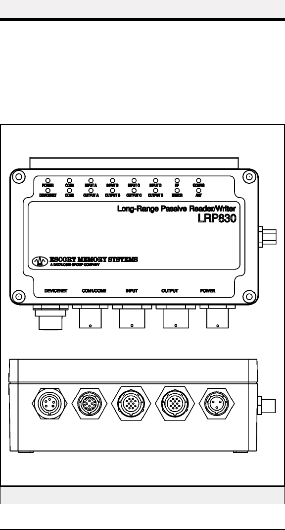
3.1 Connector Panel
Figure 11 shows the LRP connectors, LEDs and connector panel. Unused
connectors can be sealed with optional connector caps. Please see Appendix
B for ordering information.
Copyright © 2000 Escort Memory Systems
14 LRP830-Series Long-Range Passive Reader/Writer
Figure 11 — Connector Panel
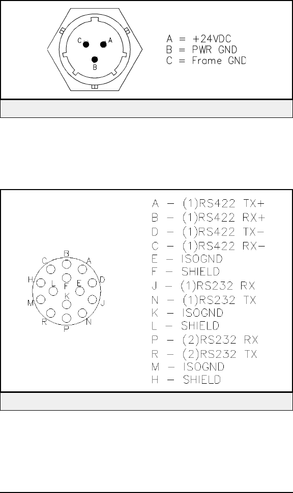
3.2 Power Connector
Figure 12 shows the power connector pin designations.
3.3 COM1/COM2 Connector
Figure 13 shows the connector pin designations for the COM port connec-
tions.
Copyright © 2000 Escort Memory Systems
LRP830-Series Long-Range Passive Reader/Writer 15
Figure 12 — Power Connector
Figure 13 — COM1/COM2 Connector
Serial Communications Cabling
Escort Memory Systems recommends that you use Belden cables 3082A
(trunkline) or 3084A (dropline) for RS485/RS422 communications. Use
Belden cable 9941 for RS232 communications. More information on Belden
cables can be found on their web site at www.belden.com.
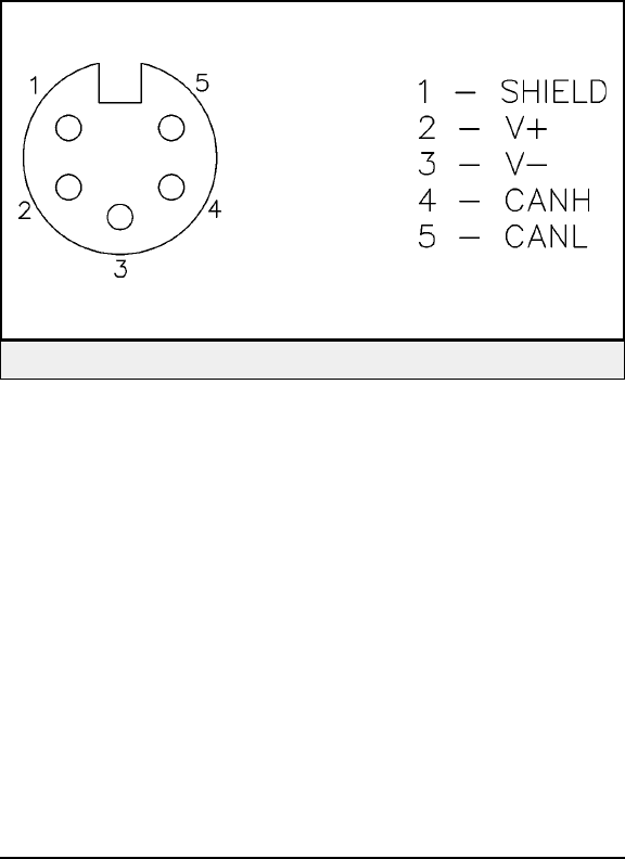
3.4 DeviceNet Connector
Figure 14 shows the connections for the DeviceNet connector.
Copyright © 2000 Escort Memory Systems
16 LRP830-Series Long-Range Passive Reader/Writer
Figure 14 — DeviceNet Connector Pinouts
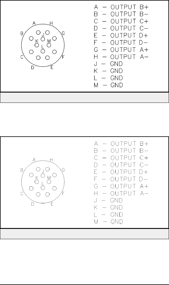
3.5 Input Connector
Figure 15 shows the Input Connector pin designations.
3.6 Output Connector
Figure 16 shows the Output Connector pin designations.
Copyright © 2000 Escort Memory Systems
LRP830-Series Long-Range Passive Reader/Writer 17
Figure 15 — Input Connector Pinouts
Figure 16 — Output Connector Pinouts

3.7 Digital I/O Wiring
Both the Digital Inputs and Digital Outputs are optically isolated circuits
with no common path between any channel terminal and another channel, or
between any channel and the LRP830 power. Because they are independent
and floating, the external wiring controls their use. The inputs can be config-
ured for sensors with a PNP or NPN output. The outputs can be configured
in a Sourcing or Sinking configuration. The examples in Figures 17 through
24 show different connections for common input and output devices.
Inputs
The +IN terminal must be at a higher positive potential than the -IN terminal
for current to be sensed correctly. The voltage range is 4.5 to 30V between
the +IN and the -IN inputs and the maximum current is 25 mA.
Outputs
The output is limited to 30Vdc when off and 500 mA. These are maximum
ratings. A device that operates at 200 mA may destroy the output due to in-
rush current if that current exceeds 500 mA (e.g. an incandescent light). The
inductive "kick" (back EMF from a collapsing magnetic field) when a relay
is released can impose a voltage higher than 30V and destroy the output
transistor (use a backwards diode to clamp the back EMF).
Copyright © 2000 Escort Memory Systems
18 LRP830-Series Long-Range Passive Reader/Writer
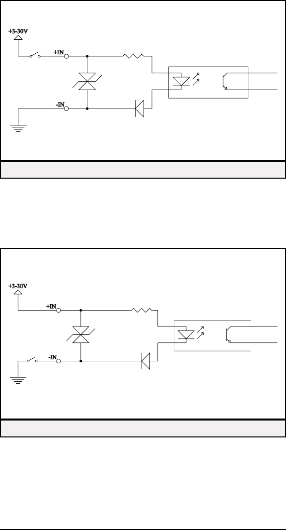
Figure 17 shows the switch on the high side with the low side grounded. As
this is a "Dry" contact (the current is limited to 15 mA) a high quality sealed
switch should be used.
Figure 18 shows a switch connected on the low side with the high side con-
nected to the positive supply. This also requires a high quality sealed contact.
Copyright © 2000 Escort Memory Systems
LRP830-Series Long-Range Passive Reader/Writer 19
Figure 17 — Input from Sourcing Contact
Figure 18 — Input from Sinking Contact
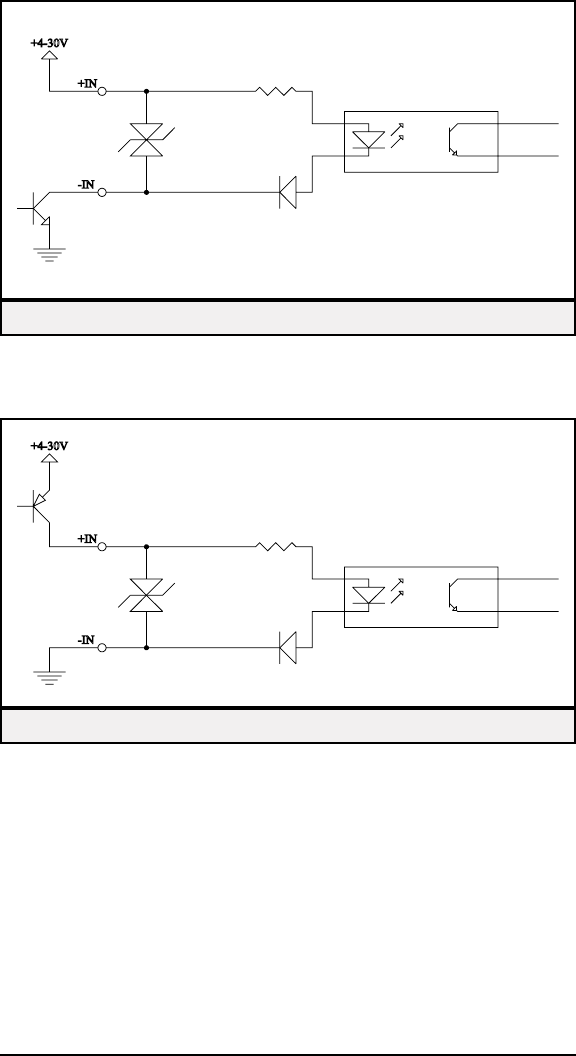
Figure 19 shows an Open Collector NPN output from a photosensor switch-
ing to ground. It can be wired as a sinking or low-side contact.
Figure 20 shows an Open Collector PNP output from a photosensor
switches to the positive supply. It can be wired as a sourcing or high-side
contact.
Copyright © 2000 Escort Memory Systems
20 LRP830-Series Long-Range Passive Reader/Writer
Figure 20 — Input from PNP Sensor
Figure 19 — Input from NPN Sensor
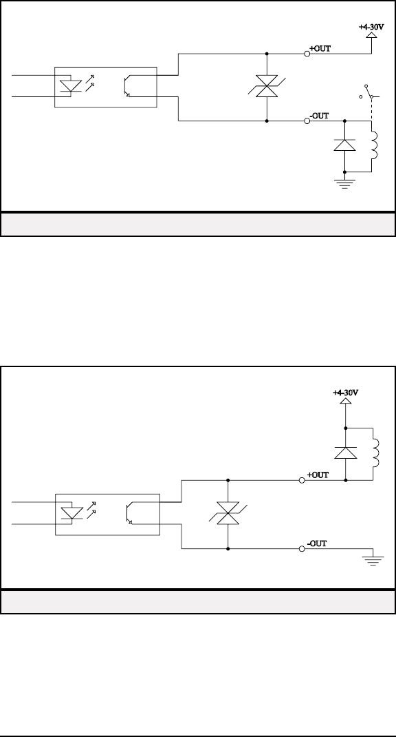
Figure 21 shows a relay connected as a current sourcing "Contact." The re-
lay is grounded and the +OUT terminal goes to the positive supply. The di-
ode across the relay coil is essential to protect the output circuit and reduce
noise along the wiring. It should be connected at the relay to minimize the
length of wiring that could radiate noise. A 1N4001 or similar diode may be
used.
Figure 22 shows a "Contact" sinking current from a relay, the -OUT terminal
is grounded and the relay goes to the positive supply. This configuration
must also have a diode across the relay coil to protect the circuit and reduce
noise.
Copyright © 2000 Escort Memory Systems
LRP830-Series Long-Range Passive Reader/Writer 21
Figure 22 — Sinking Output "Contact"
Figure 21 — Sourcing Output "Contact"
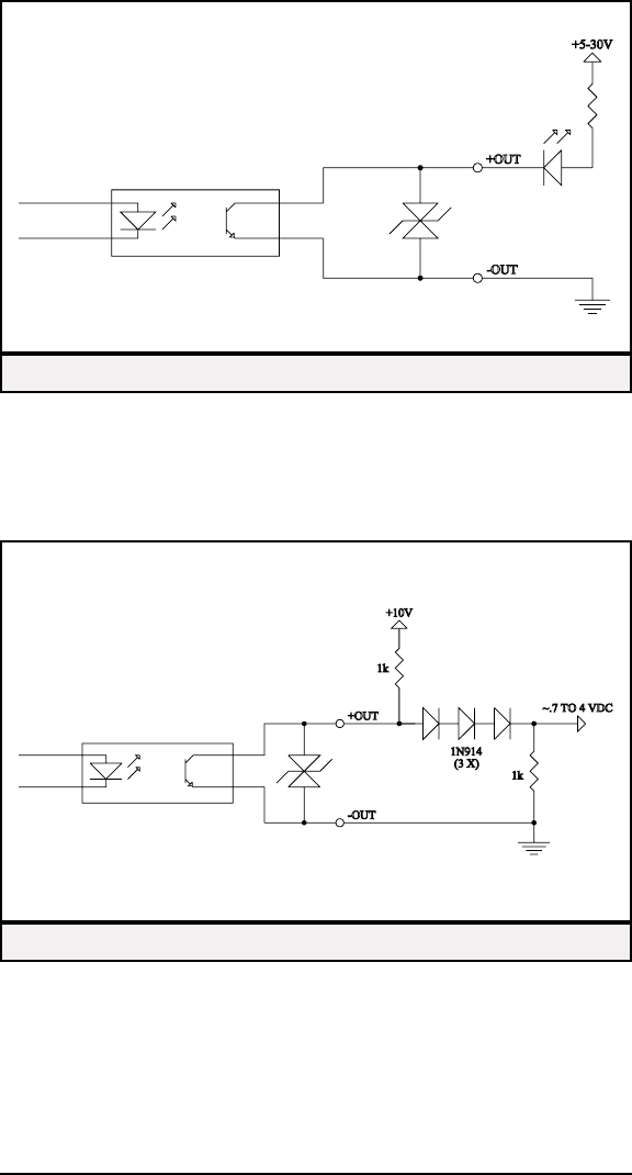
In Figure 23, the LED and current limiting resistor are in series between the
positive supply and the +OUT terminal. The -OUT terminal is grounded.
The resistor in series with the LED sets the forward current. 1.2K will pro-
vide 20 mA LED current when run from 24 Vdc.
In Figure 24 the output acts as an Open Collector. This will provide a TTL
or CMOS compatible signal when a 1K to 10K pull-up to +5 Vdc (the logic
supply) is used.
Copyright © 2000 Escort Memory Systems
22 LRP830-Series Long-Range Passive Reader/Writer
Figure 23 — Sinking Output LED Driver
Figure 24 — Output to TTL or CMOS

3.8 Power Requirement
The LRP830 power supply requirement are:
n18 to 30Vdc
n31W maximum power consumption.
The maximum current consumption at 24Vdc is 1.3 A.
Power Options
There are three options for powering the LRP830:
nPowered from the DeviceNet Bus (default)
This is the default configuration for powering the LRP830. If the
power available over your DeviceNet network is not sufficient to
power the LRP830, use one of the following methods.
nPowered via the external power connector
This is how you must power the LRP830 if you are not connecting
the LRP830 to a DeviceNet network.
nPowered from an external supply and isolated DeviceNet bus
power (isolated mode)
When the LRP is powered from both sources, the LRP830 will be
opto-isolated from the DeviceNet bus.
The DeviceNet interface board draws 20 mA at 24 Vdc from the
DeviceNet bus when the LRP830 is powered with this method.
Power to the external power connector should conform to the spec-
ifications given above.
If you choose to power the LRP830 with an external supply via the power
connector, you must open the LRP830 and changed jumper and cable loca-
tions. The following sections describe how to make these changes.
Copyright © 2000 Escort Memory Systems
LRP830-Series Long-Range Passive Reader/Writer 23
Power from the DeviceNet Bus
By default, the LRP830 is configured to run with power supplied by the net-
work. In this mode, there is no galvanic isolation between the DeviceNet
wires and the LRP830, and there is no need for a separate power supply.
If you choose to power the LRP830 form the DeviceNet bus, you do not
need to make any internal changes to cables and jumpers. Wire power ac-
cording to the pinouts given for the DeviceNet connector in Figure 14, page
16.
Power via the external supply connector
The LRP830 contains components sensitive to electro-static discharge. Take
proper grounding precautions before opening the LRP830.
To change the LRP830 to run in isolated mode:
1. Open the LPR820 by loosening the four captive screws that se-
cure the cover.
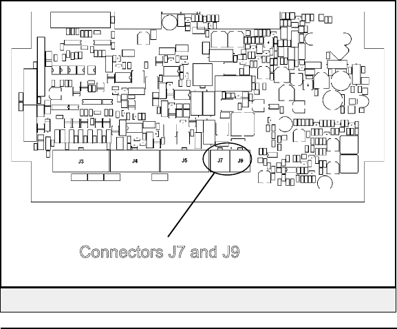
2. Refer to Figure 25 and then move the power cable, labeled assem-
bly 10-3110, from connector J7 to J9.
Copyright © 2000 Escort Memory Systems
24 LRP830-Series Long-Range Passive Reader/Writer
Figure 25 — Power Cable Connectors J7 andJ9
3. The DeviceNet cable, labeled assembly 10-3116, must then ex-
change places with the power cable, moving from J9 to J7.
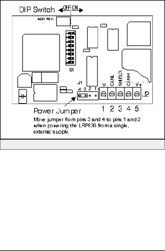
4. Referring to Figure 26, locate jumper J1 and move the shunt from
pins 4 and 3 to pins 2 and 1.
5. Close the LRP830 and connect a separate +24V power supply to
the external power connector shown in Figure 12, page 15.
Copyright © 2000 Escort Memory Systems
LRP830-Series Long-Range Passive Reader/Writer 25
Figure 26 — DeviceNet Board Power Jumper

Power from the DeviceNet bus and from an external power supply
When the LRP is powered from both sources, the LRP830 will be
opto-isolated from the DeviceNet bus.
The LRP830 contains components sensitive to electro-static discharge. Take
proper grounding precautions before opening the LRP830.
To power the LRP830 from an external supply and the DeviceNet bus:
1. Open the LPR820 by loosening the four captive screws that
secure the cover.
2. Refer to Figure 25 and then move the power cable, labeled assem-
bly 10-3110, from connector J7 to J9.
3. The DeviceNet cable, labeled assembly 10-3111, must then
exchange places with the power cable, moving from J9 to J7.
4. Make sure that the jumper on J1of the DeviceNet Interface Board
connects pins 3 and 4, and then close the LRP830.
5. Connect a separate +24V power supply to the external power
connector shown in Figure 12, page 15.
6. Wire the DeviceNet interface and power according to the pinouts
given for the DeviceNet connector in Figure 14, page 16.
Copyright © 2000 Escort Memory Systems
26 LRP830-Series Long-Range Passive Reader/Writer
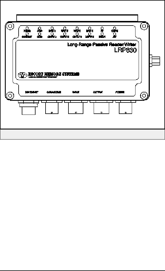
3.9 LED Indicators
The LRP830 has 16 LEDs indicating status of the LRP830 Reader/Writer,
interface communications, and I/O status.
Copyright © 2000 Escort Memory Systems
LRP830-Series Long-Range Passive Reader/Writer 27
Figure 27 — LRP830 Front with LEDs

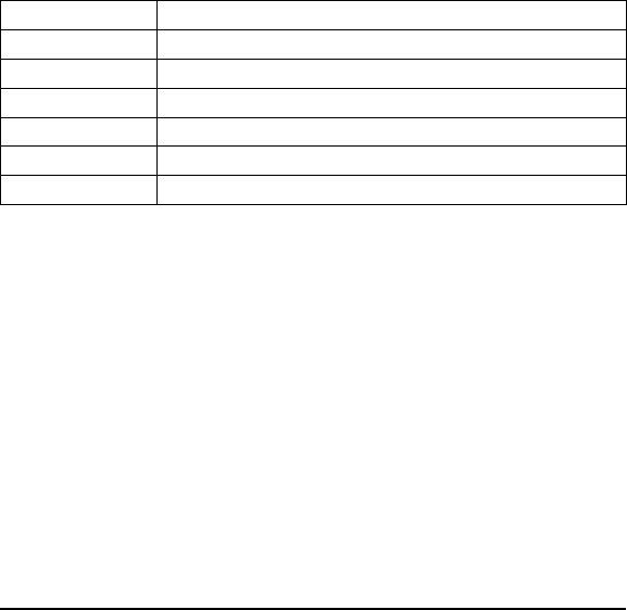
Table 4 shows these LEDs and their meaning.
Additional LED behavior may be observed during certain commands and
conditions. This behavior will be indicated as appropriate elsewhere in this
manual.
Copyright © 2000 Escort Memory Systems
28 LRP830-Series Long-Range Passive Reader/Writer
LED Color Indicates
PWR red The LRP830 is receiving power
RF green RF Data Transfer
ANT red Antenna on and tag in field
ERROR Red Unsuccessful RF command (.5 sec. flash)
Entering Download Mode via DIP switch 5 (4 flashes)
CONFIG green Successful RF command-1.5sec. flash
ERROR +
CONFIG
green/red Entering Operating Mode - 4 alternate flashes
Configuration Mode initiated (CTRL-D) - Both LEDS flash 4 times
Configuration Mode initiated (CTRL-E) - Both LEDS flash 2 times
IN-A yellow Input active
IN-B yellow Input active
IN-C yellow Input active
IN-D yellow Input active
COM1 green/red Incoming data (RX): red
Outgoing data (TX): green
COM2 green/red Incoming data (RX): red
Outgoing data (TX): green
DeviceNet red Data transfer (RX/TX): red
OUT-A green Output active
OUT-B green Output active
OUT-C green Output active
OUT-D green Output active
Table 4 — LED Indicators

4 SERIAL AND BUS COMMUNICATIONS
4.1 Serial Interfaces
The LRP830 has RS232 and RS422 available on the COM1 serial port.
COM2 is configured for RS232 communications and is reserved for down-
loading programs to the LRP830 and for setting up the configuration
parameters.
Both RS232 and RS422 interfaces are opto-isolated. The RS422 interface
is specially suitable for long cable, noisy environment links.
The specification for the COM1 interface follows:
nBaud rate: 1200, 2400, 4800, 9600, 19200, 38400 bps
nData: 7, 8
nParity: Even, Odd, None
nHandshake: None, Xon/Xoff
The specification for the COM2 interface follows:
nBaud rate: 1200, 2400, 4800, 9600, 19200 bps
nData: 7, 8
nParity: Even, Odd, None
nHandshake: None, Xon/Xoff
Copyright © 2000 Escort Memory Systems
LRP830-Series Long-Range Passive Reader/Writer 29
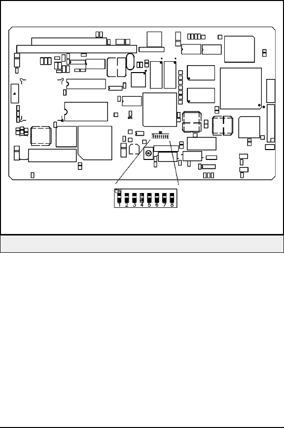
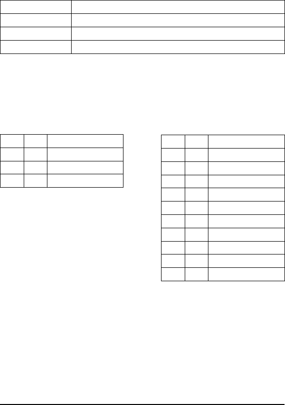
Digital Board DIP Switch
The digital board is mounted inside the top of the LRP830 enclosure. The
first 5 switches of the main board sets the COM1 baud rate, electrical inter-
face, and the download options for COM2. Switches 6, 7 and 8 are not used
and should remain OFF. When switch 1 and 2 are both set ON, the baud
rate is set via the Configuration Menu.
NOTE:
When you set switch 5 ON to enable download, the default parameters will
first be restored and saved to the non-volatile memory.
The baud rate configuration on the main board only applies to the RS232
and RS422 serial interfaces. When a Bus Interface (DeviceNet) is selected,
the baud rate is set by the Interface Board DIP switches.
Copyright © 2000 Escort Memory Systems
30 LRP830-Series Long-Range Passive Reader/Writer
Figure 28 — Digital Board with DIP Switch
NOTE:
DIP switch 4 must be in the default ON position for the DeviceNet interface
to function.
Copyright © 2000 Escort Memory Systems
LRP830-Series Long-Range Passive Reader/Writer 31
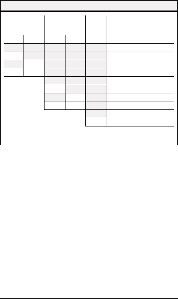
Baud rate Interface
Download/
Restore
Defaults
SW 1 SW 2 SW 3 SW 4 SW 5 Settings
9600
ON 19200
ON 38400
ON ON Set from Configuration Menu
RS232
ON RS422
ON DeviceNet
ON ON Reserved
Disabled
ON Enabled Download/ Restore defaults
Switches 6 through 8 are reserved and must be in the OFF position.
Table 5 Main Board DIP Switch Settings
4.2 Bus Interfaces
The COM1 serial port, beside the RS232 or RS422 options, can be config-
ured as a DeviceNet interface.
The following bus parameters are set by the DIP switches found on the
Interface Board.
DeviceNet interface
nBus Rate: 125K, 250K, 500Kbps
nDeviceNet Node Address (MAC ID)
Copyright © 2000 Escort Memory Systems
32 LRP830-Series Long-Range Passive Reader/Writer
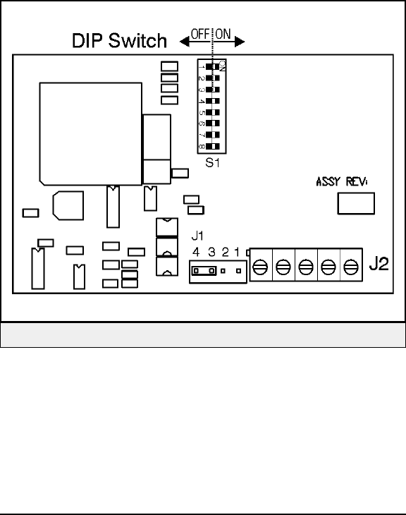
Figure 29 — DeviceNet Interface Board DIP Switch

DeviceNet Interface Board DIP Switch
S1 is an eight position DIP switch. Switches 1 to 6 set the DeviceNet Node
address, switches 6 and 7 are reserved and switch 8 sets the bus rate. Table 6
shows these settings.
Copyright © 2000 Escort Memory Systems
LRP830-Series Long-Range Passive Reader/Writer 33
DeviceNet Node Switches Bus Rate
Settings
SW1 SW2 SW3 SW4 SW5 SW6 SW7 SW8
ON DeviceNet Node 1
ON DeviceNet Node 2
ON ON DeviceNet Node 3
ON DeviceNet Node 4
ON ON DeviceNet Node 5
ON ON DeviceNet Node 6
ON ON ON DeviceNet Node 7
ON DeviceNet Node 8
ON ON DeviceNet Node 9
ON ON DeviceNet Node 10
ON ON ON DeviceNet Node 11
ON ON DeviceNet Node 12
ON ON ON DeviceNet Node 13
ON ON ON DeviceNet Node 14
ON ON ON ON DeviceNet Node 15
ON DeviceNet Node 16
ON ON DeviceNet Node 17
ON ON DeviceNet Node 18
ON ON ON DeviceNet Node 19
ON ON DeviceNet Node 20
ON ON ON DeviceNet Node 21
ON ON ON DeviceNet Node 22
ON ON ON ON DeviceNet Node 23
ON ON DeviceNet Node 24
ON ON ON DeviceNet Node 25
ON ON ON DeviceNet Node 26
ON ON ON ON DeviceNet Node 27
ON ON ON DeviceNet Node 28
ON ON ON ON DeviceNet Node 29
ON ON ON ON DeviceNet Node 30
ON ON ON ON ON DeviceNet Node 31
Table 6 — DeviceNet DIP Switch Settings

Copyright © 2000 Escort Memory Systems
34 LRP830-Series Long-Range Passive Reader/Writer
DeviceNet Node Switches Bus Rate
Settings
SW1 SW2 SW3 SW4 SW5 SW6 SW7 SW8
ON DeviceNet Node 32
ON ON DeviceNet Node 33
ON ON DeviceNet Node 34
ON ON ON DeviceNet Node 35
ON ON DeviceNet Node 36
ON ON ON DeviceNet Node 37
ON ON ON DeviceNet Node 38
ON ON ON ON DeviceNet Node 39
ON ON DeviceNet Node 40
ON ON ON DeviceNet Node 41
ON ON ON DeviceNet Node 42
ON ON ON ON DeviceNet Node 43
ON ON ON DeviceNet Node 44
ON ON ON ON DeviceNet Node 45
ON ON ON ON DeviceNet Node 46
ON ON ON ON ON DeviceNet Node 47
ON ON DeviceNet Node 48
ON ON ON DeviceNet Node 49
ON ON ON DeviceNet Node 50
ON ON ON ON DeviceNet Node 51
ON ON ON DeviceNet Node 52
ON ON ON ON DeviceNet Node 53
ON ON ON ON DeviceNet Node 54
ON ON ON ON ON DeviceNet Node 55
ON ON ON DeviceNet Node 56
ON ON ON ON DeviceNet Node 57
ON ON ON ON DeviceNet Node 58
ON ON ON ON ON DeviceNet Node 59
ON ON ON ON DeviceNet Node 60
ON ON ON ON ON DeviceNet Node 61
ON ON ON ON ON DeviceNet Node 62
ON ON ON ON ON ON DeviceNet Node 63
125k
ON 259k
ON 500k
ON ON Reserved
Table 5 — DeviceNet DIP Switch Settings (cont.)

5 MENU CONFIGURATION
The LRP830 feature a menu-driven program designed to give convenient
access to the serial parameters, restore defaults or change operating modes.
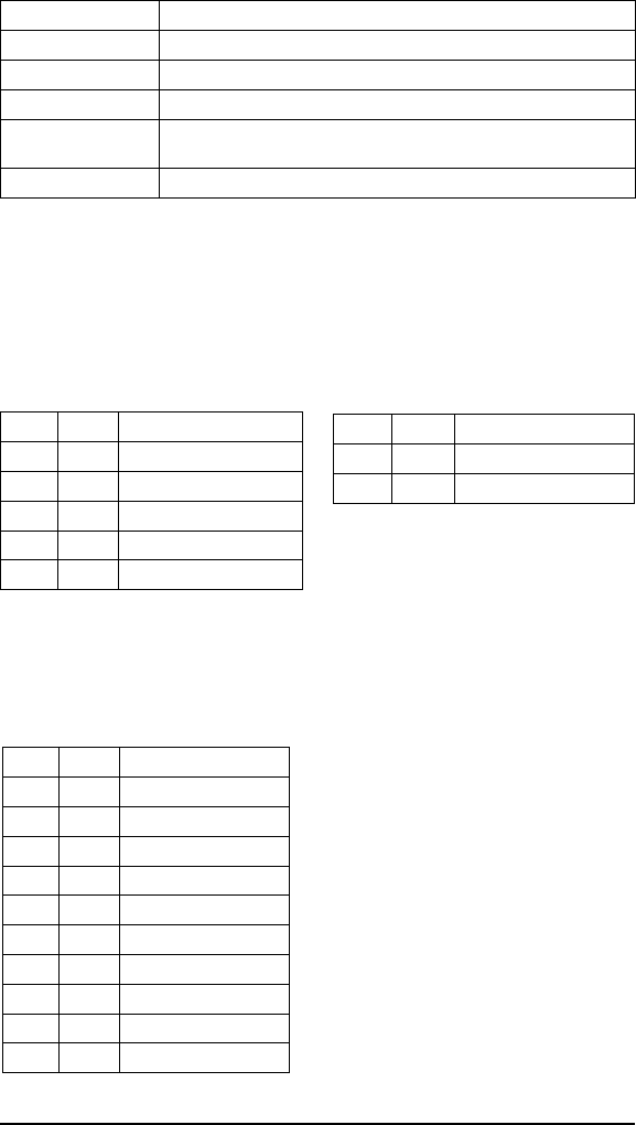
5.1 How to Enter Menu Configuration
Begin by connecting the COM2 port to your PC host (see table below) and
running EC that is available on the diskette or from Escort Memory Sys-
tems’ Web site at www.ems-rfid.com.
LRP830 Standard PC Serial Port
COM2 Pin Number Signal Name DB9 Pin Number Signal Name
RTX2 RX
PRX3TX
M GND 5 GND
Set the serial parameters to the LRP830 default settings or the last known
state of COM2.
The default settings for COM2 are as follows:
Baud 9600
Parity None
Data bits 8
Stop bits 1
Flow control None
If you can not establish communications with COM2, do the following to
restore the default values.
1. Place DIP switch five in the ON position and cycle power to
the LRP830 or press the reset switch. This will load the default
values.
2. Place DIP switch 5 in the OFF position and cycle power once
more.
Please refer to Chapter 4, Serial and Bus Communications for more infor-
mation on the serial interface.
Copyright © 2000 Escort Memory Systems
LRP830-Series Long-Range Passive Reader/Writer 35

To enter the Main Board configuration menu, cycle power or press the reset
switch, and then press CTRL-D within the first seven seconds of the initial-
ization. The LRP830 will enter the Configuration Menu. As the LRP830
starts the Configuration program, both the RF and CONFIG LEDs will
flash. The Main Board Configuration menu will display with the current
software version number together with the DSP firmware version.
******************************************************
LRP830 Standard Program
Software V1.7C, June 2000
DSP Firmware V1.7B, August 2000
*******************************************************
[1] Set-up Operating Parameters
[2] Download New Program
[3] Download DSP Firmware
[4] Exit to Operating Mode
Enter Selection:
5.2 Set-up Operating Parameters
To change the operating parameters of the LRP830, enter 1 at the initial
menu. The following menu will be displayed, listing the current settings:
The exact appearance of the menu display will depend on the settings you
have made, and will be updated when you save your changes.
Serial Port COM1: RS232, 9600, N, 8, 1, No handshake (DIP switches)
Serial Port COM2: RS232, 9600, N, 8, 1, No handshake
Operating Mode: ABx Standard
RF Communication: Fast Mode
[1] Set COM1 Parameters
[2] Set COM2 Parameters
[3] Set Operating Mode
[4] Set RF Communications
[5] Restore Factory Defaults
[6] Return to Main Menu
Enter Selection:
Enter the number of the sub-menu you wish to enter. When you have made
your selection you will be prompted to save your changes to the non-volatile
EEPROM. For the new settings to take effect, you must save your changes
to the EEPROM and reset the LRP830. If you do not save changes to the
EEPROM, the new settings will be effective only until the LRP830 is reset.
Copyright © 2000 Escort Memory Systems
36 LRP830-Series Long-Range Passive Reader/Writer

The following sub-menus are presented here in their entirety. Actually the
menus will presented one option at time, advancing as you enter selections.
Some options shown are dependent on earlier selections.
Set COM1 Parameters
Selecting 1 from the above menu will present the following display for the
COM1 parameters. These settings are valid only if you are not using the
DeviceNet Interfaces (e.g. DIP switch 4 is in the OFF position). Enter the
appropriate number at each prompt. The default values are indicated by an
asterisk (*).
*** Set COM1 Parameters ***
Baud Rate? [0] 1200 [1] 2400 [2] 4800 [3] 9600* [4] 19200 [5] 38400
Data size? [0] 7 bit [1] 8 bit*
Parity? [0] None* [1] Even [2] Odd
Handshake? [0] None* [1] Xon/Xoff
Save Changes to EEPROM? [0] No [1] Yes
Set COM2 Parameters
Selecting 2 from the above menu will bring to the following display for the
COM2 parameters. Enter the appropriate number at each prompt. The
default values are indicated by an asterisk.
*** Set COM2 Parameters ***
Baud Rate? [0] 1200 [1] 2400 [2] 4800 [3] 9600* [4] 19200
Data size? [0] 7 bit [1] 8 bit*
Parity? [0] None* [1] Even [2] Odd
Handshake? [0] None* [1] Xon/Xoff
Save Changes to EEPROM? [0] No [1] Yes
Set Operating Mode
The Set Operating Mode menu allows you to choose the command protocol
the LRP830 will use or configure it to automatically enter Continuous Read
Mode upon start-up.
Copyright © 2000 Escort Memory Systems
LRP830-Series Long-Range Passive Reader/Writer 37

*** Set Operating Mode ***
Command Protocol? [0] ABx Standard* [1] ABx Fast [2] ABx ASCII
Checksum? [0] Disabled* [1] Enabled
Power up in Continuous Read Mode? [0] NO [1] Single Tag [2] Multiple Tag
Start Address (0 to 47)
Length (1 to 48)
Delay Between Duplicate Decodes (0 to 60)
Raw Read Response? [0] NO [1] CR terminate [2] CR/LF terminate
Save Changes to EEPROM? [0] No [1] Yes
Command Protocol?
The LRP830 offers three modes for the transfer of data and commands. ABx
Standard (ABxS) uses only the LSB for tag data while ABx Fast (ABxF)
will use both the MSB and the LSB for the passing of data. ABx ASCII
(ABxA) mode permits RFID operations using seven bit data packets in the
form of printable ASCII characters.
Checksum?
ABx Fast and ABx ASCII also permits you to include a checksum in the
command. To use a checksum value with the ABx commands, you must
enable the checksum option. It is recommended that you enable the
checksum option.
Power up in Continuous Read Mode?
You also have the option of setting the LRP830 to start-up in Continuous
Read Mode. When you have configured the LRP830 to function in this
manner, you do not issue commands to the LRP830. It will, upon start-up,
enter directly into a Continuous Read Mode. Since this bypasses the normal
command parameters, you must specify the Continuous Read Mode
parameters.
The LRP830 will respond to other commands and resume Continuous Read
Mode when completed.
This option will not function over a DeviceNet bus.
If you are using your LRP830 in this mode, you must choose if you want the
LRP830 to read a single tag or read multiple tags within the field.
To exit Continuous Read Mode you must either re-enter the configuration
menu and select NO from the Power up in Continuous Read Mode option,
or issue a Continuous Read command from the host with a read length of 0
as described in Chapter 6, RFID Interface.
Copyright © 2000 Escort Memory Systems
38 LRP830-Series Long-Range Passive Reader/Writer

Start Address (0-47)
Enter the tag address where you want the read to begin.
Length (1-48)
Enter the length of the read you wish the LRP830 to perform. Make certain
that the length value does not exceed the number of possible addresses fol-
lowing the starting tag address. Entering a read length of 0 will disable Con-
tinuous Read Mode.
Delay Between Identical Decodes (0-60)
The Delay Between Identical Decodes parameters can have a value of 0 to
60 seconds. When the Delay Between Identical Decodes is set to 0, the
LRP830 will continuously read AND transmit tag data to the host. This can
flood the buffers and cause communication errors and data loss.
Raw Read Response?
If you have selected ABx Fast or ABx ASCII, you have the option of strip-
ping the command protocol from the data and adding a terminator to sepa-
rate the data packets. You can choose a CR (0DH) or CR/LF (0DH, 0AH) to
terminate the data.
Set RF Communication
The LRP830 should be configured with the default (0) Fast Mode.
*** Set RF Communication ***
RF Communication? [0] Fast Mode* [1] Standard Mode 0
Save Changes to EEPROM? [0] No [1] Yes
Restore Factory Defaults
It is often helpful during troubleshooting to restore the LRP830 to known
default values. To do so, select 1from this menu.
*** Restore Factory Defaults ***
Restore Factory Default? [0] No [1] Yes
The restored defaults will be saved to the EEPROM. The communication
defaults can also be restored by placing the main board DIP switch number 5
in the ON position and then restarting the LRP830. After you have saved
any changes, you must re-initialize the LRP830 with switch 5 in the OFF
position.
Copyright © 2000 Escort Memory Systems
LRP830-Series Long-Range Passive Reader/Writer 39

Return to Main Menu
When you have completed your configuration, entering 5 will return you to
the initial menu. Unsaved changes will be effective until the LRP830 is re-
set. Saved changes will be loaded automatically the next time the LRP830 is
reset.
5.3 Download New Program
Before attempting to download new firmware to the LRP830 main board,
read the instructions provided in a readme.txt file on the update diskette.
When you select 2 from the Main Menu, the LRP830 will display informa-
tion on the current program and prompt you to begin the download.
*** Download New Program***
Program Size :21824 Bytes
Program Checksum :5AE0H (OK)
Free Program Memory :39600 Bytes
Flash Write Counter :2 times
Press a key to start Downloading
After you have pressed a key, the LRP830 will display:
Send the Intel Hex file. Downloading now.
Send the new program file via your terminal emulation program in ASCII
text or Hexadecimal format. Wait 10 seconds after the download is complete
before resetting the LRP830.
IMPORTANT:
It is not necessary to download firmware into the unit unless instructed to do
so by Escort Memory Systems technical support personnel.
5.4 Downloading DSP Firmware
Before attempting to download new firmware to the LRP830 main board,
read the instructions provided in a readme.txt file on the update diskette.
When upgrading software in the controller the number and meaning of the
configuration parameters may not match between the old and new software.
The old settings may not be interpreted properly with the new software. Be-
Copyright © 2000 Escort Memory Systems
40 LRP830-Series Long-Range Passive Reader/Writer

fore downloading another version of software, display and record the current
configuration settings. Then download the new software version. Set switch
5 (on the main board) on and apply power to initialize the configuration pa-
rameters to their default states. When the LEDs stop flashing, turn Switch 5
to Off and press the reset switch. Enter the Configuration Menu and re-enter
any non-default configuration parameters.
When you select 3 from the Main Menu, the LRP830 will prompt you to
begin the download.
*** Download DSP Firmware***
Press a key to start Downloading
After you have pressed a key, the LRP830 will display:
Send the Intel Hex file. Downloading now.
Send the new firmware via your terminal emulation program in ASCII text
or Hexadecimal format. The firmware will be automatically transferred to
the DSP Flash Memory. Wait 10 seconds after the download is complete
before resetting the LRP830.
Record: 750
Download OK
File Transfer to DSP
Blocco 24/24
DSP Flash Programming...
New Firmware Transferred to DSP
WARNING:
Do not download INTERFACE BOARD firmware to the main board.
IMPORTANT:
It is not necessary to download firmware into the unit unless instructed to do
so by Escort Memory Systems technical support personnel.
5.5 Exit to Operating Mode
This option is available if you wish to use temporary, unsaved, configuration
parameters. The unsaved options you have selected will be used until the
LRP830 is reset and the saved parameters are restored.
Copyright © 2000 Escort Memory Systems
LRP830-Series Long-Range Passive Reader/Writer 41

6RFID INTERFACE
6.1 Introduction
The LRP830 offer three possible command protocols: ABx Standard, ABx
Fast and ABx ASCII. The ABx Standard format is word-based and is com-
patible with most existing RFID systems by Escort Memory Systems. The
ABx Fast protocol is a byte-based packet structure that permits command
execution with fewer total bytes transferred. The ABx ASCII protocol is also
a byte-based format that permits the execution of RFID commands using a
seven-bit ASCII character set.
The ABx Fast protocol is the most efficient and therefore recommended by
Escort Memory Systems. Table 7 lists the ABx commands available for the
LRP830.
The LRP830 command set is made of two subsets: the ‘Non-Anticollision’
commands and the ‘Anticollision’ commands. The Anticollision commands
allow you to manage the multiple-tags-in-field capability of the LRP system.
Command Timeout
Most commands have a timeout value that is used to limit the time the
LRP830 will attempt to complete the specified operation. This value is given
in 1 ms increments with a maximum value of 65,534 ms. A timeout value of
0 will generate a syntax error.
Between 500ms and 1000ms is recommended for a timeout value for single
tag commands. Shorter timeouts may result in diminished range. A 30ms
timeout value is the shortest allowable timeout and should only be used for
short range, single tag command applications. Multiple tag commands will
require longer timeout values. For time critical applications the timeout
value should be tested to obtain the maximum performance value. A longer
timeout value does not mean that the command will take any longer to exe-
cute if the tag being addressed is in the field, it only represents the period of
time (in milliseconds) the unit will attempt to execute the command. If the
tag is present, the response time to execute the command will be the same
whether the timeout is 100ms or 10,000ms.
Copyright © 2000 Escort Memory Systems
42 LRP830-Series Long-Range Passive Reader/Writer

NOTE:
The delay between the characters of the command packet the LRP830 can-
not be longer than 200 ms.
Copyright © 2000 Escort Memory Systems
LRP830-Series Long-Range Passive Reader/Writer 43
Non-Anticollision Commands
04 Hex Fill Tag
05 Hex Block Read
06 Hex Block Write
07 Hex Read Tag Serial Number
08 Hex Tag Search
0D Hex Continuous Block Read*
10 Hex Set Output
11 Hex Input Status
Anticollision Commands
84 Hex Fill Tag All*
85 Hex Block Read All*
86 Hex Block Write All*
87 Hex Read Tag Serial All*
88 Hex Tag Search All*
89 Hex EAS Set/Reset
8A Hex EAS Start/Stop
8D Hex Continuous Read All*
8E Hex Memory Lock
94 Hex SN Fill
95 Hex SN Block Read
96 Hex SN Block Write
97 Hex SN Block Read All*
*These commands can not be used with DeviceNet.
Table 7 - ABx Command Set Listing

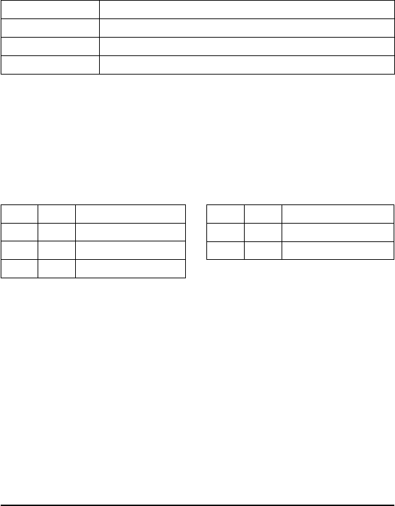
DeviceNet and Anticollision ABx Limitations
The LRP830 does not support the following “All” commands in multiple
tag-in-field mode (i.e. Anticollision Index is not 0) over a DeviceNet
interface:
Command Number Command
84H Fill Tag All
85H Block Read All
86H Block Write All
87H Read Tag SN All
88H Tag Search All
8DH Continuous Read All
97H SN Block Read All
The entire command set is available for point-to-point serial communica-
tions.
Copyright © 2000 Escort Memory Systems
44 LRP830-Series Long-Range Passive Reader/Writer
6.2 ABx Error Codes
Non-Anticollision Error Codes
The LRP830 will return an error if it encounters a fault during operation.
Table 7 lists the possible error codes in Hexadecimal format.
Additionally there are internal DSP errors, F1H through F5H, for use by
Escort Memory Systems technical support.
ABx Standard
ABxS error codes are returned in the LSB of the second register passed to
the PLC. The format of the error response is shown below.
A Block Write fail error message would appear as: AAFF 0006 FFFFH.
Copyright © 2000 Escort Memory Systems
LRP830-Series Long-Range Passive Reader/Writer 45
Error Code Description
04H Fill Operation has failed
05H Block Read has failed
06H Block Write has failed
08H Search Tag Operation failed
21H Input Command does not match pre-defined format (syntax error)
Table 7 — Non-Anticollision Error Codes
MSB LSB Remarks
AAH FFH Command Error
00H XXH Error Code
FFH FFH Message Terminator
ABx Fast
The format of the error response is shown below.
A Block Write fail error message would appear as: 0202 0002 FF06 F803H.
ABx ASCII
The format of the error response is shown below.
In ABx ASCII format the response size is the number of hex values and not
the number of ASCII characters used to represent the hex value.
A Block Write fail error message would appear as an ASCII character
string: <STX><STX>0002FF06F8<ETX>.
In hexadecimal the commands appears as:
02H 02H 30H 30H 30H 32H 46H 46H 30H 36H 46H 38H 03H
Copyright © 2000 Escort Memory Systems
46 LRP830-Series Long-Range Passive Reader/Writer
Field Bytes Contents
Header
<STX><STX>
02H
02H
Response Size 00H
02H
Error Flag FFH
Error Code XXH
Checksum XXH
Terminators <ETX> 03H
Field # of ASCII
characters
Contents
Header
<STX><STX> 2
<STX> 02H
<STX> 02H
Response Size 4 Packet length in bytes excluding the header, response size,
checksum and terminator bytes
Error Flag 2 FFH
Error Code 2 XXH - see Table 7 for details
Checksum 2 XXH - optional checksum
Terminators <ETX> 1 <ETX> 03H

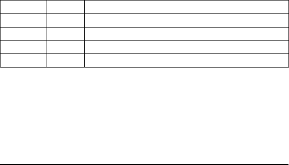
Anticollision Status Byte
When the anticollision commands encounter a fault condition they indicate
the set a bit in a STATUS byte returned in the response. The format of the
response is otherwise the same as a successful response.
The STATUS byte is defined as follows:
76543210
Antenna
Failure
R/W Error Collisions Internal
Error
Timeout Verify
Error
Reserved Reserved
Some of the conditions are the same as found in the non-anticollision com-
mands, other are new and relate only to the anticollision.
If any of the flag bits of the returned Status are set, then that condition
occurred during the command execution. Multiple conditions can occur in
the same command.
Antenna There is an error at the antenna
Failure
R/W error Error during the tag memory access
Collision Collisions detected: more than one tag in the field answered to
the LRP830 at the same time, meaning a higher Anticollision
Index probably needs to be set
Internal Error Internal error in low-level firmware
(contact Escort Memory Systems technical assistance)
Timeout Timeout expired
Verify Error Set when re-read verification fails
Syntax Errors
Syntax errors (error code 21H) will be returned in the same format as
described for the non-anticollision commands.
Copyright © 2000 Escort Memory Systems
LRP830-Series Long-Range Passive Reader/Writer 47

6.3 Anticollision Commands
Family Interrogation
The anticollision commands always have a Family ID and an Anticollision
Index as parameters. These parameters manage the read/writes when multi-
ple tags are in the same reading field. The Family ID and Anticollision Index
can be used separately or together. If the Family ID is zero, that feature is
disabled, if the Anticollision Index is zero, this feature (and multiple
tag-in-field) is disabled as well.
If both the features are disabled, the commands operate exactly the same as
the Non-Anticollision commands.
Family ID
The Family ID is a 1 byte field in the LRP tag memory at address 0. When
the Family ID parameter is set to zero, the command is broadcast to all the
tags in the field. On the other hand, if it is not equal to zero, only the tags
with the specified Family ID in byte 1will respond to the LRP830.
This feature can help in implementing a multi-level organization of the tags,
by permitting the selective reading of tags by Family ID. This gives faster
access to the tags than by using Anticollision Index alone. As previously
noted, Family ID and the Anticollision Index can be used together for
increased efficiency.
When using the Family ID feature, the first byte of tag memory is reserved,
and thus only 47 bytes are allowed to be used. When the feature is disabled,
48 bytes are available for user data.
For this reason, in the read and write commands, once the parameter Family
ID is not equal to zero, the addresses can go from 1 to 47, and the size from
0 to 47. However, when the Family Code is zero, the addresses can start
from 0, and the size can be up to 48.
In order to initialize a tag with a chosen Family ID, byte 0 in the tag must be
set to that value by means of a Block Write or a Block Write All command.
Copyright © 2000 Escort Memory Systems
48 LRP830-Series Long-Range Passive Reader/Writer

Anticollision Index
The Anticollision Index controls the tag reading algorithm to achieve the
fastest reading speed for the number of tags expected in the reading field at
any given moment. It also can disable the multiple tag-in-field feature when
set to 0.
The Anticollision Index should be set in relation to the maximum number of
tags possibly present in the reading field at one time. Setting the
Anticollision Index higher increases the number of tags that will be expected
to be read in the field. Lowering the Index speeds up the tag read operation.
Selecting the Anticollision Index is therefore a tradeoff choice between the
number of tags in the reading field, and the time required to read/write to
them. Regardless of the index setting, ALL tags present will be read. The in-
dex simply makes the process more efficient.
None of the Anticollision Index values will absolutely limit the number
of tags that can be read by the LRP830. The following table can assist you
in setting the Index value, but tests should be done to find the best value.
The allowed values are from 0 to 7.
Anticollision Index Max number of tags
0 1 (*)
1 2-4
2 4-8
3 8-16
4 16-32
5 32-64
6 64-128
7 >128
(*) anticollision disabled
Some commands return or have as a parameter, the Serial Number (SN).
The tag serial number is a unique read-only, 64 bit (8 bytes) code in the tag
memory. SN commands can be used to selectively write to a specific tag,
identified by the SN. A target tag can be identified with a previous SN read
command.
Note that the anticollision commands, except SN Block Write, SN Fill and
Tag Search All, will return a response packet only after the timeout is ex-
pired. If the command has the Anticollision Index set to 0, then a response
will be returned after the first successful operation.
Copyright © 2000 Escort Memory Systems
LRP830-Series Long-Range Passive Reader/Writer 49

The Anticollision Commands return a successful response whenever the op-
eration has successfully been completed on at least 1 tag. They will return an
Error Response when no tag, as permitted by the Family ID and
Anticollision Index, can be found in the antenna field.
Note also that all the start addresses, byte lengths and packet sizes are ex-
pressed in 2 byte words, in order to be compatible with the HMS commands
and to allow future developments.
Copyright © 2000 Escort Memory Systems
50 LRP830-Series Long-Range Passive Reader/Writer

6.3 ABx Standard Protocol
The ABx standard is a binary protocol, word (2-byte) oriented, so the syntax
table reports the Most Significant Byte (MSB) and the Least Significant
Byte (LSB). In the serial transmission, the MSB is transmitted first.
ABxS Command 4 (04H): Fill Tag
DESCRIPTION
Fill an RFID tag with a one byte value over multiple contiguous addresses.
DISCUSSION
This command is commonly used to clear an RFID tag's memory. It writes a
one byte value repetitively across a specified range of tag addresses.
The fill function requires one data value byte, a starting address, and a fill
length. It will then proceed to fill the tag with the data value byte, starting at
the specified start address for the specified number of consecutive bytes.
When Fill Length is set to 0, the LRP830 will write fill data from the start
address to the end of the tag's memory. The timeout value is given in 1 msec
increments and can have a value of 1EH to FFFEH (65,534 ms). When the
timeout is set to 0, the LRP830 will return a syntax error.
Field Remarks
Command Command number in hex preceded by AAH
Start Address The tag address where the fill will start
Fill Length The number of tag addresses to be filled in bytes
Timeout Timeout value given in 1 ms units (1EH - FFFEH)
Data Value Byte The byte to be used as fill
Message Terminator FFFFH
Copyright © 2000 Escort Memory Systems
LRP830-Series Long-Range Passive Reader/Writer 51
6.4 ABx Standard Protocol

EXAMPLE
Writes 'A' (41H) to the tag starting at address 0005H for the following next
consecutive 10 bytes. A timeout of 2 seconds (07D0H = 2000 x 1 msec
increments) is set for the completion of the configuration.
Copyright © 2000 Escort Memory Systems
52 LRP830-Series Long-Range Passive Reader/Writer
Command from Host
MSB LSB Remarks
AAH 04H Perform Command 4
00H 05H Start Address = 0005H
00H 0AH Fill Length= 10 bytes
(0064H)
07H D0H Timeout value
00H 41H Data Value Byte = 41H
FFH FFH Message Terminator
Response from LRP830
MSB LSB Remarks
AAH 04H Command echo
FFH FFH Message Terminator
ABxS Command 5 (05H): Block Read
DESCRIPTION
Read a block of data from an RFID tag.
DISCUSSION
This command is used to read segments of data from contiguous areas of tag
memory. It is capable of handling up to 48 bytes of data transferred to the
host with one command. The timeout value is given in 1 msec increments
and can have a value of 1EH to FFFEH (65,534 ms). When the timeout is
set to 0, the LRP830 will return a syntax error.
The Block Read command consists of a start address and length, followed
by the message terminator, FFFFH, as shown below. If the read range ex-
ceeds the last tag address, the LRP830 will return error message 21H, in-
valid format.
The data read from the tag is returned in the LSB of the register, and the
MSB is always 00H.
Field Remarks
Command Command number in hex preceded by AAH
Start Address The tag address where the read will start
Read Length The number of tag addresses to be read
Timeout Timeout value given in 1 ms units (1EH - FFFEH)
Message Terminator FFFFH
Copyright © 2000 Escort Memory Systems
LRP830-Series Long-Range Passive Reader/Writer 53

EXAMPLE:
Reads 8 bytes of data from the tag starting at address 0001H. A timeout of 2
seconds (07D0H = 2000 x 1 msec increments) is set for the completion of
the Block Read.
Copyright © 2000 Escort Memory Systems
54 LRP830-Series Long-Range Passive Reader/Writer
Command from Host
MSB LSB Remarks
AAH 05H Perform command 5
00H 01H Start Address = 0001H
00H 08H Read Block Length = 8 bytes
(0008H)
07H D0H Timeout Value
FFH FFH Message Terminator
Response from LRP830
MSB LSB Remarks
AAH 05H Command echo
00H 52H Read Data1=52H
00H 46H Read Data2=46H
00H 49H Read Data3=49H
00H 44H Read Data4=44H
00H 20H Read Data5=20H
00H 54H Read Data6=54H
00H 61H Read Data7=61H
00H 67H Read Data8=67H
FFH FFH Message Terminator
ABxS Command 6 (06H): Block Write
DESCRIPTION
Write a block of data to an RFID tag.
DISCUSSION
This command is used to write segments of data to contiguous areas of tag
memory. It is capable of transferring up to 48 bytes of data transferred from
the Host with one command. The timeout value is given in 1 msec incre-
ments and can have a value of 1EH to FFFEH (65,534 ms). When the time-
out is set to 0, the LRP830 will return a syntax error.
The Block Write command consists of a start address followed by the data
stream to be written to the RFID tag. If the write range exceeds the last tag
address, the LRP830 will return error message 21H, invalid format. The
LRP830 will also return an error if the write length is 0.
The data to be written to the tag is contained in the LSB of the register, and
the MSB is always 00H.
Field Remarks
Command Command number in hex preceded by AAH
Start Address The tag address where the write will start
Write Length The number of tag addresses to be written to in bytes
Timeout Timeout value given in 1 ms units (1EH - FFFEH)
Write Data The data to be written
Message Terminator FFFFH
Copyright © 2000 Escort Memory Systems
LRP830-Series Long-Range Passive Reader/Writer 55

EXAMPLE:
Writes 4 bytes of data to the tag starting at address 0020H. A timeout of 2
seconds (07D0H = 2000 x 1 msec increments) is set for the completion of
the Block Write.
Copyright © 2000 Escort Memory Systems
56 LRP830-Series Long-Range Passive Reader/Writer
Command from Host
MSB LSB Remarks
AAH 06H Perform Command 6
00H 20H Start Address = 0020H
00H 04H Write Length = 4 bytes
07H D0H Timeout Value
00H 52H Write Data1=52H
00H 46H Write Data2=46H
00H 49H Write Data3=49H
00H 44H Write Data4=44H
FFH FFH Message Terminator
Response from LRP830
MSB LSB Remarks
AAH 06H Command echo
FFH FFH Message Terminator
ABxS Command 7 (07H): Read Tag Serial Number
DESCRIPTION
Retrieve the eight-byte tag serial number.
DISCUSSION
Each LRP tag has an unique (264 possible numbers) serial number. This
number can not be changed and is not part of the 48 available data bytes. Tag
ID will be return in the LSB only, with the MSB as 00H.
Field Remarks
Command Command number in hex preceded by AAH
Timeout 2-byte timeout value in 1 ms increments (1EH - FFFEH)
Message Terminator FFFFH
EXAMPLE:
This example will wait until a tag is in range and then reads the 8-byte serial
number. In this example the SN is 1E6E3DC200000000H in hexadecimal.
Copyright © 2000 Escort Memory Systems
LRP830-Series Long-Range Passive Reader/Writer 57
Command from Host
MSB LSB Remarks
AAH 07H Perform Command 7
07H D0H Timeout
FFH FFH Message Terminator
Response from LRP830
MSB LSB Remarks
AAH 07H Command Echo
00H 1EH First SN byte
00H 6EH Second SN byte
00H 3DH Third SN byte
00H C2H Fourth SN byte
00H 00H Fifth SN byte
00H 00H Sixth SN byte
00H 00H Seventh SN byte
00H 00H Eighth SN byte
FFH FFH Message Terminator
ABxS Command 8 (08H): Tag Search
DESCRIPTION
Check to see if there is an RFID tag in the LRP830 field.
DISCUSSION
This command will activate LRP830 to "look" for a tag in the RF field. If the
LRP830 finds a tag it will return a command echo to the host. The timeout
value is given in 1 msec increments and can have a value of 1EH to FFFEH
(65,534 ms). When the timeout is set to 0, the LRP830 will return a syntax
error. If no tag is present, it will return an error message. See Section 6.2 for
more information on error codes.
Field Remarks
Command Command number in hex preceded by AAH
Timeout 2-byte timeout value in 1 ms increments (1EH - FFFEH)
Message Terminator FFFFH
EXAMPLE
Checks for an RFID tag in the RF field. A timeout of 2 seconds (07D0H =
2000 x 1 msec increments) is set for the completion of the Tag Search.
Copyright © 2000 Escort Memory Systems
58 LRP830-Series Long-Range Passive Reader/Writer
Command from Host
MSB LSB Remarks
AAH 08H Perform Command 8
07H D0H Timeout Value
FFH FFH Message Terminator
Response from LRP830
MSB LSB Remarks
AAH 08H Command echo
FFH FFH Message Terminator
ABxS Command D (0DH): Continuous Block Read
DESCRIPTION
When in Continuous Block Read mode, the LRP830 sends block reads con-
tinuously to any tag in range of the antenna. When a tag enters the RF field,
it is read and the data passed to the host computer. The LRP830 continues to
read the tag but will not send the same data to the host until the tag has been
outside the RF field for a specified time period. This Delay Between Identi-
cal Decodes feature prevents redundant data transmissions when the
LRP830 is in Continuous Block Read mode.
DISCUSSION
The initiate/cancel Continuous Block Read command contains three param-
eters: read length, start address, and delay between identical decodes. The
read length parameter switches the mode. Any valid, non-zero length (1-48)
will set the LRP830 into Continuous Block Read mode. A read length value
of 00H will turn Continuous Block Mode off.
The Delay Between Identical Decodes value can have a value of 0 to 60
seconds. When the Delay Between Identical Decodes is set to 0, the LRP830
will continuously read AND transmit tag data to the host. This can flood the
buffers and cause communication errors and data loss.
If the LRP830 receives other commands from the host, it will execute them
and then resume Continuous Block Read mode. To exit Continuous Block
Read mode, issue the command with a read length of 0.
In Continuous Block Read mode, the LEDs will display as follows:
LED Behavior Description
ANT LED ON Assumes the Antenna is powered and functioning
CONFIG LED BLINK Tag entered the RF field
RF LED ON A tag has been read and is still in the field
RF LED OFF A read tag has been out of range for the specified time
NOTE:
This command can not be used over a DeviceNet interface.
Copyright © 2000 Escort Memory Systems
LRP830-Series Long-Range Passive Reader/Writer 59
The command is formatted as follows.
Field Remarks
Command Command number in hex preceded by AAH
Start Address 2 byte value for the start address in the tag
Read Length 2 byte value for the block read length
Delay Between
Identical Decodes
Time the tag must be out of the antenna range before the LRP830 will
transmit data again from that tag. Value is expressed in 1 second units.
Message Terminator FFFFH
EXAMPLE
This example places the LRP830 in Continuous Block Read mode and reads
8 bytes of data from the tag starting at address 0001H. A delay between
identical reads of 2 seconds (0002H = 2 x 1 second increments) is set.
The LRP830 will first return an acknowledgment of the command followed
by a response containing read data when a tag enters the antenna field.
Copyright © 2000 Escort Memory Systems
60 LRP830-Series Long-Range Passive Reader/Writer
Command from Host
MSB LSB Remarks
AAH 0DH Perform Command D
00H 01H Start address
00H 08H Read 8 bytes
00H 02H 2 second delay
FFH FFH Message Terminator
Response from LRP830
MSB LSB Remarks
AAH 0DH Command echo
FFH FFH Message Terminator
Response from LRP830
MSB LSB Remarks
AAH 0DH Command echo
00H 52H Read data byte 1
00H 46H Read data byte 2
00H 49H Read data byte 3
00H 44H Read data byte 4
00H 41H Read data byte 5
00H 20H Read data byte 6
00H 54H Read data byte 7
00H 61H Read data byte 8
FFH FFH Message Terminator

To exit Continuous Block Read mode, Send the command with the read
length variable set to 0 as shown below. The value of the other variables are
not considered.
Copyright © 2000 Escort Memory Systems
LRP830-Series Long-Range Passive Reader/Writer 61
Command from Host
MSB LSB Remarks
AAH 0DH Perform Command D
00H 01H Start address
00H 00H Read 0 bytes/end mode
00H 02H 2 second delay
FFH FFH Message Terminator
Response from LRP830
MSB LSB Remarks
AAH 0DH Command echo
FFH FFH Message Terminator
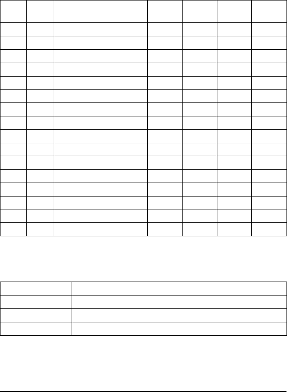
ABxS Command 10 (10H): Set Output
DESCRIPTION
Set the levels of the output lines and output LEDs "A" through "D."
DISCUSSION
This command uses bit logic to set the levels of the digital output lines. The
four least significant bit toggle the output levels;1=ONand0=OFF.The
following chart shows the hex values for all output high combinations. To
reset all output, issue the command with 00H in the second word.
Field Remarks
Command Command number in hex preceded by AAH
Output Pattern Hex value for the bit output settings
Message Terminator FFFFH
Copyright © 2000 Escort Memory Systems
62 LRP830-Series Long-Range Passive Reader/Writer
MSB LSB Remarks LSB Bit 3
Output D
LSB Bit 2
Output C
LSB Bit 1
Output B
LSB Bit 0
Output A
00H 00H Reset A, B, C, D 0000
00H 01H Set Output A - Reset B, C, D 0001
00H 02H Set Output B - Reset A, C, D 0010
00H 03H Set Output A, B - Reset C, D 0011
00H 04H Set Output C - Reset A, B, D 0100
00H 05H Set Output A, C - Reset B, D 0101
00H 06H Set Output B, C - Reset A, D 0110
00H 07H Set Output A, B, C - Reset D 0111
00H 08H Set Output D - Reset A, B, C 1000
00H 09H Set Output A, D - Reset B, C 1001
00H 0AH Set Output B, D - Reset A, C 1010
00H 0BH Set Output A, B, D - Reset C 1011
00H 0CH Set Output C, D - Reset A, B 1100
00H 0DH Set Output A, C, D - Reset B 1101
00H 0EH Set Output B, C, D - Reset A 1110
00H 0FH Set Output A, B, C, D 1111

EXAMPLE
The following example sets Output B only and resets A, C, and D.
Copyright © 2000 Escort Memory Systems
LRP830-Series Long-Range Passive Reader/Writer 63
Command from Host
MSB LSB Remarks
AAH 10H Perform Command 10
00H 02H Set Output B
FFH FFH Message Terminator
Response from LRP830
MSB LSB Remarks
AAH 10H Command echo
FFH FFH Message Terminator
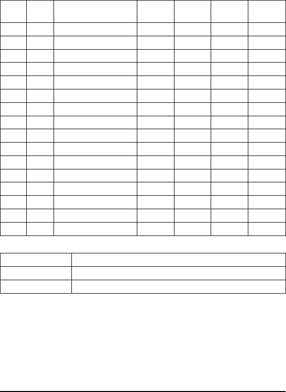
ABxS Command 11 (11H): Input Status
DESCRIPTION
Retrieves the input line levels.
DISCUSSION
This command uses bit logic to monitor the levels of the digital input lines.
The four least significant bit display the output levels;1=ONand0=OFF.
The following chart shows the hex values for all input conditions that can be
returned in word 2 of the response.
Field Remarks
Command Command number in hex preceded by AAH
Message Terminator FFFFH
Copyright © 2000 Escort Memory Systems
64 LRP830-Series Long-Range Passive Reader/Writer
MSB LSB Remarks LSB Bit 3
Input D
LSB Bit 2
Input C
LSB Bit 1
Input B
LSB Bit 0
Input A
00H 00H Inputs A, B, C, D, OFF 0000
00H 01H Input A, ON - B, C, D, OFF 0001
00H 02H Input B, ON - A, C, D, OFF 0010
00H 03H Input A, B, ON - C, D, OFF 0011
00H 04H Input C, ON - A, B, D, OFF 0100
00H 05H Input A, C, ON - B, D, OFF 0101
00H 06H Input B, C, ON - A, D, OFF 0110
00H 07H Input A, B, C, ON - D, OFF 0111
00H 08H Input D, ON - A, B, C, OFF 1000
00H 09H Input A, D, ON - B, C, OFF 1001
00H 0AH Input B, D, ON - A, C, OFF 1010
00H 0BH Input A, B, D, ON - C, OFF 1011
00H 0CH Input C, D, ON - A, B, OFF 1100
00H 0DH Input A, C, D, ON - B, OFF 1101
00H 0EH Input B, C, D, ON - A, OFF 1110
00H 0FH Input A, B, C, D, ON 1111

EXAMPLE
The following example shows only Input B is ON.
Copyright © 2000 Escort Memory Systems
LRP830-Series Long-Range Passive Reader/Writer 65
Command from Host
MSB LSB Remarks
AAH 11H Perform Command 11
FFH FFH Message Terminator
Response from LRP830
MSB LSB Remarks
AAH 11H Command echo
00H 02H Input B ON
FFH FFH Message Terminator
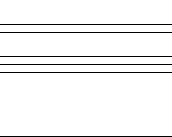
ABxS Command 84 (84H): Fill Tag All
DESCRIPTION
Fill all RFID tags-in-field or all tags in the same family with a one byte
value over multiple contiguous addresses.
DISCUSSION
This command is commonly used to clear an RFID tag's memory. It writes a
one byte value repetitively across a specified range of tag addresses. All tags
present in the antenna field with the specified Family ID will be affected by
this command.
The fill function requires one data value byte, a starting address, and a fill
length. It will then proceed to fill the tag with the data value byte, starting at
the specified start address for the specified number of consecutive bytes.
The Fill Length must be set to a non-zero value (1-48). The timeout value is
given in 1 msec increments and can have a value of 1EH to FFFEH (65,534
ms). When the Anticollision Index is not zero (multiple tag-in-field en-
abled), the LRP830 will return a response after the timeout expires. If the
Anticollision Index is 0, a response is returned when a successful operation
is performed on 1 tag or when the timeout has expired. When the timeout is
set to 0, the LRP830 will return a syntax error.
Field Remarks
Command Command number in hex preceded by AAH
Family Code Tag Family ID - 00H = all tags
Anticollision index Number of tags expected
Start Address The tag address where the fill will start
Fill Length The number of tag addresses to be filled (1-48)
Timeout 2-byte timeout value in 1 ms increments (1EH - FFFEH)
Data Value Byte The byte to be used as fill
Message Terminator FFFFH
NOTE:
This command can not be used over a DeviceNet interface.
Copyright © 2000 Escort Memory Systems
66 LRP830-Series Long-Range Passive Reader/Writer
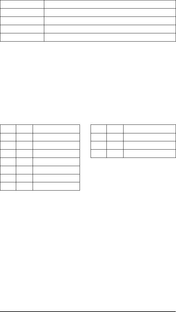
A response to a successful command will follow this form.
Field Remarks
Command Echo Command number in hex preceded by AAH
Number of Tags filled Number of tags found in the field and filled
Command Status One byte Error status
Message Terminator FFFFH
EXAMPLE
Writes 'A' (41H) to all tags of family 01H, starting at tag address 0005H for
the following next consecutive 40 bytes, with four to eight tags expected in
the field. A timeout of 2 seconds (07D0H = 2000 x 1 msec increments) is
set for the completion of the Fill All Tag. The Anticollision Index is set to 2
so 4 to 8 tags will be expected. Four tags are successfully filled within the
timeout.
Copyright © 2000 Escort Memory Systems
LRP830-Series Long-Range Passive Reader/Writer 67
Response from LRP830
MSB LSB Remarks
AAH 84H Command Echo
04H 08H Ntag/Status
FFH FFH Message Terminator
Command from Host
MSB LSB Remarks
AAH 84H Perform Command 84
01H 02H Tag Family 01/ Index 2
00H 05H Start Address
00H 28H Fill Length
07H D0H Timeout
00H 41H Fill byte
FFH FFH Message Terminator

ABxS Command 85 (85H): Block Read All
DESCRIPTION
Read a block of data from all RFID tags-in-field or those with the specified
Family ID.
DISCUSSION
This command is used to read segments of data from contiguous areas of tag
memory. It is capable of handling up to 48 bytes of data transferred to the
host with one command. The timeout value is given in 1 msec increments
and can have a value of 1EH to FFFEH (65,534 ms). When the timeout is
set to 0, the LRP830 will return a syntax error 21H.
The Block Read All consists of Tag Family ID and an Anticollision Index,
a start address and length, followed by a timeout value and the message
terminator. If the read length exceeds the last tag address, the LRP830 will
return a syntax error message 21H.
The data read from the tag is returned in the LSB of the register, and the
MSB is always 00H.
A special termination packet (AAH FFH) is sent after the timeout expires.
When the Anticollision Index is not zero (multiple tag-in-field enabled), the
LRP830 will return a response after the timeout expires. If the Anticollision
Index is 0, the command returns after the successful operation on one tag or
when the timeout expires. No termination packet is sent after a successful
operation when the Anticollision Index set to 0.
Field Remarks
Command Command number in hex preceded by AAH
Tag Family Tag Family ID - 00H = all tags
Anticollision index Number of tags-in-field expected
Start Address The tag address where the read will start
Read Length The number of tag addresses to be read
Timeout 2-byte timeout value in 1 ms increments (1EH - FFFEH)
Message Terminator FFFFH
NOTE:
This command can not be used over a DeviceNet interface.
Copyright © 2000 Escort Memory Systems
68 LRP830-Series Long-Range Passive Reader/Writer
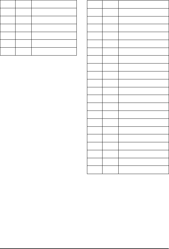
EXAMPLE:
Reads 4 bytes of data from the tag starting at address 0001H. A timeout of 2
seconds (07D0H = 2000 x 1 msec increments) is set for the completion of
the Block Read All. The Family ID byte is set to zero so all tags will be read.
The Anticollision Index is set to 2 so 4 to 8 tags will be expected. Three tags
respond with read data.
Copyright © 2000 Escort Memory Systems
LRP830-Series Long-Range Passive Reader/Writer 69
Command from Host
MSB LSB Remarks
AAH 85H Perform Command 85
00H 02H Tag Family 00/ Index 2
00H 01H Start Address
00H 04H Read Length
07H D0H Timeout
FFH FFH Message Terminator
Response from LRP830
MSB LSB Remarks
AAH 85H Command Echo/Tag 1
00H 30H Data byte 1/Tag 1
00H 31H Data byte 2/Tag 1
00H 32H Data byte 3/Tag 1
00H 33H Data byte 4/Tag 1
FFH FFH Terminator/ Tag 1
AAH 85H Command Echo/Tag 2
00H 40H Data byte 1/Tag 2
00H 41H Data byte 2/Tag 2
00H 42H Data byte 3/Tag 2
00H 43H Data byte 4/Tag 2
FFH FFH Terminator/ Tag 2
AAH 85H Command Echo/Tag 3
00H 34H Data byte 1/Tag 3
00H 35H Data byte 2/Tag 3
00H 36H Data byte 3/Tag 3
00H 37H Data byte 4/Tag 3
FFH FFH Terminator/ Tag 3
AAH FFH Termination Packet
03H 08H Ntag/Status
FFH FFH Terminator Message

ABxS Command 86 (86H): Block Write All
DESCRIPTION
Write a block of data to all RFID tags or all tags with the same Family ID.
DISCUSSION
This command is used to write segments of data to contiguous areas of tag
memory. It is capable of transferring up to 48 bytes of data transferred from
the Host with one command. The timeout value is given in 1 msec incre-
ments and can have a value of 1EH to FFFEH (65,534 ms). When the time-
out is set to 0, the LRP830 will return a syntax error.
The Block Write consists of a Tag Family ID and an Anticollision Index,
start address followed by the data stream to be written to the RFID tag. If the
write range exceeds the last tag address, the LRP830 will return error mes-
sage 21H, invalid format.
The data to be written to the tag is contained in the LSB of the register, and
the MSB is always 00H.
The LRP830 returns a response when the timeout expires. If the
Anticollision Index is 0 the command returns a response after the successful
operation on 1 tag, or when the timeout expires.
Field Remarks
Command Command number in hex preceded by AAH
Family ID Tag Family ID - 0 = all tags
Anticollision Index Number of tags-in-field expected
Start Address The tag address where the write will start
Write Length The number of tag addresses to be written to in bytes
Timeout 2-byte timeout value in 1 ms increments (1EH - FFFEH)
Write Data The data to be written (1-48 bytes)
Message Terminator FFFFH
NOTE:
This command can not be used over a DeviceNet interface.
Copyright © 2000 Escort Memory Systems
70 LRP830-Series Long-Range Passive Reader/Writer
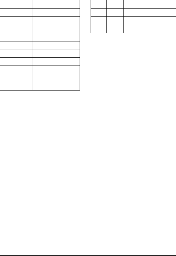
EXAMPLE:
Writes 4 bytes of data, starting at address 0001H. A timeout of 2 seconds
(07D0H = 2000 x 1 msec increments) is set for the completion of the Block
Write. The Family ID byte is set to 2, so all tags with Family ID of 2 will be
written to (four tags in this example). The Anticollision Index is set to 2 so 4
to 8 tags are expected in the field.
Copyright © 2000 Escort Memory Systems
LRP830-Series Long-Range Passive Reader/Writer 71
Command from Host
MSB LSB Remarks
AAH 86H Perform Command 86
02H 02H Tag Family 02/ Index 2
00H 01H Start Address
00H 04H Write Length
07H D0H Timeout
00H 40H Data byte 1
00H 41H Data byte 2
00H 42H Data byte 3
00H 43H Data byte 4
FFH FFH Message Terminator
Response from LRP830
MSB LSB Remarks
AAH 86H Command Echo
04H 08H Ntags/Status
FFH FFH Message Terminator

ABxS Command 87 (87H): Read Tag SN All
DESCRIPTION
This command retrieves the 8-byte tag serial number from all tags or those
with the specified Family ID number.
DISCUSSION
Each LRP tag has an unique (264 possible numbers) serial number. This
number cannot be changed and is not part of the 48 available data bytes. The
Tag SN is returned in the LSB only, with the MSB as 00H.
The timeout value is given in 1 msec increments and can have a value of
1EH to FFFEH (65,534 ms). When the timeout is set to 0, the LRP830 will
return a syntax error. A special termination packet (starting with AAH FFH)
is sent when the timeout expires. If the Anticollision Index is 0, a response
is returned after successful operation to 1 tag or after the timeout has ex-
pired. No termination packet is sent after a successful operation when the
Anticollision Index set to 0.
Field Remarks
Command Command number in hex preceded by AAH
Family ID Tag Family ID - 00H = all tags
Anticollision Index Number of tags-in-field expected
Timeout 2-byte timeout value in 1 ms increments (1EH - FFFEH)
Message Terminator FFFFH
NOTE:
This command can not be used over a DeviceNet interface.
Copyright © 2000 Escort Memory Systems
72 LRP830-Series Long-Range Passive Reader/Writer
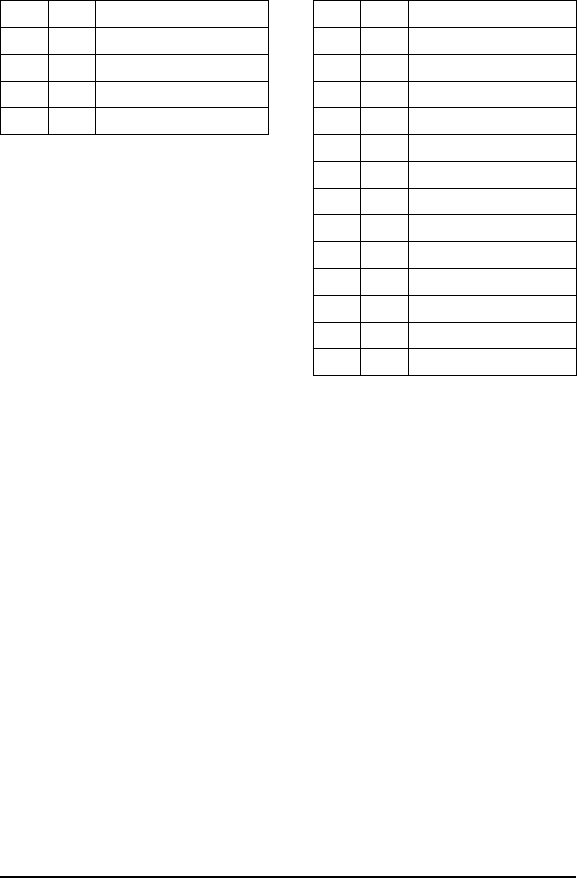
EXAMPLE:
This example will read the 8-byte serial number from Tag Family 2. The
Anticollision Index of 2 sets the number of expected tags at 4-8. In this ex-
ample the SN for the found tag is 1E6E3CD200000000H in hexadecimal.
Multiple tags will return a complete response packet for each tag.
Copyright © 2000 Escort Memory Systems
LRP830-Series Long-Range Passive Reader/Writer 73
Command from Host
MSB LSB Remarks
AAH 87H Perform Command 87
02H 02H Tag Family 02 / Index 2
07H D0H Timeout
FFH FFH Message Terminator
Response from LRP830
MSB LSB Remarks
AAH 87H Command Echo
00H 1EH First SN byte
00H 6EH Second SN byte
00H 3CH Third SN byte
00H D2H Fourth SN byte
00H 00H Fifth SN byte
00H 00H Sixth SN byte
00H 00H Seventh SN byte
00H 00H Eighth SN byte
FFH FFH Message Terminator
AAH FFH Termination Packet
01H 08H Ntags/Status
FFH FFH Message Terminator
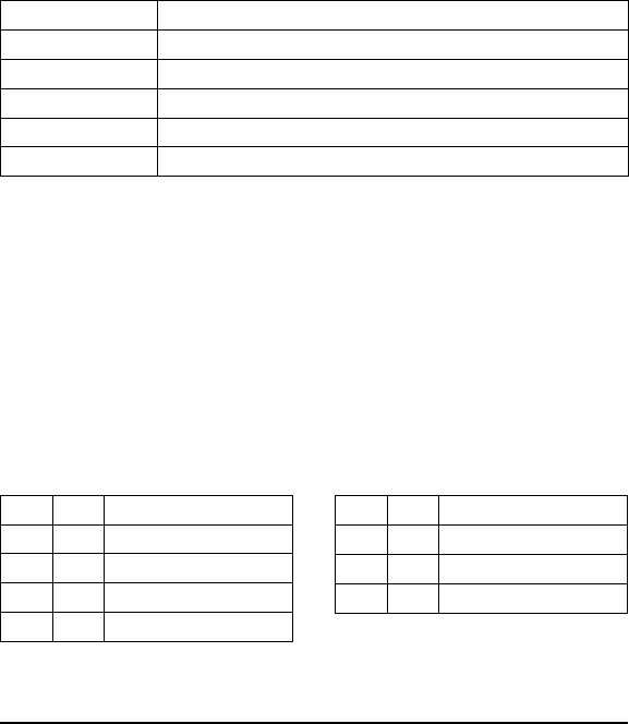
ABxS Command 88 (88H): Tag Search All
DESCRIPTION
Check to see if there is an RFID tag in the LRP830 field.
DISCUSSION
This command will activate LRP830 to "look" for a tag in the RF field. As
soon as the LRP830 finds a tag it will return a command echo to the host.
The timeout value is given in 1 msec increments and can have a value of
1EH to FFFEH (65,534 ms). When the timeout is set to 0, the LRP830 will
return a syntax error. If no tag is present, it will return an error message. See
Section 6.2 for more information on error codes.
The number of tags returned can be either 1 (tag found) or 0 (timeout ex-
pired without having found a tag).
Field Remarks
Command Command number in hex preceded by AAH
Family ID Tag Family ID - 00H = all tags
Anticollision Index Number of tags-in-field expected
Timeout 2-byte timeout value in 1 ms increments (1EH - FFFEH)
Message Terminator FFFFH
NOTE:
This command can not be used over a DeviceNet interface.
EXAMPLE
Checks for an RFID tag in the RF field. A timeout of 1 seconds (07D0H =
2000 x 1 msec increments) is set for the completion of the Tag Search All.
The Family ID is set for any tag, and the Anticollision Index is set to expect
4-8 tags. One tag is found and the command is successful.
Copyright © 2000 Escort Memory Systems
74 LRP830-Series Long-Range Passive Reader/Writer
Command from Host
MSB LSB Remarks
AAH 88H Perform Command 88
01H 01H Family ID / Index 2
07H D0H Timeout
FFH FFH Message Terminator
Response from LRP830
MSB LSB Remarks
AAH 88H Command Echo
01H 00H Ntags/Status
FFH FFH Message Terminator
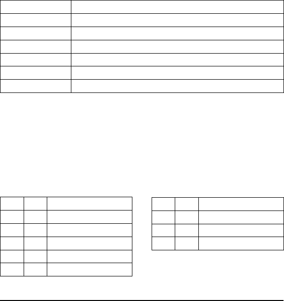
ABxS Command 89 (89H): EAS Set/Reset All
DESCRIPTION
Sets or resets the EAS feature in tag memory for all tags in range, and of the
specified Family, when the command is issued.
DESCRIPTION
The commands contains a 1 byte parameter that enables or disables the EAS
feature in tags that receive the command. When the EAS Set/Reset All com-
mand is issued, the LRP830 responds with the number of tags affected
(Ntag). If the LRP830 returns a 0 for Ntag it means that no tags were set or
reset by the command.
When multiple tag-in-field is enabled (Anticollision Index is not 0), the
LRP830 will return a response when the timeout period expires. When mul-
tiple tag-in-field is disabled, the LRP830 will return a response when it reads
a tag or the timeout expires.
Field Remarks
Command Command number in hex preceded by AAH
Family ID Tag Family ID - 00H = all tags
Anticollision Index Number of tags expected
Timeout 2-byte timeout value in 1 ms increments (1EH - FFFEH)
Set/Reset 1 = Set, 0 = Reset EAS
Message Terminator FFFFH
EXAMPLE
This example assumes that the tags-in-field are not enabled for the EAS
feature. It will enabled the EAS feature for tags with Family ID 09H. The
Anticollision Index is 2, so 4-8 tags are expected in the field. When the com-
mand is issued, 5 tags with Family ID 09H are found and enabled for EAS.
Copyright © 2000 Escort Memory Systems
LRP830-Series Long-Range Passive Reader/Writer 75
Command from Host
MSB LSB Remarks
AAH 89H Perform Command 89
09H 02H Family ID/Anticollision Index 2
07H D0H Timeout
00H 01H Set EAS
FFH FFH Message Terminator
Response from LRP830
MSB LSB Remarks
AAH 89H Command Echo
05H 08H Ntags/Status
FFH FFH Message Terminator
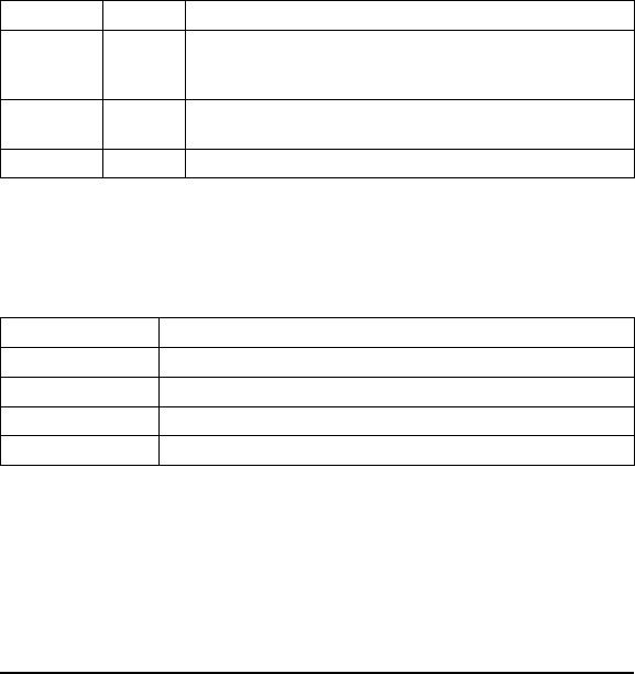
ABxS Command 8A (8AH): EAS Start/Stop
DESCRIPTION
If are using the EAS feature in your application, the EAS Start/Stop com-
mand enters and exits the LRP830 from EAS mode.
DISCUSSION
When EAS mode has been started, the LRP830 will return a response when
one or more EAS-enabled tags have entered the antenna field. It will send a
second response when all EAS-enabled tags have exited the field. The com-
mand contains a control byte that toggles EAS: 1 = start, 0 = stop. A Family
ID can be set so that only EAS-enabled tags from the specified Family trig-
ger EAS responses. The Anticollision Index is ignored and should be set to
00H for this command.
The EAS mode also controls the CONFIG, ERROR and RF LEDs. The
following table:
LED(s) Behavior Description
CONFIG,
ERROR,
RF LEDs
OFF No EAS-enabled tag in field
RF LED ON EAS-enabled tag entered field. LED will remain ON until all EAS tags
have left the field.
ERROR LED BLINKS Last EAS tag left the field.
IMPORTANT:
EAS mode prevents any other commands from being acknowledged or exe-
cuted until EAS has been stopped.
Field Remarks
Command Command number in hex preceded by AAH
Family ID Tag Family ID - 00H = all tags
Start/Stop 1 = start, 0 = stop
Message Terminator FFFFH
Copyright © 2000 Escort Memory Systems
76 LRP830-Series Long-Range Passive Reader/Writer
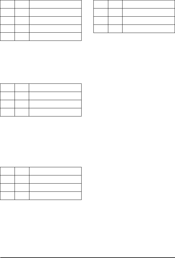
EXAMPLE
This example starts EAS mode. Three responses follow. The first is a com-
mand acknowledgment. The LRP830 sends the second when the first
EAS-enabled tag enters the field, A third response is sent when field is clear
of EAS-enabled tags. Family ID is set to 0 so that any EAS-enabled tag will
trigger responses.
When an EAS-enabled tag enters the antennas’ field, the LRP830 responds
with an EAS tag-in-field response.
When all EAS-enabled tags have left the field, the LRP830 will send the fol-
lowing response.
Copyright © 2000 Escort Memory Systems
LRP830-Series Long-Range Passive Reader/Writer 77
Command from Host
MSB LSB Remarks
AAH 89H Perform Command 89
00H 00H Family ID/null byte
00H 01H Start/Stop
FFH FFH Message Terminator
ACT Response from LRP830
MSB LSB Remarks
AAH 89H Command Echo
FFH 00H Ntag/Status
FFH FFH Message Terminator
Tags-in-Field Response from LRP830
MSB LSB Remarks
AAH 89H Command Echo
01H 00H Ntag/Status
FFH FFH Message Terminator
EAS Tags Left Field
Response from LRP830
MSB LSB Remarks
AAH 89H Command Echo
00H 00H Ntag/Status
FFH FFH Message Terminator
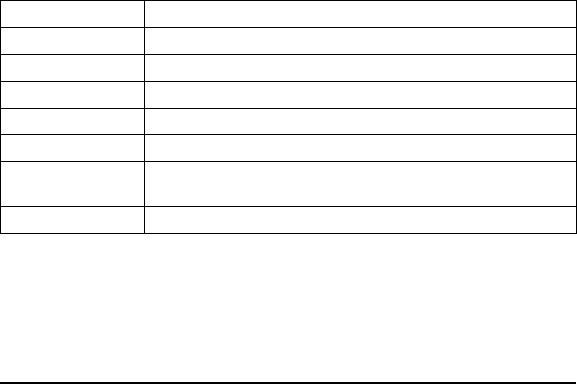
ABxS Command 8D (8DH): Continuous Read All
DESCRIPTION
Starts and stops Continuous Read All mode for multiple tags.
DISCUSSION
Continuous Read All mode is set by the length byte. To start Continuous
Read All mode, send the command with valid, non-zero value for the length
of the read (1-48). Stop the mode by sending the command with a read
length of 0.
While in this mode, any other command can be issued and it will be handled
properly. After processing the new command, the LRP will resume the Con-
tinuous Read All mode.
The command has a parameter, tag delay, that can prevent multiple reads of
the same tag. A tag is not read a second time until a specified number of
tags have been read since it was last read. Allowed value are from 0 to 255
(FFH), where 0 means the tag can be re-read anytime. When Continuous
Read All mode is interrupted with other commands, the tag delay count is
stopped during execution of the other commands and then resumed.
The LRP830 will respond with an acknowledge packet followed by data
packets for each tag read.
CONFIG LED blinks after each packet transmission.
Field Remarks
Command Command number in hex preceded by AAH
Family ID Tag Family ID - 00H = all tags
Anticollision Index Number of tags expected
Start Address Tag address for the start of the read
Read Length 1-48 = start, 0 = stop
Tag Delay Number of tags that must be read before the same tag will be read again
(0-225)
Message Terminator FFFFH
NOTE:
This command can not be used over a DeviceNet interface.
Copyright © 2000 Escort Memory Systems
78 LRP830-Series Long-Range Passive Reader/Writer
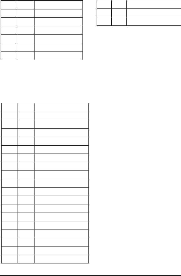
EXAMPLE
Reads 4 bytes of data from the tag starting at address 0001H. The Family ID
byte is set to zero so all tags will be read. The Anticollision Index is set to 2
so 4 to 8 tags will be expected. The Tag Delay is set to 20 (14H). Three tags
respond with read data.
After the LRP830 sends the acknowledgment, it will send the read data from
the 3 tags.
Copyright © 2000 Escort Memory Systems
LRP830-Series Long-Range Passive Reader/Writer 79
Command from Host
MSB LSB Remarks
AAH 8DH Perform Command 8D
00H 02H Tag Family 00/ Index 2
00H 01H Start Address
00H 04H Read Length
00H 14H Tag Delay
FFH FFH Message Terminator
ACK Response from LRP830
MSB LSB Remarks
AAH 8DH Command Echo
FFH FFH Message Terminator
Data response from LRP830
MSB LSB Remarks
AAH 8DH Command Echo/Tag 1
00H 30H Data byte 1/Tag 1
00H 31H Data byte 2/Tag 1
00H 32H Data byte 3/Tag 1
00H 33H Data byte 4/Tag 1
FFH FFH Terminator/ Tag 1
AAH 8DH Command Echo/Tag 2
00H 40H Data byte 1/Tag 2
00H 41H Data byte 2/Tag 2
00H 42H Data byte 3/Tag 2
00H 43H Data byte 4/Tag 2
FFH FFH Terminator/ Tag 2
AAH 8DH Command Echo/Tag 3
00H 34H Data byte 1/Tag 3
00H 35H Data byte 2/Tag 3
00H 36H Data byte 3/Tag 3
00H 37H Data byte 4/Tag 3
FFH FFH Terminator/ Tag 3

ABxS Command 8E (8EH): Memory Lock All
DESCRIPTION
This command “locks” tag addresses in four byte blocks. Once bytes are
locked, they can not be unlocked.
DISCUSSION
The memory can be locked only in 4-byte blocks. The command passes a
two byte word with bits assigned to 4-byte blocks that can be locked. Re-
maining bits can lock the EAS feature and the lock configuration itself.
When multiple tag-in-field is enabled (Anticollision Index is not 0), the
LRP830 will return a response when the timeout period expires. When mul-
tiple tag-in-field is disabled, the LRP830 will return a response when it locks
bytes or the timeout expires.
Attempting to write to locked bytes will return a write error timeout in the
status byte. If you write to addresses that\ contain both locked and
non-locked bytes, the LRP830 will return a write error in the status byte.
The configuration word formatted as shown below.
Byte Bit Description
Lock LSB 0 Tag bytes 0-3
1 Tag bytes 4-7
2 Tag bytes 8-11
3 Tag bytes 12-15
4 Tag bytes 16-19
5 Tag bytes 20-23
6 Tag bytes 24-27
7 Tag bytes 28-31
Lock MSB 8 Tag bytes 32-35
9 Tag bytes 36-39
10 Tag bytes 40-43
11 Tag bytes 44-47
12 Lock Configuration
13 Lock EAS feature
14 Reserved
15 Reserved
Copyright © 2000 Escort Memory Systems
80 LRP830-Series Long-Range Passive Reader/Writer
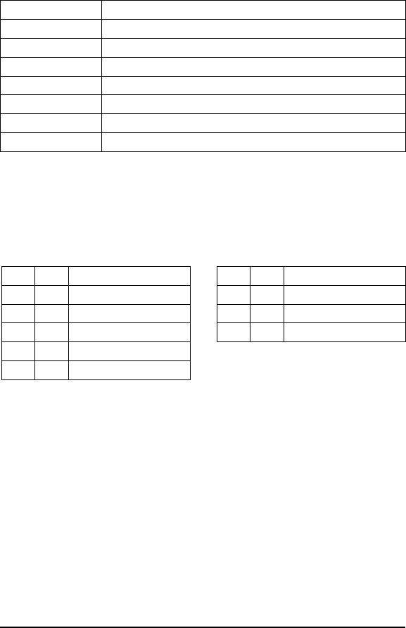
If a bit in the configuration word is set, then the corresponding block in the
tag is locked when the command is issued. If a bit in the configuration word
is cleared (0), then the corresponding block will not change. Once locked, a
block can not be unlocked.
The command is formatted as shown below.
Field Remarks
Command Command number in hex preceded by AAH
Family Code Tag Family ID - 00H = all tags
Anticollision index Number of tags-in-field expected
Timeout 2-byte timeout value in 1 ms increments (1EH - FFFEH)
Lock MSB Bits 8-15 of the configuration word
Lock LSB Bits 0-7 of the configuration word
Message Terminator FFFFH
EXAMPLE
This example will lock bytes 0-3 on all tags-in-field with the Family ID of
02H. Two tags are found and locked.
Copyright © 2000 Escort Memory Systems
LRP830-Series Long-Range Passive Reader/Writer 81
Command from Host
MSB LSB Remarks
AAH 8EH Perform Command 8E
02H 01H Family ID/anticollision Index
07H D0H 2 second timeout
00H 01H Lock Configuration
FFH FFH Message Terminator
Response from LRP830
MSB LSB Remarks
AAH 8EH Command Echo
02H 08H Ntag/Status
FFH FFH Message Terminator
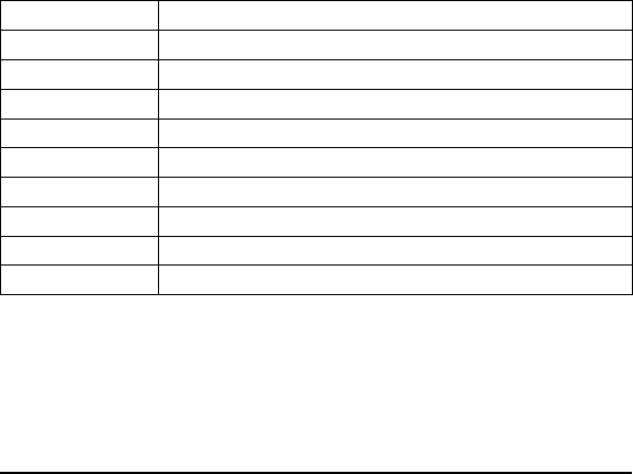
ABxS Command 94 (94H): SN Fill
DESCRIPTION
Fills only the RFID tag specified by serial number with a one byte value
over multiple contiguous addresses.
DISCUSSION
This command is commonly used to clear an RFID tag's memory. It writes a
one byte value repetitively across a specified range of tag addresses. Only
the tag with the specified serial number will be affected by this command.
The LRP830 will return a response after the successful fill operation or
when the timeout expires.
The fill function requires a Family ID and an Anticollision Index, one data
value byte, a starting address, and a fill length. Then the command lists the
serial numbers of the tag to be filled. It fills the specified tag with the data
value byte, starting at the specified start address for the specified number of
consecutive bytes. When Fill Length is set to 0, the LRP830 will write fill
data from the start address to the end of the tags memory.
The timeout value is given in 1 msec increments and can have a value of
1EH to FFFEH (65,534 ms). When the timeout is set to 0, the LRP830 will
return a syntax error. It returns a response when done or when the timeout
expires.
Field Remarks
Command Command number in hex preceded by AAH
Family Code Tag Family ID - 00H = all tags
Anticollision index Number of tags-in-field expected
Start Address The tag address where the fill will start
Fill Length The number of tag addresses to be filled
Timeout 2-byte timeout value in 1 ms increments (1EH - FFFEH)
Tag Serial Number The 8-byte serial number
Data Value Byte The byte used to fill
Message Terminator FFFFH
Copyright © 2000 Escort Memory Systems
82 LRP830-Series Long-Range Passive Reader/Writer
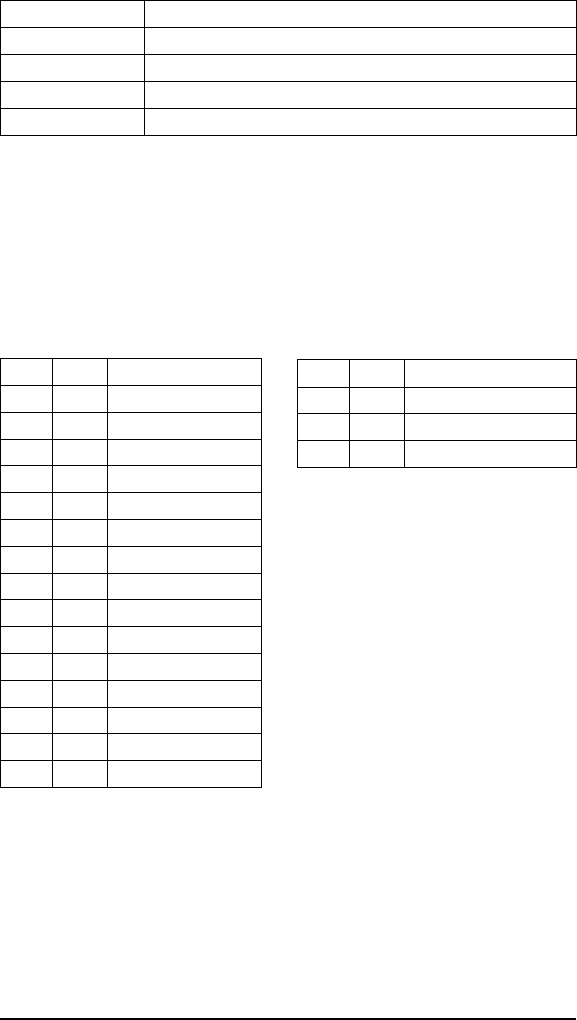
A response to a successful command will follow this form.
Field Remarks
Command Echo Command number in hex preceded by AAH
Number of Tags filled 0 = tag not found, 1 = tag filled
Command Status One byte Error status
Message Terminator FFFFH
EXAMPLE
Writes 'A' (41H) to a single tag, starting at tag address 0005H for the follow-
ing next consecutive 40 bytes. The Family ID is turned off and the
Anticollision Index is set to expect 2-4 tags. A timeout of 2 seconds (07D0H
= 2000 x 1 msec increments) is set for the completion of the configuration.
Copyright © 2000 Escort Memory Systems
LRP830-Series Long-Range Passive Reader/Writer 83
Command from Host
MSB LSB Remarks
AAH 94H Perform Command 94
00H 01H Family ID/ Index 1
00H 05H Start Address
00H 28H Fill Length
07H D0H Timeout
00H 01H SN byte 1
00H ACH SN byte 2
00H 42H SN byte 3
00H D0H SN byte 4
00H 27H SN byte 5
00H 1CH SN byte 6
00H 65H SN byte 7
00H 33H SN byte 8
00H 41H Fill byte
FFH FFH Message Terminator
Response from Host
MSB LSB Remarks
AAH 94H Command Echo
01H 00H Ntag/Status
FFH FFH Message Terminator
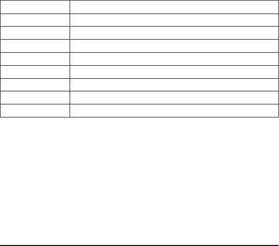
ABxS Command 95 (95H): SN Block Read
DESCRIPTION
Read a block of data from a specified RFID tag.
DISCUSSION
This command is used to read segments of data from contiguous areas of tag
memory. It is capable of handling up to 48 bytes of data transferred to the
host with one command if there is no tag Family ID. The timeout value is
given in 1 msec increments and can have a value of 1EH to FFFEH (65,534
ms). When the timeout is set to 0, the LRP830 will return a syntax error.
The SN Block Read consists of Family ID and an Anticollision Index, a start
address and length, followed by a timeout value. The 8-byte serial number of
the target tag is specified. If the read length exceeds the last tag address, the
LRP830 will return error message in the status byte. It returns a response
when done or when the timeout expires.
The data read from the tag is returned in the LSB of the register, and the
MSB is always 00H. A special error packet (AAH FFH) is sent if the time-
out expires.
Field Remarks
Command Command number in hex preceded by AAH
Tag Family Tag Family ID - 00H = all tags
Anticollision index Number of tags expected
Start Address The tag address where the read will start
Read Length The numbers of tag addresses to be read
Timeout 2-byte timeout value in 1 ms increments (1EH - FFFEH)
Tag Serial Number 8-byte tag serial number
Message Terminator FFFFH
Copyright © 2000 Escort Memory Systems
84 LRP830-Series Long-Range Passive Reader/Writer
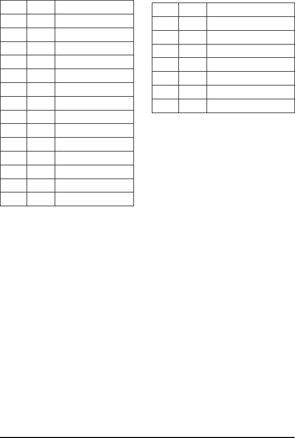
EXAMPLE:
Reads 4 bytes of data from the tag specified by serial number starting at
address 0001H. A timeout of 2 seconds (07D0H = 2000 x 1 msec incre-
ments) is set for the completion of the SN Block Read. The Family ID byte
is set to zero. The Anticollision Index is set to 2, expecting 4-8 tags in the
field.
Copyright © 2000 Escort Memory Systems
LRP830-Series Long-Range Passive Reader/Writer 85
Command from Host
MSB LSB Remarks
AAH 95H Perform Command 95
00H 02H Tag Family 00/ Index 2
00H 01H Start Address
00H 04H Read Length
07H D0H Timeout
00H ABH SN byte 1
00H 02H SN byte 2
00H F3H SN byte 3
00H 55H SN byte 4
00H C5H SN byte 5
00H 2DH SN byte 6
00H 41H SN byte 7
00H A0H SN byte 8
FFH FFH Message Terminator
Response from LRP830
MSB LSB Remarks
AAH 95H Command Echo
00H 30H Data byte 1
00H 31H Data byte 2
00H 32H Data byte 3
00H 33H Data byte 4
01H 00H Ntag/Status
FFH FFH Message Terminator
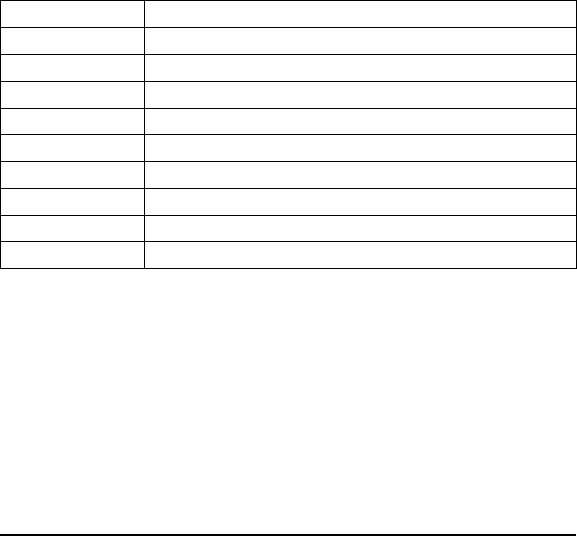
ABxS Command 96 (96H): SN Block Write
DESCRIPTION
Write a block of data to a single RFID tag specified by its serial number.
DISCUSSION
This command is used to write segments of data to contiguous areas of tag
memory. It is capable of transferring up to 48 bytes of data transferred from
the Host with one command. The timeout value is given in 1 msec incre-
ments and can have a value of 1EH to FFFEH (65,534 ms). When the time-
out is set to 0, the LRP830 will return a syntax error.
The SN Block Write consists of a Family ID, Anticollision Index, and start
address followed by the data stream to be written to the RFID tag. If the
write range exceeds the last tag address, the LRP830 will return an error
message 21H, invalid format. It returns a response when done or when the
timeout expires.
The data to be written to the tag is contained in the LSB of the register, and
the MSB is always 00H.
Field Remarks
Command Command number in hex preceded by AAH
Family ID Tag Family ID - 00H = all tags
Anticollision Index Number of tags-in-field expected
Start Address The tag address where the write will start
Write Length The number of tag addresses to be written to
Timeout 2-byte timeout value in 1 ms increments (1EH - FFFEH)
Tag Serial Number 8-byte tag serial number
Write Data The data to be written (1-48 bytes)
Message Terminator FFFFH
Copyright © 2000 Escort Memory Systems
86 LRP830-Series Long-Range Passive Reader/Writer
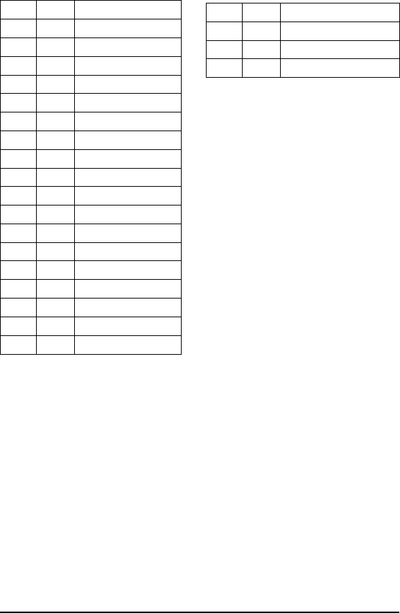
EXAMPLE:
Writes 4 bytes of data, starting at address 0001H. A timeout of 2 seconds
(07D0H = 2000 x 1 msec increments) is set for the completion of the Block
Write. The Family ID byte is set to 0 and the Anticollision Index is set to 2
for this example.
Copyright © 2000 Escort Memory Systems
LRP830-Series Long-Range Passive Reader/Writer 87
Response from LRP830
MSB LSB Remarks
AAH 96H Command Echo
01H 00H Ntags/Status
FFH FFH Message Terminator
Command from Host
MSB LSB Remarks
AAH 96H Perform Command 96
02H 02H Tag Family 02/ Index 2
00H 01H Start Address
00H 04H Write Length
07H D0H Timeout
00H A4H SN byte 1
00H 6CH SN byte 2
00H 18H SN byte 3
00H 92H SN byte 4
00H 2DH SN byte 5
00H 34H SN byte 6
00H DEH SN byte 7
00H 20H SN byte 8
00H 40H Data byte 1
00H 41H Data byte 2
00H 42H Data byte 3
00H 43H Data byte 4
FFH FFH Message Terminator

ABxS Command 97 (97H): SN Block Read All
DESCRIPTION
Read a block of data from all RFID tags-in-field or those with the specified
Family ID. Return the serial number of the tags read, along with tag data.
DISCUSSION
This command is used to read segments of data from contiguous areas of tag
memory. It is capable of handling up to 48 bytes of data transferred to the
host with one command if there is no tag family ID. The timeout value is
given in 1 msec increments and can have a value of 1EH to FFFEH (65,534
ms). When the timeout is set to 0, the LRP830 will return a syntax error.
The response to this command will contain the serial number of the respond-
ing tags preceding the data from those tags. The termination packet is trans-
mitted when the timeout expires. Each packet will be sent to the host as soon
as it is available. The returned serial numbers can be used to read/write to
tags-in-field via the SN Block Read/Write command.
The SN Block Read All consists of Family ID, Anticollision Index, a start
address and length, followed by a timeout value and the message terminator
FFFFH. A special termination packet is sent when the timeout expires. If the
Anticollision Index is 0, a response is returned when the operation is suc-
cessfully completed on 1 tag, or when the timeout expires. A termination
packet is not sent for successful completion if the Anticollision Index is 0.
If the read length exceeds the last tag address, the LRP830 will return an
invalid format error message (error code 21H).
Field Remarks
Command Command number in hex preceded by AAH
Tag Family Tag Family ID - 00H = all tags
Anticollision index Number of tags expected
Start Address The tag address where the read will start
Read Length The number of tag addresses to be read
Timeout 2-byte timeout value in 1 ms increments (1EH - FFFEH)
Message Terminator FFFFH
NOTE:
This command can not be used over a DeviceNet interface.
Copyright © 2000 Escort Memory Systems
88 LRP830-Series Long-Range Passive Reader/Writer

EXAMPLE:
Reads 2 bytes of data from the tag starting at address 0001H. A timeout of 2
seconds (07D0H = 2000 x 1 msec increments) is set for the completion of
the SN Block Read All. The Family ID byte is set to zero so all tags will be
read. The Anticollision Index is set to 2 so 4-8 tags are expected. Two tags
respond with read data.
Copyright © 2000 Escort Memory Systems
LRP830-Series Long-Range Passive Reader/Writer 89
Command from Host
MSB LSB Remarks
AAH 97H Perform Command 97
00H 02H Tag Family 00/ Index 2
00H 01H Start Address
00H 02H Read Length
07H D0H Timeout
FFH FFH Message Terminator
Response from LRP830
MSB LSB Remarks
AAH 97H Command Echo/Tag 1
00H 10H SN byte 1/Tag 1
00H 43H SN byte 2/Tag 1
00H 6CH SN byte 3/Tag 1
00H 73H SN byte 4/Tag 1
00H 92H SN byte 5/Tag 1
00H C0H SN byte 6/Tag 1
00H D6H SN byte 7/Tag 1
00H 54H SN byte 8/Tag 1
00H 30H Data byte 1/Tag 1
00H 31H Data byte 2/Tag 1
FFH FFH Terminator/ Tag 1
AAH 97H Command Echo/Tag 2
00H 08H SN byte 1/Tag 2
00H 0AH SN byte 2/Tag 2
00H 81H SN byte 3/Tag 2
00H 18H SN byte 4/Tag 2
00H 23H SN byte 5/Tag 2
00H CCH SN byte 6/Tag 2
00H D0H SN byte 7/Tag 2
00H EFH SN byte 8/Tag 2
00H 40H Data byte 1/Tag 2
00H 41H Data byte 2/Tag 2
FFH FFH Terminator/ Tag 2
AAH FFH Command Echo/end
02H 08H Ntags/Status
FFH FFH Message Terminator
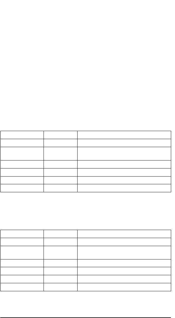
6.4 ABx Fast Protocol
The difference from the standard ABx are:
nThe command/response packet contains the packet size
nYou can include a checksum in the command
nThe headers and terminator are ASCII characters
nSince ABx Fast is a binary protocol, the Xon/Xoff handshake
cannot be used.
ABx Command Packet Structure:
The command protocol is based on the following minimal packet structure.
The data field and the checksum may not be present depending on the com-
mand type and your checksum setting.
Field Number of Bytes Content
Header 2 <STX><STX> (02H, 02H)
Command Size 2 Packet length in bytes excluding the header, command
size, checksum and terminator bytes.
Command 1 Command Code
(Data) variable command data/parameters
(Checksum) 1 Optional Checksum
Terminator 1 <ETX> (03H)
Following a successful operation, the LRP830 will respond with the follow-
ing. The data field and the checksum may not be present depending on your
checksum setting.
Field Number of Bytes Content
Header 2 <STX><STX> (02H, 02H)
Response Size 2 Packet length in bytes excluding the header, response
size, checksum and terminator bytes.
Command 1 Command Echo
(Data) variable response data
(Checksum) 1 Optional Checksum
Terminator 1 <ETX> (03H)
Copyright © 2000 Escort Memory Systems
90 LRP830-Series Long-Range Passive Reader/Writer
6.5 ABx Fast Protocol

If the LRP830 Reader/Writer encounters a fault it will respond with the fol-
lowing:
Field Number of Bytes Content
Header 2 <STX><STX> (02H, 02H)
Response Size 2 Packet length in bytes excluding the header, packet
size, checksum and terminator bytes. (02H in this case)
Error Flag 1 FFH
Error Code 1 Hex error code, see Table 7 for details
(Checksum) 1 Optional Checksum
Terminator 1 <ETX> (03H)
nThe Header and Terminator are always STX-STX and ETX
respectively.
nAll other bytes are interpreted as binary data (0 - 255 dec).
nFields with two bytes are sent most significant byte (MSB)
first.
The sequence for each command is given with the response format in the
following section.
Command/Response Size
The ABx Fast requires that the length of the packet be included in the com-
mand. All parameters and data between the Command/Response Size and
the Checksum or Terminator bytes must be accounted for in the com-
mand/response size word. This includes all command codes and parameters
such as field definitions for Block Read/Writes. The command/response size
will be the same with, or without, a checksum.
Copyright © 2000 Escort Memory Systems
LRP830-Series Long-Range Passive Reader/Writer 91
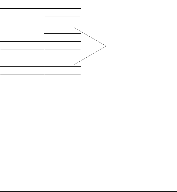
Checksum
Since the DeviceNet protocol has its own data validation, it is not necessary
to use the checksum option when sending ABxF commands over the
DeviceNet bus.
The optional checksum must be enabled from the operating mode menu to
be available. The checksum is calculated by adding all the byte values in the
packet (less the values in the header, checksum if present, and terminator),
discarding byte overflow and subtracting the byte sum from FFH. Thus,
when the packet length through the checksum are added as byte values, the
sum will be FFH.
EXAMPLE
The following is a typical command using a checksum.
The summed values begin with the Command Size and end with the timeout
value. That sum, less overflow, is subtracted from FFH for the checksum
value.
Thus: 00 + 03 + 01 +07 + D0 = DB FF - DB = 24H
The optional Checksum is included in the following command explanations.
Copyright © 2000 Escort Memory Systems
92 LRP830-Series Long-Range Passive Reader/Writer
Command from Host
Field Contents
Header
<STX><STX>
02H
02H
Command Size 00H
03H
Command Code 01H
Timeout 07H
D0H
Checksum 24H
Terminators <ETX> 03H
Sum these values to calculate
the checksum

ABxF Command 4 (04H): Fill Tag
DESCRIPTION
Fill an RFID tag with a one byte value over multiple contiguous addresses.
DISCUSSION
This command is commonly used to clear an RFID tag's memory. It writes a
one byte value repetitively across a specified range of tag addresses.
The fill function requires one data value byte, a starting address, and a fill
length. It will fill the tag with the data value byte, starting at the specified
start address for the specified number of consecutive bytes. When Fill
Length is set to 0, the LRP830 will write fill data from the start address to
the end of the tag’s memory. The timeout value is given in 1 msec incre-
ments and can have a value of 1EH to FFFEH (65,534 ms). When the time-
out is set to 0, the LRP830 will return a syntax error.
Field Content
Header <STX><STX>
Command Size Packet length in bytes excluding the header, command size, checksum and
terminator bytes. 0008H for this command
Command 04H
Start Address 2-byte value for the starting tag address
Fill Length 2-byte value for the length of the fill in number of bytes
Timeout 2-byte timeout value in 1 ms increments (1EH - FFFEH).
Data value byte 1 byte of fill
Checksum Optional Checksum
Terminator <ETX>
A response to a successful command will follow this form.
Field Content
Header <STX><STX>
Command Size Packet length in bytes excluding the header, command size, checksum and
terminator bytes. 0001H for this command
Command 04H
Checksum Optional Checksum
Terminator <ETX>
Copyright © 2000 Escort Memory Systems
LRP830-Series Long-Range Passive Reader/Writer 93
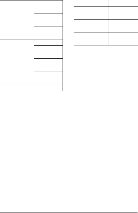
EXAMPLE
Writes 'A' (41H) to the tag starting at address 0005H for the following next
consecutive 40 bytes. A timeout of 2 seconds (07D0H = 2000 x 1 msec in-
crements) is set for the completion of the configuration.
Copyright © 2000 Escort Memory Systems
94 LRP830-Series Long-Range Passive Reader/Writer
Command from Host
Field Bytes Contents
Header
<STX><STX>
02H
02H
Command Size 00H
08H
Command Code 04H
Start address 00H
05H
Block Size 00H
28H
Timeout,
2 seconds
07H
D0H
Data Value Byte 41H
Terminators <ETX> 03H
Response from LRP830
Field Bytes Contents
Header
<STX><STX>
02H
02H
Response Size 00H
01H
Command Echo 04H
Terminators <ETX> 03H

ABxF Command 5 (05H): Block Read
DESCRIPTION
Read a block of data from an RFID tag.
DISCUSSION
This command is used to read segments of data from contiguous areas of tag
memory. It is capable of handling up to 48 bytes of data transferred to the
host. The timeout value is given in 1 msec increments and can have a value
of 1EH to FFFEH (65,534 ms). When the timeout is set to 0, the LRP830
will return a syntax error.
The Block Read consists of a start address and length, followed by a timeout
value and a message terminator as shown below.
Field Content
Header <STX><STX>
Command Size Packet length in bytes excluding the header, command size, checksum and
terminator bytes. 0007H for this command
Command 05H
Start Address 2-byte value for the starting tag address
Block Size 2-byte value for the length of the read in number of bytes
Timeout 2-byte timeout value in 1 ms increments (1EH - FFFEH).
Checksum Optional Checksum
Terminator <ETX>
Copyright © 2000 Escort Memory Systems
LRP830-Series Long-Range Passive Reader/Writer 95
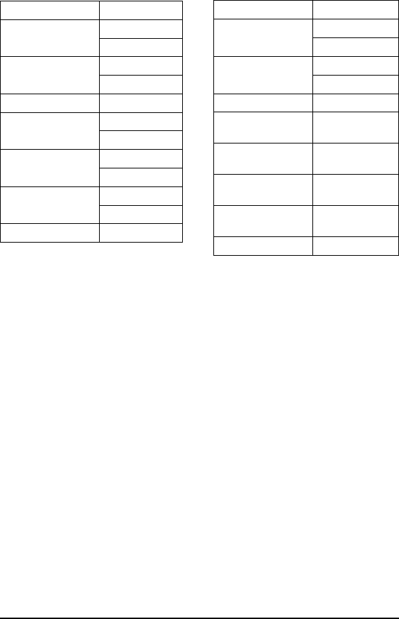
EXAMPLE:
Reads 4 bytes of data from the tag starting at address 0001H. A timeout of 2
seconds (07D0H = 2000 x 1 msec increments) is set for the completion of
the Block Read.
Copyright © 2000 Escort Memory Systems
96 LRP830-Series Long-Range Passive Reader/Writer
Command from Host
Field Contents
Header
<STX><STX>
02H
02H
Command Size 00H
07H
Command Code 05H
Start address 00H
01H
Block size 00H
04H
Timeout,
2 seconds
07H
D0H
Terminator <ETX> 03H
Response from LRP830
Field Contents
Header
<STX><STX>
02H
02H
Response Size 00H
05H
Command Echo 05H
Data from
address 0001H
05H
Data from
address 0002H
AAH
Data from
address 0003H
E7H
Data from
address 0004H
0AH
Terminator <ETX> 03H

ABxF Command 6 (06H): Block Write
DESCRIPTION
Write a block of data to an RFID tag.
DISCUSSION
The Block Write command is used to write segments of data to contiguous
areas of tag memory. It is capable of handling up to 48 bytes of data trans-
ferred to the host. The timeout value is given in 1 msec increments and can
have a value of 1EH to FFFEH (65,534 ms). When the timeout is set to 0,
the LRP830 will return a syntax error.
The Block Write command consists of a start address followed by the data to
be written to the RFID tag. If the write range exceeds the last tag address,
the LRP830 will return an invalid format error message (error code 21H).
Field Content
Header <STX><STX>
Packet Size Packet length in bytes excluding the header, command size, checksum and
terminator bytes. 0007H plus the number of data bytes
Command 06H
Start Address 2-byte value for the starting tag address
Block Size 2-byte value for the length of the write in number of bytes
Timeout 2-byte timeout value in 1 ms increments (1EH - FFFEH).
Data Data bytes to be written
Checksum Optional Checksum
Terminator <ETX>
Copyright © 2000 Escort Memory Systems
LRP830-Series Long-Range Passive Reader/Writer 97
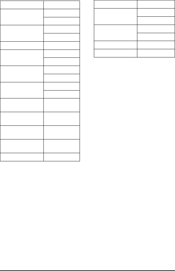
EXAMPLE:
Writes 4 bytes of data to the tag starting at address 0000H. A timeout of 2
seconds (07D0H = 2000 x 1 msec increments) is set for the completion of
the Block Write.
Copyright © 2000 Escort Memory Systems
98 LRP830-Series Long-Range Passive Reader/Writer
Command from Host
Field Contents
Header
<STX><STX>
02H
02H
Command Size 00H
0BH
Command Code 06H
Start address 00H
00H
Block Size 00H
04H
Timeout,
2 seconds
07H
D0H
Data to write to
address 0000H
52H
Data to write to
address 0001H
46H
Data to write to
address 0002H
49H
Data to write to
address 0003H
44H
Terminators <ETX> 03H
Response from LRP830
Field Contents
Header
<STX><STX>
02H
02H
Response Size 00H
01H
Command Echo 06H
Terminators <ETX> 03H

ABxF Command 7 (07H): Read Tag Serial Number
DESCRIPTION
This command retrieves the 8-byte tag serial number.
DISCUSSION
Each LRP tag has an unique (264 possible numbers) serial number. This
number can not be changed and is not part of the 48 available data bytes.
Field Content
Header <STX><STX>
Command Size Packet length in bytes excluding the header, command size, checksum and
terminator bytes. 0003H for this command
Command 07H
Timeout 2-byte timeout value in 1 ms increments (1EH - FFFEH)
Checksum Optional Checksum
Terminator <ETX>
Copyright © 2000 Escort Memory Systems
LRP830-Series Long-Range Passive Reader/Writer 99
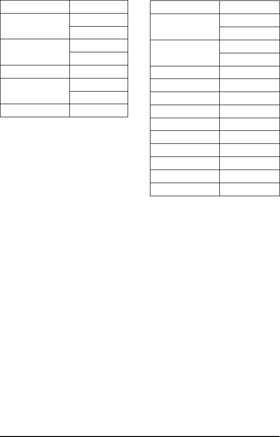
EXAMPLE:
This example will wait until a tag is in range and then reads the 8-byte iden-
tification number. In this example the SN is 1E6E3DC200000000 in hexa-
decimal.
Copyright © 2000 Escort Memory Systems
100 LRP830-Series Long-Range Passive Reader/Writer
Command from Host
Field Contents
Header
<STX><STX>
02H
02H
Command Size 00H
03H
Command Code 07H
Timeout 07H
D0H
Terminators <ETX> 03H
Response from LRP830
Field Contents
Header
<STX><STX>
02H
02H
Response Size 00H
09H
Command Echo 07H
First SN byte 1EH
Second SN byte 6EH
Third SN byte 3DH
Fourth SN byte C2H
Fifth SN byte 00H
Sixth SN byte 00H
Seventh SN byte 00H
Eighth SN byte 00H
Terminators <ETX> 03H
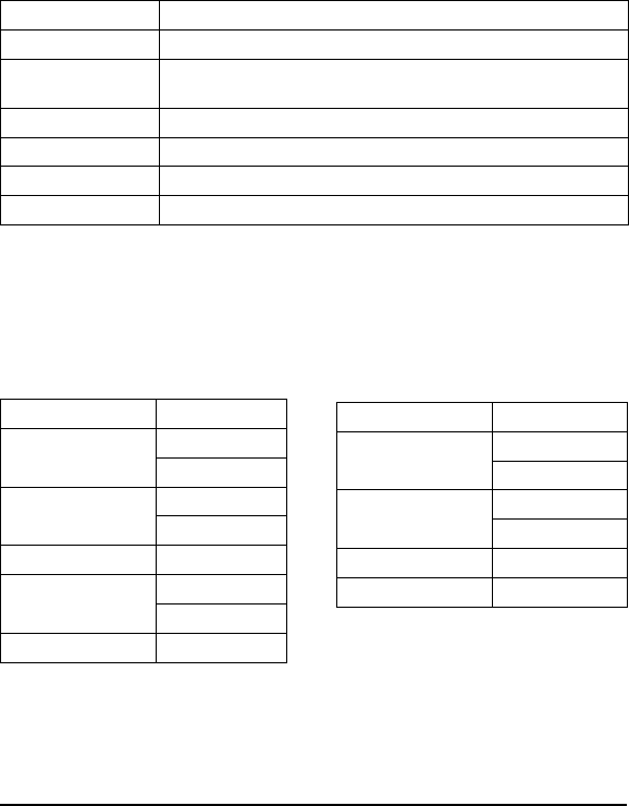
ABxF Command 8 (08H): Tag Search
DESCRIPTION
Check to see if there is an RFID tag in the LRP830 field.
DISCUSSION
This command will activate the reader/write to "look" for a tag in the RF
field. If the LRP830 finds a tag it will return a command echo to the host.
The timeout value is given in 1 msec increments and can have a value of
1EH to FFFEH (65,534 ms). When the timeout is set to 0, the LRP830 will
return a syntax error. If no tag is present it will return an error message. See
Section 6.2 for information on the error messages.
Field Content
Header <STX><STX>
Command Size Command length in bytes excluding the header, command size, checksum
and terminator bytes. 0003H for this command
Command 08H
Timeout 2-byte value for the timeout in 1 ms units (1EH - FFFEH)
Checksum Optional Checksum
Terminator <ETX>
EXAMPLE
Checks for an RFID tag in the RF field. A timeout of 2 seconds (07D0H =
2000 x 1 msec increments) is set for the completion of the Tag Search.
Copyright © 2000 Escort Memory Systems
LRP830-Series Long-Range Passive Reader/Writer 101
Command from Host
Field Contents
Header
<STX><STX>
02H
02H
Command Size 00H
03H
Command Code 08H
Timeout 07H
D0H
Terminators <ETX> 03H
Response from LRP830
Field Contents
Header
<STX><STX>
02H
02H
Response Size 00H
01H
Command Echo 08H
Terminators <ETX> 03H
ABxF Command D (0DH): Continuous Block Read
DESCRIPTION
Send block reads continuously to any tag in range of the antenna. When a
tag enters the RF field, it is read and the data passed to the host computer.
The LRP830 continues to read the tag but will not send the same data to the
host until the tag has been outside the RF field for a specified time period.
This Delay Between Identical Decodes feature prevents redundant data
transmissions when the LRP830 is in Continuous Block Read mode.
DISCUSSION
The initiate/cancel Continuous Block Read command contains three param-
eters: read length, start address, and delay between identical decodes. The
read length parameter switches the mode. Any valid, non-zero length will set
the LRP830 into Continuous Block Read mode. A read length value of 00H
will turn Continuous Block Mode off.
The Delay Between Identical Decodes value can have a value of 0 to 60
seconds. When the Delay Between Identical Decodes is set to 0, the LRP830
will continuously read AND transmit tag data to the host. This can flood the
buffers and cause communication errors and data loss.
If the LRP830 receives other commands from the host, it will execute them
and then resume Continuous Block Read mode. To exit Continuous Block
Read mode, issue the command with a read length of 0.
In Continuous Block Read mode, the LEDs will display as follows:
LED Behavior Description
ANT LED ON Assumes the Antenna is powered and functioning
CONFIG LED BLINK Tag entered the RF field
RF LED ON A tag has been read and is still in the field
RF LED OFF A read tag has been out of range for the specified time
NOTE:
This command can not be used over a DeviceNet interface.
Copyright © 2000 Escort Memory Systems
102 LRP830-Series Long-Range Passive Reader/Writer
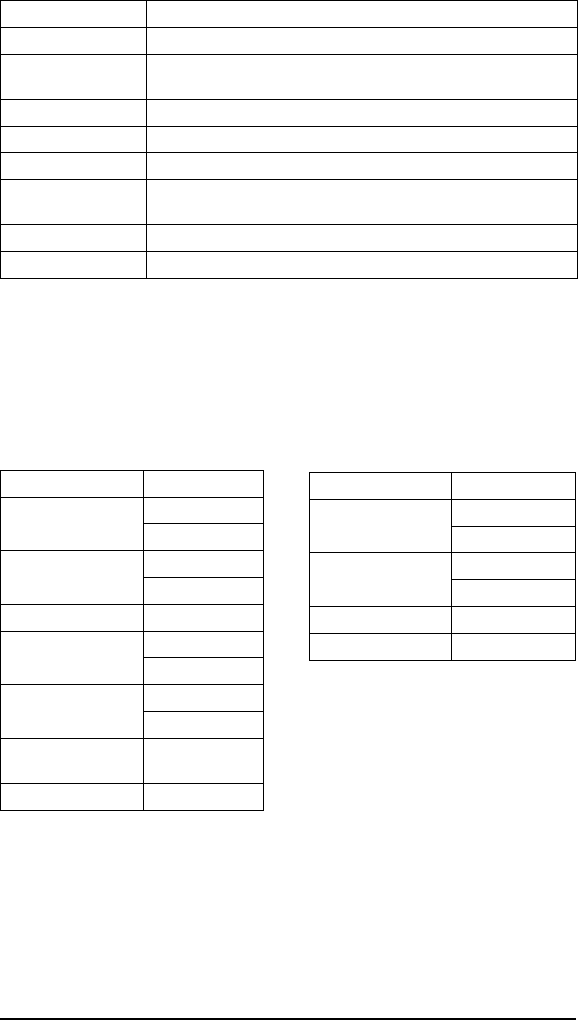
The command is formatted as follows.
Field Content
Header <STX><STX>
Command Size Command length in bytes excluding the header, command size, checksum
and terminator bytes.
Command 0DH
Start Address 2 byte value for the start address in the tag
Read Length 2 byte value for the block read length
Delay Between Identical
Reads
Delay value given in 1 second units
Checksum Optional Checksum
Terminator <ETX>
EXAMPLE
This example places the LRP830 in Continuous Block Read mode and reads
8 bytes of data from the tag starting at address 0001H. A delay between
identical reads of 2 seconds (0002H =2x1second increments) is set.
Copyright © 2000 Escort Memory Systems
LRP830-Series Long-Range Passive Reader/Writer 103
Command from Host
Field Contents
Header
<STX><STX>
02H
02H
Command Size 00H
06H
Command Code 0DH
Start Address 00H
01H
Read Length 00H
08H
Delay Between Identical
Decodes
02H
Terminator <ETX> 03H
Response from LRP830
Field Contents
Header
<STX><STX>
02H
02H
Response Size 00H
01H
Command Echo 0DH
Terminator <ETX> 03H

The LRP830 will first return an acknowledgment of the command followed
by a response containing read data when a tag enters the antenna field.
Copyright © 2000 Escort Memory Systems
104 LRP830-Series Long-Range Passive Reader/Writer
Response from LRP830
Field Contents
Header
<STX><STX>
02H
02H
Command Size 00H
09H
Command Echo 0DH
Data Byte 1 05H
Data Byte 2 AAH
Data Byte 3 E7H
Data Byte 4 0AH
Data Byte 5 05H
Data Byte 6 AAH
Data Byte 7 E7H
Data byte 8 0AH
Terminator <ETX> 03H
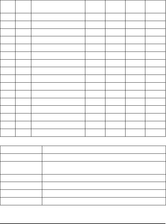
ABxF Command 10 (10H): Set Output
DESCRIPTION
Set the levels of the output lines and output LEDs "A" through "D."
DISCUSSION
This command is used to set the levels of the digital output lines using bit
logic. The four least significant bit toggle the output levels;1=ONand
0 = OFF. The following chart shows the hex values for all output high com-
binations. To reset all output, issue the command with 0000H for the Output
Pattern byte.
Field Content
Header <STX><STX>
Command Size Command length in bytes excluding the header, command size, checksum
and terminator bytes. 0002H for this command
Command 10H
Output Pattern 1 byte representing the desired output settings in bits 0-3
Checksum Optional Checksum
Terminator <ETX>
Copyright © 2000 Escort Memory Systems
LRP830-Series Long-Range Passive Reader/Writer 105
MSB LSB Remarks LSB Bit 3
Output D
LSB Bit 2
Output C
LSB Bit 1
Output B
LSB Bit 0
Output A
00H 00H Reset A, B, C, D 0000
00H 01H Set Output A - Reset B, C, D 0001
00H 02H Set Output B - Reset A, C, D 0010
00H 03H Set Output A, B - Reset C, D 0011
00H 04H Set Output C - Reset A, B, D 0100
00H 05H Set Output A, C - Reset B, D 0101
00H 06H Set Output B, C - Reset A, D 0110
00H 07H Set Output A, B, C - Reset D 0111
00H 08H Set Output D - Reset A, B, C 1000
00H 09H Set Output A, D - Reset B, C 1001
00H 0AH Set Output B, D - Reset A, C 1010
00H 0BH Set Output A, B, D - Reset C 1011
00H 0CH Set Output C, D - Reset A, B 1100
00H 0DH Set Output A, C, D - Reset B 1101
00H 0EH Set Output B, C, D - Reset A 1110
00H 0FH Set Output A, B, C, D 1111

EXAMPLE
The following example sets Output B only and resets A, C, and D.
Copyright © 2000 Escort Memory Systems
106 LRP830-Series Long-Range Passive Reader/Writer
Command from Host
Field Contents
Header
<STX><STX>
02H
02H
Command Size 00H
02H
Command Code 10H
Output Value Byte 02H
Terminator <ETX> 03H
Response from LRP830
Field Contents
Header
<STX><STX>
02H
02H
Response Size 00H
01H
Command Echo 10H
Terminator <ETX> 03H
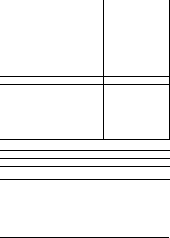
ABxF Command 11 (11H): Input Status
DESCRIPTION
Retrieves the input line levels.
DISCUSSION
This command is used to monitor the levels of the digital input lines using
bit logic. The four least significant bit display the input levels;1=ONand
0 = OFF. The following chart shows all possible conditions that can be
returned in the response.
Field Content
Header <STX><STX>
Command Size Packet length in bytes excluding the header, command size, checksum and
terminator bytes.
Command 11H
Checksum Optional Checksum
Terminator <ETX>
Copyright © 2000 Escort Memory Systems
LRP830-Series Long-Range Passive Reader/Writer 107
MSB LSB Remarks LSB Bit 3
Input D
LSB Bit 2
Input C
LSB Bit 1
Input B
LSB Bit 0
Input A
00H 00H Inputs A, B, C, D, OFF 0000
00H 01H Input A, ON - B, C, D, OFF 0001
00H 02H Input B, ON - A, C, D, OFF 0010
00H 03H Input A, B, ON - C, D, OFF 0011
00H 04H Input C, ON - A, B, D, OFF 0100
00H 05H Input A, C, ON - B, D, OFF 0101
00H 06H Input B, C, ON - A, D, OFF 0110
00H 07H Input A, B, C, ON - D, OFF 0111
00H 08H Input D, ON - A, B, C, OFF 1000
00H 09H Input A, D, ON - B, C, OFF 1001
00H 0AH Input B, D, ON - A, C, OFF 1010
00H 0BH Input A, B, D, ON - C, OFF 1011
00H 0CH Input C, D, ON - A, B, OFF 1100
00H 0DH Input A, C, D, ON - B, OFF 1101
00H 0EH Input B, C, D, ON - A, OFF 1110
00H 0FH Input A, B, C, D, ON 1111

EXAMPLE
The following example shows only Input B is ON and A, C, and D are OFF.
Copyright © 2000 Escort Memory Systems
108 LRP830-Series Long-Range Passive Reader/Writer
Command from Host
Field Contents
Header
<STX><STX>
02H
02H
Command Size 00H
01H
Command Code 11H
Terminators <ETX> 03H
Response from LRP830
Field Contents
Header
<STX><STX>
02H
02H
Response Size 00H
02H
Command Echo 11H
Input Value Byte 02H
Terminators <ETX> 03H

ABxF Command 84 (84H): Fill All
DESCRIPTION
Fill all RFID tags-in-field or all tags in the same family, with a one byte
value over multiple contiguous addresses.
DISCUSSION
This command is commonly used to clear an RFID tag's memory. It writes a
one byte value repetitively across a specified range of tag addresses. All tags
present in the antenna field with the specified Family ID will be affected by
this command. The LRP830 will return a response after the timeout expires.
The Fill All function requires one data value byte, a starting address, and a
fill length. It will fill the tag with the data value byte, starting at the specified
start address for the specified number of consecutive bytes. The Fill Length
must be set to a non-zero value (1-48).
The timeout value is given in 1 msec increments and can have a value of
1EH to FFFEH (65,534 ms). When the Anticollision Index is not zero (mul-
tiple tag-in-field enabled), the LRP830 returns a response after the timeout
expires. If the Anticollision Index is 0, a response is returned when a suc-
cessful operation is performed on 1 tag, or when the timeout has expired.
When the timeout is set to 0, the LRP830 will return a syntax error.
Field Content
Header <STX><STX>
Command Size Command length in bytes excluding the header, packet size, checksum and
terminator bytes. 0008H for this command
Command 84H
Family ID Tag Family ID - 00H = all tags
Anticollision Index Number of tags expected
Start Address 2-byte value for the starting tag address
Fill Length 2-byte value for the length of the fill in number of bytes (1-48)
Timeout 2-byte timeout value in 1 ms increments (1EH - FFFEH).
Data value byte 1 byte of fill
Checksum Optional Checksum
Terminator <ETX>
NOTE:
This command can not be used over a DeviceNet interface.
Copyright © 2000 Escort Memory Systems
LRP830-Series Long-Range Passive Reader/Writer 109
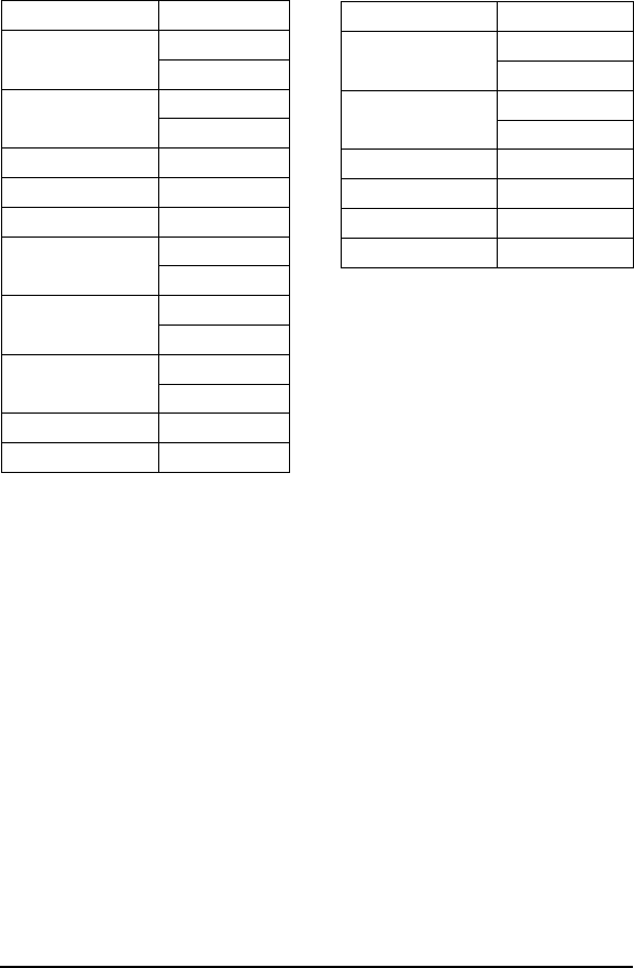
EXAMPLE
Writes 'A' (41H) to all tags with Family ID 03H, starting at address 0005H
for the following next consecutive 40 bytes. A timeout of 2 seconds (07D0H
= 2000 x 1 msec increments) is set for the completion of the configuration.
Four tags are found and filled successfully.
Copyright © 2000 Escort Memory Systems
110 LRP830-Series Long-Range Passive Reader/Writer
Command from Host
Field Bytes Contents
Header
<STX><STX>
02H
02H
Command Size 00H
0AH
Command Code 84H
Family ID 03H
Anticollision Index 02H
Start address 00H
05H
Fill Length 00H
28H
Timeout,
2 seconds
07H
D0H
Data Value Byte 41H
Terminators <ETX> 03H
Response from LRP830
Field Bytes Contents
Header
<STX><STX>
02H
02H
Response Size 00H
03H
Command Echo 84H
Numbers of tags 04H
Status byte 08H
Terminators <ETX> 03H
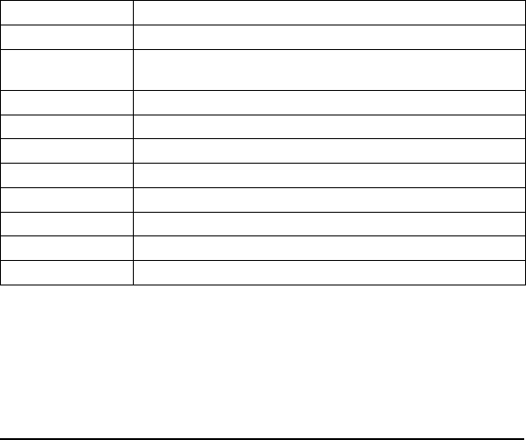
ABxF Command 85 (85H): Block Read All
DESCRIPTION
Read a block of data from all RFID tags-in-field or all those with the speci-
fied Family ID.
DISCUSSION
This command is used to read segments of data from contiguous areas of tag
memory. The timeout value is given in 1 msec increments and can have a
value of 1EH to FFFEH (65,534 ms). When the timeout is set to 0, the
LRP830 will return a syntax error.
The Block Read All consists of a Family ID, an Anticollision Index, a start
address and length, followed by a timeout value and a message terminator as
shown below.
If the read length exceeds the last tag address, the LRP830 will return an in-
valid format error message (error code 21H). A special termination packet
is sent when the timeout expires. If the Anticollision Index is set to 0, a
response is returned after successful completion of the operation to 1 tag, or
when the timeout expires. When the Anticollision Index is 0, no special ter-
mination packet is sent after timeout.
Field Content
Header <STX><STX>
Command Size Packet length in bytes excluding the header, command size, checksum and
terminator bytes.
Command 85H
Family ID Tag Family ID - 00H = all tags
Anticollision Index Number of tags expected
Start Address 2-byte value for the starting tag address
Block Size 2-byte value for the length of the read in number of bytes
Timeout 2-byte timeout value in 1 ms increments (1EH - FFFEH)
Checksum Optional Checksum
Terminator <ETX>
NOTE:
This command can not be used over a DeviceNet interface.
Copyright © 2000 Escort Memory Systems
LRP830-Series Long-Range Passive Reader/Writer 111
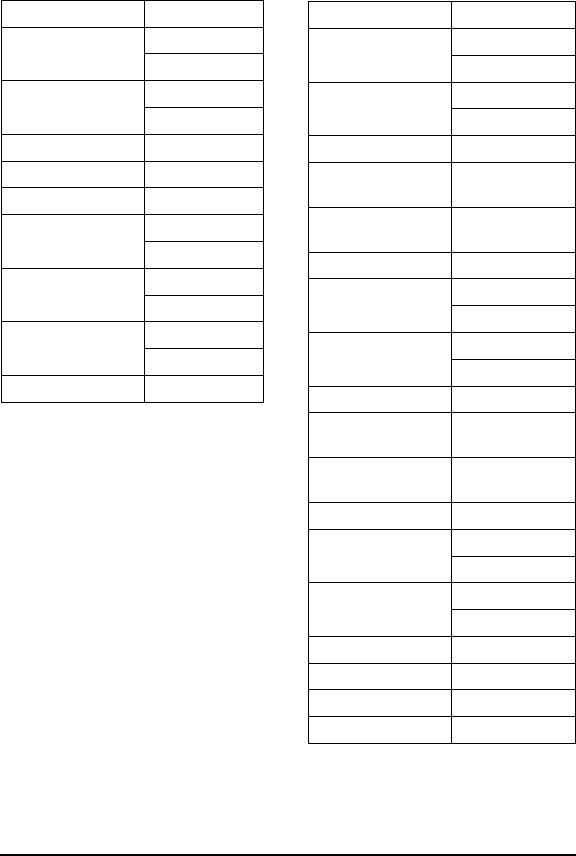
EXAMPLE:
Reads 4 bytes of data from tags with Family ID AAH, starting at address
0001H. A timeout of 2 seconds (07D0H = 2000 x 1 msec increments) is set
for the completion of the Block Read All. The Tag Family byte is set to zero
so all tags will be read. The Anticollision Index is set to 2, expecting 4-8
tags. Two tags respond with data.
Copyright © 2000 Escort Memory Systems
112 LRP830-Series Long-Range Passive Reader/Writer
Command from Host
Field Contents
Header
<STX><STX>
02H
02H
Command Size 00H
09H
Command Code 85H
Family ID AAH
Anticollision Index 02H
Start address 00H
01H
Block size 00H
02H
Timeout,
2 seconds
07H
D0H
Terminator <ETX> 03H
Response from LRP830
Field Contents
Header
<STX><STX>
02H
02H
Response Size 00H
03H
Command Echo/Tag 1 85H
Data from
address 0001H
05H
Data from
address 0002H
AAH
Terminator <ETX> 03H
Header
<STX><STX>
02H
02H
Response Size 00H
03H
Command Echo/Tag 2 85H
Data from
address 0001H
05H
Data from
address 0002H
AAH
Terminator <ETX> 03H
Header
<STX><STX>
02H
02H
Response Size 00H
03H
Command Status FFH
Number of tags 02H
Status Byte 08H
Terminator <ETX> 03H

ABxF Command 86 (86H): Block Write All
DESCRIPTION
Write a block of data to an RFID tag.
DISCUSSION
The Block Write All command is used to write segments of data to contigu-
ous areas of tag memory. The timeout value is given in 1 msec increments
and can have a value of 1EH to FFFEH (65,534 ms). When the timeout is
set to 0, the LRP830 will return a syntax error.
The Block Write All consists of a Family ID, Anticollision Index, a start ad-
dress followed by the data stream to be written to the RFID tag. If the write
range exceeds the last tag address, the LRP830 will return an invalid format
error message (error code 21H). The LRP830 will return a response when
the timeout expires. If the Anticollision Index is 0, a response is returned
when the operation is successfully completed on 1 tag, or when the timeout
expires.
Field Content
Header <STX><STX>
Command Size Packet length in bytes excluding the header, command size, checksum and
terminator bytes. 0009H plus the number of data bytes
Command 86H
Family ID Tag Family ID - 00H = all tags
Anticollision Index Number of tags expected
Start Address 2-byte value for the starting tag address
Block Size 2-byte value for the length of the write in number of bytes
Timeout 2-byte timeout value in 1 ms increments (1EH - FFFEH).
Data Data bytes to be written
Checksum Optional Checksum
Terminator <ETX>
NOTE:
This command can not be used over a DeviceNet interface.
Copyright © 2000 Escort Memory Systems
LRP830-Series Long-Range Passive Reader/Writer 113
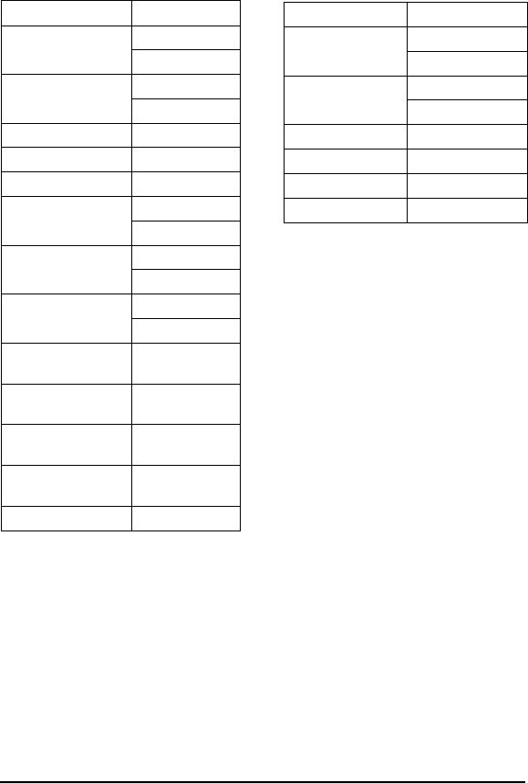
EXAMPLE:
Writes 4 bytes of data to the tag starting at address 0000H. A timeout of 2
seconds (07D0H = 2000 x 1 msec increments) is set for the completion of
the Block Write All. Family ID is set to 00H so all tags-in-field will be writ-
ten to. The Anticollision Index is 5, expecting 32-64 tags. Five tags are
written to.
Copyright © 2000 Escort Memory Systems
114 LRP830-Series Long-Range Passive Reader/Writer
Response from LRP830
Field Contents
Header
<STX><STX>
02H
02H
Response Size 00H
03H
Command Echo 86H
Ntag 05H
Status 08H
Terminators <ETX> 03H
Command from Host
Field Contents
Header
<STX><STX>
02H
02H
Command Size 00H
0DH
Command Code 86H
Family ID 00H
Anticollision Index 04H
Start address 00H
00H
Block Size 00H
04H
Timeout,
2 seconds
07H
D0H
Data to write to
address 0000H
52H
Data to write to
address 0001H
46H
Data to write to
address 0002H
49H
Data to write to
address 0003H
44H
Terminators <ETX> 03H

ABxF Command 87 (87H): Read Tag SN All
DESCRIPTION
This command retrieves the 8-byte tag serial number from all tags-in-field or
those with the specified Family ID.
DISCUSSION
Each LRP tag has an unique (264 possible numbers) serial number. This
number can not be changed and is not part of the 48 available data bytes.
The timeout value is given in 1 msec increments and can have a value of
1EH to FFFEH (65,534 ms). When the timeout is set to 0, the LRP830 will
return a syntax error. A special termination packet (starting with AAH FFH)
is sent when the timeout expires. If the Anticollision Index is set to 0, a re-
sponse is returned when the operation is successfully completed to 1 tag, or
when the timeout expires. No special termination packet is sent upon suc-
cessful completion if Anticollision Index is set to 0.
Field Content
Header <STX><STX>
Command Size Packet length in bytes excluding the head er, command size, checksum and
terminator bytes. 0005H for this command
Command 87H
Family ID Tag Family ID - 00H = all tags
Anticollision Index Number of tags expected
Timeout 2-byte timeout value in 1 ms increments (1EH - FFFEH)
Checksum Optional Checksum
Terminator <ETX>
NOTE:
This command can not be used over a DeviceNet interface.
Copyright © 2000 Escort Memory Systems
LRP830-Series Long-Range Passive Reader/Writer 115
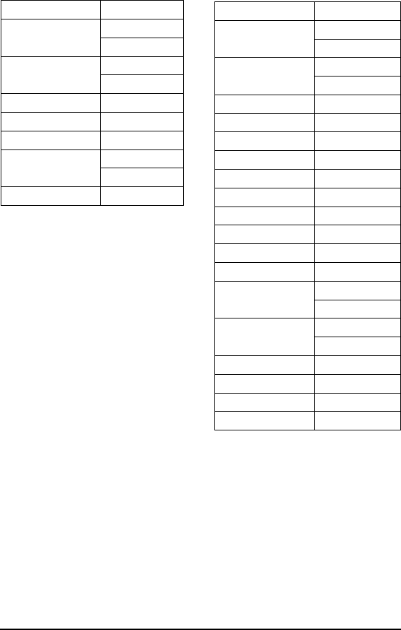
EXAMPLE:
This example will read the 8-byte serial number from all tags permitted by
the Family ID and Anticollision Index. In this example, one tag responds
and the serial number is 1E6E3DC200000000 in hexadecimal.
Copyright © 2000 Escort Memory Systems
116 LRP830-Series Long-Range Passive Reader/Writer
Command from Host
Field Contents
Header
<STX><STX>
02H
02H
Command Size 00H
05H
Command Code 87H
Family ID 00H
Anticollision Index 01H
Timeout 07H
D0H
Terminator <ETX> 03H
Response from LRP830
Field Contents
Header
<STX><STX>
02H
02H
Response Size 00H
09H
Command Echo 87H
SN byte 1 1EH
SN byte 2 6EH
SN byte 3 3DH
SN byte 4 C2H
SN byte 5 00H
SN byte 6 00H
SN byte 7 00H
SN byte 8 00H
Checksum E4H
Header
<STX><STX>
02H
02H
Response Size 00H
03H
Command Status FFH
Number of Tags 01H
Status Byte 08H
Terminator <ETX> 03H

ABxF Command 88 (88H): Tag Search All
DESCRIPTION
Check to see if there is any RFID tags in the LRP830 antenna field.
DISCUSSION
This command will activate the LRP830 to "look" for a tag in the RF field.
As soon as the LRP830 finds a tag it will return a command echo to the host.
The timeout value is given in 1 msec increments and can have a value of
1EH to FFFEH (65,534 ms). When the timeout is set to 0, the LRP830 will
return a syntax error. If no tag is present it will return an error message. See
Section 6.2 for information on the error messages.
Field Content
Header <STX><STX>
Command Size Packet length in bytes excluding the header, command size, checksum and
terminator bytes. 0005H for this command
Command 88H
Family ID Tag Family ID - 00H = all tags
Anticollision Index Number of tags expected
Timeout 2-byte value for the time in 1 ms units
Checksum Optional Checksum
Terminator <ETX>
NOTE:
This command can not be used over a DeviceNet interface.
Copyright © 2000 Escort Memory Systems
LRP830-Series Long-Range Passive Reader/Writer 117

EXAMPLE
Checks for an RFID tag in the RF field. A timeout of 2 seconds (07D0H =
2000 x 1 msec increments) is set for the completion of the Tag Search All.
A tag is found.
Copyright © 2000 Escort Memory Systems
118 LRP830-Series Long-Range Passive Reader/Writer
Command from Host
Field Contents
Header
<STX><STX>
02H
02H
Command Size 00H
05H
Command Code 88H
Family ID 00H
Anticollision Index 02H
Timeout 07H
D0H
Terminators <ETX> 03H
Response from LRP830
Field Contents
Header
<STX><STX>
02H
02H
Response Size 00H
03H
Command Echo 88H
Number of Tags 01H
Status byte 00H
Terminators <ETX> 03H
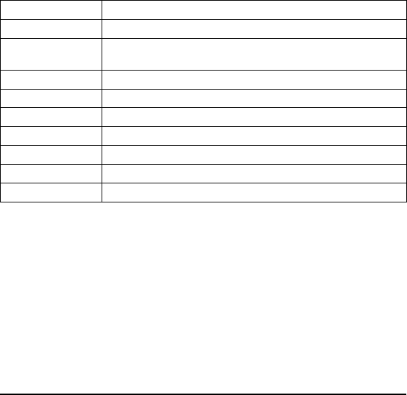
ABxF Command 89 (89H): EAS Set/Reset All
DESCRIPTION
Sets or resets the EAS feature in tag memory for all tags in range when the
command is issued.
DESCRIPTION
The commands contains a 1 byte parameter that enables or disables the EAS
feature in tags that receive the command. When the EAS Set/Reset All com-
mand is issued, the LRP830 will respond with the number of tags affected. If
the LRP830 return a 0 for Ntag it means that no tags were set or reset by the
command.
The timeout value is given in 1 msec increments and can have a value of
1EH to FFFEH (65,534 ms). When the timeout is set to 0, the LRP830 will
return a syntax error. When multiple tag-in-field is enabled (Anticollision in-
dex is not 0), the LRP830 will return a response when the timeout period ex-
pires. When multiple tag-in-field is disabled, the LRP830 will return a
response when it reads a tag or the timeout expires.
Field Content
Header <STX><STX>
Command Size Command length in bytes excluding the header, command size, checksum
and terminator bytes.
Command 89H
Family ID Tag Family ID - 00H = all tags
Anticollision Index Number of tags expected
Timeout 2-byte timeout value in 1 ms increments (1EH - FFFEH)
Set/Reset 1 = enable, 0 = disable EAS
Checksum Optional Checksum
Message Terminator <ETX>
Copyright © 2000 Escort Memory Systems
LRP830-Series Long-Range Passive Reader/Writer 119

EXAMPLE
This example assumes that the tags-in-field are not enabled for the EAS
feature. It will enabled the EAS feature for tags with Family ID 09H. The
Anticollision Index is 2, so 4-8 tags are expected in the field. When the com-
mand is issued, 5 tags with Family ID 09H are found and enabled for EAS.
Copyright © 2000 Escort Memory Systems
120 LRP830-Series Long-Range Passive Reader/Writer
Command from Host
Field Contents
Header
<STX><STX>
02H
02H
Command Size 00H
05H
Command Code 89H
Family ID 09H
Anticollision Index 02H
Timeout 07H
D0H
Set/Reset 01H
Terminator <ETX> 03H
Response from LRP830
Field Contents
Header
<STX><STX>
02H
02H
Response Size 00H
03H
Command Echo 89H
Number of Tags 05H
Status byte 08H
Terminator <ETX> 03H

ABxF Command 8A (8AH): EAS Start/Stop
DESCRIPTION
If are using the EAS feature in your application, the EAS Start/Stop com-
mand enters and exits the LRP830 from EAS mode.
DISCUSSION
When EAS mode has been started, the LRP830 will return a response when
one or more EAS-enabled tags have entered the antenna field. It will send a
second response when all EAS-enabled tags have exited the field. The com-
mand contains a control byte that toggles EAS: 1 = start, 0 = stop. A Family
ID can be set so that only EAS-enabled tags from the specified Family trig-
ger EAS responses. The Anticollision Index is ignored and should be set to
00H for this command.
The EAS mode also controls the CONFIG, ERROR and RF LEDs. The fol-
lowing table explains LED behavior.
LED(s) Behavior Description
CONFIG,
ERROR,
RF LED
OFF No EAS-enabled tag in field
CONFIG LED BLINK EAS-enabled tag entered field.
RF LED ON EAS tag has been read. LED will remain ON until all EAS tags have left
the field.
ERROR LED BLINKS Last EAS tag left the field.
IMPORTANT:
EAS mode prevents any other commands from being acknowledged or exe-
cuted until EAS has been stopped.
Field Content
Header <STX><STX>
Command Size Command length in bytes excluding the header, command size, checksum and
terminator bytes.
Command 8AH
Family ID Tag Family ID - 00H = all tags
Anticollision Index Anticollision not considered for this command, 00H
Start/Stop 1 = Start and 0 = Stop EAS
Checksum Optional Checksum
Message Terminator <ETX>
Copyright © 2000 Escort Memory Systems
LRP830-Series Long-Range Passive Reader/Writer 121
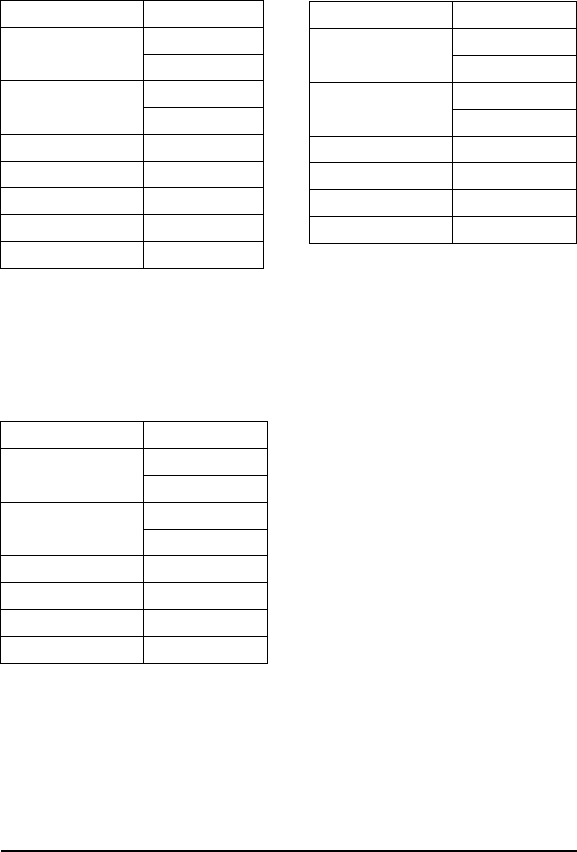
EXAMPLE
This example starts EAS mode. Three responses follow. The first is a com-
mand acknowledgment. The LRP830 sends the second when the first
EAS-enabled tag enters the field, A third response is sent when field is clear
of EAS-enabled tags. Family ID is set to 0 so that any EAS-enabled tag will
trigger responses.
When an EAS-enabled tag enters the antennas’ field, the LRP830 responds
with an EAS tag-in-field response.
Copyright © 2000 Escort Memory Systems
122 LRP830-Series Long-Range Passive Reader/Writer
Command from Host
Field Contents
Header
<STX><STX>
02H
02H
Command Size 00H
03H
Command Code 8AH
Family ID 00H
Anticollision Index 00H
Start/Stop 01H
Terminator <ETX> 03H
Response from LRP830
Field Contents
Header
<STX><STX>
02H
02H
Response Size 00H
03H
Command Echo 8AH
Number of Tags FFH
Status byte 00H
Terminator <ETX> 03H
Response from LRP830
Field Contents
Header
<STX><STX>
02H
02H
Response Size 00H
03H
Command Echo 8AH
Number of Tags 01H
Status byte 00H
Terminator <ETX> 03H

When all EAS-enabled tags have left the field, the LRP830 will send the fol-
lowing response.
Copyright © 2000 Escort Memory Systems
LRP830-Series Long-Range Passive Reader/Writer 123
Response from LRP830
Field Contents
Header
<STX><STX>
02H
02H
Response Size 00H
03H
Command Echo 8AH
Number of Tags 00H
Status byte 00H
Terminator <ETX> 03H

ABxF Command 8D (8DH): Continuous Read All
DESCRIPTION
Starts and stops Continuous Read All mode for multiple tags.
DISCUSSION
Continuous Read All mode is set by the length byte. To start Continuous
Read All mode send the command with valid, non-zero value for the length
of the read (1-48). Stop the mode by sending the command with a read
length of 0. While in this mode, any other command can be issued and it
will be handled properly. After processing the new command, the LRP will
resume the Continuous Read All mode.
The command has a parameter, tag delay, that can prevent multiple reads of
the same tag. A tag is not read a second time until a specified number of
tags have been read since it was last read. Allowed value are from 0 up to
255 (FFH), where 0 means the tag can be re-read anytime. When Continu-
ous Read All mode is interrupted with other commands, the tag delay count
is stopped during execution of the other commands and then resumed.
The LRP830 will respond with an acknowledge packet followed by data
packets for each tag read.
CONFIG LED blinks after each packet transmission.
Field Content
Header <STX><STX>
Command Size Command length in bytes excluding the header, command size, checksum and
terminator bytes.
Command 8DH
Family ID Tag Family ID - 00H = all tags
Anticollision Index Anticollision not considered for this command, 00H
Start Address Tag address for the start of the read
Read Length 1-48 = start, 0 = stop
Tag Delay Number of tags that must be read before the same tag will be read again (0-255)
Checksum Optional Checksum
Message Terminator <ETX>
NOTE:
This command can not be used over a DeviceNet interface.
Copyright © 2000 Escort Memory Systems
124 LRP830-Series Long-Range Passive Reader/Writer
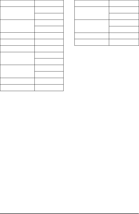
EXAMPLE
Reads 4 bytes of data from the tag starting at address 0001H. The Family ID
byte is set to zero so all tags will be read. The Anticollision Index is set to 1
so 2 to 4 tags will be expected. The Tag Delay is set to 20 (14H). Two tags
respond with read data.
Copyright © 2000 Escort Memory Systems
LRP830-Series Long-Range Passive Reader/Writer 125
Command from Host
Field Contents
Header
<STX><STX>
02H
02H
Command Size 00H
08H
Command Code 8DH
Family ID 00H
Anticollision Index 01H
Start Address 00H
01H
Read Length 00H
04H
Tag Delay 14H
Terminator <ETX> 03H
Response from LRP830
Field Contents
Header
<STX><STX>
02H
02H
Response Size 00H
01H
Command Echo 8DH
Terminator <ETX> 03H

After the LRP830 sends the acknowledgment, it will send the read data from
the 2 tags.
Copyright © 2000 Escort Memory Systems
126 LRP830-Series Long-Range Passive Reader/Writer
Response from LRP830
Field Contents
Header
<STX><STX>
02H
02H
Response Size 00H
05H
Command Echo/Tag 1 8DH
Data from
address 0001H
05H
Data from
address 0002H
AAH
Data from
address 0003H
21H
Data from
address 0004H
44H
Terminator <ETX> 03H
Header
<STX><STX>
02H
02H
Response Size 00H
05H
Command Echo/Tag 2 85H
Data from
address 0001H
05H
Data from
address 0002H
AAH
Data from
address 0003H
21H
Data from
address 0004H
44H
Terminator <ETX> 03H

ABxF Command 8E (8EH): Memory Lock All
DESCRIPTION
This command “locks” tag addresses in four byte blocks. Once bytes are
locked, they can not be unlocked.
DISCUSSION
The memory can be locked only in 4-byte blocks. The command passes
a two byte word with bits assigned to 4-byte blocks that can be locked.
Remaining bits can lock the EAS feature and the lock configuration itself.
When multiple tag-in-field is enabled (Anticollision Index is not 0), the
LRP830 will return a response when the timeout period expires. When mul-
tiple tag-in-field is disabled, the LRP830 will return a response when it locks
bytes or the timeout expires.
Attempting to write to locked bytes will return a write error timeout in the
status byte. If you write to addresses that contain both locked and
non-locked bytes, the LRP830 will return a write error in the status byte.
The configuration word formatted as shown below.
Byte Bit Description
Lock LSB 0 Tag bytes 0-3
1 Tag bytes 4-7
2 Tag bytes 8-11
3 Tag bytes 12-15
4 Tag bytes 16-19
5 Tag bytes 20-23
6 Tag bytes 24-27
7 Tag bytes 28-31
Lock MSB 8 Tag bytes 32-35
9 Tag bytes 36-39
10 Tag bytes 40-43
11 Tag bytes 44-47
12 Lock Configuration
13 Lock EAS feature
14 Reserved
15 Reserved
Copyright © 2000 Escort Memory Systems
LRP830-Series Long-Range Passive Reader/Writer 127

If a bit in the configuration word is set, then the corresponding block in the
tag is locked when the command is issued. If a bit in the configuration word
is cleared (0), then the corresponding block will not change. Once locked, a
block can not be unlocked.
The timeout value is given in 1 msec increments and can have a value of
1EH to FFFEH (65,534 ms). When the timeout is set to 0, the LRP830 will
return a syntax error.
The command is formatted as shown below.
Field Remarks
Header <STX><STX>
Command Size Command length in bytes excluding the header, command size, checksum
and terminator bytes.
Command 8EH
Family Code Tag Family ID - 00H = all tags
Anticollision index Number of tags-in-field expected
Timeout 2-byte timeout value in 1 ms increments (1EH - FFFEH)
Lock MSB Bits 8-15 of the configuration word
Lock LSB Bits 0-7 of the configuration word
Checksum Optional Checksum
Message Terminator <ETX>
Copyright © 2000 Escort Memory Systems
128 LRP830-Series Long-Range Passive Reader/Writer

EXAMPLE
This example will lock bytes 0-3 on all tags-in-field with the Family ID of
02H. Two tags are found and locked.
Copyright © 2000 Escort Memory Systems
LRP830-Series Long-Range Passive Reader/Writer 129
Command from Host
Field Contents
Header
<STX><STX>
02H
02H
Command Size 00H
07H
Command Code 8EH
Family ID 02H
Anticollision Index 01H
Timeout 07H
D0H
Lock MSB 00H
Lock LSB 01H
Terminator <ETX> 03H
Response from LRP830
Field Contents
Header
<STX><STX>
02H
02H
Response Size 00H
03H
Command Echo 8EH
Number of Tags 02H
Status byte 08H
Terminator <ETX> 03H

ABxF Command 94 (94H): SN Fill
DESCRIPTION
Fill an RFID tag, identified by serial number, with a one byte value over
multiple contiguous addresses.
DISCUSSION
This command is commonly used to clear an RFID tag's memory. It writes a
one byte value repetitively across a specified range of tag addresses.
The SN Fill command requires a specific serial number of the tag to be
filled. It will fill the tag with the data value byte, starting at the specified start
address for the specified number of consecutive bytes. When Fill Length is
set to 0, the LRP830 will write fill data from the start address to the end of
the tags memory. The timeout value is given in 1 msec increments and can
have a value of 1EH to FFFEH (65,534 ms). When the timeout is set to 0,
the LRP830 will return a syntax error.
Field Content
Header <STX><STX>
Command Size Packet length in bytes excluding the header, command size, checksum and
terminator bytes.
Command 94H
Family ID Tag Family ID - 00H = all tags
Anticollision Index Number of tags expected
Start Address 2-byte value for the starting tag address
Fill Length 2-byte value for the length of the fill in number of bytes
Timeout 2-byte timeout value in 1 ms increments (1EH - FFFEH).
Tag Serial Number 8-byte tag serial number
Data value byte 1 byte of fill
Checksum Optional Checksum
Terminator <ETX>
Copyright © 2000 Escort Memory Systems
130 LRP830-Series Long-Range Passive Reader/Writer
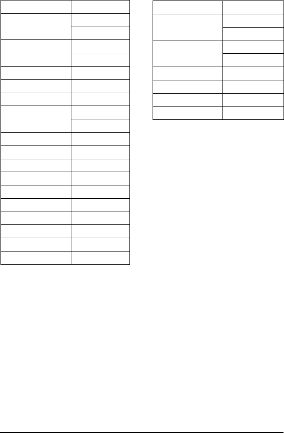
Copyright © 2000 Escort Memory Systems
LRP830-Series Long-Range Passive Reader/Writer 131
EXAMPLE
Writes 'A' (41H) to the tag specified by serial number starting at address
0005H for the following next consecutive 4 bytes. A timeout of 2 seconds
(07D0H = 2000 x 1 msec increments) is set for the completion of the config-
uration.
Command from Host
Field Contents
Header
<STX><STX>
02H
02H
Command Size 00H
0EH
Command Code 94H
Family ID 00H
Anticollision Index 02H
Timeout 07H
D0H
SN byte 1 ADH
SN byte 2 23H
SN byte 3 81H
SN byte 4 1DH
SN byte 5 C3H
SN byte 6 66H
SN byte 7 78H
SN byte 8 21H
Fill byte 41H
Terminators <ETX> 03H
Response from LRP830
Field Contents
Header
<STX><STX>
02H
02H
Response Size 00H
03H
Command Echo 94H
Number of Tags 01H
Status byte 00H
Terminators <ETX> 03H

ABxF Command 95 (95H): SN Block Read
DESCRIPTION
Read a block of data from an RFID tag.
DISCUSSION
This command is used to read segments of data from contiguous areas of tag
memory. The timeout value is given in 1 msec increments and can have a
value of 1EH to FFFEH (65,534 ms). When the timeout is set to 0, the
LRP830 will return a syntax error. A special error packet is sent if the time-
out expires.
If the read range exceeds the last tag address, the LRP830 will return an
invalid format error message (error code 21H).
Field Content
Header <STX><STX>
Command Size Packet length in bytes excluding the header, command size, checksum and
terminator bytes.
Command 95H
Family ID Tag Family ID - 00H = all tags
Anticollision Index Number of tags expected
Start Address 2-byte value for the starting tag address
Block Size 2-byte value for the length of the read in number of bytes
Timeout 2-byte timeout value in 1 ms increments (1EH - FFFEH).
Tag Serial Number 8-byte tag serial number
Checksum Optional Checksum
Terminator <ETX>
Copyright © 2000 Escort Memory Systems
132 LRP830-Series Long-Range Passive Reader/Writer

EXAMPLE:
Reads 2 bytes of data from the tag starting at address 0001H. A timeout of 2
seconds (07D0H = 2000 x 1 msec increments) is set for the completion of
the SN Block Read. If the timeout expires before reading a tag the response
packet is: 02H 02H 00 03 FF 00 Status 03H.
Copyright © 2000 Escort Memory Systems
LRP830-Series Long-Range Passive Reader/Writer 133
Command from Host
Field Contents
Header
<STX><STX>
02H
02H
Command Size 00H
11H
Command Code 95H
Family ID AAH
Anticollision Index 02H
Start address 00H
01H
Block size 00H
02H
Timeout,
2 seconds
07H
D0H
SN byte 1 ADH
SN byte 2 23H
SN byte 3 81H
SN byte 4 1DH
SN byte 5 C3H
SN byte 6 66H
SN byte 7 78H
SN byte 8 21H
Terminator <ETX> 03H
Response from LRP830, tag found
Field Contents
Header
<STX><STX>
02H
02H
Response Size 00H
03H
Command Echo 95H
Data from
address 0001H
05H
Data from
address 0002H
AAH
Terminator <ETX> 03H
Response from LRP830, tag not found
Field Contents
Header
<STX><STX>
02H
02H
Response Size 00H
03H
Command Status FFH
Ntag 00H
Status byte 08H
Terminator <ETX> 03H

ABxF Command 96 (96H): SN Block Write
DESCRIPTION
Write a block of data to an RFID tag identified by its serial number.
DISCUSSION
The SN Block Write command is used to write segments of data to contigu-
ous areas of tag memory. The timeout value is given in 1 msec increments
and can have a value of 1EH to FFFEH (65,534 ms). When the timeout is
set to 0, the LRP830 will return a syntax error.
The SN Block Write consists of a start address followed by the data stream
to be written to the RFID tag specified by the serial number given in the
command. If the block size exceeds the last tag address, the LRP830 will
return an invalid format error message (error code 21H).
Field Content
Header <STX><STX>
Command Size Command length in bytes excluding the header, packet size, checksum and
terminator bytes.
Command 96H
Family ID Tag Family ID - 00H = all tags
Anticollision Index Number of tags expected
Start Address 2-byte value for the starting tag address
Block Size 2-byte value for the length of the write in number of bytes
Timeout 2-byte timeout value in 1 ms increments (1EH - FFFEH).
Tag Serial Number 8-byte tag serial number
Data Data bytes to be written
Checksum Optional Checksum
Terminator <ETX>
Copyright © 2000 Escort Memory Systems
134 LRP830-Series Long-Range Passive Reader/Writer

EXAMPLE:
Writes 4 bytes of data to the tag starting at address 0000H. A timeout of 2
seconds (07D0H = 2000 x 1 msec increments) is set for the completion of
the SN Block Write.
Copyright © 2000 Escort Memory Systems
LRP830-Series Long-Range Passive Reader/Writer 135
Command from Host
Field Contents
Header
<STX><STX>
02H
02H
Command Size 00H
15H
Command Code 96H
Family ID 03H
Anticollision Index 03H
Start address 00H
00H
Block Size 00H
04H
Timeout,
2 seconds
07H
D0H
SN byte 1 ADH
SN byte 2 23H
SN byte 3 81H
SN byte 4 1DH
SN byte 5 C3H
SN byte 6 66H
SN byte 7 78H
SN byte 8 21H
Data to write to
address 0000H
52H
Data to write to
address 0001H
46H
Data to write to
address 0002H
49H
Data to write to
address 0003H
44H
Terminators <ETX> 03H
Response from LRP830
Field Contents
Header
<STX><STX>
02H
02H
Response Size 00H
03H
Command Echo 96H
Number of tags 01H
Status byte 00H
Terminators <ETX> 03H

ABxF Command 97 (97H): SN Block Read All
DESCRIPTION
Read a block of data from all RFID tags-in-field or all those with the speci-
fied Family ID. Data will be returned with the serial number of the corre-
sponding tag.
DISCUSSION
This command is used to read segments of data from contiguous areas of tag
memory. It is capable of handling up to 48 bytes of data transferred to the
host with one command if there is no tag family ID. The timeout value is
given in 1 msec increments and can have a value of 1EH to FFFEH (65,534
ms). When the timeout is set to 0, the LRP830 will return a syntax error.
The response to this command will contain the serial number of the respond-
ing tags preceding the data from those tags. The termination packet is trans-
mitted when the timeout expires. Each packet will be sent to the host as soon
as it is available. The returned serial numbers can be used to read/write to
tags-in-field via the SN Block Read/Write command.
The SN Block Read All consists of a Family ID, an Anticollision Index, a
start address and length, followed by a timeout value and a message termina-
tor <ETX> as shown below. A special termination packet is sent when the
timeout expires. If the Anticollision Index is 0, a response is returned when
the operation is successfully completed on 1 tag, or when the timeout ex-
pires. A termination packet is not sent for successful completion if the
Anticollision Index is 0.
If the read length exceeds the last tag address, the LRP830 will return an
invalid format error message (error code 21H).
Copyright © 2000 Escort Memory Systems
136 LRP830-Series Long-Range Passive Reader/Writer

The command is formatted as follows.
Field Content
Header <STX><STX>
Command Size Packet length in bytes excluding the header, command size, checksum and
terminator bytes.
Command 97H
Family ID Tag Family ID - 00H = all tags
Anticollision Index Number of tags expected
Start Address 2-byte value for the starting tag address
Block Size 2-byte value for the length of the read in number of bytes
Timeout 2-byte timeout value in 1 ms increments (1EH - FFFEH).
Checksum Optional Checksum
Terminator <ETX>
NOTE:
This command can not be used over a DeviceNet interface.
Copyright © 2000 Escort Memory Systems
LRP830-Series Long-Range Passive Reader/Writer 137
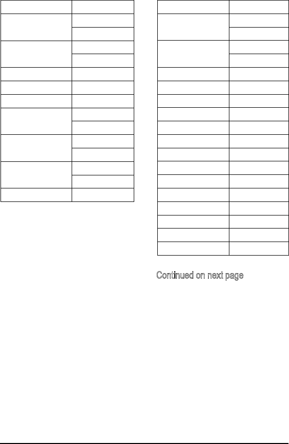
EXAMPLE:
Reads 4 bytes of data from the tag starting at address 0001H. A timeout of 2
seconds (07D0H = 2000 x 1 msec increments) is set for the completion of
the SN Block Read All. The Tag Family byte is set to zero so all tags will be
read. Three tags respond with data.
Copyright © 2000 Escort Memory Systems
138 LRP830-Series Long-Range Passive Reader/Writer
Command from Host
Field Contents
Header
<STX><STX>
02H
02H
Command Size 00H
09H
Command Echo 97H
Family ID 03H
Anticollision Index 00H
Start address 00H
00H
Block Size 00H
04H
Timeout,
2 seconds
07H
D0H
Terminators <ETX> 03H
Response from LRP830
Field Contents
Header/tag 1
<STX><STX>
02H
02H
Response Size 00H
0DH
Command Code 97H
SN byte 1/tag 1 ADH
SN byte 2/tag 1 23H
SN byte 3/tag 1 81H
SN byte 4/tag 1 1DH
SN byte 5/tag 1 C3H
SN byte 6/tag 1 66H
SN byte 7/tag 1 78H
SN byte 8/tag 1 21H
Data byte 1/tag 1 52H
Data byte 2/tag 1 46H
Data byte 3/tag 1 49H
Data byte 4/tag 1 44H
Terminators <ETX> 03H
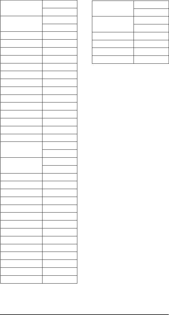
Copyright © 2000 Escort Memory Systems
LRP830-Series Long-Range Passive Reader/Writer 139
Header/tag 2
<STX><STX>
02H
02H
Response Size 00H
0DH
Command Code 97H
SN byte 1/tag 2 ADH
SN byte 2/tag 2 23H
SN byte 3/tag 2 81H
SN byte 4/tag 2 1DH
SN byte 5/tag 2 C3H
SN byte 6/tag 2 66H
SN byte 7/tag 2 78H
SN byte 8/tag 2 21H
Data byte 1/ tag 2 52H
Data byte 2/tag 2 46H
Data byte 3/tag 2 49H
Data byte 4/tag 2 44H
Terminators <ETX> 03H
Header/tag 3
<STX><STX>
02H
02H
Response Size 00H
0BH
Command Code 97H
SN byte 1/tag 3 ADH
SN byte 2/ tag 3 23H
SN byte 3/tag 3 81H
SN byte 4/tag 3 1DH
SN byte 5/tag 3 C3H
SN byte 6/tag 3 66H
SN byte 7/tag 3 78H
SN byte 8/tag 3 21H
Data byte 1/ tag 3 52H
Data byte 2/tag 3 46H
Data byte 3/tag 3 49H
Data byte 4/tag 3 44H
Terminators <ETX> 03H
Header/End Packet
<STX><STX>
02H
02H
Response Size 00H
03H
Command Echo FFH
Number of tags 03H
Status byte 08H
Terminators <ETX> 03H
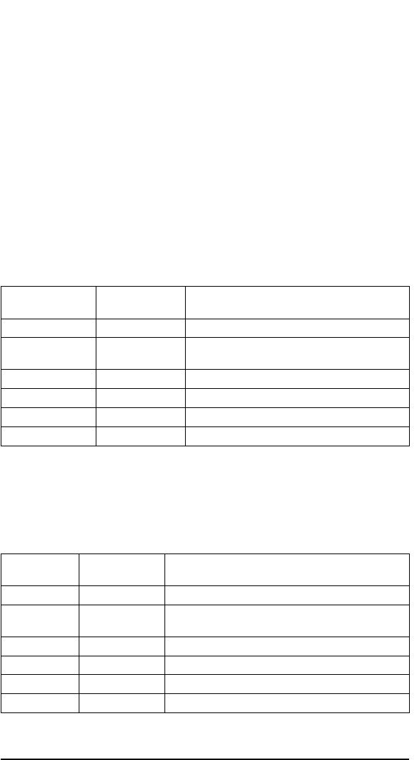
6.5 ABx ASCII Protocol
The ABx ASCII Protocol is based on the ABx Fast protocol. It uses the
same headers and terminator (already ASCII characters) and converts the
hex value of command and data bytes to printable ASCII (2 digit Hexadeci-
mal notation). In another words, the hex values given in an ABx Fast com-
mand are transmitted as separate ASCII characters.
Since it is an ASCII protocol, the Xon/Xoff handshake can be used.
Command Packet Structure:
The command protocol is based on the following minimal packet structure.
The data field and the checksum may not be present depending on the com-
mand type and your checksum setting.
Field
Number of ASCII
Characters Content
Header 2 <STX><STX> (02H, 02H)
Command Size 4 Packet length in bytes excluding the header, Command
size, checksum and terminator bytes.
Command 2 Command Code
(Data) variable command data/parameters
Checksum 2 Optional Checksum
Terminator 1 <ETX> (03H)
Following a successful operation, the LRP830 will respond with the follow-
ing. The data field and the checksum may not be present depending on the
command and your checksum setting. If a checksum is enabled in the Con-
figuration Menu, then it is always present for every command.
Field
Number of ASCII
Characters Content
Header 2 <STX><STX> (02H, 02H)
Response Size 4 Packet length in bytes excluding the header, response size,
checksum and terminator bytes.
Command 2 Command Echo
(Data) variable response data
Checksum 2 Optional Checksum
Terminator 1 <ETX> (03H)
Copyright © 2000 Escort Memory Systems
140 LRP830-Series Long-Range Passive Reader/Writer
6.6 ABx ASCII Protocol

If the LRP830 encounters a fault it will respond with the following:
Field
Number of ASCII
Characters Content
Header 2 <STX><STX> (02H, 02H)
Response Size 4 Packet length in bytes excluding the header, response size,
checksum and terminator bytes.
Error Flag 2 FFH
Error Code 2 Hex error code, see Table 11 for details
Checksum 2 Optional checksum
Terminator 1 <ETX> (03H)
Most RF operations will also require additional parameters and data that will
be included in the command stream between the command code or echo and
the terminator.
The Header and Terminator are always STX and ETX respectively. Any
other field value is in ASCII hex notation. Allowed values: '0'-'9', 'A'-'F'. Ex-
ample: the value ABH (decimal 171) in ASCII protocol is transmitted as a
2-character string «AB», i.e. the 2 bytes: 41H 42H (ASCII values for 'A' and
'B'). The hex value of the hex digits given in ASCII are: '0'-'9' = 30H - 39H,
'A'-'F' = 41H-46H.
The sequence for each command is given with the response format in the
preceding section. Referring to the ABx Fast command you can structure the
ABx ASCII commands by using ASCII values for each digit of the hex val-
ues, excluding the header and terminator that are already ASCII characters.
Command/Response Size
The ABx ASCII requires the length of the packet be included in the com-
mand. All parameters and data between the Command Size and the termi-
nator or checksum byte must be accounted for in the packet size word. This
includes all command codes and parameters such as field definition for
Block Read/Writes. The packet size remains the same with, or without the
checksum.
Copyright © 2000 Escort Memory Systems
LRP830-Series Long-Range Passive Reader/Writer 141

Checksum
The optional checksum must be enabled from the operating mode menu to
be available. The checksum is calculated by adding all the byte values (not
the ASCII translation values) in the packet (less the values in the header,
checksum if present, and terminator), discarding byte overflow and subtract-
ing the byte sum from FFH.
Example ASCII Command
Fill Tag
This command fills the specified number of cells from the specified start ad-
dress with the specified value. Block size = 0 means filling to the end of the
memory. The command will take the same form as the ABx Fast command.
Field Content
Header <STX><STX>
Command Size Packet length in bytes excluding the header, command size, checksum and
terminator bytes. Given as four ASCII character value. 0008H for this com-
mand
Command <30H><34H> (04)
Start Address 4 ASCII character value for the starting tag address
Fill Length 4 ASCII character value for the length of the fill in number of bytes
Timeout 4 ASCII character value for timeout in 1 ms units.
Data value byte 2 ASCII character value for 1 byte of fill
Checksum 2 ASCII character value for Optional Checksum
Terminator <ETX>
Copyright © 2000 Escort Memory Systems
142 LRP830-Series Long-Range Passive Reader/Writer
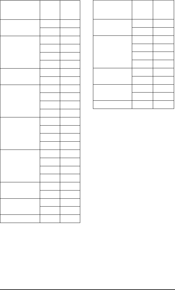
The ASCII character string for a fill of 32 bytes, from address 0 with 55H
value, timeout 5 sec., follows.
Copyright © 2000 Escort Memory Systems
LRP830-Series Long-Range Passive Reader/Writer 143
Command from Host
Field ASCII
Hex
Value
ASCII
String
Header
<STX><STX>
02H STX
02H STX
Command Size 30H 0
30H 0
30H 0
38H 8
Command 30H 0
34H 4
Start Address 30H 0
30H 0
30H 0
30H 0
Fill Length 30H 0
30H 0
32H 2
30H 0
Timeout Value 31H 1
33H 3
38H 8
38H 8
Data Byte Value 35H 5
35H 5
Checksum 45H E
33H 3
Terminators <ETX> 03H ETX
Response from LRP830
Field ASCII
Hex
Value
ASCII
String
Header
<STX><STX>
02H STX
02H STX
Response Size 30H 0
30H 0
31H 1
30H 0
Command Echo 30H 0
34H 4
Checksum 46H F
41H A
Terminators <ETX> 03H ETX

7LRP830 DEVICENET INTERFACE
7.1 Introduction
The LRP830 is compatible with any DeviceNet scanner host that conforms
to DeviceNet standards and can process standard DeviceNet fragmentation
protocol as defined by the Open DeviceNet Vendor Association (ODVA) in
the ODVA DeviceNet specification (see www.odva.org for details.) You
may address DeviceNet protocol and scanner questions to "Dr. DeviceNet"
at the ODVA Web site.
An EDS (Electronic Data Sheet) configuration file is provided with the
LRP830 software for use with the Allen-Bradley DeviceNet Manager PLC
scanner configuration software or any other conforming DeviceNet scanner
host. The is EDS text file contains standard vendor specific information for
the Escort Memory Systems' LRP830 product. Please refer to the
"readme.txt" text files on the release diskette for more information.
Any command packet sent from the host and any response packet sent by
the controller back to the host is structured as an 8 byte fixed length packet.
The LRP830 supports larger message sizes using the standard DeviceNet
message fragmentation technique. When the interface board I/O produce
size and/or I/O consume size is greater than 8 bytes, fragmentation is auto-
matically performed by the controller software.
Scan Rates
The user determines the DeviceNet poll frequency via the DeviceNet scan-
ner host configuration program, such as A-B DeviceNet Manager software.
For example, the DeviceNet Manager program uses a default poll (scan) rate
of 10 milliseconds (version 3.004). LRP830 DeviceNet communications
may be lost if the poll rate is set above 500 milliseconds. The interscan
delay rate of the DeviceNet scanner host should not be set less than 150 ms
for the LRP830(s). If other DeviceNet nodes require a faster poll rate, use
the standard background polling option for LRP830 nodes so that the back-
ground poll rate does not exceed 150 ms.
Copyright © 2000 Escort Memory Systems
144 LRP830-Series Long-Range Passive Reader/Writer
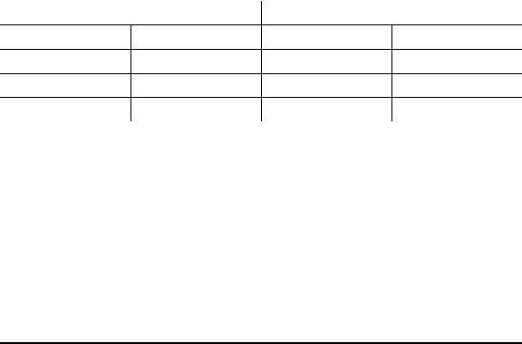
COM1 LED Indicator
The COM1 LED indicates DeviceNet traffic activity. The LED does not in-
dicate network status as defined by ODVA.
DeviceNet Interface
To use the DeviceNet interface:
1. Set DIP switch 4 on the main board to "1" (ON) to enable
DeviceNet communications.
2. Verified default settings of serial port COM2: 9600, N, 8, 1, no
flow control for configuration purposes.
7.2 Interface Board Monitor Mode
The following Section describes steps required to enter the DeviceNet Inter-
face Board Monitor mode. From the Monitor Menu you can download up-
dated LRP830 DeviceNet interface software, see the current configuration,
and change the DeviceNet protocol parameters.
Enter Interface Board Monitor
To enter the Interface Board Monitor follow these steps:
1. Connect LRP830 COM2 (see below) to one of your PC serial
communication ports.
LRP830 Standard PC Serial Port
COM2 Pin Number Signal Name DB9 Pin Number Signal Name
RTX2 RX
PRX3TX
M GND 5 GND
2. Install and run EC (at 9600, N, 8, 1), to establish communication
with the LRP830. EC is a serial communications program and is
available on diskette or can be downloaded from Escort Memory
Systems’ web site, www.ems-rfid.com.
3. Power the LRP830 via the DeviceNet connector. Refer to Section
3.8 for more information on powering the LRP830.
Copyright © 2000 Escort Memory Systems
LRP830-Series Long-Range Passive Reader/Writer 145

4. You must press CTRL-E within 7 seconds to enter the Interface
Board Monitor mode from a terminal emulator (EC) connected to
COM port 2 (9600, N, 8, 1). If the LRP830 does not receive
CTRL-E in the seven second period, it will automatically enter
"RUN MODE".
5. Upon entering CTRL-E, wait for the following menu to appear.
————————————————————————————
| HMS/LRP Rd/Wrt Controller with DeviceNet & Serial I/O. |
| (c) 2000 Escort Memory Systems, a Datalogic Co. |
————————————————————————————-
Commands:
I <cr> ———— Display Configuration Info
E <cr> ———— Edit Configuration Sub-menu
Z <cr> ———— Download Firmware Hex File (config defaults)
X <cr> ———— Download Firmware Hex File (retain config)
RESET ———— To enter Run Mode (exit monitor)
>x
Note: "X" is the recommended option for new firmware download by the user. No download option will
overwrite the DeviceNet serial number set at the factory (V2.0F and above). Commands are not case sen-
sitive.
*:-D Initiate download now (do not restart prior to RESET msg.)*
CTRL-E places the main board in a special mode, that allows the Main
Board to pass communications to the interface board during Monitor Mode.
NOTE:
After Monitor Mode has been entered via CTRL-E within 7 seconds, you
must reset the device to enter Run Mode. Run Mode is entered automatically
if no control key actions are performed.
Copyright © 2000 Escort Memory Systems
146 LRP830-Series Long-Range Passive Reader/Writer

7.2.1 Downloading Firmware to the Interface Board
To download new software to the interface board, select "X" from the Moni-
tor Menu shown above to retain existing configuration settings or "Z" if you
wish to overwrite configuration settings with factory defaults. In most cases
you will want to retain existing configuration settings and should use the X
command to download new firmware.
IMPORTANT:
It is not necessary to download firmware into the unit unless instructed to do
so by Escort Memory Systems technical support personnel.
————————————————————————————-
| HMS/LRP Rd/Wrt Controller with DeviceNet & Serial I/O. |
| (c) 2000 Escort Memory Systems, a Datalogic Co. |
————————————————————————————-
Commands:
I <cr> ———— Display Configuration Info
E <cr> ———— Edit Configuration Sub-menu
Z <cr> ———— Download Firmware Hex File (config defaults)
X <cr> ———— Download Firmware Hex File (retain config)
RESET ———— To enter Run Mode (exit monitor)
>x
Note: "X" is the recommended option for new firmware download by the user. No download option will
overwrite the DeviceNet serial number set at the factory.
*:-D Initiate download now (do not restart prior to RESET msg.)*
Copyright © 2000 Escort Memory Systems
LRP830-Series Long-Range Passive Reader/Writer 147

7.2.2 Downloading with the EC Emulation Program
If you are using the terminal emulator "EC" provided by Escort Memory
Systems (EMS), do the following from EC to download the new software:
1. Perform ALT-F to enter the file menu.
2. Select "download" from the menu.
3. Select "ASCII" from the pop-up window.
4. Specify the path/name of the hex file provided by Escort Memory
Systems.
When the download is complete, you will be prompted to reset
the LRP830 with the following message:
<:-> RESET NOW...
5. Repower the LRP830.
7.2.3 Display Interface Board Configuration
Parameters
The following display reflects the current configuration parameters that are
stored in the unit's non-volatile flash ROM. Some of the parameters can be
modified via the Configuration Edit option "E" (see next Section).
SW1 positions 7 and 8 can be used to set the DeviceNet baud rate as fol-
lows:
00 = 125k (default)
01 = 250k
10 = 500k
Please refer to the ODVA DeviceNet Specification for additional informa-
tion.
Copyright © 2000 Escort Memory Systems
148 LRP830-Series Long-Range Passive Reader/Writer

Display Configuration Info
To review the current settings enter "I" from the Monitor Menu and you will
see a display similar to the following:
—————————————————————————————————
| HMS/LRP Rd/Wrt Controller with DeviceNet & Serial I/O. |
| (c) 2000 Escort Memory Systems, a Datalogic Co. |
———————————————————————————————-——
Commands:
I <cr> ———— Display Configuration Info
E <cr> ———— Edit Configuration Sub-menu
Z <cr> ———— Download Firmware Hex File (config defaults)
X <cr> ———— Download Firmware Hex File (retain config)
RESET ——— To enter Run Mode (exit monitor)
> I (case insensitive)
The following display contains the default (factory) recommended configu-
ration:
LRP830 Firmware Version V2.0F DeviceNet Serial # 04 99 00 0A (hex).
<============= LRP830 INTERFACE-BOARD CONFIGURATION DATA =============>
I/O produce size: 34 I/O consume size: 34 Device Type: HDR
DevNet Protocol: POLL ABx separation: Y
Buf Flush Enable: N Buf Flush Delay: 200
DNet Rev: 002.000 MAC_ID: 10
Vendor ID: 78 Product Code: 830 Product Type: 12
========================================================================
Edit Configuration Menu (y/n)?> y
If your requirements necessitate changing the configuration, enter "Y" at the
above prompt. The configuration editor will appear as described in the fol-
lowing section.
Copyright © 2000 Escort Memory Systems
LRP830-Series Long-Range Passive Reader/Writer 149

7.2.4 Interface Board Configuration Editor
Note: the following menu can be attained via "Y" (above) or selecting "E"
from the Monitor Menu (above). These are the recommended parameters,
however, it is likely that A and/or B (below) may require modification ac-
cording to customer requirements.
<= LRP830 INTERFACE-BOARD CONFIGURATION MENU =>
Enter Parameter # to Change:
===== Std DeviceNet =====
90 A. 830 Tx Msg Size (0-254)
90 B. 830 Rx Msg Size (0-254)
0 C. DevNet Protocol (Poll=0,Strobe=1)
D. DeviceNet Serial# 04 99 12 34 (hex)
===== LRP830 Specific =====
2 1. Device Type (GENeric: 0=norm, 1=rev; HDR: 2=n, 3=r)
Y 2. ABx separation (Y/N)
N 3. Buf Flush Enable (Y/N)
200 4. Buf Flush Delay (0-9999)
SELECTION 1-C? (Ctrl-C Exits)
When you wish to exit the interface board configuration menu, enter
"CTRL-C." The following prompt will appear which is responded with "n"
in this example.
Update Flash ROM (y/n)?> n [:-( Flash ROM *Not* Updated )-:]
{-:) Please Reset LRP830 to enter RUN mode (:-}
{HALTED}
<RESET>
The LRP830 must now be reset or power cycled to enable the unit to enter
"RUN" mode.
Copyright © 2000 Escort Memory Systems
150 LRP830-Series Long-Range Passive Reader/Writer

7.2.5 Edit Configuration Command.
To change the LRP830 configuration parameters, enter the "E" command
from the Monitor Menu. The Interface Board will display the current values
for user-configureable variables. In the following configuration menu, range
checking and validation is performed on every input provided by the user.
The current value of the item is displayed with each prompt for change.
ESC exits to a previous level. The backspace key is supported. CTRL-C ex-
its the Configuration Menu and prompts you to store the changes into flash
(non-volatile) memory.
————————————-—————————————————————
| HMS/LRP Rd/Wrt Controller with DeviceNet & Serial I/O. |
| (c) 2000 Escort Memory Systems, a Datalogic Co. |
————————————-—————————————————————
Commands:
I <cr> ———— Display Configuration Info
E <cr> ———— Edit Configuration Sub-menu
Z <cr> ———— Download Firmware Hex File (config defaults)
X <cr> ———— Download Firmware Hex File (retain config)
RESET ———— To enter Run Mode (exit monitor)
>e
Note: the following display reflects the current status of user configureable
parameters. The display will refresh automatically after you enter a new
value.
Enter the number or letter corresponding to the variable you wish to change
followed by the new value. After you have entered and visually verified all
of your modifications, enter <CTRL-C> and select "Y" to save your
changes to the LRP830's flash memory.
LRP830 Firmware Version V2.0F DeviceNet Serial # 04 99 00 0A (hex).
<= LRP830 INTERFACE-BOARD CONFIGURATION MENU =>
Enter Parameter # to Change:
===== Std DeviceNet =====
90 A. 830 Tx Msg Size (0-254)
90 B. 830 Rx Msg Size (0-254)
0 C. DevNet Protocol (Poll=0,Strobe=1)
D. DeviceNet Serial# 04 99 12 34 (hex)
===== LRP830 Specific =====
2 1. Device Type (GENeric: 0=norm, 1=rev; HDR: 2=n, 3=r)
Y 2. ABx separation (Y/N)
N 3. Buf Flush Enable (Y/N)
200 4. Buf Flush Delay (0-9999)
SELECTION 1-C? (Ctrl-C Exits)
Copyright © 2000 Escort Memory Systems
LRP830-Series Long-Range Passive Reader/Writer 151

Example
The following example shows how the Tx and Rx message sizes are modi-
fied from 90 to 48 bytes in length.
SELECTION 1-C? (Ctrl-C Exits) a
90 A. 830 Tx Msg Size (0-254). ?>48
Enter Parameter # to Change:
===== Std DeviceNet =====
48 A. 830 Tx Msg Size (0-254)
90 B. 830 Rx Msg Size (0-254)
0 C. DevNet Protocol (Poll=0,Strobe=1)
D. DeviceNet Serial# 04 99 12 34 (hex)
===== LRP830 Specific =====
2 1. Device Type (GENeric: 0=norm, 1=rev; HDR: 2=n, 3=r)
Y 2. ABx separation (Y/N)
N 3. Buf Flush Enable (Y/N)
200 4. Buf Flush Delay (0-9999)
SELECTION 1-C? (Ctrl-C Exits) b
90 B. 830 Rx Msg Size (0-254). ?>48
Enter Parameter # to Change:
===== Std DeviceNet =====
48 A. 830 Tx Msg Size (0-254)
48 B. 830 Rx Msg Size (0-254)
0 C. DevNet Protocol (Poll=0,Strobe=1)
D. DeviceNet Serial# 04 99 12 34 (hex)
===== LRP830 Specific =====
2 1. Device Type (GENeric: 0=norm, 1=rev; HDR: 2=n, 3=r)
Y 2. ABx separation (Y/N)
N 3. Buf Flush Enable (Y/N)
200 4. Buf Flush Delay (0-9999)
SELECTION 1-C? (Ctrl-C Exits) "CTRL-C" entered by user
Update Flash ROM (y/n)?> y {:->! Flash ROM Updated !<-:}
{-:) Please Reset LRP830 to enter RUN mode (:-}
{HALTED}
<RESET>
When reset is requested via a monitor mode function, you must reset the
LRP830 and let the seven second period elapse without entering anything
from the keyboard to enter Run Mode.
Copyright © 2000 Escort Memory Systems
152 LRP830-Series Long-Range Passive Reader/Writer

7.2.6 Configuration Parameter Validation
<= LRP830 INTERFACE-BOARD CONFIGURATION MENU =>
Enter Parameter # to Change:
===== Std DeviceNet =====
90 A. 830 Tx Msg Size (0-254)
90 B. 830 Rx Msg Size (0-254)
0 C. DevNet Protocol (Poll=0,Strobe=1)
D. DeviceNet Serial# 04 99 12 34 (hex)
===== LRP830 Specific =====
2 1. Device Type (GENeric: 0=norm, 1=rev; HDR: 2=n, 3=r)
Y 2. ABx separation (Y/N)
N 3. Buf Flush Enable (Y/N)
200 4. Buf Flush Delay (0-9999)
SELECTION 1-C? (Ctrl-C Exits)
Begin by selecting the letter or number associated with the parameter to be
changed. After entry of the desired option, a prompt will appear with an
allowable limits range. Enter the desired value after the modification prompt
appears.
For example:
Selection (CTRL-C to exit) ...a
If an invalid value is entered, the monitor displays an error message and
re-prompts for a valid entry.
For example; if an invalid value is entered for LRP830 Transmit Message
Size (i.e., I/O produce size), the monitor responds with a limits prompt.
34 A. 830 Tx Msg Size (0-254). ?>487
34 **Must be 0-253 A. 830 Tx Msg Size (0-254). ?>48
The leftmost column contains the current parameter setting. Upon entering a
valid parameter the monitor will return to the Configuration Menu where the
value will be updated in the list of options.
Parameters are separated into two categories: Standard DeviceNet and
LRP830 Specific. Following is an explanation of each parameter setting.
Copyright © 2000 Escort Memory Systems
LRP830-Series Long-Range Passive Reader/Writer 153

7.2.7 Standard DeviceNet Parameters
Produce and Consume Sizes
Before setting the first two parameters (TxMsgSize and RxMsgSize) you
should calculate the optimum consume and produce sizes. The default size is
90 for both TxMsg and RxMsg.
The default setting will create a byte offset for the command code byte when
using ABx Fast and a word oriented PLC.
ABx Standard has a different header then the ABx Fast protocol and if a
HDR (header protocol) has been selected, then you must add 2 handshake
bytes into the calculation.
NOTE:
For the sake of clarity, the DeviceNet Header in HDR mode is referred to as
the handshake word in the following documentation.
Commands in the ABx Non-separated mode permit more data in the re-
sponses because of the packed nature of the return data in this mode. Please
refer to Section 7.2.8 for more information on the ABx Non-Separated
Mode.
Following are examples of how to calculate sizes for the various command
protocols. Refer to Section 7.2.9 for more information on protocols and Sec-
tion 7.2.8 for information on the non-separated mode.
Produce size — ABx Standard, 8 Byte Read
Generic HDR ABX Non-separated
Description # of bytes Description # of bytes Description # of bytes
Protocol Header,
AA 05
2 Handshake word 2 Handshake word 2
Terminator, FF FF 2 Protocol Header,
AA 05
2 Command Echo 1
Number of read bytes
(2x)
16 Terminator FF FF 2 Number of read bytes 8
Number of read
bytes (2x)
16
Total bytes 20 Total bytes 22 Total bytes 11
Copyright © 2000 Escort Memory Systems
154 LRP830-Series Long-Range Passive Reader/Writer

Produce size — ABx Fast, 8 Byte Read
Generic HDR ABX Non-separated
Description # of bytes Description # of bytes Description # of bytes
Protocol Header,
STX STX
2 Handshake word 2 Handshake word 2
Terminator, 03 1 Protocol Header,
STX STX
2 Command Echo 1
Response Size 2 Terminator 03 1 Number of read bytes 8
Command Echo 1 Response Size 2 Optional Checksum 1
Number of read bytes 8 Command Echo 1
Optional Checksum 1 Number of read
bytes
8
Optional Checksum 1
Total bytes 15 Total bytes 17 Total bytes 12
Without Checksum 14 Without Checksum 16 Without Checksum 11
Consume size — ABx Standard, 8 Byte Read
Generic HDR ABX Non-separated
Description # of bytes Description # of bytes Description # of bytes
Protocol Header,
AA 05
2 Protocol Header,
AA 05
2 Protocol Header,
AA 05
2
Terminator, FF FF 2 Terminator FF FF 2 Terminator FF FF 2
Start Address 2 Start Address 2 Start Address 2
Length 2 Length 2 Length 2
Timeout 2 Timeout 2 Timeout 2
Handshake word 2 Handshake word 2
Total bytes 10 Total bytes 12 Total bytes 12
Copyright © 2000 Escort Memory Systems
LRP830-Series Long-Range Passive Reader/Writer 155

Consume size — ABx Fast, 8 Byte Read
Generic HDR ABX Non-separated
Description # of bytes Description # of bytes Description # of bytes
Protocol Header,
STX STX
2 Handshake word 2 Handshake word 2
Terminator, 03 1 Protocol Header,
STX STX
2 Command Echo 2
Command Size 2 Terminator 03 1 Terminator 03 1
Command 1 Command Size 2 Command Size 2
Start Address 2 Command 1 Command 1
Length 2 Start Address Start Address 2
Timeout 2 Length 8 Length 2
Optional Checksum 1 Timeout 1 Timeout 2
Optional Checksum Optional Checksum 1
Total bytes 13 Total bytes 15 Total bytes 15
Without Checksum 12 Without Checksum 14 Without Checksum 14
Write Commands
For write commands you must add the write data to the consume size. Add 2
bytes for each byte of data to write if you are using ABx Standard and 1 byte
each if you are using ABx Fast commands.
Also note that there is no length field for Non-contiguous write commands.
LRP830 Transmit Message Size
90 A. 830 Tx Msg Size (0-254)
Size of the DeviceNet poll message response from the LRP830 to the
DeviceNet Scanner Host. The default is 90.
When "A" is entered from the Configuration Edit menu, the monitor
prompts for the LRP830 Transmit Message Size (i.e., DeviceNet I/O pro-
duce size, 0-254)
Selection (CTRL-C to exit) ...a
90 A. 830 Tx Msg Size (0-254). ?>30
Important
Determine the field size in commands and responses before programming
this value. Field sizes are protocol dependent.
Copyright © 2000 Escort Memory Systems
156 LRP830-Series Long-Range Passive Reader/Writer

LRP830 Receive Message Size
90 B. 830 Rx Msg Size (0-254)
Size of the DeviceNet poll message command to the LRP830 from the
DeviceNet Scanner Host.
When "B" is entered from the Configuration Edit menu, the monitor
prompts for the LRP830 Transmit Message Size (i.e., DeviceNet I/O con-
sume size).
Selection (CTRL-C to exit) ...b
48 B. 830 Rx Msg Size (0-254) ). ?>30
Important
Determine the field size in commands and responses before programming
this value. Field sizes are protocol dependent.
Protocol: Poll or Strobe
0 C. DevNet Protocol (Poll=0,Strobe=1)
When "C" is entered from the Configuration Edit menu, the monitor
prompts for DeviceNet Poll or Strobe protocol. Poll is the default selections.
Please refer to the current ODVA DeviceNet Specification for more infor-
mation.
Selection (CTRL-C to exit) ...C
0 C. DevNet Protocol (Poll=0,Strobe=1): ?>>0
DeviceNet Serial Number
D. DeviceNet Serial# 04 99 12 34 (hex)
Each slave node on a DeviceNet bus must have a unique serial number.
Copyright © 2000 Escort Memory Systems
LRP830-Series Long-Range Passive Reader/Writer 157

7.2.8 LRP830 Specific Parameters
Device Type
2 1. Device Type (GENeric: 0=norm, 1=rev; HDR: 2=n, 3=r)
Device Type specifies whether a handshaking protocol should be used
between the DeviceNet Scanner Host and the LRP830.
Generic indicates no handshaking protocol (due to asynchronous communi-
cation). Messages and responses are repeated in each poll, until the
DeviceNet Scanner Host or LRP830 clears its output buffer.
HDR (header) indicates a handshaking protocol is used for communication
between the DeviceNet Scanner Host and the LRP830. This protocol is fur-
ther described in Section 7.2.9. HDR type requires a one-word (two-byte)
header at the beginning of every poll and response message.
ABx separation
Y 3. ABx separation:
If "Y" is specified, each ABx command response from the LRP830 is sepa-
rated into it's own DeviceNet message. This assures timely response pro-
cessing.
ABx Non-separation
When "N" is selected, data compression will occur as packed data inside the
response.
Selection (CTRL-C to exit) ...2
Y 2. ABx separation. ?>n
The ABx non-separated mode reduces the size of the response fields by
removing command/response header bytes (AA and STX STX) and termi-
nator (FFFF and 0x03) bytes as well as the null MSB byte found in the data
sections of ABx Standard commands. This reduces DeviceNet traffic and
increases data throughput.
Copyright © 2000 Escort Memory Systems
158 LRP830-Series Long-Range Passive Reader/Writer

Because ABx Non-separation removes the termination bytes that indicate
the end of the message, the programmer must remember how many bytes
the command asked for. In the ABx Fast response there is always a
checksum byte included in the data array (00H if checksum option is dis-
abled).
The ABx Non-separated selection works across all device types (generic &
polled) types.
A handshake word (2 bytes) is required in the beginning of the command
and response of every single device type (generic and polled). The polled
mode uses this word as a handshake field regardless of the ABx separation
mode chosen and must be considered when calculating the size of the mes-
sages. In essence ABx non-separated always adds 2 bytes (1 word) to the
start of both command (produced) and response (consume) fields.
The HMS830 ABx Non-separated command OK responses are protocol
independent of protocol in fact they are the same with the exception of the
optional checksum byte within ABx Fast.
Polled Commands in ABx Non-separation Mode
In Polled mode, the PLC first Word lower byte raises a single REQ bit to
send the message.
For example, this would cause AA050000000607D0FFFF (a read command
ABx standard style) to be executed. Generic now has the first Word (word
zero) in the command as a header. This means that both types, polled and
generic, have the same response format.
ABx Fast protocol commands will also have a handshake word as the
header. If no header is desired then do not use the ABx Non-separated mode.
Error Management
ABx Non-separated polled response is the same as the standard response
with regards to the first Word. The single exception here is the handshake
byte has the most significant bit being set to 1 indicating that the command
had an error response. This ERROR bit in the response saves the program
from parsing the message to see if the retry is necessary to read a tag. When
a response is not an error response this bit is left to 0.
Copyright © 2000 Escort Memory Systems
LRP830-Series Long-Range Passive Reader/Writer 159

To clear the error bit simply execute a new command. This same bit is used
inside the generic mode. All error response codes are the same exact error
responses that are given from ABx separated mode. No change in the proto-
col header or terminator has been made with error responses. Calculations
must accommodate the fact that an error could occur, especially if only one
byte is being read.
All error responses will have a single word still as part of the header. The re-
sponse high byte turns into a counter that wraps at 256. The counter counts
one count on every new response whether or not it is an error. Power up re-
sets the counter to zero. The counter helps to distinguish between identical
reads and reduces the need for having a unique pallet ID located inside the
message response. The counter used in generic mode helps reduce identical
multiple reads and or writes due to the many repeats of commands that
DeviceNet scanner sends.
A good message response now has a packed array of data meaning that both
high and low bytes of each PLC Word has valid data bytes as part of the
response. The response begins with the header word followed by the com-
mand echo byte and then every succeeding byte following will be a byte of
data that has been requested from the tag.
Trigger Feature
Generic reversed ABx Non-separated can set up a trigger that allows user to
have better control of messages that reach the antenna. The use of the trigger
limits command requests from being sent unnecessarily to the antenna be-
fore it is time. With the trigger feature, it is not possible to flood the antenna
with commands. Typically, a read command is triggered with this feature.
After correct configuration settings have been made, the user must provide a
byte that counts up whenever a new command sent to the antenna. Every
time a response count comes in, it is copied into the trigger byte to trigger
that command thus eliminating the need for a PLC count variable. The coun-
ter byte must be incremented by 1 to trigger the next command. The counter
can also be set to alternate between 0 and 1, however a rolling counter can
track the number of commands. When the counter byte is 0, no command
will be triggered.
Copyright © 2000 Escort Memory Systems
160 LRP830-Series Long-Range Passive Reader/Writer

When the PLC sends the header word with a new number in PLC Word 0
(low byte) will a command be performed. The actual command given in an
array must be valid regardless of the protocol (ABx S/ABx F).
Generic repeats a command many times faster than the reader can keep up
with responses due to the fact that a read request requires more time than the
DeviceNet scan rate. See Section 7.2.9 for more information on Generic pro-
tocol.
Command acceptance has a higher order of precedence than the trigger
meaning that an invalid command cannot be triggered.
Buf Flush Enable
Y 4. Buf Flush Enable (Y/N)
This option applies to Generic Device Type protocol only, as defined in
Section 7.2.9.
When you have entered 4 from the Configuration Menu, you will be
prompted whether you wish to enable Buffer Flush.
If yes, the LRP830's produce buffer (output to DeviceNet Scanner Host) is
cleared at the interval defined in "Buffer Flush Delay."
If no, then the produce buffer is not cleared by the LRP830.
Selection (CTRL-C to exit) ...4
4. Buf Flush Enable (Y/N): N. ?>
Buf Flush Delay
200 5. Buf Flush Delay (0-9999)
Delay value between buffer flushes. The POLL or STROBE output buffer is
cleared at the specified interval when the Buffer Flush Enable parameter is
set to Y. Valid values are 8 - 9999 milliseconds.
Selection (CTRL-C to exit) ...5
5. Buf Flush Delay (8-9999) .2000 ?>4500
Copyright © 2000 Escort Memory Systems
LRP830-Series Long-Range Passive Reader/Writer 161

7.2.9 Device Type Protocols.
There are two protocols that can be used to transport the ABx RF-ID
antenna commands: Generic Device Type and Header Device Type. The
Generic Device Type does not contain an extra header for handshaking, and
is strictly asynchronous. The DeviceNet Scanner Host repeats a command
at each poll until a response is received. The LRP830 repeats each poll
response until the LRP830 provides a new command response (or buffer
flush occurs, when enabled).
The Header Device Type includes a one-word header at the beginning of
each DeviceNet message. Therefore, if the Tx or Rx message size was 30, 2
bytes are used for header overhead. This leaves 28 bytes available for user
commands and data.
Generic Device Type Protocol
Generic protocol is asynchronous, so the control program running in the
DeviceNet Scanner Host (e.g., Allen Bradley SLC500 PLC with DeviceNet
scanner module ladder logic) is not aware of exactly when a new message
has been received from the LRP830 (e.g., using POLL protocol). Therefore,
the DeviceNet Scanner Host must monitor every poll response message to
detect changes in the received data and to ignore duplicate responses. For
this reason, Generic is recommended as an option only for ease of initial
installation and check-out testing.
In summary, for Generic protocol, each ABx command response is sent
repeatedly by the LRP830 until:
1. A new command response is received from the antenna controller.
OR
2. A buffer flush occurs (sets buffer to zero) - parameter configureable.
Copyright © 2000 Escort Memory Systems
162 LRP830-Series Long-Range Passive Reader/Writer

Header Device Type Protocol
When "HDR" device type is selected in the LRP830 configuration, the fol-
lowing features are available. A special message header is required, which
precedes each ABx command and response. The HDR device type should
always be the choice for operational (i.e., non-test) use.
The DeviceNet Scanner Host must process every message header word
coming from the LRP830. It must also correctly setup a handshake header
for every message going out to the LRP830. An entire word (2 bytes) is re-
quired for the header because some ABx command protocols require an-
tenna data to begin and end on an even word boundary (e.g. ABx Standard).
Both the REQ and the ACK bits can be set when the LRP830 is both
acknowledging a command from the DeviceNet scanner host and indicating
it has a new ABx command response in the same poll message.
Note:
Appendix E details how to use the handshaking bits where REQ represents
the REQuest (new data present) flag and ACK represents the ACKnowledge
(REQ acknowledged) flag. The length of the header is one word and should
appear at the beginning of each incoming and outgoing message. When you
initially configure your message sizes you will have 2 bytes overhead. In es-
sence, for a 30 byte message, you will have 2 bytes of non-data overhead in
each DeviceNet message.
A configuration option called ABx separation, instructs the LRP830 to place
only one ABx command message response in each DeviceNet message.
The default is set to ABx_sep = Y.
Protocol Processing Specifics
An additional ABx command response will only be placed in the same
DeviceNet poll response message as another response, if it fits completely in
the message. Otherwise it will be placed in a subsequent poll response mes-
sage.
The HDR protocol streamlines antenna command processing by requiring
that the DeviceNet scanner host repeat each ABx poll command (intended
for processing at that moment) only until the acknowledgment bit is set by
the LRP830. This is typically accomplished by the next poll response mes-
sage. The LRP830 in HDR mode will only process commands which have
Copyright © 2000 Escort Memory Systems
LRP830-Series Long-Range Passive Reader/Writer 163

the REQ bit set on in the header. In this manner, the LRP830 DeviceNet
board only forwards intended commands to the antenna for processing.
Generic protocol repeats the same command over and over again until the
scanner clears the poll message buffer or places a new command in the
buffer. As a result the antenna receives many unintended commands and not
every command can be processed. This is because typical DeviceNet scan
rates are much faster than the time it takes for the antenna to process a read
or write command. Section 6.2 specifies a timeout value of 2 seconds for the
Block Read 0x05 command example. When using a command timeout
value of 2 seconds, the antenna could only process 1 out of 20 block read
commands with a scan rate of 100ms (with REQ on).
The antenna only processes one command at a time, but it is the nature of
the DeviceNet poll protocol to repeat messages at regular intervals. So with
the GENERIC protocol, the antenna cannot process every command con-
tained in every poll message, therefore most commands are ignored. If the
scanner were to only send each command out once, there is a good possibil-
ity of lost commands. This is especially true with A-B PLC's where the in-
terface between the SLC/5 CPU module and 1747-SDN module, for
example, is asynchronous. Generic protocol, due to ease of setup, is in-
tended mainly for initial interface setup and test purposes.
Copyright © 2000 Escort Memory Systems
164 LRP830-Series Long-Range Passive Reader/Writer

ASPECIFICATIONS
Copyright © 2000 Escort Memory Systems
LRP830-Series Long-Range Passive Reader/Writer 165
Electrical
Supply Voltage 18-30 Vdc
Power Consumption 31W (1.3 A @ 24Vdc)
Communication
RFID Interface LRP-Series Passive RFID System
Bus Interface DeviceNet
COM1 RS232/RS422/DeviceNet
COM2 RS232
Inputs Four industrial-level inputs, 4.5-30 Vdc (25mA max)
Output Four industrial-level outputs, 30 Vdc (500 mA max)
Mechanical Specifications
Dimensions (LxWxH) 8.66 x 4.72 x 3.83 inches
(220 x 120 x 97 cm)
Weight 3.5 lb. (1.59 kg)
Enclosure Cast Aluminum Alloy
Environmental
Operating Temperature -4 to 120 degrees F
(-20 to 49 degrees C)
Storage Temperature -40 to 185 degrees F
(-40 to 85 degrees C)
Humidity 95% non-condensing
Shock Resistance IEC 68-2-27 test EA 30g;
11 msec; 3 shocks each axis
Vibration Resistance IEC 68-2-6 test FC 1.5 mm;
10 to 55 Hz; 2 hours each axis
Protection Class NEMA 4 (IP66)
NOTE: Specifications are subject to change without notice.
Table 8 — LRP830 Specifications

BMODELS AND ACCESSORIES
Copyright © 2000 Escort Memory Systems
166 LRP830-Series Long-Range Passive Reader/Writer
Available Models
Part Number Description
LRP830-10 Long range, passive controller, RS232, RS422 and DeviceNet/RS485 commu-
nications, 4 digital inputs and 4 digital outputs, tunnel antenna
LRP830-04 Long range, passive controller, RS232, RS422 and DeviceNet/RS485 commu-
nications, 4 digital inputs and 4 digital outputs, conveyor-mount antenna
LRP830-08 Long range, passive controller, RS232, RS422 and DeviceNet/RS485 commu-
nications, 4 digital inputs and 4 digital outputs, plate antenna, 12 x 14"
Accessories
Part Number Description
00-1122 Connector Kit, all five mating connectors for wiring the LRP830
46-1268 Mating Connector, DeviceNet connector, 8 pin metal circular
46-1270 Mating Connector, Power connector, 3 socket metal circular
46-1456 Mating Connector, COM1/COM2 connector, 14 pin metal circular
46-1458 Mating Connector, Input connector, 12 socket metal circular
46-1460 Mating Connector, Output connector, 12 pin metal circular
46-5119 Connector covers, shell size 12, fits DeviceNet and COM1/COM2 connectors
46-5120 Connector covers, shell size 14, fits Input and Output connectors
LRP125 Long range passive read/write tag, 25 mm round, 48 bytes memory
LRP125HT Long range passive read/write tag, 25 mm round, survives 200° temperatures,
48 bytes memory
LRP250 Passive read/write tag, 50 mm square, 48 bytes memory
LRP250HT Passive read/write tag, 50 mm square, survives 200° temperatures, 48 bytes
memory
LRP250HT-FLX Passive read/write tag, 50 mm square, survives 200° temperatures, flexible
with high temperature adhesive backing, 48 bytes memory
LRP-L5555 Passive read/write tag, 55 mm square, thermal transfer with adhesive backing,
48 bytes memory
LRP-L2666 Passive read/write tag, 26 x 66 mm, thermal transfer with adhesive backing, 48
bytes memory
LRP-L4982 Passive read/write tag, 49 x 82 mm, thermal transfer with adhesive backing, 48
bytes memory
LRP-L90140 Passive read/write tag, 90 x 140 mm, thermal transfer with adhesive backing,
48 bytes memory
Table 9 — Models and Accessories

Copyright © 2000 Escort Memory Systems
LRP830-Series Long-Range Passive Reader/Writer 167
Accessories
Part Number Description
LRP-P125 Passive read/write tag, 25 mm round, PCB, 48 bytes memory
LRP-P3858 Passive read/write tag, 38 mm x 58 mm, PCB, 48 bytes memory
LRP-P5050 Passive read/write tag, 50 mm x 50 mm, PCB, 48 bytes memory
Table 9 — Models and Accessories (cont)

CASCII CHART
Copyright © 2000 Escort Memory Systems
168 LRP830-Series Long-Range Passive Reader/Writer
Decimal Hex Character
000 00 NUL
001 01 SOH
002 02 STX
003 03 ETX
004 04 EOT
005 05 ENQ
006 06 ACK
007 07 BEL
008 08 BS
009 09 HT
010 0A LF
011 0B VT
012 0C FF
013 0D CR
014 0E SO
015 0F SI
016 10 DLE
017 11 DC1
018 12 DC2
019 13 DC3
020 14 DC4
021 15 NAK
022 16 SYN
023 17 ETB
024 18 CAN
025 19 EM
026 1A SUB
027 1B ESC
028 1C FS
029 1D GS
030 1E RS
031 1F US
Decimal Hex Character
032 20 (space)
033 21 !
034 22 ''
035 23 #
036 24 $
037 25 %
038 26 &
039 27 `
040 28 (
041 29 )
042 2A *
043 2B ++
044 2C '
045 2D -
046 2E .
047 2F /
048 30 0
049 31 1
050 32 2
051 33 3
052 34 4
053 35 5
054 36 6
055 37 7
056 38 8
057 39 9
058 3A :
059 3B ;
060 3C <
061 3D =
062 3E >
063 3F ?

Copyright © 2000 Escort Memory Systems
LRP830-Series Long-Range Passive Reader/Writer 169
Decimal Hex Character
064 40 @
065 41 A
066 42 B
067 43 C
068 44 D
069 45 E
070 46 F
071 47 G
072 48 H
073 49 I
074 4A J
075 4B K
076 4C L
077 4D M
078 4E N
079 4F O
080 50 P
081 51 Q
082 52 R
083 53 S
084 54 T
085 55 U
086 56 V
087 57 W
088 58 X
089 59 Y
090 5A Z
091 5B [
092 5C \
093 5D ]
094 5E ^^
095 5F —
Decimal Hex Character
096 60 `
097 61 a
098 62 b
099 63 c
100 64 d
101 65 e
102 66 f
103 67 g
104 68 h
105 69 i
106 6A j
107 6B k
108 6C l
109 6D m
110 6E n
111 6F o
112 70 p
113 71 q
114 72 r
115 73 s
116 74 t
117 75 u
118 76 v
119 77 w
120 78 x
121 79 y
122 7A z
123 7B {
124 7C |
125 7D }
126 7E ~
127 7F DEL

DLRP830 DEMONSTRATION
This appendix describes how to setup an LRP830 demonstration using an
SS Technologies®DeviceNet scanner card connected to an LRP830 via a
DeviceNet CAN bus. The following link describes available SST
DeviceNet scanner products (e.g. PCMIA scanner card):
http://www.sstech.on.ca/sales/cards/dn/dnpcm.htm
Note: Cutler/Hammer®DeviceNet scanners use SST similar hard-ware,
however, Netsolver®DNS software is typically used with Cutler Hammer
scanners. It may be possible to run this SST software demo with the Cutler
Hammer hardware.
The recommended demo utility (due to ease of setup) is called the SST
DeviceNet scanner demo (DNSW16.exe or DNSW32.exe) and can be
downloaded from the following web page:
http://www.sstech.on.ca/tech/produp/cards/dn/content.htm
SST Scanner demo software is included on the SST installation CD.
Before You Begin
Power up the LRP830 and allow it to go into RUN mode. Execute the
DNSWnn.exe application program.
For this demo we will use a DeviceNet node address of 8 for the LRP830.
Set your LRP830 DeviceNet interface board (top board) S1 DIP switches as
follows (where 0=off and 1=on):
00100000
12345678
This demo assumes a DeviceNet bus baud rate of 125K.
Copyright © 2000 Escort Memory Systems
170 LRP830-Series Long-Range Passive Reader/Writer
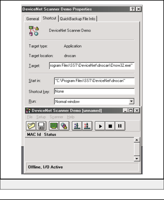
Using DNSW32 or DNSW16
The name of the recommended program is DNSW16.exe or DNSW32.exe
depending upon whether you have installed the 16-bit or 32-bit version. The
typical SST installation placed the program in the following PC path (for ex-
ample):
"C:\Program Files\SST\DeviceNet\dnscan\Dnsw32.exe"
You may execute the program by entering the path given above in Window's
"Run" dialog box.
After installation, you can also find it from Windows 95/98/NT as shown in
the following illustration.
Copyright © 2000 Escort Memory Systems
LRP830-Series Long-Range Passive Reader/Writer 171
Figure 30 — Initial Window of DNSW32
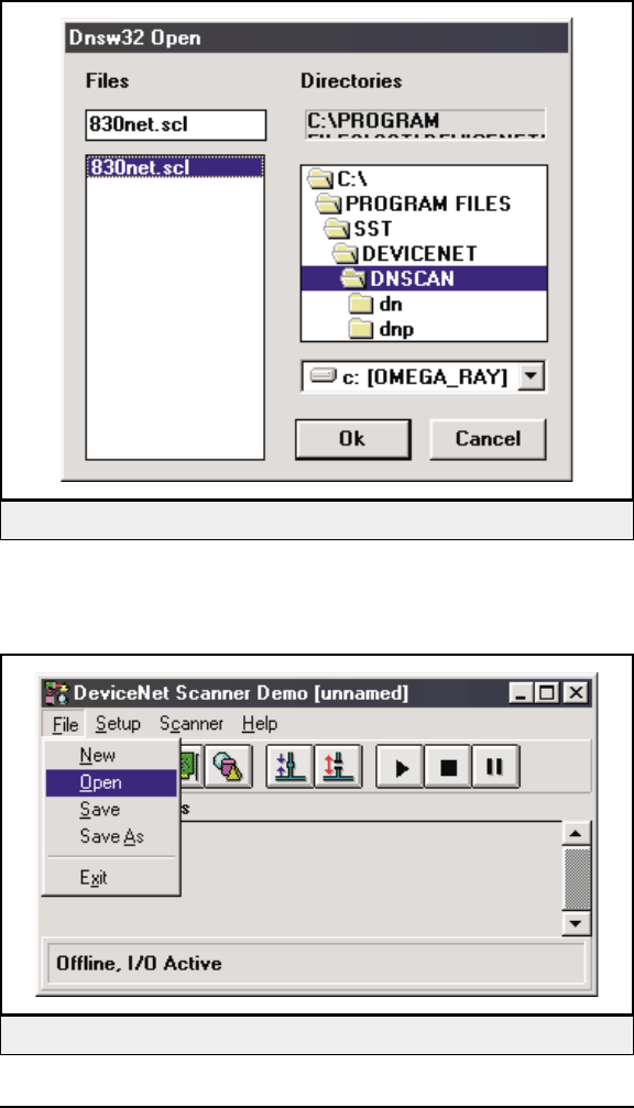
At the Interface Setup window (not shown) just use the defaults by pressing
OK.
Next, load the configuration file ( 830net.SCL), using the FILE>OPEN pull
down menu as depicted in Figure 31 and 32. This file can be found on the
LRP830 installation disk.
Copyright © 2000 Escort Memory Systems
172 LRP830-Series Long-Range Passive Reader/Writer
Figure 31 — Opening the LRP830 Configuration File
Figure 32 — File Open Menu
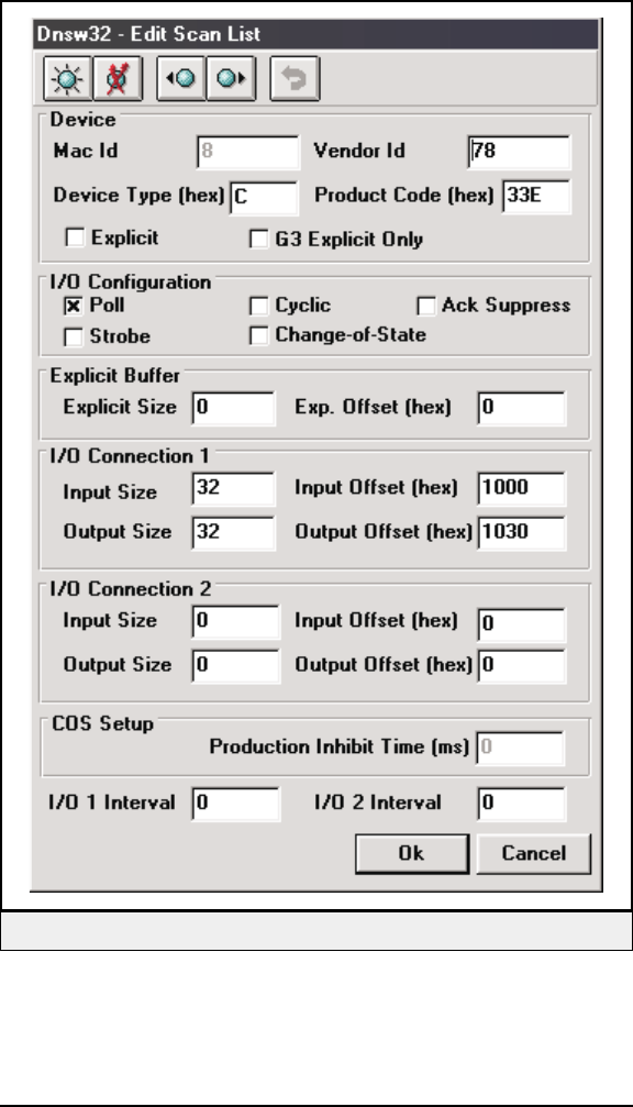
Select Scanner from the Setup menu. Setup the node 8 scan list for the scan-
ner interface as shown in Figure 33.
Note: To insure dynamic update capability in the Device I/O Data window, it
is recommended that you configure the SST scanner and LRP830 for 16
byte messages instead of the 32 shown in the examples.
Copyright © 2000 Escort Memory Systems
LRP830-Series Long-Range Passive Reader/Writer 173
Figure 33 — Node 8 LRP830 Configuration Setup
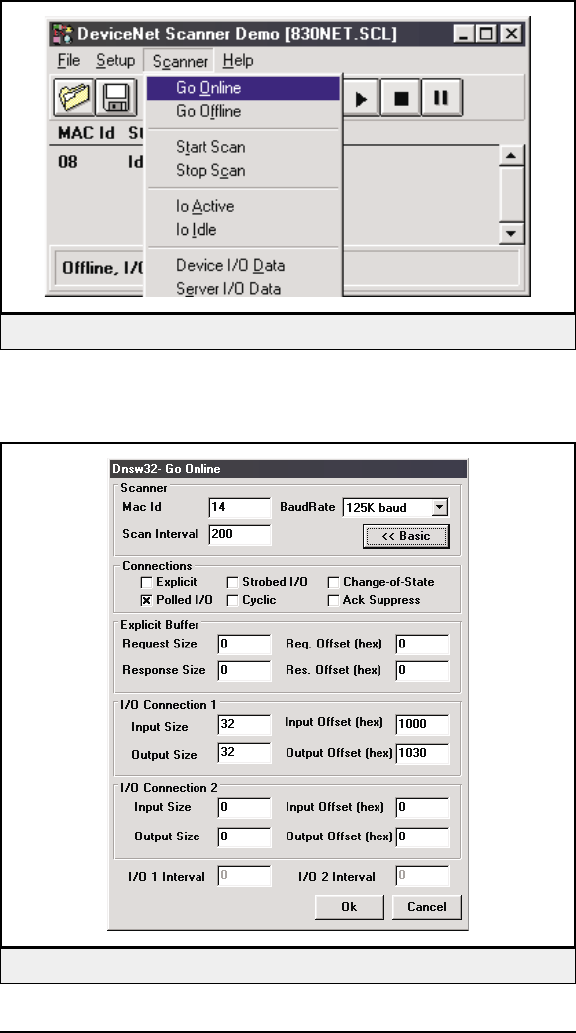
Prepare to go online as depicted in Figure 34.
Select the "Advanced" button from the pop-up window which takes you to
Figure 35.
Copyright © 2000 Escort Memory Systems
174 LRP830-Series Long-Range Passive Reader/Writer
Figure 34 — Going Online
Figure 35 — Advance Setup Dialog Box
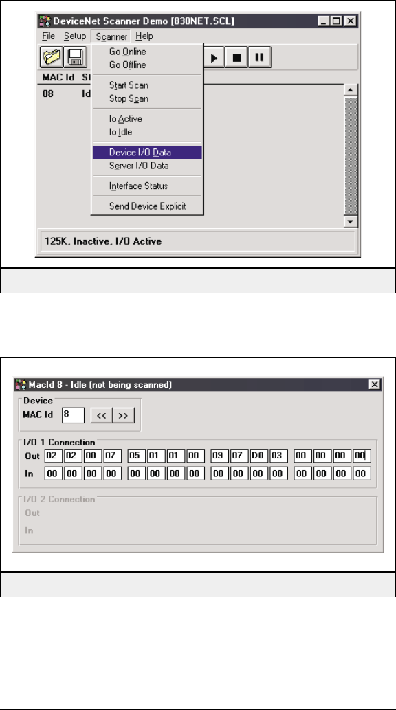
Figure 36 shows how to display the Device I/O data window.
Start scanning now by clicking the PLAY icon, which looks like a black
right triangle on the button bar.
Copyright © 2000 Escort Memory Systems
LRP830-Series Long-Range Passive Reader/Writer 175
Figure 37 — Device I/O Data Window
Figure 36 — Entering the Device I/O Data Window
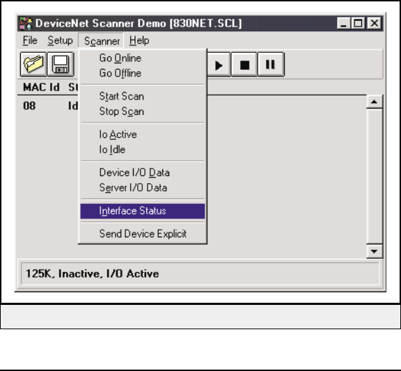
Now you are ready to issue commands from the scanner demo program as
shown in the Figure 32. Message offsets are shown as 00-15 as the demo
only allows 16 characters to be entered. If you need to enter more than 16,
DNSWxx.exe is a MS Visual Basic program (source included by SST)
which you can modify any way you wish.
Figure 37 shows how to enter an ABx Fast block read command (no
checksum) which is output from the scanner to the antenna. The command
format is defined in Section 6.4.
Responses from the antenna dynamically appear in the IN row as shown in
Figure 37.
You may modify the command parameters from the OUT row window. Try
changing the tag read offset and watch the tag read command response data
change as the antenna provides the updated tag data.
The Interface Status Window can be displayed as shown in Figure 38 and
39. This dynamic display is valuable in providing CAN bus status informa-
tion for troubleshooting purposes.
Copyright © 2000 Escort Memory Systems
176 LRP830-Series Long-Range Passive Reader/Writer
Figure 38 — Entering the Interface Status Window
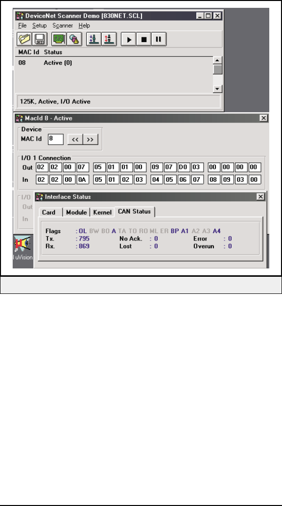
Copyright © 2000 Escort Memory Systems
LRP830-Series Long-Range Passive Reader/Writer 177
Figure 39 — Interface Status/LRP830 Responses
E DEVICENET PROTOCOL EXAMPLES
For the HDR Device Type, when the DeviceNet Scanner Host has data
available to send to the LRP830, it must set the "REQ" bit in the DeviceNet
message header. If the message length is 30 bytes, then the message is frag-
mented and structured as follows from the master scanner. The header byte
is underlined and italicized. DeviceNet Polled protocol is used.
Examples
The following are actual DeviceNet bus message captures by
SS-Technologies DeviceNet Analyzer®software. The first four examples are
based on a 30-byte message length and the last on a 28-byte message length.
Generic: GEN (config display notation)
Command to LRP830: Standard ABx Block Write
This example is from the explanation of ABxS Command 5 found in Section 6.3. It will write 4 bytes of
data to the a starting at address 0064H. A timeout of 2 seconds (07D0H = 2000 x 1 ms) is set for the com-
pletion of the Block Write.
MCID/MSGID Lgth Frg User Data
<63>2:05 [5FD] 08 00 AA 06 00 64 00 04 07
<63>2:05 [5FD] 08 41 D0 00 52 00 46 00 49
<63>2:05 [5FD] 08 42 00 44 FF FF 00 00 00
<63>2:05 [5FD] 08 43 00 00 00 00 00 00 00
<63>2:05 [5FD] 03 84 00 00
Command Response: Standard ABx Block Write
The LRP830 will respond with a command acknowledgment as shown below, or an error message.
MCID/MSGID Lgth Frg User Data
<63>1:15 [3FF] 08 00 AA 06 FF FF 00 00 00
<63>1:15 [3FF] 08 41 00 00 00 00 00 00 00
<63>1:15 [3FF] 08 42 00 00 00 00 00 00 00
<63>1:15 [3FF] 08 43 00 00 00 00 00 00 00
<63>1:15 [3FF] 00 84 00 00
Copyright © 2000 Escort Memory Systems
178 LRP830-Series Long-Range Passive Reader/Writer
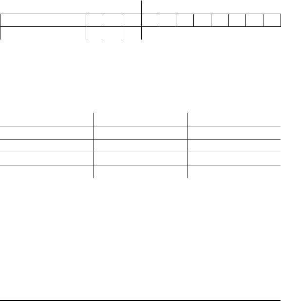
Header Device Type Protocol
When selecting the “Header” device type in the LRP830 configuration, the
following features are available. A special message header is required,
which precedes each ABx command and response.
The Allen Bradley®SLC500 PLC with DeviceNet scanner module
(1747-SDN) must process every message header word coming from the
LRP830. It must also correctly setup a handshake header for every message
going out to the LRP830. An entire word (2 bytes) is required for the header
because some ABx Device Type messages must begin and end on an even
word boundary (e.g. ABx Standard).
Header Format
First word of message from PLC (e.g. in file N10:1) is in the following for-
mat.
Upper Header Byte Lower Header Byte
7654321 0 76543210
NOT USED ACK REQ SEN Reserved
Bit 2 is the acknowledge flag, Bit 1 the request flag, and bit 0 is for a sensor
and is not used by the LRP830.
The possible hex values for the upper header byte are shown below:
Header Word - Binary Header Word - Hex Description
00000001 01 00 Sensor - Not Used
00000010 02 00 REQ - Request
00000100 04 00 ACK - Acknowledge
00000110 06 00 REQ and ACK
Both the REQ and the ACK bits can be set simultaneously when the
LRP830 is both acknowledging a command from the DeviceNet Scanner
Host and indicating it has a response to a previous command.
Note:
When "unmodified" byte ordering is opted, the PLC (for example) reverses
the bytes in each word, so an LRP830 ACK response will appear as 00 06.
Copyright © 2000 Escort Memory Systems
LRP830-Series Long-Range Passive Reader/Writer 179

The length of the header is one word and should appear at the beginning of
each incoming and outgoing message. When you setup your message sizes
you will have 2 bytes overhead. In essence, for a 28 byte message, you will
have 2 bytes of non-data overhead in each DeviceNet message. The
DeviceNet message will be fragmented into four, 8 byte fragments. The first
byte of every fragment is reserved for the fragment header byte. The frag-
ment header byte count is not included in the total message size.
A configuration option called ABx separation, instructs the LRP830 to
place only one ABx command message response in each DeviceNet mes-
sage. The default is set to ABx_sep = on.
Examples
When the PLC has data available to send to the LRP830, it sets the “REQ”
bit in the DeviceNet message header. If the message length is 30 bytes, then
the message is fragmented and structured as follows from the PLC. The
header byte is underlined and italicized.
Note:
The fragmentation byte appears in every fragment, but the header word
appears only in the first fragment. The SENSOR bit (0) may be consistently
on but should be ignored.
Copyright © 2000 Escort Memory Systems
180 LRP830-Series Long-Range Passive Reader/Writer
Header: HDR (config display notation)
Command to LRP830: Standard ABx Block Read
This is from the explanation of ABxS Command 5 found in Section 6.3, pages 39 and 40. It reads 8
bytes of data from the tag starting at address 0101H. A timeout of 2 seconds (07D0H = 2000 x 1 ms) is
set for the completion of the Block Read. The REQ bit is set in the header word as shown in the first row
below.
MCID/MSGID Lgth Frg .Hdr. User Data
<63>2:05 [5FD] 08 00 02 00 AA 05 01 01 00
<63>2:05 [5FD] 08 41 08 07 D0 FF FF 00 00
<63>2:05 [5FD] 08 42 00 00 00 00 00 00 00
<63>2:05 [5FD] 08 43 00 00 00 00 00 00 00
<63>2:05 [5FD] 03 84 00 00
Command Response: Standard ABx Block Read
The LRP830 will send a response containing the bytes read as requested by the above command. In this
example, both the ACK and the REQ bit are set in the header word as shown in the first row below.
MCID/MSGID Lgth Frg .Hdr. User Data
<63>1:15 [3FF] 08 00 06 00 AA 05 00 52 00
<63>1:15 [3FF] 08 41 46 00 49 00 44 00 20
<63>1:15 [3FF] 08 42 00 54 00 61 00 67 FF
<63>1:15 [3FF] 08 43 FF 00 00 00 00 00 00
<63>1:15 [3FF] 03 84 00 00
Poll to LRP830
This is the form of a null command from the PLC to the LRP830. No command is issued with this poll and
only the ACK bit is set in the header word.
MCID/MSGID Lgth Frg .Hdr. User Data
<63>2:05 [5FD] 08 00 04 00 00 00 00 00 00
<63>2:05 [5FD] 08 41 00 00 00 00 00 00 00
<63>2:05 [5FD] 08 42 00 00 00 00 00 00 00
<63>2:05 [5FD] 08 43 00 00 00 00 00 00 00
<63>2:05 [5FD] 03 84 00 00
Copyright © 2000 Escort Memory Systems
LRP830-Series Long-Range Passive Reader/Writer 181
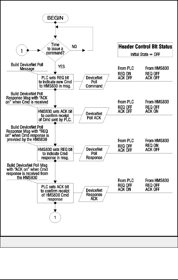
Header Device Type Command Protocol
The following sequence shows the handshaking that will occur between a
PLC DeviceNet scanner host and the LRP830. The ladder logic in the PLC
must respond with an acknowledgment for each message uploaded from the
LRP830.
Copyright © 2000 Escort Memory Systems
182 LRP830-Series Long-Range Passive Reader/Writer
Figure 40 — LRP830 Handshaking Flow

Polls and responses occur at the poll rate of the scanner. The recommended
interscan poll delay setting is 200 milliseconds for initial testing. This set-
ting is made in the DeviceNet Scanner Host. Other polls and responses may
be occurring in between the process blocks shown in Figure 30. This exam-
ple shows only polls and responses that affect the ACK and REQ bits in the
header word. Multiple handshaking bits may be on in a poll or response
message header.
Calculating Message Size
The DeviceNet message will be fragmented into four, 8 byte fragments
when traversing the CAN bus. The first byte of every fragment is reserved
for the fragment header byte. The fragment header byte count is not included
in the total message size.
The LRP830 supports message sizes between 0 and 254 bytes. When speci-
fying the DeviceNet Transmit (Tx) and Receive (Rx) poll message sizes, the
number specified represents the total DeviceNet message size. If the Tx or
Rx message is greater than 8 bytes, the DeviceNet protocol automatically
performs message fragmentation. This means a message is sent as a collec-
tion of 8-byte fragments. The first byte of every fragment is reserved as a
fragment header but is not considered in the message size calculation.
Message fragmentation is typically transparent to the designer, but to maxi-
mize performance and minimize overhead, efficient DeviceNet message
sizes should be considered, as follows.
Generic Device Type
When approximately 29 bytes of user data are required:
29/7=4.14 ~ 5 fragments (always round to next highest whole number).
Thus 35 is the optimal message size in this case (5x7=35).
Copyright © 2000 Escort Memory Systems
LRP830-Series Long-Range Passive Reader/Writer 183

Header Device Type
For Header Device Type the fragment calculation is the same but you must
include the 2 bytes of the header word before you calculate the number of
fragments.
For 29 bytes of I/O message (user) data then:
29 + 2 = 31 (add the two byte header)
31/7=4.43 ~ 5 fragments.
For the above two examples, the user should consider using 35 byte mes-
sages to optimize fragmentation overhead.
35/7=5fragments
When between 29 and 35 bytes are specified for I/O Tx size and I/O Rx size
(in both the DeviceNet Scanner Host and LRP830 DeviceNet configura-
tions), five fragments are generated each time a message is sent or received
over the DeviceNet bus. Each fragment provides space for 7 bytes of user
data and uses 1 byte overhead (which is transparent to the user).
Copyright © 2000 Escort Memory Systems
184 LRP830-Series Long-Range Passive Reader/Writer