BandRich M280 M280 HSUPA Half Mini Card Module User Manual BandRich M280 UMTS Module Ver 03
BandRich Inc. M280 HSUPA Half Mini Card Module BandRich M280 UMTS Module Ver 03
UserManual.wiki
>
BandRich
>
M280 User Manual
BandRich M280 UMTS Module User Manual Ver 03
Navigation menu
Upload a User Manual
Namespaces
Wiki Guide
HTML
PDF
Info
Views
User Manual
Discussion / Help
Navigation

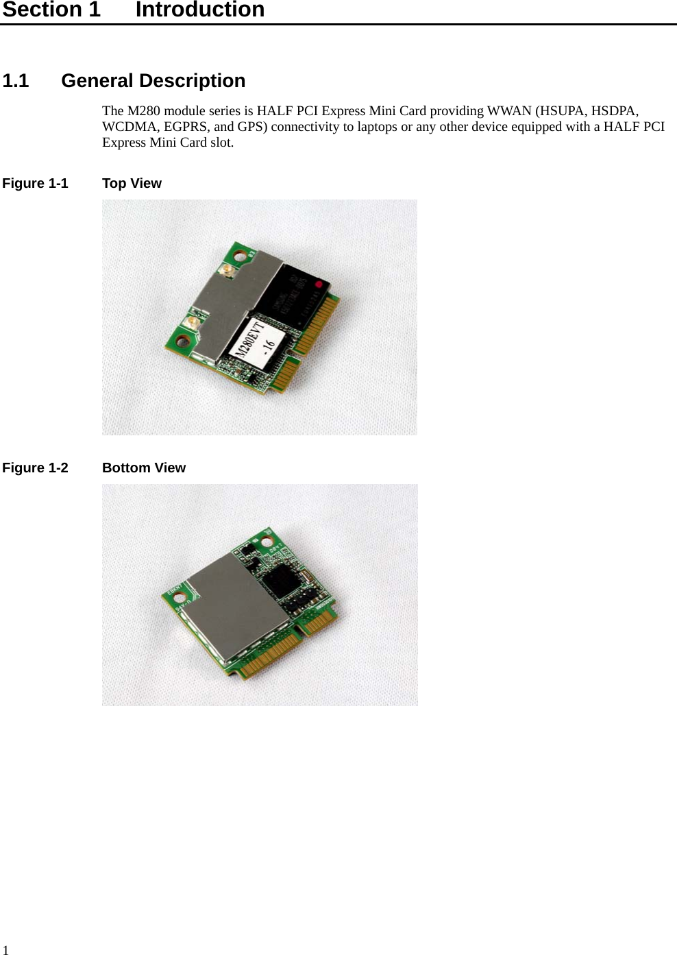
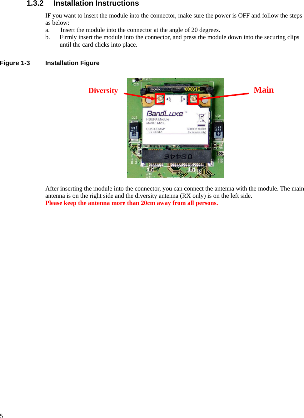
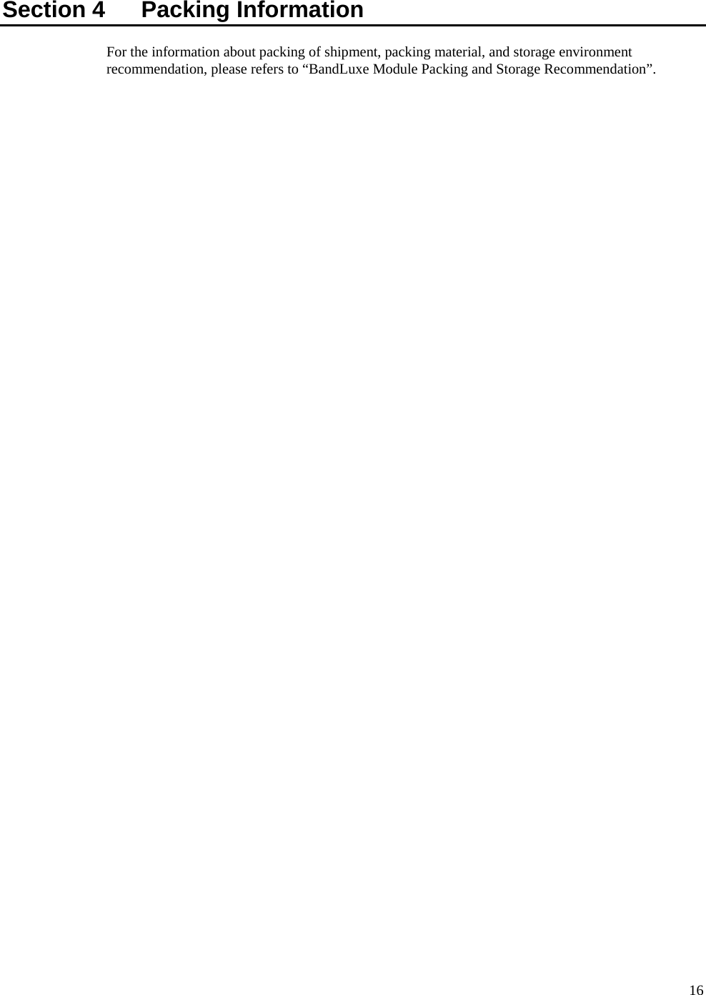
![Section 3 AT Command Set Reference For the description of BandLuxe AT Command API, please refer to Table 3-1 for reference. Table 3-1 Abbreviations and Acronyms Table BandLuxe HSPA Modem AT Command Interface API Serial Port Name: BandLuxe AT CMD Interface AT Command Command description Command Format AT&F Set all current parameters to manufacturer defaults AT&F[<mode>] AT&V Display current configuration AT&V[<mode>] ATE Enable command echo ATE ATI Display product identification information ATI ATQ Set result code presentation mode ATQ[<value>] ATV Set result code format mode ATV[<value>] ATZ Set all current parameters to user defined profile ATZ[<mode>] ATS3 Write command line termination character S3=<n> S3? S3=? ATS4 Set response formatting character S4=<n> S4? S4=? ATS5 Write command line editing character S5=<n> S5? S5=? AT+GMI Request manufacturer identification AT+GMI AT+GMM Request model identification AT+GMM AT+GMR Request revision identification of software status AT+GMR AT+GSN Request serial number identification AT+GSN AT+GCAP Request complete TA capabilities list AT+GCAP AT+GCAP? AT+CBST Select bearer service type AT+CBST=[<speed>[, <name>[, <ce>]]] AT+CBST? AT+CBST=? AT+CRLP Select radio link protocol param AT+CRLP=[<iws>[, <mws>[, <T1>[, <N2>]]]] AT+CRLP? AT+CRLP=? AT+CREG Network registration AT+CREG=[<n>] AT+CREG? AT+CREG=? AT+CGREG GPRS network registration status AT+CGREG=[<n>] AT+CGREG? AT+CGREG=?](https://usermanual.wiki/BandRich/M280/User-Guide-1075777-Page-14.png)
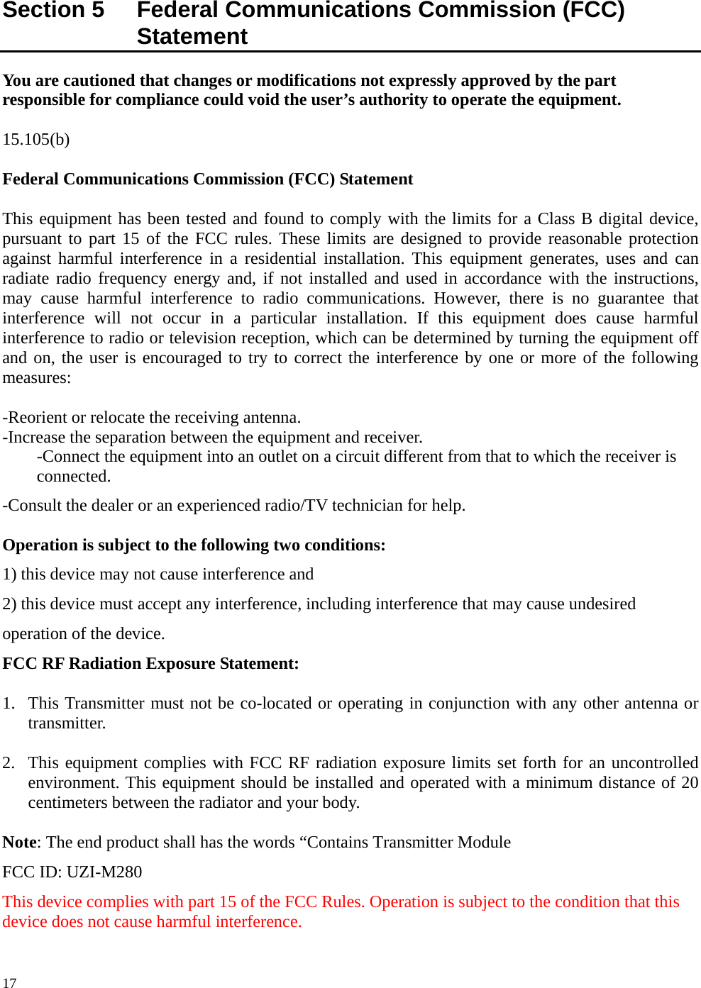
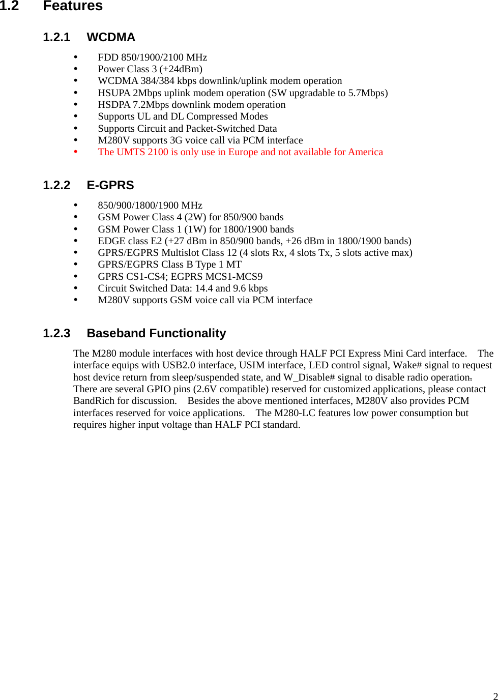
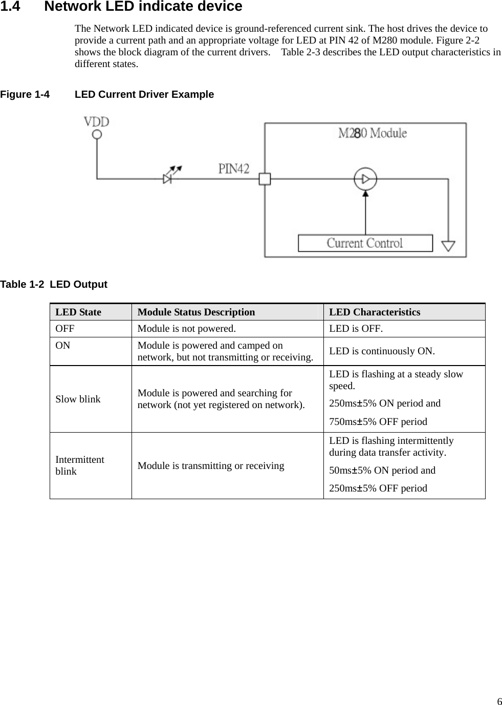
![12 AT Command Command description Command Format AT+CFUN Full functionality mode AT+CFUN=<mode>[,<rst>] AT+CFUN? AT+CFUN=? AT+GCAP Request complete TA capabilities list AT+GCAP AT+GCAP=? AT+CSCS Used Character Set AT+CSCS=[<chset>] AT+CSCS? AT+CSCS=? AT+CEER Cause Location ID for the extended error report AT+CEER AT+CMEE Report Mobile Terminal Error AT+CMEE=[<n>] AT+CMEE? AT+CMEE=? AT+CGDCONT Define PDP Context AT+CGDCONT=[<cid> [,<PDP_type> [,<APN> [,<PDP_addr> [,<d_comp> ,<h_comp>]]]]]] AT+CGDCONT? AT+CGDCONT=? AT+CGDSCONT Define Secondary PDP Context AT+CGDSCONT=[<cid>,<p_cid>[,<d_comp>[,<h_comp>]]] AT+CGDSCONT? AT+CGDSCONT=? AT+CGTFT Traffic Flow Template AT+CGTFT=[<cid>, [<packet filter identifier>, <evaluation precedence index> [,<source address and subnet mask> [,<protocol number (ipv4) / next header (ipv6)> [,<destination port range> [,<source port range> [,<ipsec security parameter index (spi)> [,<type of service (tos) (ipv4) and mask / traffic class (ipv6) and mask> [,<flow label (ipv6)> ]]]]]]]]] AT+CGTFT? AT+CGTFT=? AT+CGEQREQ 3G Quality of Service Profile (Requested) AT+CGEQREQ=[<cid> [,<Traffic class> [,<Maximum bitrate UL> [,<Maximum bitrate DL> [,<Guaranteed bitrate UL> [,<Guaranteed bitrate DL> [,<Delivery order> [,<Maximum SDU size> [,<SDU error ratio> [,<Residual bit error ratio> [,<Delivery of erroneous SDUs> [,<Transfer delay> [,<Traffic handling priority> [,<Source statistics descriptor> [,<Signalling indication>]]]]]]]]]]]]]]] AT+CGEQREQ? AT+CGEQREQ=?](https://usermanual.wiki/BandRich/M280/User-Guide-1075777-Page-15.png)
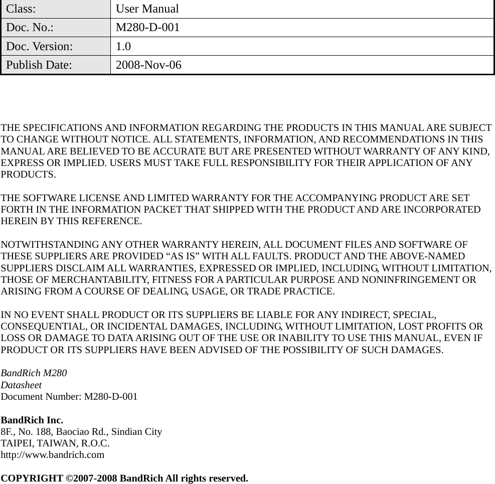
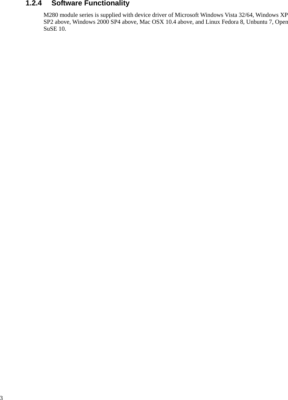
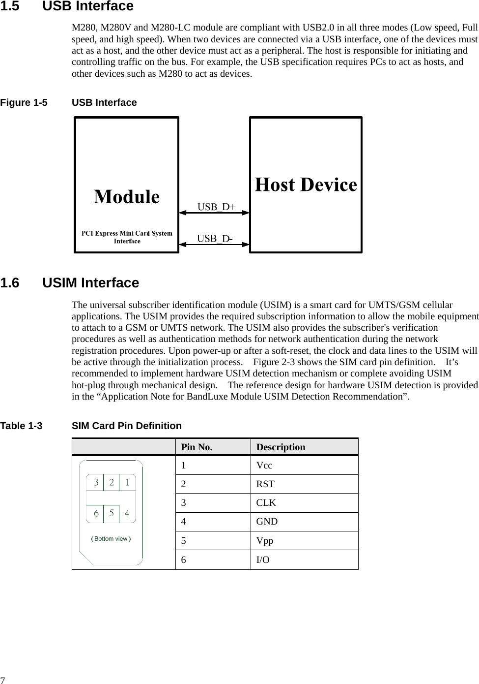
![13 AT Command Command description Command Format AT+CGEQMIN 3G Quality of Service Profile (Minimum acceptable) AT+CGEQMIN=[<cid> [,<Traffic class> [,<Maximum bitrate UL> [,<Maximum bitrate DL> [,<Guaranteed bitrate UL> [,<Guaranteed bitrate DL> [,<Delivery order> [,<Maximum SDU size> [,<SDU error ratio> [,<Residual bit error ratio> [,<Delivery of erroneous SDUs> [,<Transfer delay> [,<Traffic handling priority> [,<Source statistics descriptor> [,<Signalling indication>]]]]]]]]]]]]]]] AT+CGEQMIN? AT+CGEQMIN=? AT+CGQREQ Quality of Service Profile (Requested) AT+CGQREQ=[<cid>[,<precedence>[,<delay>[,<reliability.> [,<peak>[,<mean>]]]]]] AT+CGQREQ? AT+CGQREQ=? AT+CGQMIN Quality of Service Profile (Minimum acceptable) AT+CGQMIN=[<cid>[,<precedence>[,<delay>[,<reliability.> [,<peak>[,<mean>]]]]]] AT+CGQMIN? AT+CGQMIN=? AT+CGEREP Subscriber number AT+CGEREP=[<mode>[,<bfr>]] AT+CGEREP? AT+CGEREP=? AT+CGPADDR Show PDP address AT+CGPADDR=[<cid> [,<cid> [,…]]] AT+CGPADDR=? AT+CGCLASS GPRS mobile station class AT+CGCLASS= [<class>] AT+CGCLASS? AT+CGCLASS=? AT+CGSMS Select service for MO SMS messages AT+CGSMS=[<service>] AT+CGSMS? AT+CGSMS=? AT+CSMS Select Message Service AT+CSMS=<service> AT+CSMS? AT+CSMS=? AT+CMGF Select SMS message format AT+CMGF=[<mode>] AT+CMGF? AT+CMGF=? AT+CSCA Service Centrer Address AT+CSCA=<sca>[,<tosca>] AT+CSCA? AT+CSCA=? AT+CSMP Set SMS text mode parameters AT+CSDH Show SMS text mode parameters AT+CSDH=[<show>] AT+CSDH? AT+CSDH=?](https://usermanual.wiki/BandRich/M280/User-Guide-1075777-Page-16.png)
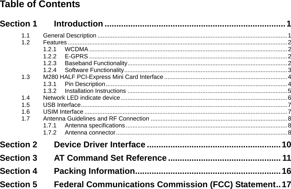
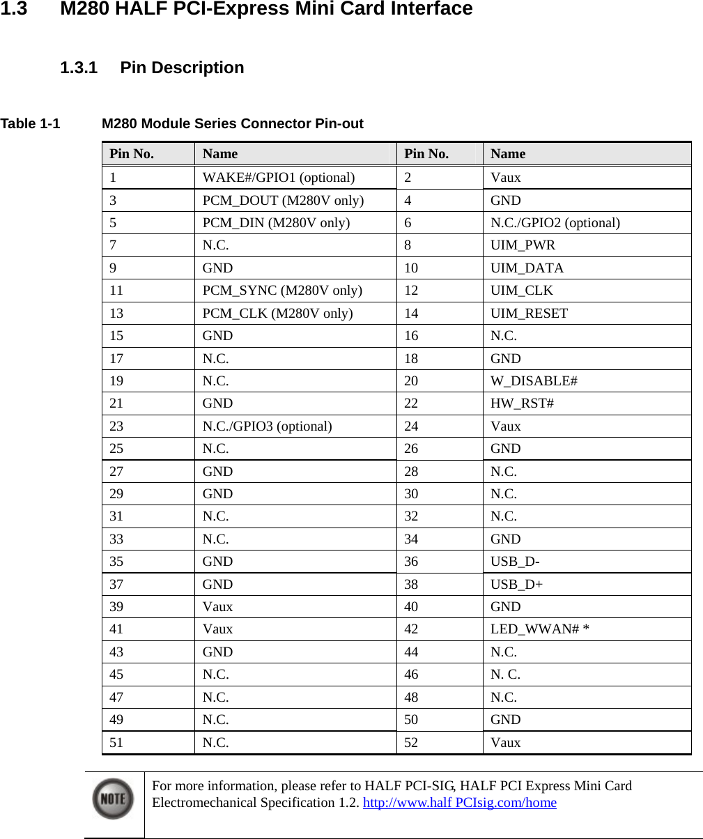
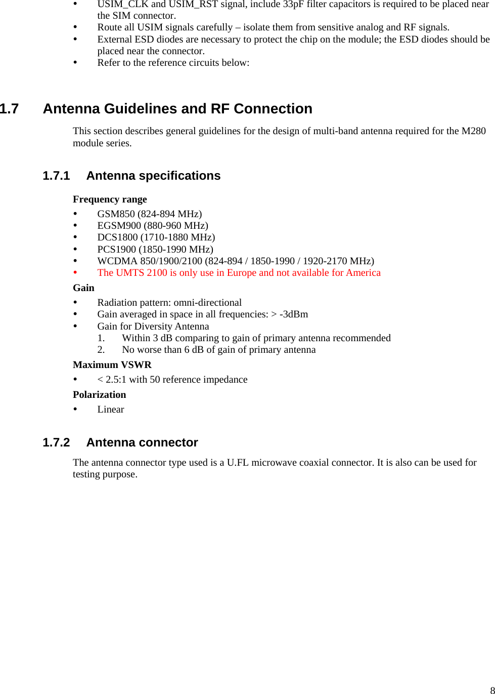
![14 AT Command Command description Command Format AT+CSQ Request signal strength AT+CSQ AT+CSQ=? AT+CPIN Check PIN Status AT+CPIN=<pin>[,<newpin>] AT+CPIN? AT+CPIN=? AT+CGATT PS attach / detach AT+CGATT= [<state>] AT+CGATT? AT+CGATT=? AT+CGACT PDP context activate or deactivate AT+CGACT=[<state> [,<cid>[,<cid>[,…]]]] AT+CGACT? AT+CGACT=? AT+CGCMOD PDP Context Modify AT+CGCMOD=[<cid>[,<cid>[,…]]] AT+CGCMOD=? AT+CPBS Select phone book memory storage AT+CPBS=<storage> AT+CPBS? AT+CPBS=? AT+CPBR Read Phonebook Memory entries AT+CPBR=<index1>[,<index2>] AT+CPBR? AT+CPBF Find Phonebook Memory entries AT+CPBF=<findtext> AT+CPBF=? AT+CPBW Write phone book entry AT+CPBW=[<index>][,<number>[,<type>[,<text>]]] AT+CPBW=? AT+CPMS Preferred Message Storage AT+CPMS=<mem1>[, <mem2>[,<mem3>]] AT+CPMS? AT+CPMS=? AT+CNMI New Message Indications to TE AT+CNMI=[<mode>[,<mt>[,<bm>[,<ds>[,<bfr>]]]]] AT+CNMI? AT+CNMI=? AT+CMGL List Messages AT+CMGL[=<stat>] AT+CMGL=? AT+CMGR Read Message AT+CMGR=<index> AT+CMGR=? AT+CMGS Send SMS message AT+CMGS=<da>[,<toda>] AT+CMGS=? AT+CMGD Delete SMS message AT+CMGD=<index> AT+CMGD=? AT+CNMA New SMS message acknowledge to ME/TE AT+CNMA AT+CNMA=? AT+COPS Operator selection AT+COPS[=<mode>[, <format>[, <oper>]]] AT+COPS? AT+COPS=? AT+CLCK Facility lock AT+CLCK=<fac>,<mode>[,<passwd>[,<class>]] AT+CLCK=?](https://usermanual.wiki/BandRich/M280/User-Guide-1075777-Page-17.png)
![15 AT Command Command description Command Format AT+CPWD Change password AT+CPWD=<fac>,<oldpwd>,<newpwd> AT+CPWD=? AT+CUSD Unstructured supplementary service data AT+CUSD=[<n>[,<str>[,<dcs>]]] AT+CUSD? AT+CUSD=? AT+CIMI Read IMSI AT+CIMI AT+CIMI=? AT+CGMI Request manufacturer identification AT+CGMI AT+CGMM Request model identification AT+CGMM AT+CGMR Request revision identification AT+CGMR AT+CGSN Request product serial number identification AT+CGSN AT+CNUM Subscriber number AT+CNUM AT+CNUM=? AT+CSIM Generic SIM access +COLP=[<n>] AT+CRSM Restricted SIM access AT+CRSM=<command>[,<fileid>[,<P1>,<P2>,<P3>[,<data>]]] AT+CRSM=? AT+COPN Read operator names AT+COPN AT+COPN=? AT+CPOL Preferred PLMN list AT+CPOL=[<index>][,<format>[,<oper>]] AT+CPOL? AT+CPOL=? AT+CPLS Selection of preferred PLMN list AT+CPLS=<list> AT+CPLS? AT+CPLS=? AT+CTZR Time Zone Reporting AT+CTZR=<onoff> AT+CTZR? AT+CTZR=? AT+CPINC The retries count of PIN1, PIN2, PUK1 or PUK2 AT+CPINC AT+CPINC=?](https://usermanual.wiki/BandRich/M280/User-Guide-1075777-Page-18.png)